1
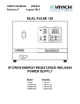
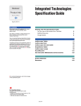
MAS-3B
Non-invasive Tube Current Probe Adapter
User's Manual - English - Version 2.0A
RTI Electronics AB reserves all rights to make changes in the MAS-3B and the
information in this document without prior notice.
RTI Electronics AB assumes no responsibility for any errors or consequential damages
that may result from the use or misinterpretation of any information contained in this
document.
Copyright © 1993-2010 by RTI Electronics AB. All rights reserved.
Content of this document may not be reproduced for any other purpose than supporting
the use of the product without prior permission from RTI Electronics AB.
Contact Information World-Wide
Contact Information United States
RTI Electronics AB
Flöjelbergsgatan 8 C
SE-431 37 MÖLNDAL
Sweden
RTI Electronics Inc.
1275 Bloomfield Ave., Building 5,
Unit 29A, Fairfield, NJ 07004
USA
Phone: Int. +46 31 7463600
Phone: 800-222-7537 (Toll free)
Int. +1-973-335-4200
Fax: Int. 1-973-335-1225
Fax:
Int. +46 31 270573
E-mail
Sales: [email protected]
Support: [email protected]
Service: [email protected]
E-mail
Sales: [email protected]
Support: [email protected]
Service: [email protected]
Web site: http://www.rti.se
Web site: http://www.rti.se
RTI article number: 9630510-00
2
Contents
Intended Use of the MAS-3B
Together with instruments from RTI Electronics AB it is to be used for independent
service and quality control, as well as measurements of kerma, kerma rate, kVp,
tube current, exposure time, luminance, and illuminance within limitations stated
below.
If installed according to accompanying documents, the product is intended to be
used together with all diagnostic X-ray equipment except for:
- therapeutical X-ray sources.
- X-ray equipment with tube potential below 20 kV.
- X-ray equipment on which the instrument cannot be mounted properly, e.g.
equipment where the beam field size is narrower than the active part of the detector.
- specific types of X-ray equipment listed in the instructions for use or in additional
information from the manufacturer.
With the X-ray installation in stand-by conditions without patients present, the
product is intended to be used:
- to provide the operator with information on radiation beam parameters that might
influence further steps in an examination but not an ongoing exposure.
- for assessing the performance of the X-ray equipment.
- for evaluation of examination techniques and procedures.
- for service and maintenance measurements.
- for quality control measurements.
- for educational purposes, authority supervision etc.
The product is intended to be used by hospital physicists, X-ray engineers,
manufacturer's service teams, and other professionals with similar tasks and
competencies. The operator needs a short training to be able to use the product as
intended. This training can be achieved either by careful study of the manual,
studies of the built-in help function in measurement software or, on request, in a
course provided by the manufacturer.
The product is intended to be used inside X-ray rooms ready for clinical use and can
safely be left switched on and in any measuring mode in the vicinity of patients.
The product is NOT intended to be used:
- for direct control of diagnostic X-ray equipment performance during irradiation of a
patient.
- so that patients or other unqualified persons can change settings of operating
parameters during and immediately before and after measurements.
MAS-3B User's Manual
2010-10/2.0A
Contents
3
Table of Contents
1.
INTRODUCTION
............................................................................................................. 4
1.1
2.
A Presentation
.....................................................................................................
of the MAS-3B
4
FUNCTION
.............................................................................................................
AND CONNECTION
7
2.1
2.2
3.
Connection.....................................................................................................
of the MAS-3B
7
Battery and
.....................................................................................................
Charging
12
MEASUREMENTS
............................................................................................................. 13
3.1
3.2
4.
Measurements
.....................................................................................................
of the mAs and mA Value
13
Hints and .....................................................................................................
Trouble-shooting
14
SAFETY
.............................................................................................................
PRECAUTIONS
15
4.1
5.
General Rules
..................................................................................................... 15
SPECIFICATIONS
............................................................................................................. 16
5.1
General Specifications
.....................................................................................................
for MAS-3B
16
Index
............................................................................................................. 17
Note!
For a full description of the Piranha or Barracuda, see the Piranha or
Barracuda Reference Manual.
That Manual can be found on the Product CD or be downloaded from RTI's
website (www.rti.se). The manual is available both as PDF and Browser
format. The Browser (HTML) format is recommended for easy searching.
2010-10/2.0A
MAS-3B User's Manual
4
1
1.1
1. INTRODUCTION
A Presentation of the MAS-3B
INTRODUCTION
A Presentation of the MAS-3B
The MAS-3B is a non invasive mA and mAs probe system for use together with the
Piranha or Barracuda. The system provides a way to measure the tube mA and mAs
on any X-ray equipment.
The MAS-3B have a very sensitive current probe based on the IPCT (Integrated
Parametric Current Transformer) method that is 100 times more precise than Hall
effect device
The MAS-3B probe system can measure from 0,1 mA to 2000 mA. The mA waveform
can also be collected and displayed using the software for Piranha or Barracuda.
This new updated model is self contained and only use an interface cable to the
Piranha or Barracuda. The measuring hole is 82 mm so it accepts all major mammo
and radiography HV cables.
Passing the high voltage (HV) cable through the probe aperture connects the current
probe.
The MAS-3B measure the electromagnetic field created by the cable when passing the
measuring hole. Accurate readings can be done independent of the high voltage cable
position. An isolation ring is provided when extremely low mA should be measured to
avoid that ground currents in the HV cable shield could interfere with the true tube
current value.
MAS-3B can both run continuous on USB power or on battery using built in
rechargeable batteries.
The MAS-3B has built-in second order DC – 500 Hz low-pass filter.
Normally the system is used with the kV probe for Piranha or Barracuda to use this
detector to "gate" the mA and mAs value together with kV, time, dose, dose rate and
beam filtration and its waveform in one exposure.
This system is also preferable when adding an absolute mAs reference value for your
mAs linearity test. You can easily (by using the software for Piranha or Barracuda tran
sform your relative output measurement values to absolute mAs values even for small
mAs measurements.
A benefit with this method is that you avoid large measurement errors for small mAs
values. This is often the case with ordinary mAs meters that is not sensitive to the
current waveform. Using the software, a certain portion of the mA waveform can be
selected using the radiation waveform as reference.
MAS-3B User's Manual
2010-10/2.0A
1. INTRODUCTION
A Presentation of the MAS-3B
5
Connection of MAS-3B to a RAD tube
Rad 70 kV 300 mA 100 ms Piranha and MAS-3B
2010-10/2.0A
MAS-3B User's Manual
6
1. INTRODUCTION
A Presentation of the MAS-3B
Pulsed fluoro 80 kV 1 mA 12.5 frames per sec. Piranha and MAS-3B
Connection of MAS-3B to a
mammo tube
MAS-3B connected to a mammo tube triggered
directly on the mA signal .
CAUTION:
Users of mAs meters must be aware of the potential damage to
generators and electrical human hazards in the case of improper
connection or failure of any part of the meter circuit. The MAS-3 is
intended for use only by those skilled in the calibration and repair of
X-ray machines. Please read the section SAFETY PRECAUTIONS 15
for more safety rules.
MAS-3B User's Manual
2010-10/2.0A
1. INTRODUCTION
A Presentation of the MAS-3B
2
2.1
7
FUNCTION AND CONNECTION
Connection of the MAS-3B
Please be aware that high voltage may exist if the mA probe connection is not properly
made. Read the SAFETY PRECAUTIONS 15 chapter before you start measuring!
· Power down the X-ray unit and turn OFF the MAS-3B.
Caution!
Users of mAs meters must be aware of the potential damage to generators
and electrical human hazards in the case of improper connection or failure
of any part of the meter circuit. The MAS-3B is intended for use only by
those skilled in the calibration and repair of X-ray machines. Please read
SAFETY PRECAUTIONS 15 for more safety rules.
· Locate the HV + cable, Disconnect the anode cable connector, see figure 2.1 and
2.4
Figure 2-1
Locate the anode cable and its connection to the tube
2010-10/2.0A
MAS-3B User's Manual
8
2. FUNCTION AND CONNECTION
Connection of the MAS-3B
· Disconnect the HV cable. Put the MAS-3B probe over the cable connector. Please
observe the right polarity. It is indicated by the arrow on the probe (from + to -).
If you do not find the polarity information, do not be worried, the MAS-3B has a polarity
switch on the front panel. See figure 2.6.
Figure 2.2 Anode cable disconnection and connection of MAS-3B Note the polarity of the
probe. The arrow on the probe is pointing at the tube anode side.
MAS-3B User's Manual
2010-10/2.0A
2. FUNCTION AND CONNECTION
Connection of the MAS-3B
9
· Mount the blue insulation ring. The ring insulates the lock nut from the strain relief
guard. This is to avoid ground currents. See figure 2.3.
Figure 2.3
Insulation ring should be placed between the lock nut and the strain relief guard.
· Tighten the lock nut firmly.
2010-10/2.0A
MAS-3B User's Manual
10
2. FUNCTION AND CONNECTION
Connection of the MAS-3B
· Connect the MAS-3B to the Piranha or Barracuda.
See figure 2.4 and 2.5 for a complete setup of the MAS-3B system.
Figure 2.4
MAS-3 setup with Piranha as a trigger
Figure 2.5
MAS-3 setup with MPD as a trigger
Figure 2.4 shows a complete setup of the MAS-3 system together with the Piranha or
Barracuda.
NOTE! Make all connections without power on the instruments.
Place the MAS-3B probe at least 20 cm away from the tube to avoid disturbance from
the tube rotation.
· Now connect the MAS-3B to the detector input of the Piranha or Barracuda using the
included cable. Attach the round Lemo female connector to the connector that is
marked Lemo OUT on the probe, and the other end to the electrometer input on your
meter.
MAS-3B User's Manual
2010-10/2.0A
2. FUNCTION AND CONNECTION
Connection of the MAS-3B
11
· Turn ON the MAS-3B turning the round rotary switch to the "Battery ON" position.
Figure 2.6
Setup of front panel of MAS-3
· Check that the polarity switch is set to in "Normal" ,Select "Battery On" with the red
rotary switch. The green LED will now indicate that the MAS-3B is powered ON. The
Probe is now ready to use.
If the red “LoBat” LED lights up, it indicates that the battery voltage is low. Please
recharge the MAS-3B before measuring. Alternatively you can turn the rotary switch to
"Power USB On" position and connect the USB cable to your 5 Volt power supply. See
Battery and charging 12 .
Please note that to be able to "gate" the measurement for simultaneously
measurement of not only mA and mAs you also should place the kV detector for the
Piranha or Barracuda in the X-ray field as indicated in figure 2.4 and 2.5
2010-10/2.0A
MAS-3B User's Manual
12
2.2
2. FUNCTION AND CONNECTION
Battery and Charging
Battery and Charging
The MAS-3B uses a built in rechargeable battery which you charge using the standard
mini-USB connector at the front panel of the probe. You can use either:
· a USB cable and charge it from your computer
· the charger that came with your Piranha,
· or a standard USB charger with an output of +5 V/1 A output.
Finally you need to turn the rotary switch to position "Charge USB /Off".
Figure 2.7
· When the yellow LED is lit it indicates that the battery is charging. When the yellow
LED switches off the MAS-3B battery is fully charged. It can take more than 6 hours
but normally a fully charged battery can run the MAS-3B for more than 3 hours on
battery before the "Lo Batt" Led is lit and you have to charge the battery again .
The battery cannot be over-charged, since the MAS-3B contains a charging
controller.
Note that you cannot use the MAS-3B while it is charging.
You do have an alternative if you use the probe in a standard setup all the time, you
can then use the MAS-3B continuously when selecting "USB Power On".
If the red "Low Power" LED light up then you charger cannot provides enough current .
The Piranha charger provides enough current output for this mode. Also any standard
USB charger that provides at least 5V/1A could also be used but the power output from
a PC USB port cannot since this port typically limits the current to 500 mA.
MAS-3B User's Manual
2010-10/2.0A
2. FUNCTION AND CONNECTION
Battery and Charging
3
3.1
13
MEASUREMENTS
Measurements of the mAs and mA Value
Setup the MAS-3B according to the section Connection of the MAS-3B
the MAS-3B and then the Piranha or Barracuda.
7
. Power on
Start the Ocean, oRTIgo or QABrowser, as described in the software manual and then
select the appropriate Real-time Meter display part of the software.
The example 1 here is for the QABrowser :
Start the QABrowser, tap Measure, Radiography, Tube Current, (for the Barracuda
you must also choose the EMM module) to be able to read the current. It is typically
shown in the unit "mA".
Tap Reset, then "0" should be displayed.
The offset adjustment procedure for Piranha or Barracuda is finished and the MAS-3B
is ready for measurements.
Now just perform an exposure and the QABrowser will show you readings of tube
current (mA) and tube charge (mAs). You may also study the tube current waveform by
tapping the Wave button. The Piranha or Barracuda starts to measure when the mA
signal is greater than approximately 0.1 mA when using the MAS-3B. For long
exposure times, you may want to switch to the Continuous update mode. The
QABrowser will then update the display continuously during the exposure. (See
Settings in the Piranha or Barracuda manual).
For more detail information of measurement, please study the documentation for the
software.
Don't forget to turn the rotary switch to "Charge USB/OFF" position to turn off the
MAS-3.
Note that when using a PC connected to mains and at the same time a
cable to the Piranha or Barracuda, ground loops may arise that generates
ground currents that affects the measurements. It is recommended to
either connect wirelessly between the PC and meter, or run a laptop PC
on battery.
2010-10/2.0A
MAS-3B User's Manual
14
3.2
3. MEASUREMENTS
Measurements of the mAs and mA Value
Hints and Trouble-shooting
·
If no current can be measured, please check the direction of current, Piranha or
Barracuda CANNOT measure negative current. The arrow on the probe should
point at the tube anode. You can use the Polarity switch on the front panel to
change the polarity . This make it very handy since you do not have to physically
take apart the HV circuitry to "rotate" the probe to change polarity if it set up wrong
in the first place.
·
Please use "All" and put the Piranha or Barracuda in the X-ray field to “gate” the
measurements if it is a problem to hold the mAs value when using the single tube
current mode. This may happen because of current noise from the rotating anode
engine. You may also use the "Meter Adjust" part of the software. For Ocean all
meter settings are found on the tabs to the right. Change the threshold setting to
"High" to increase the trig level to avoid false triggering.
·
The use of the blue isolating ring mentionned before is mandatory if current less
than appr 20 mA should be measured without influence of ground current noise
This ring insulates the cable shield from the tube housing so that the high voltage
cable only is connected to protective earth at one end, i.e. at the generator. If both
ends of the cable are connected to protective earth, there will be a fluctuating
ground current floating in the shield, that will affect the measurements and give
unstable readings.
·
The position of the probe in relation to other current noise sources is important to
consider. Specially please do not put the probe closer than app 20 cm from the
tube since the electromagnetic field from the rotator in the tube can be picked up by
the probe specially when the tube starts to rotate just before measurement .
Hint use the kV detector to" gate " the tube current measurement using the X-ray
signal as a trigger since this signal is much more noise free .
·
Please note that the filament current does not normally affect the probe reading
since its net current is zero in the HV cable. Therefore also tube current
measurement with the negative HV cable is possible even if this cable also
supports the filament current itself
·
A 8 meters extension cable EXT-1 is available, to further extend the cable.
·
A good rule is that the mA waveform should be studied whenever checking the mA
station.
Large inaccuracy can arise when small values are measured if the mA waveform
information is not available.
If the value is lower than 10 mAs, special attention must be drawn to how the
charge supplied to the capacitance in the high voltage cable will influence the
measuring result. See picture below.
The easiest way to do this is to use the oRTIgo/Ocean waveform analyzer.
·
Note that when using a PC connected to mains and at the same time a cable to the
Piranha or Barracuda, ground loops may arise that generates ground currents that
affect the measurements. It is recommended to connect wirelessly between the PC
and meter, or run a laptop PC on battery.
MAS-3B User's Manual
2010-10/2.0A
4. SAFETY PRECAUTIONS
4
4.1
15
SAFETY PRECAUTIONS
General Rules
•
Only use the MAS-3B system if you are authorised to work with calibration
and service of X-ray equipment.
•
Always switch off the X-ray generator and wait appr. one minute before you
make any connection or disconnection of the high voltage cables.
•
Do NOT expose the instruments to direct sunlight, extremes of temperature
and humidity, or dew fall.
•
Do not exceed maximum current for the MAS-3B system (2000 mA).
•
Do NOT forget to turn the MAS-3B adapter box off after use.
Note!
The MAS-3B is intended for service and quality control of diagnostic
X-ray equipment. It is not intended for use during or together with
diagnostic examinations of patients.
RTI Electronics AB takes no responsibility for misuse of the MAS-3B or use together
with products that the MAS-3B is not intended for.
RTI Electronics AB assumes no responsibility for customers not following these safety
precautions.
2010-10/2.0A
MAS-3B User's Manual
16
5
5.1
4. SAFETY PRECAUTIONS
General Rules
SPECIFICATIONS
General Specifications for MAS-3B
Specifications are valid after a warm-up time of one minute and presuming reference
conditions.
Reference conditions
Temperature
Relative humidity
Specifications
Current range
+18 °C to +23 °C
50 %
0.1 - 2000 mA
Charge range
0.01 - (at least) 9999 mAs
Inaccuracy
±1 % or ±0.02 mA
Frequency range, bandwidth
DC - 500 Hz (-3 dB)
Random error
1%
Maximum dimensions of high voltage
(HV) cable
82 mm
Voltage insulation
5 kV current conductor to ground
Scale/calibration factor
1.0 nA/0.25 mA
Battery operation time after full charge
> 3 hours.
Operating temperature
and relative humidity:
15 - 30 °C
at <80 % relative humidity
Storage temperature
-10 °C to +50 °C
Battery type
Li-Ion, 2x 2100 mAh
Weight (without charger)
600g
Dimensions
200x112x51 mm
MAS-3B User's Manual
2010-10/2.0A
Index
-R-
Index
Note!
Page references in this Index points to the
first page of the section it is mentioned, not
the exact page.
-AAccuracy
17
Range 16
Rechargeable
Red LED 7
12
-SSafety 15
Specifications 16
Storage temperature
16
-T-
16
Trouble-shooting
-B-
14
-U-
Bandwidth 16
Battery 12, 16
Battery life 16
Battery type 16
USB charger
12
-W-
-CCalibration factor 16
Capacitance in the HV cable 14
Charging 12
Connection of the MAS-3B 7
Weight 16
Work flow 13
-YYellow LED
7, 12
-DDimensions
16
-EExtension cable
14
-FFrequency range
16
-GGeneral Rules 15
Green LED 7
Ground loops 14
-HHints and Trouble-shooting
HV cable capacitance 14
14
-IInaccuracy 16
Introduction 4
-MMeasurements 13
Measuring Range 16
-NNegative current
Noise 14
14
-OOperating temperature
Output 7
16
-PPiranha power supply
Polarity 7
Power ON 7
2010-10/2.0A
12
MAS-3B User's Manual
18
Notice
Notes
MAS-3B User's Manual
2010-10/2.0A