1
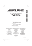
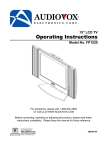
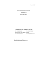
M401 Installation Manual
Copyright © 2013 Conqueror Design and Engineering Ltd.
M401 Installation Manual
Copyright © 2013 Conqueror Design and Engineering Ltd.
All rights reserved.
Any dispute about the use of this software and/or hardware or of these terms and conditions shall be resolved or
arbitrated under English Law.
Manuals and accompanying documentation may not be copied or printed for the purposes of training, advertising,
promotion or any other use without the permission of Conqueror Design and Engineering Limited.
Permission to copy and print manuals and documentation for personal use is granted to the owner/user of the
software supplied.
All trademarks are acknowledged to be the property of their respective owners.
This manual produced on 26/06/2013.
Warranty
This software and/or hardware and accompanying documentation are provided 'as-is' and are not warranted to be fit
for any specific purpose or usage.
The use of this software and/or hardware is undertaken at your own risk and Conqueror Design and Engineering
Limited will not be responsible for any loss of data, time or income resulting from the use of this software and/or
hardware.
Warranty
Updates are available from the website.
We recommend getting the latest manual updates when working with the product.
Contents
I
Table of Contents
Part 1 Disclaimer of Liability and Limitation of Warranty
1
Part 2 Introduction to the M401 card
2
1 Components
...................................................................................................................................
of the M401 card
3
2 RS232
...................................................................................................................................
Serial Interface
4
3 Connector
...................................................................................................................................
for Stepper Motor Drives
5
4 Relay
...................................................................................................................................
drivers
6
5 Connectors
...................................................................................................................................
for Ready LED, Jog-buttons, Limit-switches, the Encoder and the Safety Circuit
7
Quadrature-encoders
......................................................................................................................................................... 9
6 Spindle
...................................................................................................................................
Speed Output
11
Part 3 Manual Operation without a Computer
13
Part 4 Connecting motor drive cards
14
1 X641SC
...................................................................................................................................
stepper-motor card interface board
15
Part 5 Mechanical/Mounting Details
17
Part 6 Appendices
18
1 Command
...................................................................................................................................
Set
18
2 G-Codes
................................................................................................................................... 20
3 M-Codes
................................................................................................................................... 21
4 Control
...................................................................................................................................
Parameters
22
5 Firmware
...................................................................................................................................
upgrade/repair
26
Index
27
Copyright © 2013 Conqueror Design and Engineering Ltd.
I
1
1
M401 Installation Manual
Disclaimer of Liability and Limitation of Warranty
Where the M401 card is supplied as a component and not as part of a complete control system
it is assumed that the purchaser has sufficient electrical and electronic knowledge to handle the
component competently.
It is further assumed that the purchaser has sufficient knowledge of safe working practices and
the relevant Health & Safety regulations which apply to working with electrical and electronic
systems to work safely with the component.
Conqueror Design and Engineering Limited will not accept any liability for any damage to
systems or personnel that may result from the incorrect installation or usage of the hardware
supplied. Nor will Conqueror Design and Engineering Limited replace or repair any supplied
equipment that has been damaged as a result of such incorrect misuse or installation.
Copyright © 2013 Conqueror Design and Engineering Ltd.
Introduction to the M401 card
2
2
Introduction to the M401 card
The M401 card has been designed to control CNC lathes, milling machines, PCB drills, routers,
etc. In fact any machine which has 1, 2, 3 or 4 stepper motor driven axes.
Copyright © 2013 Conqueror Design and Engineering Ltd.
3
2.1
M401 Installation Manual
Components of the M401 card
The card is supplied with EaziCNC 3 editing and programming software for Microsoft
Windows. Please refer to the separate EaziCNC 3 manual for details on operating the EaziCNC
3 software.
Copyright © 2013 Conqueror Design and Engineering Ltd.
Introduction to the M401 card
2.2
4
RS232 Serial Interface
Pin
Signal
2
Receive Data (RCD)
3
Transmit Data (TXD)
5
Ground
The serial port is configured as a standard PC AT 9-pin port. A standard PC-AT to PC-AT
serial cable (a cross-over cable) can be used.
The default protocols are 115,200 baud, 8 data bits, no parity and 1 stop bit.
The board will use XON/XOFF flow controls by default.
Copyright © 2013 Conqueror Design and Engineering Ltd.
5
2.3
M401 Installation Manual
Connector for Stepper Motor Drives
Pin
Function
1
VCC (+5-volts).
2
Ground (0-volts).
3
STPX. Clock/Step-pulse for X motor.
4
STPY. Clock/Step-pulse for Y motor.
5
STPZ. Clock/Step-pulse for Z motor.
6
STPE. Clock/Step-pulse for E/U motor.
7
DIR. Motor step direction. Shared by all drives.
8
ENABLE. Used to idle the stepper motor drives when not in
use.
9
RE1 - digital output #1
10
RE2 - digital output #2
Connector MOTORS at the centre right of the M401 card can be used to attach separate
stepper motor drive cards.
If the stepper motor drive card STEP1 or STEPHP1 is/are used then the connections to the
cards can be made via a straight ribbon cable "bus" and the cards can be configured to identify
as X, Y, Z or U. If other drive cards are used then it will probably be necessary to use a
terminal block or Y-cables to connect the shared signals to the different cards.
The digital outputs RE1 and RE2 are also available on this connector. These outputs may be
used to drive or sink 25 mA @ 5 Volt. Miniature 5 volt relays (or solid-state relays) can be used
to boost the control of these outputs up to any level.
Copyright © 2013 Conqueror Design and Engineering Ltd.
Introduction to the M401 card
2.4
6
Relay drivers
Pin
Function
1
12-volts
2
Relay #1 Output (sink). Usually used for spindle on/off
3
Relay #2 Output (sink). Usually used for coolant on/off
The M401 card has 2 relay drivers each capable of driving a 150 milli-Amp 12-volt load. The
REL connector is used to connect external relays or loads to the board.
The relays are interlinked with the safety circuit (the STP connector). If the safety circuit is
broken then the supply to the relays will be interrupted and they will turn off.
Copyright © 2013 Conqueror Design and Engineering Ltd.
7
2.5
M401 Installation Manual
Connectors for Ready LED, Jog-buttons, Limit-switches, the
Encoder and the Safety Circuit
The connectors for the Ready LED, jog-buttons, limit-switches and the safety circuit are located
along the top and bottom edges of the board...
In each case the square pad located inside each connector indicates pin1 (this is also marked by
a triangle).
RDY1 - Ready LED
Pin
Function
1
connect to the Anode of an LED
2
connect to the Cathode of an LED
The Ready LED allows an off-board LED to show the same status as the on-board RDY LED
(the green LED). The external LED will be driven at approximately 2.5mA.
X+, X-, Y+, Y-, Z+ and Z- Axis Jog-button and BN1 connectors
Pin
Function
1
Button signal. Short to pin 2 to activate button (i.e., connect the
switch across the 2 pins)
2
Ground
STP - Safety circuit connector
Pin
Function
1
Safety circuit +.
2
Safety circuit LIMX, LIMY and LIMZ Limit-switch connectors
Pin
1
Function
Positive travel limit signal. Short to pin 2 to activate limit (i.e.,
Copyright © 2013 Conqueror Design and Engineering Ltd.
Introduction to the M401 card
8
connect the switch across the 2 pins)
2
Ground (0-volts).
3
Negative travel limit signal. Short to pin 4 to activate limit (i.e.,
connect the switch across the 2 pins)
4
Ground (0-volts).
The LIMY connector can be used for threading support (or synchronized drive on a mill/
router/wire-eroder). Two optical sensors can be connected to the +limit and the -limit. A single
pulse per/rev sensor should be connected to the Y+ limit and a multi-slot sensor to the Y- limit.
If only synchronized drive is to be used then only the multi-slot sensor needs to be connected.
The power for the sensors can be drawn from the V+5 connector or the ENC connector and
either pin 2 or 4 of the LIMY connector can be used for GND/0V. If the threading function is to
be used then the Y-limits should be disabled in the configuration.
The encoder connector can be used for attaching a quadrature encoder for jog-wheel use...
ENC encoder connector
Pin
Function
1
+5V
2
Quadrature A signal
3
Quadrature B signal
4
Ground (0-volts).
Copyright © 2013 Conqueror Design and Engineering Ltd.
9
2.5.1
M401 Installation Manual
Quadrature-encoders
Quadrature-encoders output 2 pulse trains, A and B, which are out of phase. The 'quadrature' in
the name is derived from the fact that there are 4 states for the 2 signals to be in... A-off-with-B
off, A-on-with-B-off, A-on-with-B-on and A-off-with-B-on. The sequence of these states
determines the direction of rotation of the encoder...
For feedback from the motors optical encoders are usually used...
...because they place no load on the drive system and can cope with the high speeds that motors
Copyright © 2013 Conqueror Design and Engineering Ltd.
Introduction to the M401 card
10
and shafts may turn at. The encoder pictured is a rotary encoder with a slotted disk... the disk
determines the resolution of the encoder... in this case 400 counts/rev. Optical encoders also
come in strip or linear forms and there are other types of non-contact encoders that can be used
(such as capacitance strips or magnetic proximity switches).
For the hand wheel a mechanical (cheaper!) encoder/switch can be used...
...these operate using a wafer switch but provide the same quadrature outputs as an optical
encoder... they are just not suitable for high-speed or long-life applications. Another advantage
of these mechanical encoders is that they often have detents (a cogging feel as they are rotated).
The encoder shown is a Bourne ECW1J-B24-AC0024 it provides 96 counts per revolution and
is the encoder we use for the hand wheel on the CNC1, CNC2 and CNC3 boxed controllers.
Copyright © 2013 Conqueror Design and Engineering Ltd.
11
2.6
M401 Installation Manual
Spindle Speed Output
Pin
Function
1
Analogue positive supply. AN+
2
Analogue signal. ANS
3
Analogue negative supply. AN-
4
Spindle on signal. SO+
5
Spindle on common. SO-
The M401 has an optically isolated analogue output for spindle speed control and an isolated
switch for spindle on/off control (SPINDLE).
The optically isolated analogue output is suitable for use with cards that either have provision for
a DC signal to control the speed or use a low-current potentiometer to set the speed. It is not
suitable for thyristor type controllers which pass a substantial part of the motor current through
the potentiometer or for controllers which use an AC signal to set the speed. Most DC speed
controls and AC/3-phase inverters are compatible with the circuit.
The spindle on/off function is for use with those speed control cards which have a low-voltage,
low-current logic signal for enabling the motor. If a voltage higher than 24-volts or a current
more than 40 milli-amps needs to be switched then a relay connected to the relay drive RE1 will
need to be used.
The card also has a PWM output which has the raw pulse-width-modulated speed control signal
at TTL levels...
Pin
1
Function
PWM output (TTL level)
Copyright © 2013 Conqueror Design and Engineering Ltd.
Introduction to the M401 card
2
GND
Copyright © 2013 Conqueror Design and Engineering Ltd.
12
13
3
M401 Installation Manual
Manual Operation without a Computer
If no computer is attached the machine can be used in a rudimentary manner using the following
jog-button and BN1 (button 1) combinations. The jog-buttons operate as normal in manual
mode when BN1 is not pressed.
Keys pressed
Action
BN1 & X+
Enter manual mode.
BN1 & X-
Exit manual mode.
BN1 & Y+
Turn spindle/spindle-relay on
BN1 & Y-
Turn spindle/spindle-relay off
BN1 & Z+
Toggle rapid and feed modes.
BN1 & Z-
Toggle Coolant on/off
If no button has been pressed for several minutes the machine will be switched out of manual
mode.
When in manual mode the status LED (the green LED) with flash to indicate that the jog-buttons
are active.
Copyright © 2013 Conqueror Design and Engineering Ltd.
Connecting motor drive cards
4
14
Connecting motor drive cards
The M401 can be connected to up to 4 stepper motor drive cards.
The connection for additional drive cards is a 10-pin IDC connector. If our STEP1 or
STEPHP1 cards are used then a simple ribbon cable with bussed connectors can be used to
connect the cards together...
...each STEP1 or STEPHP1 card is then set to be either X, Y, Z or E/U using the jumpers (JP1)
on the card.
N.B. If using STEP1 or STEPHP1 cards remember to remove the jumpers JP3 so that
the +5 volt lines of all the cards are not connected. This will reduce heat-dissipation in the
voltage regulators.
If 3rd party cards are used then you may find it convenient to use the optional OPTOCARD1
opto-isolator card or the X641SC stepper converter to simplify splitting the step-clock and
direction signals between several cards.
Copyright © 2013 Conqueror Design and Engineering Ltd.
15
4.1
M401 Installation Manual
X641SC stepper-motor card interface board
The X641SC card is useful for interfacing to 3rd-party stepper motor drive cards.
The X641SC separates the drive signals to discrete connectors instead of the ribbon cable bus
used by our stepper motor drive cards. Each output pin can drive a 25ma load and there are
also opto-isolated outputs for converting the signals for non-logic voltage levels or across power
busses.
Each X641SC card can address 4 stepper motor drive cards and each card address can be set
as X, Y, Z, U, V or W. The direction signal is also buffered for each motor output for use with
3rd-party cards that may not support the shared direction signal that our cards use.
Multiple X641SC cards can be connected and a system mixing our stepper motor drive cards
and 3rd-party drive cards is possible.
For easy reference the logic output connector and the opto-isolated connector are in-line with
the jumper block which selects the axes. The logic connectors are 5-pins while the opto-isolated
connectors are 4-pins. The enable signal is not present on the opto-isolated output.
The J1 pin-out is as follows... (this is compatible with M64x and X641 cards)
Pin
Function
1
VCC (+5-volts).
2
Ground (0-volts).
3
STPX. Clock/Step-pulse for X motor.
4
STPY. Clock/Step-pulse for Y motor.
Copyright © 2013 Conqueror Design and Engineering Ltd.
Connecting motor drive cards
5
STPZ. Clock/Step-pulse for Z motor.
6
STPU. Clock/Step-pulse for E/U motor.
7
DIR. Motor step direction. Shared by all drives.
8
Enable - shared by all drives
9
STPV. Clock/Step-pulse for V motor.
10
STPW. Clock/Step-pulse for W motor.
16
The M1, M2, M3 and M4 connector pin-outs are...
Pin
Function
1
VCC (+5-volts).
2
Clock/Step-pulse
3
DIR - direction signal (buffered)
4
Enable (buffered)
5
Ground (0-volts).
Each logic level output on the M1, M2, M3 and M4 connectors can sink or source 25 mA.
The M1I, M2I, M3I and M4I connector pin-outs are...
Pin
Function
1
Clock/Step-pulse -ve (emitter)
2
Clock/Step-pulse +ve (collector)
3
Direction signal +ve (collector)
4
Direction signal -ve (emitter)
Each opto-isolator can sink 50 mA at up to 50 volts. Total power for each opto-isolator should
not exceed 200 mW.
The jumper blocks J2, J3, J4 and J5 are used to select which clock/step-signal is used for each
of the motor outputs M1, M2, M3 and M4 (also the opto-coupled M1I, M2I, M3I and M4I).
Only one jumper should be placed on each block - the X, Y, Z, U, V and W markers on the
board indicate the positions for the 1st, 2nd, 3rd, 4th, 5th and 6th axes.
The jumper J6 should only be fitted if the opto-isolated connections are going to be used power dissipation can be reduced if the opto-isolators are not required. Generally if a motor
drive card has logic level (5-volt) inputs then the opto-isolators do not need to be used - they
only need to be used if the motor drive card requires higher-voltage or is connected to a power
rail that does not share a common ground with the control card.
Copyright © 2013 Conqueror Design and Engineering Ltd.
17
5
M401 Installation Manual
Mechanical/Mounting Details
Above is the drawing of the base of the M401 card heat-sink. The outer 4 holes in the base can
be used for mounting the card.
The card should be mounted with 10 mm. of additional clearance all around where possible.
Copyright © 2013 Conqueror Design and Engineering Ltd.
Appendices
6
Appendices
6.1
Command Set
Command
Ctrl-E (#5)
Parameters
-
Ctrl-N (#14)
-
<ESC>
-
@
-
D
n<CR>
EC
-
ES
-
I
n<CR>
MA
<CR>
P
n[ Rv]<CR>
Copyright © 2013 Conqueror Design and Engineering Ltd.
18
Description
Echo On. Echoes characters back to the terminal
and enables user friendly responses (data sent to the
terminal will have a tag, i.e, "P0:0" instead of just
"0").
Echo Off. Stops characters from being echoed back
to the terminal and disables user friendly responses.
Escape. Stops any current moves or commands.
Clears the command buffers. This command does
not need to be completed with a carriage return
(CR).
At. Returns the current position and status data in
compressed hex format. This command does not
need to be completed with a carriage return (CR).
Message-mode. Controls whether messages are
sent to the console.
n=0 - do not show messages
n=1 - show messages (including updates when
moving)
n=2 - debugging mode
Error Clear. Clears any error state on the machine.
N.B. this clears user-stops, power-up errors, etc.
it will not and cannot clear errors such as 'safety
activated'.
Error Status. Displays the error code of the
machine.
Error codes...
0 - No error
1 - Stopped by user
2 - Stopped - limit triggered
3 - Power interrupted
6 - Checksum Error
Info. <n> is the item of information
0 - board ID
1 - firmware version
2 - firmware date
3 - processor type
<blank> - firmware banner
Manual Mode. To exit manual mode the <ESC>
command must be sent.
Parameter. Query (or set) a parameter. See control
parameters for a description. P99 will display
parameters 0 to 19. P199 will display parameters
19
M401 Installation Manual
SX
SY
SZ
SE
SH
f<CR>
f<CR>
f<CR>
f<CR>
<CR>
ST
<CR>
20 to 39.
Set X coordinate to <f>
Set Y coordinate to <f>
Set Z coordinate to <f>
Set E coordinate to <f>
Show Home. Displays the currently set home/
starting position (set by a G54 command).
Status. Show current status.
Any valid ISO line will also be interpreted and executed on the machine tool. For a list of valid
ISO (G&M-codes) see G-Codes and M-Codes.
Copyright © 2013 Conqueror Design and Engineering Ltd.
Appendices
6.2
20
G-Codes
G-Code
G00*
G01*
G02*
G03*
G04
G05
G06
Parameters
X, Y, Z, U
X, Y, Z, U, F
X, Y, Z, U, F, R
X, Y, Z, U, F, R
S
P
X, Y, Z, U, I, J, K, L
Description
Rapid Move
Feed Move
Arc Clockwise Move
Arc Counter-Clockwise Move
Dwell. S=Seconds to delay.
Sets the contour mode on and off.
Cubic Spline function (only available when running
with the EaziCNC software)
G07
X, Y, Z, U, I, J, K, L, A, B, Bezier Spline function (only available when running
C, D
with the EaziCNC software)
G17
Use XY plane for circular interpolation (Top)
G18
Use XZ plane for circular interpolation (Front)
G19
Use YZ plane for circular interpolation (Side)
G28
X, Y, Z, U
Home Axis
G29
X, Y, Z, U
Home Axis using limit-switch
G40
Tool-nose compensation off (default mode)
G41
R
Tool-nose compensation Left-of-Line
G42
R
Tool-nose compensation Right-of-Line
G43
Tool-length compensation (positive)
G44
Tool-length compensation (negative - default mode)
G45
Cancel Tool-length compensation.
G54
X, Y, Z, U
Set home/reset position.
G70
Imperial coordinates (only available when running
with the EaziCNC software)
G71
Metric coordinates (default mode)
G90
Absolute coordinates (default mode)
G91
Incremental coordinates (only available when
running with the EaziCNC software)
G92
X, Y, Z, U
Set datum point.
N.B. The codes marked with * are modal. Modal codes are active on any subsequent lines
that do not have a code given.
Copyright © 2013 Conqueror Design and Engineering Ltd.
21
6.3
M401 Installation Manual
M-Codes
M-Code
M00
M01
M02
M03
M04
M05
M06
M08
M09
M13
M14
M15
M30
M47
Parameters
S
S
R, T, X, Y, Z
S
S
R
M90
M91
M92
M93
M98
M99
P
P
P
P
-
Description
Programme Stop
Optional Stop
Programme End (same as M30)
Spindle Start Clockwise
Spindle Start Counter-clockwise
Spindle Stop
Tool Change
Coolant On
Coolant Off
Spindle Start Clockwise + Coolant On
Spindle Start Counter-clockwise + Coolant On
Spindle Stop + Coolant Off
Programme End (same as M02)
Return to Programme Start. R is the repeat count (if
given)
Relay P On
Relay P Off
Wait for input P to be Low
Wait for input P to be High
Motor Drives On
Motor Drives Off
Copyright © 2013 Conqueror Design and Engineering Ltd.
Appendices
6.4
22
Control Parameters
Parameter
0
Type
Binary
1
Binary
Copyright © 2013 Conqueror Design and Engineering Ltd.
Description
Configuration 1 bit 0 - X axis direction
bit 1 - Y axis direction
bit 2 - Z axis direction
bit 3 - U axis direction
bit 4 - X axis home direction
bit 5 - Y axis home direction
bit 6 - Z axis home direction
bit 7 - U axis home direction
bit 9 - turn off motors when idle
bit 10 - reserved
bit 11 - reserved
bit 12 - reserved
bit 13 - Relay 4 is reserved for motor
reverse
bit 14 - tool carousel on motor U
bit 15 - reserved
bit 16 - Enable hand-wheel to be used for
feed-rate override
Configuration 2 bit 0 - X+ limit active
bit 1 - X- limit active
bit 2 - Y+ limit active
bit 3 - Y- limit active
bit 4 - Z+ limits active
bit 5 - Z- limits active
bit 6 - U+ limits active
bit 7 - U- limits active
bit 8 - X limit positive is NC (normally
closed)
bit 9 - X limit negative is NC (normally
closed)
bit 10 - Y limit positive is NC (normally
closed)
bit 11 - Y limit negative is NC (normally
closed)
bit 12 - Z limit positive is NC (normally
closed)
bit 13 - Z limit negative is NC (normally
closed)
bit 14 - U limit positive is NC (normally
closed)
bit 15 - U limit negative is NC (normally
closed)
23
M401 Installation Manual
2
Integer
3
Integer
4
Integer
5
6
Integer
Integer
7
Integer
8
Integer
9
Integer
10
Integer
11
Integer
12
Integer
13
Integer
14
Integer
15
Integer
16
Integer
17
Integer
18
Integer
19
20
Integer
Binary
21
Integer
Minimum Spindle Speed. Default=200
RPM
Maximum Spindle Speed. Default=2000
RPM
Maximum Cutting Feed Rate. Default=400
mm./min.
Rapid Feed Rate. Default=800 mm./min.
Pulses/Revolution on Threading/
Synchronizing Encoder. Default=360
[Setting this to 0 will cause the slots to be
counted]
Default Circular Interpolation Mode.
0=XY, 1=XZ, 2=YZ.
X-scale (X-step size in millimetres = (P9/
P8)/P19)
X-divisor (X-step size in millimetres = (P9/
P8)/P19)
Y-scale (Y-step size in millimetres = (P11/
P10)/P19)
Y-divisor (Y-step size in millimetres =
(P11/P10)/P19)
Z-scale (Z-step size in millimetres = (P13/
P12)/P19)
Z-divisor (Z-step size in millimetres =
(P13/P12)/P19)
E/U-scale (E-step size in millimetres =
(P15/P14)/P19)
E/U-divisor (E-step size in millimetres =
(P15/P14)/P19)
Scalar for Feed rates. Steps/
sec=625,000*P17/(Feed*P16).
Divisor for Feed rates. Steps/
sec=625,000*P17/(Feed*P16).
Decimal digits in coordinates. Default=3
digits
Divisor for coordinates. Default=1000
Low byte - Control capabilities. Do not
alter!
High-byte - X, Y and Z axis mapping
Delays for carousel tool post.
Forward delay = (low byte + 1)*0.25
secs
Reverse delay = (high byte + 1)*0.25 secs
[For stepper driven carousels 32768 (high
bit) + steps/100. Reverse is half of
Copyright © 2013 Conqueror Design and Engineering Ltd.
Appendices
22
Integer
23
24
25
26
27
28
29
30
31
32
33
34
35
36
37
38
39
40
41
42
43
Integer
Integer
Integer
Integer
Integer
Integer
Integer
Integer
Integer
Integer
Integer
Integer
Integer
Integer
Integer
Integer
Integer
Integer
Integer
Integer
Integer
44
45
Integer
Integer
46
Integer
47
Integer
48
Integer
49
Integer
50
Integer
51
Integer
Copyright © 2013 Conqueror Design and Engineering Ltd.
24
forward steps]
Time-out for manual mode and automatic
motor turn-off.
Default value is 2344 which gives a 5
minute delay.
Delay in seconds = (P22 * 32) / pull-inrate
Ramp stages (Maximum 16)
Ramp 0
Ramp 1
Ramp 2
Ramp 3
Ramp 4
Ramp 5
Ramp 6
Ramp 7
Ramp 8
Ramp 9
Ramp 10
Ramp 11
Ramp 12
Ramp 13
Ramp 14
Ramp 15
Back-lash compensation for X axis (steps)
Back-lash compensation for Y axis (steps)
Back-lash compensation for Z axis (steps)
Back-lash compensation for E/U axis
(steps)
Back-lash compensation for V axis (steps)
Back-lash compensation for W axis
(steps)
V-scale (V-step size in millimetres = (P47/
P46)/P19)
V-divisor (V-step size in millimetres =
(P47/P46)/P19)
W-scale (W-step size in millimetres =
(P49/P48)/P19)
W-divisor (W-step size in millimetres =
(P49/P48)/P19)
X-encoder scale (scale=low-byte,
divisor=high-byte)
Y-encoder scale (scale=low-byte,
divisor=high-byte)
25
M401 Installation Manual
52
Integer
53
Integer
54
Integer
55
Integer
56
Integer
57
Integer
58
Integer
59
60
Integer
Binary
Z-encoder scale (scale=low-byte,
divisor=high-byte)
U-encoder scale (scale=low-byte,
divisor=high-byte)
V-encoder scale (scale=low-byte,
divisor=high-byte)
W-encoder scale (scale=low-byte,
divisor=high-byte)
Number of steps to retract from limit after
a G29
Enable/disable feedback for axes. Bits...
[15-6 reserved][5 - W][4 - V][3 - U][2 Z][1 - Y][0 - X]
Low-byte - encoder gap (0..15)
High-byte - encoder error limit
(0=ignored/try-forever)
Reserved
Control capabilities (read-only)
bit 0 - uses raw-steps
bits 1-3 - reserved
bit 4 - supports U&V (6-axis)
bit 5 - supports feedback (closed-loop)
bits 6-15 - reserved
Copyright © 2013 Conqueror Design and Engineering Ltd.
Appendices
6.5
26
Firmware upgrade/repair
The M401 has user upgrade-able firmware stored in an EEPROM in the micro-controller on the
card.
In normal usage the firmware upgrade is initiated from within the EaziCNC software but it is
possible to force the card into a 'boot-strap' mode to allow the firmware to be upgraded if there
is a programming failure.
Please contact support for details of the procedure.
If the M401 card is in 'boot-strap' mode the green 'Ready' LED on the card will flash very
rapidly as soon as the power is connected. To stop the card powering up in 'boot-strap' mode
make sure that BTN1 is not closed/pressed during power-on.
Copyright © 2013 Conqueror Design and Engineering Ltd.
27
M401 Installation Manual
Index
-33rd -party stepper motor drives
15
-AAdditional drive cards
14
-BBoard layout
3
'boot-strap'
26
-CConnector positions
3
Connectors
7
External stepper motor drives
5
Jog-button
7
Limit switches
7
Ready LED (RDY1)
7
Relay connector (REL)
6
RS232
4
Safety circuit (STP)
7
Spindle Control (SPINDLE)
11
-DDisclaimer of Liability
1
-FFirmware upgrade
26
-IIntroduction to the M401
2
-LLimitation of Warranty
1
-QQuadrature-encoders
9
-SStand-alone operation
STEP1
5, 14
STEPHP1
5, 14
13
-TThreading support
7
-XX641SC
15
Copyright © 2013 Conqueror Design and Engineering Ltd.