1
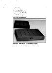
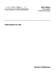
aoua~atal:l s,~au~o
eSl’l Jo# suo!~onJ~SUl
eO~-AVH
I~u!Jaau!/~u..R
o/pn V u! Japea-!
aq.~ ~
KAV-250a
Amplifier
CONTENTS
Page
INTRODUCTION
3
UNPACKING
3
PLACEMENT
3
Cabinetry Considerations
AC Power Guidelines
KrelP Industries, Inc.
45 Connair Road
CONNECTINGTHE KAV-250a
TO YOUR SYSTEM
Orange, CT 06477-3650 USA
Input and Output Connections
Linking Multiple Amplifiers
Configuring the KAV-250a
for Bridged Operation
TEL 203-799-9954
FAX 203-799-9796
E-MAILkrell @krellonline.com
AM PLIFIER OPERATION
4
4
4
4
5
6
7
On/Off and Stand-by Operation
SystemNoise Considerations
"7
7
WARRANTY
8
RETURN AUTHORIZATION
PROCEDURE
9
SPECIFICATIONS
12
ILLUSTRATIONS
Page
THE KAV-250a BACKPLATEAND
CONNECTIONS FOR BRIDGED
OPERATION
®Industries,Inc. All rights reserved
©1997byKRELL
6
P/N19608,0230,0000
CE Marking
Unpacking
This product complieswith the EMC
directive (89/336/EEC) and the low-voltage
directive (73/23/EEC).
1. Openthe boxandremove
the top layer of
foam.Youwill seetheseitems:
1 KAV-250a
1 ACpowercord
1 packetcontainingthe Owner’s
Introduction
Referenceandthe Warranty
Registration Card .~ ,’~ x ~’ ~x~
Thankyou for your purchaseof the Krell
If any of theseitems are n~cld~ed,
KAV-250a.
To obtain the best performance NOTE:
from your KAV-250a
amplifier, pay careful pleasecontactyour authorizedKrefl dealer
attentionto its placement,
installation, and or distributor immediately
for assistance.
operation. A thorough understanding of
thesedetails will help insure satisfactory 2. Carefully removethe unit and accessories fromthe box. Remove
the protecoperation andlong life for the KAV-250a
tive plastic wrapfromthe unit.
and related systemcomponents.
NOTE:Saveall packingmaterials. If you
THERE ARE NO USER-SERVICEABLE must ship your ~V-250ain the future,
PARTSINSIDE ANY KRELL PRODUCT. repackthe unff in its original packaging
to
preventtransit damage.
Pleasecontact your authorizeddealer,
distributor, or KrelP, if you haveany
questionsnot addressedin this referPlacement
ence manual.
WARNINGS
Theamplifier mustnot be located whereit
could be exposedto dripping or splashing
fluids.
Beforeyou install the KAV-250a
into your
system,reviewthe following guidelines to
choosethe location for the KAV-250a.
This
will facilitatea clean,trouble-free
installation.
TheKAV-250a
doesnot require any type of
specialrackor cabinetfor installation.Forthe
dimensions of the KA V-250a, see
Specifications
on page12.
Placethe KAV-250a
amplifier on a firm level
surface awayfrom dirt or moisture. When
using customracks or cabinetry, keepin
mindthe weightandventilation requirements
for this amplifier.Ideally,theamplifiershould
KRELL® KAV-250a
English Page3 of 12
Placement,
continued
be placedas close to the speakersas possible. Runlong balanced interconnect
cablesto the amplifier andkeepthe speaker cable length to a minimum.Speaker
cable adds impedanceto the load the
amplifier must drive, regardless of the
cable’sgauge.All Krell amplifierswill drive
the lowest impedances
with ease, but when
impedanceis added due to long cable
lengths, amplifier poweris wastedin the
cable. Long speaker cables reduce the
maximum
power that can be delivered to
the speakers.
CabMetryConsiderations
Connecting the KAV-250a
to Your System
WARNING
Whenmakingconnections to this component or any other, makesure the power
amplifieris Off andthe preamplifieris in the
Muteor Stand-bymode.Makesure all cable
terminationsare of the highestquality, free
fromfrayedends,shorts,or coldsolderjoints.
Input and Output Connections
To preventthe introduction of humor other
noise into the system,organizeall wiring
betweenthe KAV-250pand other system
components
neatly. SeparateACwires from
audiocables.
The KAV-250a
amplifier can becomequite
warmundernormaloperation. Install the
KAV-250a
in a location that providesunob- 1. Connectthe cables from your speakers
to the outputterminalsof the amplifier.
structedventilation.If youplacethe amplifier in a closedcabinet,extraventilation such
TheKAV-250a
amplifier utilizes fiveas modified shelf spacing maybe neceswaybinding post speakerterminals for
sary. In extremeinstances,small fans help
the left andright channels.Thespeaker
to removing excess heat from enclosed
terminalsacceptspadelugs, barewire,
spaces.In general,whenthe front andrear
bananaplugs, or pins. Thered terminals
of a cabinetis open,the amplifier hasadeare usedfor positive connectionsand
quateventilation with two inchesof clearthe black terminalsare usedfor the negance on each side and eight inches of
ative connections.
clearanceaboveandbelow.
2. Connectthe interconnect cables from
yourpreamplifierto the input terminalsof
ACPowerGuidelines
theamplifier.
For best performance,Krell ® recommends TheKAV-250a
amplifier is equippedwith
using a dedicatedACpowerline rated at a
balancedandsingle-endedinputs. The
minimum
of fifteen ampswith the KAV-250a
balancedinputs use three pin XLRconamplifier. For maximum
poweroutput, the
nectorsandthe single-endedinputs use
KAV-250a
should be operatedfrom a dediRCAconnectors.Krell ® recommends
the
cated twenty ampAC power line. The
use of balancedinterconnects.Balanced
KAV-250a
amplifier shouldonly be operated
interconnects
not onlyhavethe ability to
with the powercord supplied.Pleaseconsult
yourdealer,distributor,or Krell®beforeusing
anydevicesdesigned
to alter or stabilize the
ACpowerfor the KAV-250a.
Page4 of 12 English
® KAV-250a
KRELL
minimize sonic loss but also haveimmunity to inducednoise,especiallyfor installations using long cable lengths..Balanced connections have 6dB more gain
than single-ended connections. When
level matchingis critical, keepthis specification in mind.
WARNING
Useonly oneset of inputs to the amplifier at a
time. TheKAV-250a
amplifier is shippedwith
shorting pins in the XLRinputs. Thesepins
should remain in the XLR inputs if the
KAV-250a
amplifier is operatingin the singleendedmode.Whenthe shorting pin is inserted, pins 1 and 3 are shorted together. The
shorting pins mustbe removed
to connectthe
KAV-250a
amplifier for balancedoperation.
TheXLRpin configuration is describedbelow:
Pin 1
Ground
°)
Pin 2
Non-inverting(0
°)
Pin 3
Inverting (180
3. Insert the ACpowercord into the receptacle located on the back of the KAV-250a
amplifier. Insert the other endinto the AC
wall receptacle.
4. Theamplifier is now~eadyfor operation.
See Amplifier Operation, on page 7.
Linking Multiple Amplifiers-TM Ti)
Multi AmpThroughput
(MAT
For systemscontaining multiple amplifiers,
TM(MAT
~M) simplifies
Multi AmpThroughput
~-Mprovides a daisy-chain
installations. MAT
system option that reduces installation
complexity and cabling requirements. To
use this option, connectthe outputs of the
amplifier (either balancedvia XLRor singleendedvia RCAconnectors) to the inputs of
another amplifier. The output of the first
amplifier sendsthe preamplifier signal to
the next amplifier in the chain.
12 VDC REMOTEPOWERIN
This input accepts12 volt poweron/off signals from other Krell components,as well
as from other devices that incorporate a 12
volt poweron/off trigger output. This allows
for remoteturn on/off of the KAV-250a
with
the poweractivation of another Krell component as well as with with other components usedin a custominstallation.
12 VDC REMOTE POWEROUT
This output sends12 volt poweron/off signals to other Krell components,as well as
other devices that incorporate a 12 volt
poweron/off trigger input. This allows for
remoteturn on/off of the KAV-250a
with the
power activation of another Krell compo~
nent as well as with other components
used
in a custominstallation,
NOTE:Consult the owner’s manual of any
device usedin a custominstallation to take
full advantageof the remote capability of
the KAV-250a.
KRELL® KAV-250a
English Page5 of 12
Configuring the KAV-250a
for Bridged Operation
TheKAV-250amaybe configured to operate
in a bridgedmode.When
bridged, the amplifier will deliver 1000watts to an 8 ohmload. To
implement
this configuration:
1. Turn the KAV-250a
off.
2. Locatethe red switch on the backof the
amplifier and slide it from the NORMAL
position to the BRIDGED
position. The
numeral2 will appearon the switch, when
the switch is in the BRIDGED
position.
Connectthe interconnect cable to the
BRIDGED
input, either balancedvia the
XLRconnector or single-ended via the
RCAconnector. Do not use both inputs
simultaneously. Connect the speaker
cables to the speakerterminals labeled
BRIDGED(-)and BRIDGED(+).The
lifier is nowreadyfor bridgedoperation.
THE KAV-250a BACKPLATEAND CONNECTIONSFOR BRIDGED OPERATI()N
NOTE:The KAV-250amay be configured for bridged operation using either
a single-ended input (1) or a balanced input (2)
1
2
3
4
5
6
7
8
Single-ended input, for connection to a preamplifer
Balancedinput, for connection to a preamplifier
5-way binding post speaker terminals
Redswitch in bridged position, (with the numeral 2 displayed)
Single-ended output, for connection to another amplifier
Balanced output, for connection to another amplifier
12 volt trigger input
12 volt trigger output
1
RIGHT
OUTPUT
C)
2
LEFT
OUTPUT
(BRIDGED (~
~ED LEFT ~NPUT)
RIGHT
KAV-250a
PowerAmplifier
® Industries, Inc.
KRELL
45 Connair Road
Orange, CT 06477-3650
USA
No user serviceable parts inside
VOLTAGE
FUSE
100-120MDA-20
200-240MDA-12
LINE IN
0
Q 50/60Hz
12VDC
REMOTE
POWER
0
MADE
IN USA
33
Page 6 of 12 English
KRELL® KAV-250a
Amplifier Operation
SystemNoise Considerations
critical whenconIt is easyto understand
the operationof the ACgroundingbecomes
necting
high
performance
audiocomponents.
KAV-250a
amplifier. However,great care
needsto be exercisedwhenoperatinga sys- Whenmixing and matching audio compotemthat includes the KAV-250a,
becauseof nents,eachwith their owngroundpotential, a
low frequencyhummayoccurin oneor both
the amplifier’s enormouspoweroutput.
Switchingbetweenactive sourceswithout speakers.This often occurswhenintroducing
into a system.
mutingthe preamplifier output, or bump- ¯ a newcomponent
ing/miscuinga cartridge, cangeneratelarge If there is a low frequencyhumemanating
transients at low frequencies.TheKAV-250a from the speakers when the KAV-250a
amplifier maygenerateenoughpowerwith amplifier is placedinto the system,follow
thesetransients to damage
mostloudspeak- thesesimpletrouble-shootingsteps before
ers. All switchingof sourcesshouldbe done contactingyourauthorizedKrell dealer,diswiththe preamplifier
level eithermuted
or fully tributor,or Krell®:
attenuated.Donot change
inputsto the ampli1. Checkall input andoutput connections,
fier whiletheamplifieris On.
makingsure they are of soundconstrucNOTE:Care must be taken whensetting
tion. Withthe amplifier Off, remove
the
high playback levels. Becauseof their
interconnect
wiring andturn the amplifier
tremendous
reserve of clean power,Krell
On.If the humdisappears,
turn the ampliamplifierscansafely drive speakers
to highfier Off andreinsert oneof the intercdner soundpressurelevels than other amplinect cables.Thenturn the amplifier back
fiers. Alwaysturn the level downat the first
On.If the humreappears
with oneor both
sign of speakerdistress.
interconnectsreinserted,there maybe a
defective cable. Havethe interconnect
cabling checkedbeforeproceeding.
On~Offand StandbyOperation
2. If the interconnectsproveto be sound,
Whenpoweringup any system, amplifiers
youmaybe experiencinga groundloop.
shouldalwaysbeturnedonlast andturnedoff
This canoften be easily eliminated.Confirst.
tact yourauthorized
Krell dealer,distribu®.
tor,
or
Krell
1. Pressthe powerbuttonon the front panel
of theamplifier.Youwill heara click. The
amplifieris readyfor operation.
2. Withthe preamplifierin the Muteposition,
or ’the volumecontrol fully attenuated,
select a source.Turnthe volumecontrol
upto thedesiredlisteninglevel.
turning the systemoff, lower the
3. When
volumeof the preamplifiercompletelyor
placeit into the Muteor Stand-byposition. Switchthe amplifier to Stand-by
by
pressingthe powerbutton. It is nowsafe
to turn off the rest of the system.
English Page7 of 12
KRELL® KAV-250a
Warranty
Thewarrantyfor this Krell productis valid
only in the countryto whichthe productwas
Krell® warrantsthis productto be free from originally shipped,throughthe authorized
defects in material or workmanship
for a Krell distributor for that country,andat the
periodof five yearsfor circuitry andthree factory. Theremaybe restrictions on or
to Krell’s warrantybecause
of regyears for all mechanicalcomponents
from changes
ulations
within
a
specific
country.
Please
the original date of purchase.Shouldthis
productfail to performat anytime duringthe checkwith your distributor for a complete
of the warrantyin your counwarranty,
Krell®will repairit at nocostto the understanding
try.
owner,exceptas set forth in this warranty.
Transferof warrantyto a second
owneroccurs Freightto the factoryis yourresponsibility.
automatically.PleasecontactKrell® to have Return freight within the United States
the nameon the warrantychanged.Transfer (U.S.A.)is includedin the warranty.If you
of warrantydoesnot extendthe durationof havepurchasedyour Krell product outside
the original warrantyperiod.
the U.S.A.andwishto haveit servicedat
NOTE:This warranty does not apply to the factory, all freight and associated
chargesto the factory are yourresponsibilidamage
causedby acts of Godor nature.
ty. Krell®will payreturnfreightto the U.S.A.Thewarrantyperiod begins on the date of basedfreight forwarder of your choice.
retail purchase
as notedon the retail sales Freight andother chargesto ship the prodslip providedby an authorizedKrell dealer uct from the freight forwarderto you ai’e
or distributor, or on the warranty
registration alsoyourresponsibility.
®.
cardsentto Krell In the eventthat an adequateproof of purchase
dateis unavailable, Theoperating voltage of this product is
the warrantyperiod will beginon the date determinedat the factory andcan only be
by an authorizedKrell distributor or
the productwasoriginally shippedfrom the changed
factory. Thewarrantydescribedin this para- at the factory.Thevoltagefor this productin
for six months
graphshall bein lieu of anyotherwarranty, the U.S.A.cannotbe changed
date.
express
or implied,including,but not limited fromthe original purchase
to, anyimplied warrantyof merchantability Anyunauthorized
voltageconversion,
disor fitness for a particularpurpose.
Thereare assembly,component
replacement,perfono Warrantieswhich exceedbeyondthose ration of chassis,updates,or modificadescribedin this document.
If this product tions performed
to the productwill void
doesnot performas warrantedherein, the the warranty.
owner’ssole remedyshall be repair. In no
eventwill Krell® be liable for incidentalor
consequentialdamages
arising from purchase,use, or inability to usethis product,
evenif Krell® hasbeenadvisedof the possibility of suchdamages.
KRELL® KAV-250a
English Page 8 of 12
please contact your authorized Krell
dealer, distributor, or the Krell Service
Department
for assistance.
®
IMPORTANT:
If you befieve thero is a prob- Krell is not responsible for any damage
lemwith yourunit, pleasecontactyourdeal- incurredin transit. Krell®will file claimsfor
er, distributor, or the Krell factory immedi- damagesas necessary for products damately Donot return any unit to KrelP for agedin transit to the factory. Theowneris
for filing claimsfor shippingdamrepair without first discussingthe problem responsible
ages
that
occur
duringthe return shipment.
and obtaining a Return Authorization
Number.
Replacement
parts and/or productswill be
furnished
on
an exchangebasis only; any
To return a product, the owner
parts and/orproductsreturnedto Krell® for
is requiredto:
®.
exchange
become
the propertyof Krell
¯ Obtain a Return Authorization Number
(R/A number) and shipping address Noexpressedor implied warranty is made
for any Krell productdamaged
by accident,
fromthe Krell ServiceDepartment.
abuse,misuse,natural or personaldisaster,
¯ Insureandacceptall liability for loss or or unauthorized
modification.
damage
to the product during shipment
®
to the Krell factory andprepayall ship- In the eventthat Krell receivesa product
ping charges.The product mayalso be for warrantyservice whichhas beenmodihanddeliveredif arrangements
with the fied in anywaywithoutKrell authorization,
all warrantieson that productwill be void.
Service Departmenthavebeenmadein
advance.Proof of purchasemaybe re- Theproductwill be returnedto original facquiredfor warrantyvalidationat the time tory layout specifications at the owner’s
expensebefore it is repaired. All repairs
of handdelivery.
requiredafter the producthasbeenreturned
¯ Usethe original packaging
to insure the to original factory specification will be
safetransit of the productto the factory, chargedto the customer,at current parts
dealer, or distributor. Theuse of any andlabor rates.
packaging
materialotherthanthe original
packagingmaterials is not recommend- To contact the Krell ServiceDe~artment
ed. Krell® may,at its discretion,returna
TEL
203-799-9954
product in newpackagingandbill the
Monday-Friday
ownerfor suchpackagingif the product
9:00 AMto 5:00 PMEST
received by Krell ® wasboxedin nonFAX 203-799-9796
standardpackagingor if the original
E-MAILkrell @krellonline.com
packagingwasso damaged
that it was
unusable.If Krell ® determinesthat new KAV-250a
packaging
is required, the ownerwill be PRODUCT
SERIAL NUMBER
notified beforethe productis returned.
To register your product for warranty benefits,
To purchase additional packaging,
complete and return
the Warranty
ReturnAuthorization
Procedure
Registration Card enclosed in the shipping
boxwithin 15 days of purchase.
Page9 of 12 English
KRELL® KAV-250a
Krell®Industries,Inc.
45 Connair Road
Orange, CT 06477-3650USA
KAV-250a
TEL 203-799-9954 FAX 203-799-9796
E-MAIL
krell @krellonline.com
Specifications
FREQUENCYRESPONSE
20Hz-20KHz +0.0,-0.1 dB
.4Hz-170KHz +0.0, -3.0dB
SIGNALTO NOISE RATIO
-118dB"A" weighted
DISTORTION
1KHz 0,06% THD
20KHz 0.25% THD
GAIN
26.4dB
INPUTSENSITIVITY
2.15 Vrms
INPUT IMPENDENCE
100K ohms
OUTPUTVOLTAGE
Peakto peak 138 V
RMS
49 V
OUTPUT
POWER,
each channel driven
8 ohms
1,000W (bridged)
8 ohms
4 ohms
250 W
500 W
POWERCONSUMPTION
Idle 210 W
Max. 1850 W
DIMENSIONS
19wx 6.3h x 15.3din.
48.3w x16h x 38.9d cm
WEIGHT
Shipped
57 Ibs., 25.9kg
Unit only
43 Ibs., 19.5kg
All operationalfeatures,functions,specifications,and
3oliciesaresubjectto change
withoutnotification.