1
ExMax-.. and RedMax-.. extra information EL - size S
E X P L O S I O N P R O O F
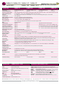
Error indication
Error/Symptom
Reason
Solution
01
Actuator does not work
LED does not lights
l
l
No power supply attached
The actuator is operated beyond ex-prevention
ambient temperature specifications and the internal
temperature sensor did irreversibly shut down
operations
l
l
Attache power supply and turn on
Because of inadmissable operation the actuator drove out of safety
relevant reasons into an irreversible condition and must be exchanged.
Accompanying new installation the ambient temperature has to be
reduced accordingly
02
Actuator does not work
LED lights red
l
The actuator is operated by a too high ambient
temperature and the internal temperature sensor
responded
l
Shut off actuator and let temperature decrease, reduce ambient
temperature by suitable measures e.g. ventilation or other mounting
position of the actuator
03
Actuator does not work
LED lights green
l
l
3-Pos control signal is wired on both entrances
Required torque is greater than actuators torque
l
l
l
Control signals are not attached or attached on a
wrong conductor
Actuator is incorrect mounted and is blocked by an
external stop unit
l
Readjust/correct circuit
Adjust a higher torque at the actuator if possible otherwise exchange
for a type with higher torque.
Examine rule and adjusting signal in accordance with attached diagram
l
Actuator is clocked with more than 20 impulses <0,5
per sec. and therefore adjusted into suspend mode
l
l
Interchanged supply lines
l
Wire 1 must be (-, N) and wire 2 (+, L)
l
l
Dismount actuator and testdrive without load for operability. Install
actuator accordingly that the power transmissions runs without external
blockade or torsion
Switch off supply voltage for at least 2 sec. thereby a reset is conducted
Readjust controller in order to extend control pulses
04
Acuator does not work
LED is red blinking
l
The actuator has been mounted by temperatures
of less than -20°C and did not reach is operating
temperatur of at least -20°C.
l
l
Ensure that a constant voltage supply on conductor 1--2 is existing.
Wait until the required operating temperature is achieved by the actuators
internal heating system.The actuator will start operating independently
05
Spring return funktion is 10 sec./90°,
should however amount to 3 sec./90°
l
Bridge 2 --5 is not established
l
Bridge conductor 2 of the constant voltage supply with conductor 5
06
Spring return funktion is 3 sec./90°,
should however amount to 10 sec./90°
l
Bridge 2 --5 is established
l
Disconnect bridge
07
Actuator does not start after more than
2 briefly following adjusting functions
in the 3 sec. mode where set
l
The maximal permissable cyclic duration of 10%
ED was not complied to, the actuator is in a safety
disconnection mode
l
Wait approx.1 minute until internal electronics cool down to operating
temperature.
08
Y-drive in the 3-pos mode can not gear
into intermediate positions
l
The conversion of constant mode on 3-pos-modus
was not set
l
Recalibrate the actuator in accordance with assembly instructions
09
Actuator sits diagonally on the squared
damper shaft
l
The actuators have an angle of rotation of 95°
inclusive 5° pre-tention. While assembling the preloading was not considered
l
Dismount actuator of the damper, use the enclosed socket wrench to
draw up approx. 5° over the hand operated control device before
remounting on the damper shaft. Consider additional information ME
of the assembly instructions
10
Actuator is with clamp stand KBS
actuated installed onto damper shaft
and does only partly or not at all drive
l
Provided that the electrical basic conditions specified
above are fullfilled, the anti- twist plate could be so
installed that the actuator blocks itself due to the
twisted and not centric shaft connection and therefore
interlocks
l
Loosen the anti-twist plate and remount that the actuator can implement
an easy oscillationg motion over its angle of rotation
11
A modulating actuator (Y) works with
reduced angle of rotation and already
reaches its end positions before O V/4
mA, respectively before 10V/20mA.
l
At start up no self adjustment of angle of rotation
was accomplished
l
Accomplish self adjustment of angle of rotation in accordance with
assembly instruction
12
LED flashes irregularly and actuator
does not work
l
Actuator does not receive sufficient supply voltage
l
Increase line cross section or increase tension at the transformer/power
suply unit
l
Cable to long, voltage drop in the supply line to large
l
Increase line cross section or increase tension
M.EZ-01.05-S-en-Zusatzinfo EL
2008-01-16
Schischek GmbH Germany D-90579 Langenzenn, Mühlsteig 45, Gewerbegebiet V, Tel. ++49 (0)9101-90810, Fax ++49 (0)9101-908177, Email [email protected]
www.schischek.com