1
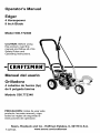
Operator's
Manual
Edger
4 Horsepower
9 Inch Blade
Model
536.772340
CAUTION: Before using
this product, read this
manual and follow all of its
Safety Rules and
Operating Instructions.
- CRRFTSMRN °
Manual del usario
Orilladora
4 caballos
de fuerza
de 9 pulgada
Modelo
(hp)
I&mina
536.772340
PRECAUCI6N: Antes de usar este
producto, lea este manual y siga
todas las reglas de seguridad e
instrucciones de operaci6n.
Sears, Roebuck
F-021102L
and Co., Hoffman Estates,
www.sears.com/craftsman
IL 60179 U.S.A.
TABLE OF CONTENTS
WARRANTY STATEMENT
SAFETY RULES
INTERNATIONAL SYMBOLS
ASSEMBLY
OPERATION
MAINTENANCE
2
3
5
6
10
16
SERVICE AND ADJUSTMENT
19
TROUBLE SHOOTING CHART
22
EDGER REPAIR PARTS
26
ENGINE REPAIR PARTS
34
SPANISH (ESPAI_IOL)
40
PARTS AND SERVICE
BACK COVER
WARRANTY
LIMITED
TWO-YEAR
STATEMENT
WARRANTY
ON CRAFTSMAN
EDGER
For two years from the date of purchase, when this Craftsman Edger is maintained, lubricated, and tuned up according to the operating and maintenance instructions in the owner's
manual, Sears will repair, free of charge, any defect in material or workmanship.
If this Craftsman Edger is used for commercial or rental purposes, this warranty applies for
only 90 days from the date of purchase.
This warranty
• Expendable
does not cover the following:
items which become worn during normal use, such as spark plugs, etc.
• Repairs necessary because of operator abuse or negligence, including bent crank shafts
and the failure to maintain the equipment according to the instructions contained in the
owner's manual.
WARRANTY SERVICE IS AVAILABLE BY RETURNING THE CRAFTSMAN EDGER TO
THE NEAREST SEARS SERVICE CENTER/DEPARTMENT
IN THE UNITED STATES.
THIS WARRANTY APPLIES ONLY WHILE THIS PRODUCT IS IN USE IN THE UNITED
STATES.
This warranty gives you specific legal rights, and you may also have other rights which vary
from state to state.
Sears, Roebuck and Co., D817WA, Hoffman Estates, IL 60179
Engine Exhaust, some of its constituents, and certain vehicle
components
contain or emit chemicals known to the State of
California to cause cancer and birth defects or other reproductive harm.
Battery posts, terminals
and related accessories
contain
lead and lead compounds,
chemicals known to the State of
California to cause cancer and birth defects or other reproductive harm. WASH HANDS AFTER HANDLING.
F-021102L
2
SAFETY RULES
Safe
Operation
Practices
for
Edger.
WARNING:
Look for this
symbolAlert!
to point
important
safety precautions.
It means: "Attention!
Become
Yourout
Safety
Is Involved."
Operating
talARNING:
starting when
setting-up,
To prevent
accidentransporting, adjusting or making repairs, always disconnect spark
plug wire and put wire where it cannot
contact the spark plug.
_
Before Use
• Read the owner's manual carefully. Be
thoroughly familiar with the controls and
the proper use of the Edger. Know how to
stop the Edger and disengage the controls
quickly.
• Do not operate the Edger without wearing
adequate outer garments. Wear footwear
that will improve footing on slippery surfaces.
• Keep the area of operation clear of all persons, particularly small children and pets.
• Thoroughly inspect the area where the
Edger is to be used and remove all foreign
objects.
Fuel Safety
• Handle fuel with care; it is highly flammable.
• Use an approved container.
• Check fuel supply before each use, allowing space for expansion as the heat of the
engine and/or sun can cause fuel to expand.
• Fill fuel tank outdoors with extreme care.
Never fill fuel tank indoors. Replace fuel
tank cap securely and wipe up spilled fuel.
• Never remove the fuel tank cap or add fuel
to a running or hot engine.
• Never store fuel or Edger with fuel in the
tank inside a building where fumes may
reach an open flame.
F-021102L
Safety
Never allow children or young teenagers to
operate the Edger. Keep them away while
it is operating. Never allow adults to operate the Edger without proper instruction.
Do not operate this machine if you are taking drugs or other medication which can
cause drowsiness or affect your ability to
operate this machine.
• Do not use this machine if you are mentally
or physically unable to operate this machine safely.
Always wear safety glasses or eye shields
during operation or while performing an
adjustment or repair to protect your eyes
from foreign objects that may be thrown
from the Edger.
• Do not put hands or feet near or under rotating parts.
Exercise extreme caution when operating
on or crossing gravel drives, walks, or
roads. Stay alert for hidden hazards or
traffic.
Exercise caution to avoid slipping or falling.
Never operate the Edger without proper
guards, plates, or other safety protective
devices in place.
Never operate the Edger at high transport
speeds on slippery surfaces. Look behind
and use care when backing.
Never allow bystanders near the Edger.
Keep children and pets away while
operating.
Never operate the Edger without good visibility or light.
Do not run the engine indoors. The exhaust fumes are dangerous, containing
CARBON MONOXIDE, an ODORLESS
and DEADLY GAS.
Take all possible precautions when leaving
the Edger unattended. Stop the engine.
Do not overload the Edger capacity by attempting to till too deep at too fast a rate.
SAFETY RULES
spect the Edger for any damage, and repair the damage before restarting and
operating it.
Safe Storage
• Always refer to the owner's manual instructions for important details if the Edger is to
be stored for an extended period.
If Edger should start to vibrate abnormally,
stop engine and check immediately for the
cause. Vibration is generally a warning of
trouble.
• Never store the Edger with fuel in the fuel
tank inside a building where ignition
sources are present such as water and
space heaters, clothes dryers, and the like.
Allow the engine to cool before storing in
any enclosure.
Stop the engine whenever you leave the
operating position. Also, disconnect the
spark plug wire before unclogging the
blade and when making any repairs, adjustments, or inspections.
• Keep the Edger in safe working condition.
Check all fasteners at frequent intervals for
proper tightness.
Repair / Adjustments
When cleaning, repairing, or inspecting,
shut off the engine and make certain all
moving parts have stopped.
Safety
• After striking a foreign object, stop the engine. Remove the wire from the spark plug,
and keep the wire away from the plug to
prevent accidental starting. Thoroughly in-
F-021102L
Never attempt to make any adjustments
while the engine is running except when
specifically recommended by the manufacturer.
4
SAFETY RULES
INTERNATIONAL
SYMBOLS
IMPORTANT: Many of the following symbols are located on your unit or on literature supplied with the product. Before you operate the unit, learn and understand the purpose for
each symbol.
Control And Operating Symbols
Slow
Fast
Fuel
Oil
Primer Button
Safety Warning Symbols
WARNING
Thrown Objects.
Keep Bystanders Away.
IMPORTANT
Read Owner's Manual
Before Operating
This Machine.
F-O21102L
WARNING
Rotating Parts. Stop Engine.
Disconnect Spark Wire Before
Making Adjustments.
WARNING
Wear Eye Protection
5
WARNING
STOP
ASSEMBLY
ASSEMBLY
Parts Packed Separately In Carton
1 - Owner's Manual (not shown)
1 - Container Of Oil
1 - Hair Pin
1 - Hair Pin
1 - Container
REMOVE THE EDGER
FROM THE CARTON
glasses or eye
shields
while
as,
WARNING:
Always
wear
safety
sembling the Edger.
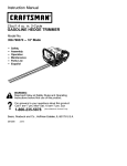
Figure 1 shows the Edger completely
sembled.
of Oil
as-
References to the right or left side of the
Edger are from the viewpoint of the operator's position behind the unit.
1.
Remove the bottle of oil and parts bag
from the carton.
2.
Cut down all four corners of the carton.
3.
Remove the packing material positioned
around the unit.
4.
Roll the Edger out of the carton and
place on a hard level surface.
Figure 1
F-021102L
6
ASSEMBLY
HOW TO RAISE THE HANDLE
1.
2.
Loosen the knobs and raise the upper
handle to the upright position. See
Figure 2. Allow the control rod to swing
freely.
3.
Insert the end of the control rod from
Tighten the knobs. Make sure the
knobs are to the outside of the handles
4.
left to right through the hole in the quill
support arm. Attach with hair pin found
in parts bag. See Figure 3.
When the clutch lever is in NEUTRAL
position, the quill support arm must be
close to the screw as shown in Figure 4.
as shown in Figure 2.
Quill
Support Arm
Control Rod
Upper
Handle
Figure 2
_,
Figure 4
Control
Hair Pin _J
fv
Rod
Quill
t_upport
Arm
Figure 3
F-021102L
7
ASSEMBLY
HOW TO PREPARE THE ENGINE
Fill With Oil
How To Add The Engine
Oil
1. Put the Edger on a level surface.
This Edger was shipped with a container of
SAE30 motor oil. Add this oil to the engine
before operating. To fill the crankcase, remove the oil fill cap/dipstick and add the
SAE30 motor oil. DO NOT OVERFILL.
2. Remove the oil fill cap (Figure 5).
3. Slowly fill the engine crankcase. DO NOT
OVERFILL.
NOTE: The engine may contain a small
amount of oil. When adding oil, frequently
insert the oil fill cap/dipstick and check
the amount of oil in the engine. DO NOT
OVERFILl.
How To Fill With Gasoline
Make sure that the gasoline container is
clean and free from dust or other foreign material. Never use gasoline that could be stale
from long periods of storage.
Oil Recommendations
1. Remove the fuel cap.
Only use high quality detergent oil rated with
API service classification SG. Select the oil's
SAE viscosity grade according to your expected operating temperature. Although multi-viscosity oils (5W30, 10W30, etc.) improve
starting in cold weather, these multi-viscosity
oils will result in increased oil consumption
when used above 40 degrees. Check the
engine oil level more frequently to avoid possible engine damage from running the engine low on oil.
2. Fill the fuel tank with clean, fresh, unleaded grade automotive gasoline.
fuel container. Do not smoke
WARNING: Always use a safety
when adding the fuel mixture to
the engine. When inside an enclosure,
do not fill the fuel tank. Before you add
the fuel mixture, stop the engine. Let the
engine cool for several minutes.
NOTE: ENGINES WHICH ARE CERTIFIED
TO COMPLY WITH CALIFORNIA AND US
EPA EMISSION REGULATIONS FOR
ULGE ENGINES, are certified to operate
on regular unleaded gasoline. Include the
following emission control system(s):
EM, TWC (if so equipped). Include any
user adjustable features - therefore no
other adjustments are needed.
,_
32 °
Colder
5W30
I
_Warmer
SAE30
"_
Fuel Cap
_igure
Oil Fill Cap
F-021102L
8
5
ASSEMBLY
_- CHECKLIST
For the best performance and satisfaction
from this quality product, please review the
following checklist before you operate the
Edger:
_'
All assembly
completed.
instructions
have been
_'
Check carton. Make sure no loose
parts remain in the carton.
_'
All fasteners
ened.
have been properly tight-
As you learn how to use the Edger, pay extra
attention to the following important items:
_'_'
Engine oil is at proper level.
_'_'
Fuel tank is filled with a fresh, clean,
regular Unleaded gasoline.
_'_'
Become familiar and understand the
function of all controls. Before your
start the engine, operate all controls.
IMPORTANT: This unit is equipped with an internal combustion engine and must not be
used on or near any unimproved forest-covered,
brush-covered
or grass-covered
land
unless the engine's exhaust system is equipped with a spark arrester meeting
applicable local or state laws (if any). If a spark arrester is used, it must be maintained in
effective working order by the operator.
In the State of California the above is required by law (Section 4442 of the California
Public Resources Code). Other states may have similar laws. Federal laws apply on federal lands. A spark arrester/muffler is available through your nearest Sears Service Center (see the REPAIR PARTS section in this manual).
NOTE: Actual sustained horsepower will likely be lower due to operating limitations and environmental factors.
F-021102L
9
OPERATION
KNOW YOUR EDGER
READ THE OWNER'S
MANUAL AND ALL SAFETY RULES BEFORE YOU OPERATE the
Edger. To familiarize yourself with the location of the controls, compare the illustrations with
your Edger. Save this manual for future reference.
ENGINE
Clutch Lever
I_
Throttle
_I_
Choke
Control Rod
Blade Guard
VIEW OF BLADE AREA
Starter
Handle
Index Lever
Adjustable Rear Wheel
Adjustable Front Wheel
Blade
Figure 6
Throttle Control (if equipped) - Controls the engine speed.
for curb-hopping.
Clutch
equipped with an easy pull recoil starter.
Lever-
Recoil
Use to start and stop the
Starter
Handle
- The engine is
Blade Guard - Use to prevent stones or
other material from being thrown at the operator.
blade and control the depth of cut.
Adjustable
Rear Wheel - Right rear
wheel is adjustable to level the Edger when
edging along a curb (curb-hopping).
Index
Lever-
Permits adjustment from
the edging (vertical) position to the trimming
Adjustable
Front Wheel - Front wheel
is adjustable from side-to-side
for balance.
The front wheel can also be adjusted down
(horizontal) position. To change position, pull
the index lever and rotate the quill assembly
to the desired angle or position.
EYE PROTECTION
the
Edger can
resultthrown
in foreign
WARNING:
Debris
from
objects being thrown into the
eyes, which can cause severe eye damage. Always wear safety glasses or eye
shields when operating the Edger.
Always wear safety glasses. If you wear eye
glasses, put a Wide Vision Safety Mask over
your eye glasses.
F-021102L
,_
10
OPERATION
HOW TO STOP THE EDGER
Move the clutch lever back to the DISENGAGED position. Then, move the
throttle control to SLOW, then to STOP
(if equipped) See Figure 7.
Clutch Lever
_
WARNING: Never leave the
EDGER unattended while the
engine is running. Always disengage the cutting blade and stop the
engine.
Figure 7
I
Throttle
HOW TO USE
THE THROTTLE CONTROL
1.
During normal use, run the engine at full
speed.
2.
Move the throttle control up to increase
engine speed, or down to decrease engine speed (see Figure 8).
ltl.o.o.o
Figure 8
HOW TO USE
THE CLUTCH LEVER
1.
Start the engine.
2.
To engage the cutting blade, move the
clutch lever forward (see Figure 9).
3.
Select the edging depth you need. There
are five selections down to approximately 2-3/4 inches deep.
Clutch Lever
NOTE: For deep edging, first cut at shallow
depths. Then, cut at greater depths until
the desired depth is obtained.
F-021102L
N i1 1
Figure 9
11
OPERATION
HOW TO USE THE INDEX LEVER
1.
Stop the engine and disconnect the
spark plug wire from the spark plug.
2.
Loosen the front wheel knob shown in
Figure 10. Slide the front wheel all the
way to the right side.
3.
Securely tighten the front wheel knob.
NOTE: To prevent the blade from hitting the wheel while trimming, make
sure the front wheel is set in the exFront Wheel
Knob
treme right position.
4.
Disengage the index lever (see
Figure 11). Move the index lever to the
notch marked 90 ° .
Front Wheel
5.
Reconnect the spark plug wire to the
spark plug.
6.
Start the engine.
7.
Figure 10
Move the clutch lever to the desired trimming height.
running, never
leave
Edger.
WARNING:
While
the the
engine
is
Before you adjust the wheels or
change the blade position, always disengage the cutting blade and stop the
engine.
_
F-021102L
/
Index Lever
Figure 11
12
OPERATION
HOW TO USE THE CURB-HOPPING
FEATURE
wheel until the front wheel is level with
Because the front wheel and the right rear
wheel are adjustable, the Edger can be used
on uneven surfaces, such as the curb shown
in Figure 12. Set the wheel positions as follows.
1.
Stop the engine.
2.
Disconnect the spark plug wire from the
spark plug.
3.
Loosen the front wheel knob.
4.
Slide the front wheel to the best position to clear the curb and balance the
unit.
5.
Securely tighten the front wheel knob.
6.
Use the curb height adjust lever to
lower the front wheel. Lower the front
the left rear wheel and the unit is setting
on the curb as shown in Figure 12.
7.
Loosen the rear wheel knob.
8.
Lower the right rear wheel until the
Edger is level and the left rear wheel is
on the curb.
9.
Securely tighten the rear wheel knob.
10. Connect the spark plug wire to the spark
plug.
_
rotating
blade.
Theaway
bladefrom
canthe
ARNING:
Keep
cause injury.
Blade Guard
Front
Wheel Knob
Support Rod
Rear Wheel Knob_
Front Wheel
Figure 12
F-021102L
13
OPERATION
HOW TO STOP THE ENGINE
1. To stop the engine, move the clutch lever
all the way back to the DISENGAGED
position.
9. Quickly pull the recoil starter handle. DO
NOT allow the starter rope to snap back.
Let the starter rope slowly rewind. If engine fails to start after three pulls, push
primer button two times and again pull
the recoil starter handle.
2. Then, move the throttle control lever to
the STOP position (Figure 13).
HOW TO START THE ENGINE
IMPORTANT: Before you start the engine,
operate the controls several times. Make
sure all controls move freely.
1. Check the oil.
2. Fill the fuel tank with regular unleaded
gasoline. Make sure the gasoline is
clean. Leaded gasoline will increase deposits and shorten the life of the valves.
NOTE: Do not use gasohol or methanol.
not use premium unleaded gasoline.
,_
Choke
Figure 13
Do
10.When the engine starts, move the throttle
control lever up (FAST position) to increase speed or down to decrease
speed. During normal use keep the
throttle in the FAST position.
gasoline container.
Do not
WARNING:
Always use
a safety
smoke when adding gasoline to
the fuel tank. When inside an enclosure,
do not add gasoline. Before you add
gasoline, stop the engine and let the engine cool for several minutes.
11. If the engine does not start in 5 or 6 tries,
See the "Problem and Repair" Instructions.
3. Make sure the spark plug wire is connected to the spark plug.
NOTE: The cutting blade speed is controlled by the engine speed. To reduce the
cutting blade speed, push down on the
throttle control lever. To increase the cut-
4. Pull the clutch lever all the way back to
raise and disengage the blade.
ting blade speed,
control lever.
5. Move the throttle control lever (if
equipped) to the FAST position
(Figure 13).
,_
6. Move the choke control lever to the
CHOKE position (Figure 13).
carbon
up on the throttle
indoors or inNever
a poorly
ventilated
WARNING:
run the
engine
area. Engine exhaust contains
monoxide, an odorless and
deadly gas. Keep hands, feet, hair and
loose clothing away from any moving
parts. Avoid the muffler and surrounding areas. Temperatures can exceed 150
degrees.
7. To start engine, hold the recoil starter
handle firmly with your right hand.
8. Hold the edger handle firmly with your left
hand.
F-021102L
pull
14
OPERATION
EDGING TIPS
• Edging is best performed when conditions
are dry. If the soil is to wet, dirt becomes
packed around the blade causing premature belt wear and decreased performance.
• If dirt does become packed around the
blade, stop the engine and remove the
wire from the spark plug. Remove the
packed dirt and debris from the blade.
• For deep edging, first cut at shallow
depths. Then, cut at greater depths until
the desired depth is obtained.
• For uniform edging, make sure the blade
guide rides on the surface.
• Edging can be customized by varying the
number of passes and by the distance the
blade is from the surface.
manual. Know location and
WARNING: Read the Owner's
functions of all controls. Keep
all safety devices and shields in place.
Never allow children or uninstructed
adults to operate Edger. Shut off engine
before unclogging blade or making repairs. Keep bystanders away from machine. Keep away from the blade all rotating parts, which cause injury.
F-021102L
15
MAINTENANCE
CUSTOMER RESPONSIBILITIES
SERVICE
RECORDS
Fill in datesas you
completeregular
service,
Before
Each
use
Every Every
Often
10
25
Hours Hours
Before
Each
Season
Lubricate Wheel
Axles
Before
SERVICE
Storage
DATES
v'
v'
Change Engine Oil
v'
Check Spark Plug
v'
Tighten All Fasteners
Lubricate Quill Rod/
tube
v'
v'
PRODUCT SPECIFICATIONS
v'
GENERAL RECOMMENDATIONS
Horse Power:
4
The warranty on this Edger does not cover
items that have been subjected to operator
abuse or negligence. To receive full value
from the warranty, the operator must maintain the Edger as instructed in this manual.
Displacement:
9.02 cu. in.
(148 cc.)
Some adjustments must be made periodically to properly maintain your Edger.
Model No.:
536.772340
Date Of Purchase:
Oil Capacity:
Spark Plug Gap:
F-021102L
All adjustments in the Service and Adjustments section of this manual must be
checked at least once each season.
21 oz. SAE-30W
0.030 inch
16
MAINTENANCE
LUBRICATION
4.
Remove the oil fill cap (see Figure 14).
Fill the engine crankcase. Pour slowly.
Do not overfill. See "Product Specifications" for amount and type of oil. Install
the oil fill cap.
5.
Connect the spark plug wire to the spark
plug.
After each 25 hours, apply a small amount of
engine oil to all moving parts, particularly the
wheels.
How To Change
The Engine
Oil
Change the oil in the engine crankcase after
each 25 hours of use.
Oil Fill Cap
NOTE: The oil will drain more freely when
the engine is warm.
1.
Disconnect the spark plug wire from the
spark plug.
2.
Remove the oil drain plug. Drain the oil
into a flat pan.
3.
After draining all the oil, install and tighten the oil drain plug.
Oil Drain
Plug Figure 14
HOWTO CHANGETHE AIR FILTER
CAUTION: Never run the engine without
the air filter. A defective air filter will
Service the air filter once a year; more often
in dusty or dirty conditions. All engines have
an air cleaner cartridge. In addition, some
engines have a pre-cleaner.
cause a loss of engine power. If dirt or
dust enters the engine through the carburetor, the result will be excessive wear or
damage to the engine. Replace a damaged or clogged air cleaner immediately.
1.
Disconnect the spark plug wire from the
spark plug.
2.
Loosen the screws and remove the
cover (see Figure 15).
3.
Remove pre-cleaner (if equipped) and
cartridge carefully to prevent debris
from entering carburetor.
4.
Screw
Cover
To clean pre-cleaner (if equipped), separate it from cartridge and wash in liquid
detergent and water. Air dry thoroughly.
Do not oil. Re-install dry pre-cleaner on
clean cartridge.
Pre-cleaner
CAUTION: Do not use pressurized air
or solvents to clean cartridge. Pressurized air can damage cartridge; solvents will dissolve cartridge.
5.
Re-install clean (or new) air cleaner assembly in base.
6.
Replace cover and tighten screws.
Connect the spark plug wire to the spark
plug.
F-021102L
Cartridge
7.
Figure 15
17
MAINTENANCE
SPARK
PLUG
Check the spark plug every 25 hours. Replace the spark plug if the electrodes are
pitted, burned, or if the porcelain is cracked.
moval. Tighten the spark plug to a torque
of 15 foot-pounds.
Feeler Gauge
0.030"
Make sure the spark plug is clean.
Clean the spark plug by carefully scraping the electrodes (do not sand blast or
use a wire brush).
2. Check the spark plug gap with a feeler
gauge.
Spark Plug
Before installing the spark plug, coat
the threads lightly with oil for easy re-
CARBURETOR
Figure 16
ADJUSTMENT
Never make unnecessary adjustments to the
carburetor. The carburetor was set at the
factory to operate efficiently under most applications. However, if adjustments are required, we recommend you contact your
nearest Sears Service Center.
nor is set atThe
the engine
factory. goverDo not
WARNING:
change the governor setting.
Over speeding the engine above the factory setting can be dangerous. If you
think the engine governor needs an adjustment, contact your nearest Sears
Service Center.
F-021102L
18
SERVICE
AND ADJUSTMENT
HOW TO REMOVE THE BELT
The belt made of a special compound. If the
belt becomes worn or breaks, replace the
belt with an original equipment belt.
4.
Disconnect the spark plug wire from the
spark plug.
2.
5.
Loosen, do not remove, the screw that
holds the belt guide. Then, move the
belt guide away from the belt.
Remove the two screws
from the belt
guard (see Figure 18).
Pull the clutch lever back to release the
tension from the belt.
Remove the two screws and spacers
from the top of the engine pulley cover.
Remove the engine pulley cover (see
Figure 17).
6.
Remove the old belt from the engine
and quill assembly pulleys. Replace with
an original equipment belt.
7.
To install a new belt, reverse the above
steps.
Belt Guard
Screw
_
Screws
F-021102L
Screw
Figure 18
Engine
Figure 17
19
SERVICE
AND ADJUSTMENT
HOW TO REPLACE THE BLADE
The blade is subject to wear and damage,
such as nicks and dents. This will not generally affect its function.
The blade is designed to not require sharpening. Do not attempt to sharpen the blade.
The blade is also reversible. If nicks or
dents are excessive, remove the blade and
turn it around. This will provide a fresh cutting edge. Replace the blade if both sides
are worn or damaged.
1.
Disconnect the spark plug wire from the
spark plug.
2.
Remove the blade Iocknut that holds
the blade to the drive shaft.
ten
the bladeToIocknut,
WARNING:
remove always
or tighuse the method shown in
Figure 19. Always position the holding
wrench on the nut behind the blade.
3.
blade. Sharpening
damage
WARNING:
Do not can
sharpen
the
the blade and cause it to break,
which can cause injury to yourself or to
others.
4.
Remove the blade.
Install a new blade and blade Iocknut.
Tighten the blade Iocknut to a torque of
40-45 foot pounds.
5.
To replace the blade, follow the steps below.
Connect the spark plug wire to the spark
plug.
Turn Wrench
To Tighten Locknut
/
Blade Locknut
Hold Nut,
Do Not Turn
Figure 19
F-021102L
20
SERVICE
AND ADJUSTMENT
STORAGE
parts such as the carburetor, fuel filter,
fuel hose, and tank during storage. Also,
using alcohol-blended
fuels (called gasohol, ethanol or methanol) can attract
moisture which leads to separation and
formation of acids during storage. Acidic
gas can damage the fuel system of an engine while in storage.
Edger indoors
withstore
fuel in
WARNING:
Never
thethe
fuel tank. Never store in an enclosed, poorly ventilated area where
fumes could reach an open flame, a
spark or a pilot light as on a furnace, water heater or clothes dryer.
To prevent engine damage when the Edger
is in storage for 30 days or more, follow the
steps below:
oline while inside a building,
WARNING: Do not remove gas.
near a fire, or while you smoke.
Gasoline fumes can cause an explosion
or a fire.
•
When the Edger is put in storage for thirty
days or more, follow the steps below to
make sure the Edger is in good condition the
following season.
Let the engine run until it is out of gasoline.
If you do not want to remove the gasoline, add a fuel stabilizer to any gasoline
left in the fuel tank. A fuel stabilizer will
minimize gum deposits and acids. If the
fuel tank is almost empty, mix the fuel
stabilizer with fresh gasoline in a separate container and add the mixture to the
Edger
•
Completely
•
Check the Edger for worn or damaged
parts. Tighten all loose hardware.
clean the Edger.
fuel tank. Always follow the instructions
on the stabilizer container. Start the en-
•
Apply a small amount of engine oil to all
moving parts, particularly the wheels.
gine. Let the engine run for 10 minutes
to allow the mixture to reach the carburetor.
•
Put the Edger in a building that has good
ventilation.
•
Cover the Edger with a suitable protective cover that does not retain moisture.
•
Do not use plastic.
Lubricate the piston/cylinder area. This
can be done by first removing the spark
plug and squirting a small amount of
clean engine oil into the spark plug hole.
Then, cover the spark plug hole with a
rag to absorb oil spray. Next, rotate the
engine by pulling the starter two or three
times. Finally, install the spark plug and
attach the spark plug wire.
IMPORTANT: Never cover the Edger while
the engine and exhaust areas are still
warm.
NOTE: A yearly checkup or tune-up by a
Sears Service Center is a good way to
make sure that your Edger will provide
maximum performance for the next season.
Store the Edger in the operating position
with the wheels down. If the Edger is
stored in any other position, oil from the
crankcase will enter the cylinder and
cause a service problem.
Engine
IMPORTANT: It is important to prevent
gum deposits from forming in fuel system
F-021102L
Change the engine oil. See "How To
Change The Engine Oil" in the Maintenance section.
21
TROUBLE
SHOOTING
CHART
TROUBLE
CAUSE
CORRECTION
Engine difficult to start
Stale fuel
Drain fuel tank. Fill with fresh
fuel.
Clogged fuel filter
Replace fuel filter
Dirt in fuel tank or out of fuel
Clean fuel tank.
Carburetor
Take unit to a Sears Service
Center.
or
Engine runs erratically
out of adjustment
or
Engine will not run at full
speed
Engine smokes
excessively
Cutting blade will not
rotate
Fouled spark plug
Clean and set spark plug
gap.
Dirty air filter
Replace air filter.
Plugged air filter
Replace air filter.
Debris interfering with blade
Clean debris from blade.
Loose blade
Tighten blade nut.
Defective V-belt
Replace V-belt.
Defective quill bearings
Replace the quill assembly.
Damage or worn blade
Reverse the blade or replace
the blade.
Loose parts
Stop engine immediately.
Tighten all fasteners. If
vibration continues, take the
unit to a Sears Service
Center.
Blade will not cut properly
Excessive
F-021102L
vibration
22
SEARS,
ROEBUCK
AND CO.
Federal and California Emission Control Systems Limited Warranty
Small Off-Road Engines
CALIFORNIA & US EPA EMISSION
CONTROL WARRANTY STATEMENT
The U. S. Environmental Protection Agency
("EPA"), the California Air Resources Board
("CARB") and Sears, Roebuck and Co. are
pleased to explain the Federal and California
Emission Control Systems Warranty on your
new small off-road engine. In California, new
1995 and later small off-road engines must be
designed, built and equipped to meet the
State's stringent anti-smog standards. In other states, new 1997 and later model year engines must be designed, built and equipped, at
the time of sale, to meet the U.S. EPA regulations for small non-road engines. Sears, Roebuck and Co. will warrant the emission control
system on your small off-road engine for the
periods of time listed below, provided there
has been no abuse, neglect, unapproved modification, or improper maintenance of your
small off-road engine.
Your emission control system may include
parts such as the carburetor, ignition system
and exhaust system. Also included may be the
compression release system and other emission-related assemblies.
Where a warrantable condition exists, Sears,
Roebuck and Co. will repair your small offroad engine at no cost to you for diagnosis,
parts and labor.
MANUFACTURER'S EMISSION
CONTROL SYSTEM WARRANTY
COVERAGE
Emission control systems on 1995 and later
model year California small off-road engines
are warranted for two years as hereinafter
noted. In other states, 1997 and later model
year engines are also warranted for two years.
If, during such warranty period, any emissionrelated part on your engine is defective in materials or workmanship,
the part will be
repaired or replaced by Sears, Roebuck and
Co.
OWNER'S WARRANTY
RESPONSIBILITIES
As the small off-road engine owner, you are
responsible for the performance of the re23
F-021102L
quired maintenance listed in your Owner's
Manual, but Sears, Roebuck and Co. will not
deny warranty solely due to the lack of receipts
or for your failure to provide written evidence
of the performance of all scheduled maintenance.
As the small off-road engine owner, you
should, however, be aware that Sears, Roebuck and Co. may deny you warranty coverage if your small off-road engine or a part
thereof has failed due to abuse, neglect, improper maintenance or unapproved modifications.
You are responsible for presenting your small
off-road engine to a Sears, Roebuck and Co.
Authorized Service Outlet as soon as a problem exists. The warranty repairs should be
completed in a reasonable amount of time, not
to exceed 30 days.
Warranty service can be arranged by contacting either a Sears, Roebuck and Co. Authorized Service Outlet, or by contacting Sears,
Roebuck and Co. at 1-800-473-7247.
IMPORTANT NOTE
Esta This warranty statement explains your
rights and obligations under the Emission
Control System Warranty ("ECS Warranty")
which is provided to you by Sears, Roebuck
and Co. pursuant to California law. See also
the Sears, Roebuck and Co. Limited Warranties for Sears, Roebuck and Co. which is enclosed therewith on a separate sheet and also
is provided to you by Sears, Roebuck and Co.
The ECS Warranty applies only to the emission control system of your new engine. To the
extent that there is any conflict in terms between the ECS Warranty and the Sears, Roebuck and Co. Warranty, the ECS Warranty
shall apply except in any circumstances in
which the Sears, Roebuck and Co. Warranty
may provide a longer warranty period. Both the
ECS Warranty and the Sears, Roebuck and
Co. Warranty describe important rights and
obligations with respect to your new engine.
Warranty service can only be performed by a
Sears, Roebuck and Co. Authorized Service
Outlet. At the time of requesting warranty service, evidence must be presented of the date
of sale to the original purchaser. The purchas-
ershallpayanycharges
formaking
service Sears, Roebuck and Co. according to Subseccallsand/or
fortransporting
theproducts
to tion 4 below. Any such part repaired or reandfromtheplace
where
theinspection
and/ placed under the ECS Warranty shall be
orwarranty
workisperformed.
Thepurchaserwarranted for any remainder of the ECS Warshallberesponsible
foranydamage
orlossin- ranty Period.
curred
inconnection
withthetransportation
of
warranted, emissions-related
part
anyengine
oranypart(s)
thereof
submitted
for 2.whichAnyis scheduled
only for regular inspection
inspection
and/or
warranty
work.
as specified in the Owner's Manual shall be
Ifyouhave
anyquestions
regarding
yourwar- warranted for the ECS Warranty Period. A
rantyrights
andresponsibilities,
youshould statement in such written instructions to the efcontactSears,Roebuck
and Co. at fect of "repair or replace as necessary", shall
1-800-473-7247.
not reduce the ECS Warranty Period. Any
EMISSION CONTROL SYSTEM
WARRANTY
Emission Control System Warranty ("ECS
Warranty") for 1995 and later model year California small off-road engines (for other states,
1997 and later model year engines):
A. APPLICABILITY: This warranty shall apply
to 1995 and later model year California small
off-road engines (for other states, 1997 and
later model year engines). The ECS Warranty
Period shall begin on the date the new engine
or equipment is delivered to its original, enduse purchaser, and shall continue for 24 consecutive months thereafter.
such part repaired or replaced under the ECS
Warranty shall be warranted for the remainder
of the ECS Warranty Period.
3. Any warranted, emissions-related
part
which is scheduled for replacement as required maintenance in the Owner's Manual,
shall be warranted for the period of time prior
to the first scheduled replacement point for
that part. If the part fails prior to the first scheduled replacement, the part shall be repaired or
replaced by Sears, Roebuck and Co. according to Subsection 4 below. Any such emissions-related part repaired or replaced under
the ECS Warranty, shall be warranted for the
remainder of the ECS Warranty Period prior to
the first scheduled replacement point for such
emissions-related
part.
B, GENERAL
EMISSIONS
WARRANTY
COVERAGE: Sears, Roebuck and Co. warrants to the original, end-use purchaser of the
new engine or equipment and to each subsequent purchaser that each of its small off-road
engines is:
4. Repair or replacement of any warranted,
emissions-related
part under this ECS Warranty shall be performed at no charge to the
owner at a Sears, Roebuck and Co. Authorized Service Outlet.
1. Designed, built and equipped so as to conform with all applicable regulations adopted by
the Air Resources Board pursuant to its authority in Chapters 1 and 2, Part 5, Division 26
of the Health and Safety Code, and
5. The owner shall not be charged for diagnostic labor which leads to the determination that
a part covered by the ECS Warranty is in fact
defective, provided that such diagnostic work
is performed at a Sears, Roebuck and Co. Authorized Service Outlet.
2. Free from defects in materials and workmanship which, at any time during the ECS
Warranty Period, will cause a warranted emissions-related
part to fail to be identical in all
material respects to the part as described in
the engine manufacturer's application for certification.
C. The ECS Warranty only pertains to emissions-related parts on your engine, as follows:
1. Any warranted, emissions-related
parts
which are not scheduled for replacement as
required maintenance in the Owner's Manual
shall be warranted for the ECS Warranty Period. If any such part fails during the ECS Warranty Period, it shall be repaired or replaced by
24
F-021102L
6. Sears, Roebuck and Co. shall be liable for
damages to other original engine components
or approved modifications proximately caused
by a failure under warranty of an emission-related part covered by the ECS Warranty.
7. Throughout the ECS Warranty Period,
Sears, Roebuck and Co. shall maintain a supply of warranted emission-related
parts sufficient to meet the expected demand for such
emission-related
parts.
8. Any Sears, Roebuck and Co. authorized
and approved emission-related
replacement
part may be used in the performance of any
ECS Warranty maintenance or repair and will
be provided without charge to the owner. Such
useshallnotreduce
Sears,
Roebuck
andCo,
EMISSION-RELATED
PARTS
ECSWarranty
obligations.
INCLUDE
THE FOLLOWING:
9.Unapproved
add-on
ormodified
parts
may 1. Carburetor Assembly and its Internal
notbeused
tomodify
orrepair
aSears,
Roe- ponents
buck
andCo.engine.
Such
usevoids
thisECS a) Fuel filter
Warranty
andshallbesufficient
grounds
for
disallowing
anECSWarranty
claim.
Sears, b) Carburetor gaskets
Roebuck
andCo.shall
notbeliable
hereunderc) Intake pipe
forfailures
ofanywarranted
parts
ofaSears, 2. Air Cleaner Assembly
Roebuck
andCo.engine
caused
bytheuseof a) Air filter element
such
anunapproved
add-on
ormodified
part. 3. Ignition System, including:
Com-
a) Spark plug
b) Ignition module
c) Flywheel assembly
4. Catalytic
Muffler (if so equipped)
a) Muffler gasket (if so equipped)
b) Exhaust manifold (if so equipped)
5. Crankcase
Components
Breather Assembly and its
a) Breather connection tube
10/22199 EPNCARB
Sears, Roebuck
F-021102L
and Co., Hoffman
25
Estates, IL 61)179 U.S.A.
CRAFTSMAN
536.772340
REPAIR PARTS
43
44
41
4O
45
21
20
22
,
32
8O
81
12
KEY
NO. PARTNO.
10
KEY
NO, PARTNO,
DESCRIPTION
12
47792
4 HP 95212-0138-E1
(SeeEnginepages)
Screw,3/8-16xl .00
20
1701004
Pulley
21
2001022
Key,Square
22
120580
Screw,Set
29
32668
V-Belt, 4L
30
578733
Screw5/16-24xl .00
31
45602
Flatwasher
32 51600
F-O21102L
Guide, Belt
323095 F
26
DESCRIPTION
40
331281-201
Cover,EnginePulley
41
181624
Screw,5/16-24x3.00
42
315095
Spacer,Sleeve
43
173030
Screw,5/16-24x3.75
44
308237
Spacer
45
315095
Spacer,Sleeve
80
323534-201
Assembly,Frame
81
308154-201
Strap
--
F-021102L
InstructionManual
CRAFTSMAN
536.772340
REPAIR PARTS
163
151
150
164
160
157_
156
155
154
158
331765 E
159
KEY
NO. PARTNO.
DESCRIPTION
KEY
NO. PARTNO.
DESCRIPTION
150 339299-201
FrontWheelArm
157
20252
Knob,Rectangle
151
FrontCurbHopper
158
22265
Flatwasher
152 338614
Pushnut,Washer
159
45905
Nut
153 325892
PlasticWasher
160
51333
Screw,5/16-18x.63
154 331421
Spacer,HeightAdjust
161
331394-201
Plate,HeightAdjust
155 332002
Pin,Spring
163
339388
Knob,Molded
156 331419
Lever,HeightAdjust
164
1498
Nut,5116-18
740132
F-O21102L
27
CRAFTSMAN
536.772340
REPAIR PARTS
184
182
183
170
171
181
i
171
186
323179 F
KEY
NO, PARTNO,
DESCRIPTION
KEY
NO, PARTNO,
DESCRIPTION
170
6842
Bracket,CurbHopMnt
182 45222
Spacer,Sleeve
171
180077
Screw,5/16-18x.75
183
Flatwasher
172
1498
Nut,5/16-18
184 71294
Knob,Wing5/16-18
180
126380
Bolt,5/16-18x2.00
186 310896
Rod,WheelSupport
181
8082
Clevis
F-O21102L
28
120393
CRAFTSMAN
536.772340
REPAIR PARTS
330
331
329
323
301
325
302
311
300
305
323129 E
KEY
NO. PARTNO.
DESCRIPTION
KEY
NO. PARTNO.
DESCRIPTION
300
120396
Flatwasher
321
338070
QuillAssembly
301
338656-201
QuillSupport
322
308466
Lever,Index
302
308254
Bolt,3/8-16
323
308155
Spring,Torsion
303
710083
Flatwasher
325
1498
Nut,5/16-18
305
1499
Nut,3/8-16
329
22265
Flatwasher
310
308243
RubberDeflector
330
740296
Blade,Edger
311
710271
Screw,10-16xl.50
331
46023
Nut, 112-20
320
51603
Spring
F-O21102L
29
CRAFTSMAN
751
536.772340
REPAIR PARTS
"_
425
754
722
343718 A
KEY
NO. PARTNO.
DESCRIPTION
KEY
NO. PARTNO.
DESCRIPTION
424
315288
Bolt,5/16-18xl .75
722
51333
Screw,5/16-18x.63
425
71294
Knob,Wing5/16-18
750
580292-853
ControlRod
720
740127-853
LowerHandle
751
36368
HairPin
721
1498
Nut,5/16-18
754
36368
HairPin
F-O21102L
30
CRAFTSMAN
536.772340
REPAIR PARTS
737
743
745
731
739
750
738
732
735
72
323136 F
KEY
NO. PARTNO.
DESCRIPTION
KEY
NO. PARTNO.
725
1701016
UpperHandle
739
25644
Spring,Compression
731
310052-853
SelectorPlate
740
1498
Nut, 5/16-18
732
180024
Screw,1/4-20xl.25
741
56924
Grip,Hand
735
782585
Nut, 1/4-20
743
310053
Stud
737
310050-853
DepthAdjustHandle
745
1499
Nut, 3/8-16
738
180081
Screw,5/16-18xl.25
750
315995
Grip,FoamTubing
F-O21102L
31
DESCRIPTION
CRAFTSMAN
536.772340
REPAIR PARTS
108
105
106
116
117
111
110
118
113
343720B
114
109
KEY
NO. PARTNO.
DESCRIPTION
KEY
NO. PARTNO.
DESCRIPTION
103
Nut,3/8-16
111
Nut,5/16-18
105 310715
Spacer,Sleeve
113 51887
Spacer,Sleeve
106 310716
Bolt,HHSH3/8
114 336546
Tire & Rim
108 336545
Tire& Rim
116 336545
Tire& Rim
109
180113
Screw,5/16-18x3.00
117
Flatwasher
110
120393
Flatwasher
118 30x20
1499
F-O21102L
32
15x88
17X91
CotterPin
CRAFTSMAN
536.772340
REPAIR PARTS
2
1
332247 E
KEY
NO. PARTNO.
KEY
NO. PARTNO.
DESCRIPTION
DESCRIPTION
1
331076-201
Blade,Guard
6
710264
Screw,1/4-20x.50
2
2x53
Bolt,Carriage
8
53405-201
Cover,QuillPulley
4
15x88
Nut,5/16-18
9
710271
Screw,10-16x.50
5
326748-201
Guide, BeltFront
DECALS
KEY
NO. PARTNO.
KEY
NO. PARTNO.
DESCRIPTION
DESCRIPTION
48x1177
Decal,Angle Indicator
--
312548
Decal,Quadrant
Selector
333874
Decal,Danger Rotating
Blade
--
48x1176
Decal,Engine4.0 HP
Decal,Danger
Information
--
48x1178
Decal,CraftsmanLogo
69711
F-O21102L
33
ENGINE 95212-0138-E1
REPAIR PARTS
358 ENGINE GASKET KIT
3
12
51
163_
7
529A _
45_
1095 VALVE GASKET SET
51
308'
163
529 _
529A10 _
527_
_o7.
32
306
46
24
I
1019 LABEL KIT
[ 1058 OWNER'S
F-021102L
34
MANUAL
I
I
_
ENGINE 95212-0138-E1
KEY PART
NO.
NO.
1
2
494549
399269
3
_299819
5
7
8
690386
_692288
495774
9
10
_27549
691666
11
231550
12
_692218
REPAIR PARTS
KEY
NO.
DESCRIPTION
Cylinder Assembly
Kit-BushingtSeal
(Magneto Side)
Seal-Oil
(Magneto Side)
Head--Cylinder
Gasket-Cylinder
Head
Breather Assembly
Gasket-Breather
Screw
(Breather Assembly)
Tube-Breather
Gasket-Crankcase
(.015" Thick, Standard)
Note ---_270895 Gasket
(,005" Thick)
_270896 Gasket
PART
NO.
29
294367
30
32
691719
691664
298908 Pin-Piston
(.005" Oversize)
Rod-Connecting
(Standard)
Note
296079 Rod-Connecting
(,020" Undersize)
Dipper-Connecting
Rod
Screw
33
34
296676
296677
(Connecting Rod)
Valve-Exhaust
Valve-Intake
35
690520
36
690520
40
45
692194
691762
13
691640
(,009" Thick)
Screw
15
16
691682
497232
(Cylinder Head)
Plug-Oil Drain
Crankshaft
163
191
306
_271935
e_692241
690461
17
20
690824
692020
307
691660
24
25
222698
498668
Bearing-Ball
Seal-Oil
(PTO Side)
Key-Flywheel
Piston Assembly
308
337
358
690462
802592
497605
(Standard)
Note _
498669 Piston Assembly
(.010" Oversize)
383
527
529
529A
89838
691741
_692189
_692187
498670 Piston Assembly
(.020" Oversize)
718
718A
690959
499047
741
869
691805
691701
870
691702
871
262001
26
27
28
F-021102L
498680
691588
298909
46
691998
51 _o_273113
498671 Piston Assembly
(,030" Oversize)
Ring Set
(Standard)
Note --498681 Ring Set
(,010" Oversize)
498682 Ring Set
(.020" Oversize)
498683 Ring Set
DESCRIPTION
Spring-Valve
(Intake)
Spring-Valve
(Exhaust)
Retainer-Valve
Tappet-Valve
Camshaft
Gasket-intake
Gasket-Air Cleaner
Gasket-Fuel Tank
Shield-Cylinder
Screw
(Cylinder Shield)
Cover-Cylinder
Head
Plug-Spark
Gasket Set-Engine
Wrench-Sparkplug
Clamp-Tube
Grommet
Grommet
Pin-Locating
Pin-Locating
(Timing Gear)
Gear-Timing
Seat-Valve
(Intake)
Seat-Valve
(Exhaust)
Bushing-Valve Guide
(Exhaust)
_
Note
231348 Bushing-Valve
(.030" Oversize)
Lock-Piston Pin
Pin-Piston
1019
491069
Guide
(Exhaust)
Kit-Label
(Standard)
Note ---
1058
1095
274778
692638
Owner's Manual
Gasket Set-Valve
35
ENGINE 95212-0138-E1
REPAIR PARTS
22_
147
2(
842 _
441
523
525
287 _
524 _C)
190
957
121 CARBURETOR
OVERHAUL
191
51
190A
191 __._
163_2_ 394_
365 _
718B %.
435
97_\
_
689 _
r2_J,_
394 ,_4_._
392
51 )_"_
_,
130 _
95 _
987A@_
"_ j_._
393 _-_ 6_$7 %__"_'27 r_r-L"m
A
141
F-O21102L
36
_ 110A
KIT
REPAIR PARTS
ENGINE 95212-0138-E1
KEY
NO.
12
PART
NO.
_692218
KEY
NO.
PART
NO.
DESCRIPTION
190
692200
Screw
190A
691687
(Fuel Tank)
Screw
(.005" Thick)
_270896 Gasket
191
287
e_692241
691693
(Fuel Tank)
Gasket-Fuel
Screw
365
690953
(Dipstick Tube)
Screw
392
393
691823
691213
(Carburetor)
Spring-Pump Diaphragm
Screen-Carburetor
394
432
e272538
690766
434
435
691713
691619
441
690484
523
524
495264
691870
525
694426
Dipstick
SeaI-O Ring
(Dipstick Tube)
Tube-Dipstick
612
689
297219
691783
Tube-Pick Up
Spring-Friction
692
718B
690572
690296
Spring-Detent
Pin-Locating
842
691876
SeaI-O Ring
847
957
690848
494559
(Dipstick Tube)
DipsticldTube Assembly
Cap-Fuel Tank
987
987A
692279
270167
Seal-Throttle
Seal-Throttle
1149
691624
Screw
(Throttle Shaft)
DESCRIPTION
Gasket-Crankcase
(.015" Thick, Standard)
Note
_270895 Gasket
18
497506
(.009" Thick)
Cover-Crankcase
20
692020
Seal-Oil
21
22
281658
691128
51 _e_273113
90
499492
(PTO Side)
Cap-Oil Fill
Screw
(Crankcase Cover)
Gasket-Intake
Carburetor
95
691437
Screw
(Throttle Valve)
Shaft-Throttle
97
692018
110
690401
110A
691869
Washer
(Choke Shaft)
Washer
121
495606
(Choke Shaft)
Kit-Carburetor
127
691718
Plug-Welch
127A
130
691742
691743
Plug-Welch
Valve-Throttle
141
147
497230
691250
Kit-Choke Shaft
Jet-Pilot
(Standard)
163
180
F-021102L
_271935
495370
Note
499502 Jet-Pilot
(High Altitude)
Gasket-Air Cleaner
Tank-Fuel
37
Tank
Diaphragm-Carburetor
Cap-Spring
Cover-Diaphragm
Screw
(Diaphragm Cover)
Bracket-Oil Fill
Shaft
Shaft
ENGINE 95212-0138-E1
356 _
REPAIR PARTS
188
621 ,_
216_
1
7_
334
831
304
780 _:_
,%
305
201
883'
823
332
597
445
459_
1210
592_
65_
1036 EMISSION
F-O21102L
LABEL
38
ENGINE 95212-0138-E1
KEY PART
NO.
NO.
23
37
55
496893
690463
692144
58
692259
60
65
691915
690837
73
78
694018
690364
161
691990
163 _271935
188
692200
200
201
209
211
216
298
300
498770
691305
690563
691289
692904
691720
493288
304
305
693004
692198
332
333
334
356
363
425
445
F-O21102L
REPAIR PARTS
KEY
NO.
DESCRIPTION
Flywheel
Guard-Flywheel
Housing-Rewind
Starter
Rope-Starter
(Cut to Required
Length)
Grip-Starter Rope
Screw
(Rewind Starter)
Screen-Rotating
Screw
(Flywheel Guard)
Base-Air Cleaner
Gasket-Air Cleaner
Screw
(Control Bracket)
Blade-Governor
Link-Air Vane
Spring-Governor
Spring-Governed
Idle
Link-Choke
Locknut-Muffter/Elbow
Muffler
Housing-Blower
Screw
(Blower Housing)
690662 Nut
(Flywheel)
496914 Armature-Magneto
691061 Screw
(Magneto Armature)
692390 Wire-Stop
19069 Puller-Flywheel
694515 Screw
(Air Cleaner Cover)
491588 Fitter-Air Cleaner
Cartridge
39
PART
NO.
455
456
459
469
536
592
691236
692299
281505
694420
494279
690800
597
691696
608
620
621
676
677
499706
692686
692310
393760
690661
689
780
823
691855
691211
692336
831
691099
851
864
883
968
971
493880
690776
_691314
692321
690370
1036
1210
696764
499901
1211
499901
DESCRIPTION
Cup-Flywheel
Plate-Pawl Friction
Pawl-Rachet
Ring-Rotating Trim
Cleaner-Air
Nut
(Rewind Starter)
Screw
(Pawl Friction Plate)
Starter-Rewind
Panel-Speed Control
Switch-Stop
Deflector-Muffler
Screw
(Muffler Deflector)
Spring-Friction
Anchor-Spring
Screw
(Muffler Adapter)
Screw
(Spring Anchor)
Terminal-Spark Plug
Adapter-Muffler
Gasket-Exhaust
Cover-Air Cleaner
Screw
(Air Cleaner Base to
Carburetor)
Label-Emission
Pulley/Spring
Assembly
(Pulley)
Pulley/Spring
Assembly
(Pulley)
CONTENIDO
GARANTIA
SiMBOLOS
INTERNACIONALES
MONTAJE
OPERACION
MANTENIMIENTO
40
43
SERVIClO Y AJUSTES
57
TABLADE LOCALIZACIONDEAVERIAS 60
PIEZAS DE REPUESTO
26
PIEZAS DE REPUESTO (MOTOR) 34
PEDIDOS / SERVICIO
CONTRACUBIERTA
44
48
54
GARANTiA
GARANTIA LIMITADA DE DOS AI_IOS PARA LA ORILLADORA
CRAFTSMAN
Esta orilladora Craftsman est_ garantizada por dos aSos a partir de la fecha de compra, siemprey cuando, se le haya dado mantenimiento, lubricaci6n y afinado de acuerdo con las instrucciones de operaci6n y mantenimiento que aparecen en el manual del usuado, Craftsman
reparar& sin costo alguno, cualquier defecto en el material yio mano de obra de la unidad.
Siesta orilladora Craftsman se utiliza para prop6sitos comerciales o de arrendamiento, la garantia ser_ v_lida por s61o 90 dias a partir de la fecha de compra.
Esta garantia no cubre Io siguiente:
•
Piezas reemplazables
que se desgasten durante el uso normal, por ejemplo: bujias, etc.
•
Reparaciones necesarias debido al abuso o negligencia por parte del operador de la unidad, incluyendo cig0eSales torcidos, y por no mantener la unidad de acuerdo con las instrucciones que aparecen en el manual del usuario.
EN LOS ESTADOS UNIDOS, EL SERVIClO BAJO GARANT|A PAPA LA ORILLADOPA
CRAFTSMAN ESTA DISPONIBLE EN EL CENTRO 1DEPARTAMENTO DE SERVICIO DE
SEARS MAS CERCANO, ESTA GAPANT|A ES VALIDA SOLAMENTE SI EL PRODUCTO
SE USA EN LOS ESTADOS UNIDOS.
Esta garantia le brinda derechos legales especificos, adem_s, usted puede tener otros derechos legales que varian seg_n el estado donde resida.
Sears, Roebuck and Co., D817WA,
Hoffman Estates, IL 60179
Las emisiones generadas por el motor, algunos de sus compuestos
y ciertos componentes del vehiculo contienen o emiten vapores
quimicos reconocidos en el Estado de California como carcinbgenos, y pueden causar malformaciones congdnitas y otros problemas reproductivos.
Los bornes, conectores y accesorios relacionados con la bateria
contienen plomo y compuestos del plomo. Estos quimicos est&n
reconocidos por el Estado de California como carcinbgenos, relacionados adem&s con malformaciones congdnitas y otros problemas reproductivos. DEBE LAVARSE BIEN LAS MANOS DESPUI_S
DE TOCARLOS.
F-021102L
40
NORMAS
Pr_cticas
de seguridad
DE SEGURIDAD
para
la operacibn
de la orilladora.
ADVERTENCIA:
Busque
este sfmbolo
le indicarb
de precaucibn para
su seguridad.
Esteque
simbolo
quierepuntos
decir: importantes
<'iAtencibn!
iEstd alerta! Su seguridad estd en peligro".
el arranque accidental de la mb_
DVERTENCIA:
Para prevenir
quina durante el montaje, transporte, ajuste o reparacibn, desconecte
siempre el cable de la bujia y colbquelo
alejado de _sta.
Nunca guarde la orilladora Ilena de combustible ni el recipiente de combustible en
un recinto donde haya alguna llama expuesta.
Operacibn
Nunca permita que niSos o adolescentes
manejen la orilladora. Mant6ngalos fuera
del _rea de recorte. Nunca permita que
usen la unidad los adultos no familiarizados con las instrucciones de operaci6n.
Pasos preliminares
• Lea detenidamente el Manual del usuario.
Debe familiarizarse completamente con los
controles y el uso correcto de la orilladora.
Aprenda c6mo apagar, detener y desenganchar los controles de la orilladora, en
caso de que tenga que hacerlo r_pidamente.
• Siempre que use la orilladora deber_ vestirse con ropa apropiada y usar zapatos
que le protejan y le den buena tracci6n.
• Mantenga el _rea de operaci6n despejada
de personas, especialmente de niSos pequeSos y mascotas.
• Examine el _rea en donde va a ser usada
la orilladora y desp6jela de cualquier objeto
que pudiera ser lanzado por la m_quina.
• No opere la orilladora si est_ tomando alg_n f_rmaco u otra medicina que le provoque somnolencia o que afecte su habiUdad
de operar esta unidad con seguridad.
• No use la orilladora si no est_ fisica o mentalmente capacitado para hacerlo de mahera segura.
• Siempre use galas de seguridad o caretas
protectoras al operar, ajustar o reparar la
orilladora, esto proteger_ sus ojos de objetos que pudieran ser lanzados por la unidad.
o
No ponga las manos o los pies cerca o debajo de piezas giratorias.
o
Preste mucha atenci6n cuando maneje la
orilladora cerca de la calle, o cuando cruce
por calzadas, calles o caminos de grava.
Est6 alerta tanto al tr_fico como a problemas potenciales o imprevistos.
o
Tenga cuidado para evitar caidas o resbaIones.
o
Nunca opere la orilladora sin colocar en su
lugar los respectivos resguardos u otros
aditamentos diseSados para su protecci6n
y seguridad.
Combustible
• Tenga mucho cuidado al manejar gasolina
y otros combustibles, estos son sumamente inflamables.
• Use _nicamente
recipientes aprobados.
° Revise el nivel de combustible cada vez
que use la orilladora. Aseg_rese de dejar
suficiente espacio, ya que el calor del motor ylo del sol puede causar la expansi6n
del combustible.
• Debe reabastecer o Ilenar el tanque de
combustible en un _rea abierta y con mucho cuidado. Nunca Ilene el tanque en un
espacio cerrado. Fije bien la tapa del tanque de combustible y limpie cualquier derrame.
• Nunca quite la tapa del tanque de combustible ni aSada combustible al tanque cuando el motor est6 caliente o en marcha.
F-021102L
41
Nunca opere la orilladora a alta velocidad
en superficies resbalosas. Siempre que
retroceda mire hacia atr_s y h_galo con
cuidado.
o
Nunca permita que haya personas cerca
de la orilladora.
o
Mantenga alejados a niSos y mascotas
rante la operaci6n de la m_quina.
o
Siempre opere el equipo a la luz del dia o
con buena iluminaci6n artificial.
du-
NORMAS
DE SEGURIDAD
• Nunca ponga en marcha un motor dentro
de un recinto o de un _rea cerrada. Los
vapores del escape son peligrosos, ya que
contienen MON6XlDO DE CARBONO,
UN GAS INODORO Y MORTAL.
laridad todos los sujetadores para mantenerlos debidamente apretados.
Reparacibn
Si golpea un objeto extrafio con la unidad,
apague el motor. Desconecte el cable de la
bujia y mant6ngalo alejado de _sta para
evitar un arranque accidental del motor.
Inspeccione la orilladora para ver si _sta
sufri6 alg_n dafio. Si est_ averiada, deber_
repararla antes de hacerla funcionar nuevamente.
• Tome todas las precauciones necesarias
cuando deje la orilladora desatendida.
Apague el motor.
• No sobrecargue la capacidad de su orilladora al tratar de rebordear a una profundidad o a una velocidad excesiva.
Si la orilladora comienza a vibrar excesiva
o anormalmente, apague el motor. Revise
la unidad de inmediato para determinar la
causa. Generalmente la vibraciOn suele
indicar que existe alguna averia.
Almacenamiento
• Cuando la orilladora va a ser almacenada
por un periodo largo de tiempo, consulte
las instrucciones del manual del usuario
para obtener detalles importantes al respecto.
• Nunca almacene
Apague el motor siempre que tenga que
dejar el equipo. Desconecte el cable de la
bujia antes de destapar la cuchilla y antes
de realizar cualquier reparaciOn, ajuste o
inspecciOn a la unidad.
la orilladora con combus-
tible en el tanque, dentro de un recinto
donde pudieran haber fuentes de igniciOn
tales como calentadores de agua, estufas
secadoras de ropa y otras fuentes parecidas. Permita que el motor se enfrie antes
de guardar la unidad en un recinto cerrado.
Antes de limpiar, reparar o inspeccionar la
unidad, apague el motor y aseg_rese de
que todas las partes en movimiento se hayan detenido.
Nunca haga ajustes o reparaciones mientras el motor est6 en marcha, a menos que
el fabricante Io indique especificamente.
• Mantenga la orilladora en condiciones de
funcionamiento seguras. Revise con regu-
F-021102L
/ Ajustes
42
NORMAS
DE SEGURIDAD
SJMBOLOS INTERNACIONALES
IMPORTANTE: La mayoria de los simbolos siguientes se encuentran en la unidad o en la
informacibn que viene con el producto. Antes de usar la unidad, familiaricese con el significado de cada uno de los simbolos.
Simbolos de control y funcionamiento
Marcha lenta
Combustible
Marcha r&pida
Aceite
Botbn cebador
Simbolos de advertencia de seguridad
ADVERTENCIA
Lanza objetos. Mantenerse ale,iado de
transeuntes.
IMPORTANTE
Lea el Manual del
usuario antes de
operar esta unidad.
F-O21102L
ADVERTENCIA
Piezas giratorias. Apagar el
motor y desconectar el cable
de la bujia antes de hacer
cualquier ajuste a la unidad.
ADVERTENCIA
Usar proteccibn para
losojos
43
ADVERTENCIA
PARAR
ENSAMBLAJE
MONTAJE
Contenido de la boisa de parties
1 - Manual del usuario (no aparece en ta
figura)
1 - Botella de aceite
1 - Horquilla
1 - Horquilla
1 - Botella de aceite
,_
INSTRUCCIONES
LA ORILLADORA
gafas I anteojos de seguridad
ADVERTENCIA:
Siempre use
cuando estd ensamblando la
orilladora,
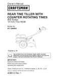
La Figura 20 muestra la orilladora completamente ensamblada.
Cuando se indica el lade izquierdo o derecho de la orilladora en este manual, siempre
se hace desde el punto de vista del operador
en su posici6n detr_s de la unidad.
PAPA SACAR
DE SU CAJA
1.
Saque la botella de aceite y la bolsa de
piezaslpartes de la caja.
2.
Corte hacia abajo las cuatro esquinas de
la caja.
3.
Retire el material de empaque colocado
alrededor de la unidad.
4.
Levante la orilladora de la caja y col&
quela sobre una superficie plana y estable.
Figura 20
F-O21102L
44
ENSAMBLAJE
C6MO LEVANTAR EL MANGO
1.
2.
3.
Afloje las perillas y levante el mango
superior a la posici6n vertical. Ver la
Figura 21. Deje que la vara de control
cuelgue libremente.
Apriete las perillas. Asegt_re que las
perillas queden por el lado de afuera de
los mangos, como se muestra en la
Figura 21.
Inserte el extremo de la vara de control
de izquierda a derecha a trav_s del agujero en en brazo hueco de soporte. Sujete con la horquilla que viene en la
bolsa de partes. Ver la Figura 22.
4.
Cuando la palanca del embrague est6
en la posici6n NEUTRO, el brazo hueco
de soporte debe quedar junto al tornillo
como se muestra en la Figura 23.
Brazo hueco
de so
Vara de
control
Mango
superior
Figura 21
Horquilla
Figura 23
Vara de
control
Brazo hueco
de soporte
Figura 22
F-021102L
45
ENSAMBLAJE
PREPARACI6N
DEL MOTOR
1. Coloque la orilladora sobre una superficie
plana
Cbmo Ilenar el c&rter de aceite
Esta orilladora fue enviada con una botella
de aceite de motor SAE30. Coloque este
aceite en el motor antes de hacer funcionar
la unidad. Para Ilenar el c_rter de aceite, quite la tapa I varilla indicadora de aceite y aSada el aceite de motor SAE30. NO LO
LLENE DEMASIADO.
2. Saque la varilla indicadora (Figura 24).
3. Llene lentamente el c_rter del motor. NO
LO LLENE DEMASIADO.
Cbmo
NOTA: Es posible que el motor ya tenga
un poco de aceite, Durante el proceso de
Ilenado del aceite, compruebe frecuentemente el nivel usando la varilla indicadora, NO LO LLENE DEMASIADO.
Recomendaciones
recipiente de seguridad para el
DVERTENCIA: Use siempre un
combustible, No fume cuando
estd reabasteciendo
el motor. No reabastezca dentro de un local cerrado.
_
La selecci6n del grado de viscosidad SAE
del aceite se hace segt_n la temperatura anticipada de funcionamiento. Aunque los aceites multiviscosidad (5W30, 10W30, etc.)
mejoran el arranque en temperaturas bajas,
su uso en temperaturas por encima de los
40°F (0°C) aumenta el consumo de aceite.
Compruebe el nivel de aceite con mayor fiecuencia para evitar un posible daSo al motor
por operar la unidad con poco aceite.
Apague el motor antes de ahadir combustible, Deje enfriar el motor por varios
minutos.
NOTA: LOS MOTORES QUE HAN SIDO
CERTIFICADOS
PARA CUMPLIR CON
LOS REGLAMENTOS
DE EMISIONES DE
LA EPA (EE,UU,) Y DEL ESTADO DE CALIFORNIA PARA MOTORES ULGE, pueden usar gasolina regular sin plomo.
0°C (32°F)
M_s caliente
_>
__
"
5W30
Cbmo
Ilenar
Estos reglamentos
incluyen los siguientes sistemas de control de emisiones:
EM, TWC (catalizador de triple accibn, si
est_ instalado). Tambi_n incluye cualquier accesorio ajustable por el usuario por Io tanto, no es necesario ning_n otro
SAE30
el c&rter
del motor
con
aceit._e ....
[
de combustible
1. Quite la tapa del tanque de combustible.
para el aceite
_.
4_
"
el tanque
de que el recipiente de gasolina
y sin residuos o contaminantes.
gasolina vieja que haya sido alpor periodos de tiempo prolonga-
2. Llene el tanque de combustible con gasolina de autom6vil limpia, nueva y sin
plomo.
Use s61o aceite detergente de alta calidad
con una clasificaci6n de servicio API de SG.
M_s frio
Ilenar
Asegt_rese
est_ limpio
Nunca use
macenada
dos.
ajuste_
_
Tapa de
ombustible
/
_4_-I_
/
Tapalvarilla
-
F-021102L
__
" indic adora de /_
aceite
\
46
_
'
",,_//
N!VELDE ",o" Figura 24
ACEITE
ENSAMBLAJE
_" LISTA DE COMPROBACION
Para obtener un rendimiento 6ptimo y la mayor satisfacci6n de este producto de alta calidad, favor de revisar la siguiente lista de
comprobaci6n antes de hacer funcionar su
orilladora:
_"
Verifique que se han completado todas las instrucciones de montaje.
_'
Revise la caja de envio para asegurar
que no quede en _sta ninguna pieza
o parte.
_'
Aseg_rese de que todos los sujetadores (pernos, tornillos, etc.) est6n bien
apretados.
A medida que vaya aprendiendo sobre el
uso de la orilladora, preste especial atenci6n
a los siguientes puntos importantes:
_'_'
El nivel de aceite del motor es el correcto.
_'_'
El tanque de combustible ha sido Ilenado con gasolina regular limpia, nueva y sin plomo.
_'_'
FamUiaricese y entienda la funci6n de
todos los controles. Antes de hacer
arrancar el motor, verifique el funcionamiento de todos los controles.
IMPORTANTE: Esta unidad estd equipada con un motor de combustibn interna y no
debe ser usada en o cerca de ning_n terreno basto de cubierta forestal, de maleza o de
hierba a menos que el sistema de escape del motor estd equipado con un parachispas
que cumpla con las leyes locales o estatales aplicables (si existen), Si se usa el
parachispas, el operador debe mantenerlo en buenas condiciones.
Lo indicado anteriormente es requerido pot ley (Section 4442 of the California Public
Resources Code) en el estado de California. Otros estados pueden tener leyes similares, Las leyes Federales aplican a los terrenos federales, Para conseguir un parachispaslsilenciador vaya a su Centro de Servicio Sears mds cercano (consulte la seccibn de
PIEZAS DE REPUESTO en este manual).
NOTA: Es probable que el valor actual constante para los caballos de fuerza sea menor
debido a limitaciones de funcionamiento y a factores ambientales.
F-021102L
47
OPERACION
CONOZCA SU ORILLADORA
ANTES DE HACER FUNCIONAR LA ORILLADORA, LEA EL MANUAL DEL USUARIO Y TODA LA INFORMACION SOBRE SEGURIDAD. Para famUiarizarse con la ubicaci6n de los controles, compare las siguientes
refereneias futuras.
ilustraciones
con su orilladora. Guarde
eete manual
para
MOTOR
Palanca de
embrague
I
Control del acelerador
Vara de
J
control
Control del estrangulador
Cubierta protectora
de la cuchilla
Manija de
VISTA DE LA CUCHILLA
iiiii_i_ii
manual
Cuchilla
Rueda trasera ajustable
Rueda delantera ajustable
Figura 25
Control del acelerador
(si estb equipado) - Controla la velocidad del motor.
se hacia abajo para los bordillos.
Manija de arranque
manual - El motor
esta equipado con una manija de arranque
manual de f_cil uso.
Palanca
de embrague
- Se usa para
hacer arrancar y parar la cuchilla y tambi_n,
para controlar la profundidad de coke.
Cubierta
protectora
de la cuchilla Protege al usuario contra objetos (piedras,
etc.) que pueden ser lanzados por la unidad.
Palanca
de reglaje - Permite ajustar la
unidad de la posici6n de orilladora (vertical)
a la posici6n de recortadora (horizontal). Para cambiar la posici6n, jale la palanca y gire
el brazo hueco de apoyo al _ngulo o posici6n deseada.
Rueda trasera
ajustable
- La rueda
trasera derecha se puede ajustar para nivelar la orilladora cuando se usa para recortar
a Io largo de los bordillos.
Rueda delantera
ajustable
- La rueda
delantera se ajusta de un lado a otro para
equilibrar la unidad. Tambi6n puede ajustar-
PROTECCI6N
PARA LOS OJOS
orilladora
lance objetos
haciala
ADVERTENCIA:
Puede que
los ojos, Io cual puede resultar
en lesiones graves. Use siempre galas
de seguridad o caretas protectoras durante la operacibn de la orilladora.
Use siempre galas o anteojos de seguridad.
Si ya usa anteojos, p6ngase una careta protectora encima de estos.
F-021102L
Palanca de
reglaje
48
OPERACION
C6MO DETENER LA
ORILLADORA
Palanca de
embrague
Mueva la palanca de embrague hacia
atr_s hasta la posici6n DESENGANCHADA. Luego, mueva el control del
acelerador a la posici6n de IDLE o
SLOW, si es posible. Ver la Figura 26.
ORILLADORA
desatendida
DVERTENCIA:
Nunca deje la
mientras el motor estd en mar-
_
cha. Siempre desenganche
pare el motor.
Figura 26
la cuchilla y
I
C6MO USAR EL CONTROL
DEL ACELERADOR
1.
Durante periodos de uso normal, opere
el motor a toda velocidad.
2.
Mueva el control del acelerador hacia
arriba para incrementar la velocidad del
motor, o hacia abajo para aminorarla
(ver la Figura 27).
Control
del acelerador
trangulador
Figura 27
COMO USAR LA PALANCA DEL EMBRAGUE
1.
Arranque
2.
Para enganchar la cuchilla, mueva la
palanca del embrague hacia adelante
(ver la Figura 28).
el motor.
3.
Seleccione la profundidad de corte que
desea. Puede seleccionar entre cinco
opciones, la m_s baja siendo de aproximadamente 7 cm (2-3/4 pulgadas) de
profundidad.
Palanca de
embrague
NOTE: Para un bordeado m_s profundo,
haga el primer corte a poca profundidad,
Luego haga cortes m_s profundos
basra
Iograr la profundidad
deseada,
F-021102L
Figura 28
49
OPERACION
COMO USAR LA PALANCA DE REGLAJE
1,
Apague el motor y desconecte
de la bujia,
el cable
2,
Afloje la perilla de la rueda delantera
que se muestra en la Figura 29, Deslice
completamente la rueda delantera hacia el lado derecho,
3,
Apriete bien la perilla
lantera.
de la rueda de-
NOTA: Para evitar que la cuchilla de
la orilladora golpee contra la rueda
mientras recorta, aseg_rese de que la
rueda delantera est_ ubicada en el extremo derecho.
4,
Perilla de la
rueda delantera
Desenganche la palanca de reglaje
(ver la Figura 30), Mueva la palanca de
reglaje hasta la ranura marcada 90 ° ,
5.
Reconecte
6.
Arranque
7,
Mueva la palanca de embrague hasta
Iograr la altura de recorte deseada,
Rueda
delantera
Figura 29
el cable de la bujia.
el motor,
i
orilladora desatendida con el
DVERTENCIA:
Nunca deje la
motor en marcha, Siempre desenganche la cuchilla de recorte y apague el motor antes de ajustar las ruedas
o cambiar la posicibn de la cuchilla de
recorte,
_
F-021102L
Palanca de reglaje
50
Figura 30
OPERACION
C6MO USAR LA FUNCIONALIDAD
DE ABORDILLADO
Baje la rueda delantera hasta que _sta
se encuentre al mismo nivel que la rueda trasera izquierda y la orilladora quede
situada en el bordillo como se muestra
en la Figura 31.
Dado que se pueden ajustar la rueda delantera y la rueda trasera derecha, la orilladora
puede usarse en superficies desniveladas,
tales como el bordillo mostrado en la
Figura 31. Para ajustar la posici6n de las
ruedas, siga los pasos a continuaci6n:
1.
7.
Afloje la perilla de la rueda trasera.
8.
Baje la rueda trasera derecha hasta
que la orilladora se encuentre nivelada y
la rueda trasera izquierda quede sobre
el bordillo,
9.
Apriete bien la perilla de la rueda trase-
Apague el motor.
2.
Desconecte
el cable de la bujia.
3.
Afloje la perilla de la rueda delantera.
4.
Deslice la rueda delantera para que pase sin rozar el bordillo y equilibrar la unidad.
5.
Apriete bien la perilla de la rueda delantera.
6.
Use la palanca de ajuste de altura del
bordillo para bajar la rueda delantera.
l'a,
10. Conecte el cable de la bujia.
_
alejado
de la cuchilla
giratoria
DVERTENCIA:
Mantdngase
para evitar posibles lesiones.
CubieAa protectora
de la cuchilla
Perilla de
la rueda
delantera
Eje de soporte
Perilla de la
rueda trasera
.....
Rueda delantera
Rueda trasera
derecha
Figura 31
F-021102L
51
OPERACION
COMO PARAR EL MOTOR
1. Para apagar el motor, suelte la palanca de
parada del motor.
2. Si el motor continea encendido, mueva la
palanca de control del acelerador hacia
la posici6n de PARADA (STOP).
C6MO ARRANCAR
8. Sujete firmemente el mango de la orilladora con su mano izquierda.
9. Jale r_pidamente la manija de arranque
manual. EVITE que la cuerda de arranque
se enrolle de un golpe. Haga que la cuerda se enrolle lentamente. Si el motor no
arranca despu6s de tres intentos, oprima
el bot6n cebador dos veces y jale nuevamente la manija de arranque manual.
EL MOTOR
ADVERTENCIA:
Cuando el motor estd en marcha, la cuchilla
girando. Para prevenir
lesiones, mantenga las manos y los
pies alejados de la cuchilla.
IMPORTANTE: Antes de arrancar el motor,
Ileve la orilladora al drea donde la usar&
Examine los controles varias veces. Aseg_rese de que estos se mueven libremen-
de acelerador
Control de
acelerador
te,
1. Revise el nivel del aceite.
2. Llene el tanque de combustible con gasolina regular sin plomo. La gasolina debe
ser limpia. El uso de gasolina con plomo
aumentar_ la acumulaci6n de dep6sitos y
reducir_ la vida _til de las v_lvulas.
Control
Figura 32
10.AI arrancar el motor, mueva la palanca de
control del acelerador a la posici6n de
marcha r_pida (FAST). Mantenga esta
posici6n durante el uso normal de la unidad.
NOTA: No use gasohol ni metanol. Tampoco use gasolina s_per sin plomo.
_
recipiente de seguridad para el
DVERTENCIA: Use siempre un
i combustible, No fume cuando
11. Si el motor no arranca despu_s de 5 6 6
intentos, consulte las instrucciones de la
"Tabla de Iocalizaci6n de averias".
estd reabasteciendo el tanque de combustible, No reabastezca dentro de un
local cerrado, Apague el motor antes de
Ilenar el tanque de combustible y deje
enfriar el motor por varios minutos.
NOTA: La velocidad del motor controla la
velocidad de la cuchilla giratoria, Para reducir la velocidad de la cuchilla giratoria,
reduzca la velocidad del motor. Para aumentar la velocidad de la cuchilla giratoria,
aumente la velocidad del motor.
3. Asegt_rese de que el cable de la bujia est_
conectado a _sta.
4. Jale la palanca de parada del motor completamente hacia atr_s hasta la posici6n
ENGANCHADO. Sujete la palanca de parada del motor contra el mango.
que
el motor en un
localarrancerraADVERTENCIA:
Nunca
do o sin ventilacibn. El motor
genera emisiones de monbxido de carbono, un gas inodoro y potencialmente
fatal. Mantenga las manos, los pies, el
cabello y la ropa holgada alejados de
las piezas en movimiento. Evite el contacto con el silenciador y los componentes que Io rodean, la temperatura de
dstos puede exceder los 66°C (150°F).
_
5. Ponga la palanca de control del aceleradot (si est_ equipado) en la posici6n de
marcha r_pida (FAST) (Figura 32).
6. Mueva el control del estrangulador
hacia la posici6n CHOKE (Figura 32).
7. Para arrancar el motor, agarre firmemente
la manija de arranque manual con su mano derecha.
F-021102L
del estrangulador
52
OPERACION
RECOMENDACIONES PARA EL
USO DE SU ORILLADORA
• La orilladora trabaja mejor cuando el tiempo est_ seco. Si la tierra est_ muy mojada, el barro se pega y acumula alrededor
de la cuchilla haciendo que _sta se desgaste prematuramente y que la unidad no
funcione como debe.
• Si se pega el barro a la cuchilla, apague el
motor y desconecte el cable de la bujia.
Quite el barro y basura pegados a la cuchilla.
• Para un bordeado m_s profundo, corte
primero a poca profundidad. Luego, haga
cortes m_s profundos hasta Iograr la profundidad deseada.
• Para obtener un borde parejo, asegt_rese
de que la guia de la cuchilla se deslice
sobre la superficie del suelo.
• El bordeado puede modificarse variando
el nt_mero de pasadas y tambi6n por la
distancia en que se encuentre la cuchilla
en relaci6n a la superficie.
del usuario, Familiarfcese con
ADVERTENCIA:
Lea el Manual
la ubicacibn y la funcibn de
todos los controles, Mantenga todos los
dispositivos de seguridad y protectores
en su lugar. Nunca permita que usen la
unidad los nihos o adultos no familiarizados con la orilladora, Apague el motor antes de limpiar la cuchilla o de hacer reparaciones a la unidad. Mantenga
a los espectadores o transe_ntes a una
buena distancia de la mdquina, Mantenga alejadas de la cuchilla todas las partes giratorias que puedan causar lesiones.
F-O21102L
53
MANTENIMIENTO
RESPONSABILIDADES
DEL USUARIO
REGISTRODESERVICIO
Anotelasfechasa medida que completecada
servicio,
Lubricar la varilla/tubo
FECHAS
DE
SERVICl0
hue-
CO
ESPEClFICACIONES
PRODUCTO
Modelo No.:
DEL
RECOMENDACIONES
GENERALES
La garantia de esta Orilladora no cubre piezas que hayan sido sometidas a abuso o
negligencia por parte del usuario. Para obteher el valor total de la garantia, el usuario
debe mantener la orilladora de acuerdo alas
instrucciones de este manual.
536.772340
Fecha de compra:
Caballos de fuerza:
4
Desplazamiento:
9.02 pulg. cu.
(148 cc.)
Capacidad
Entrehierro:
F-021102L
Para mantener su orilladora en buen estado,
es necesario hacerle algunos ajustes peri6dicamente.
de aceite: 21 onzas SAE-30W
0,030 pulgada
Todos los ajustes que aparecen en la secci6n de Servicio y Ajustes de este manual
deben ser revisados por Io menos una vez
en cada estaci6n.
54
MANTENIMIENTO
LUBRICACI6N
4.
Quite la tapa del aceite (ver la
Figura 33). Llene lentamente el c_rter de
motor. No Io Ilene demasiado. Consulte
las "Especificaciones del producto" para
obtener informaci6n sobre la cantidad y
grado de aceite. Ponga nuevamente la
tapa del aceite.
5.
Conecte el cable de la bujia.
Despu6s de cada 25 horas de uso, aplique
unas gotas de aceite de motor a todas las
piezas movibles, especialmente a las ruedas.
Cbmo
cambiar
el aceite
de motor
Gamble el aceite en el c_rter del motor despu6s de cada 25 horas de uso.
Tapa del aceite
NOTA: El aceite se vacia con mayor facilidad cuando el motor est_ caliente.
1.
Desconecte
2.
Quite el tapbn de drenaje de aceite.
Vacie el aceite dentro de un recipiente
piano.
el cable de la bujia.
3.
Una vez drenado el aceite, instale y
apriete el tapbn de drenaje de aceite.
naje de aceite
Figura 33
C()M0 CAMBIARELFILTR0 DEAIRE
PRECAUCI6N:
Nunca opere la unidad sin
un filtro de aire. Un filtro dahado reducird
el rendimiento del motor. Si entra polvo u
otto contaminante en el motor a travds
del carburador, el motor se desgastard
excesivamente o se dahar& Debe reemplazar inmediatamente el filtro de aire si
dste se encuentra dahado u obstruido.
Bajo condiciones de uso normales, reemplace el filtro de aire una vez al aSo, pero con
mayor frecuencia en condiciones polvorientas o sucias. Cambie el filtro de aire, si est_
equipado, yio el cartucho si est_ muy sucio o
daSado.
1.
Desconecte
2.
Afloje los tornillos o remueva la tapa.
(Ver la Figura 34.)
3.
Remueva el pre-filtro, si est_ equipado,
y el cartucho cuidadosamente
para prevenir que caigan desechos dentro del
carburador.
4.
el cable de la bujia.
TI nill°
Para darle servicio al pre-filtro, I_velo
en detergente liquido y agua. Esc_rralo
hasta secarlo en un trapo limpio. Satt_reIo en aceite para motor. Esc_rralo con
un trapo absorbente para remover TODO EL EXCESO de aceite.
PRECAUCION:
pa
Pre-filtro
Para darle servicio al car-
tucho, limpielo golpedndolo ligeramente
sobre una superficie plana. No use solventes a base de petrbleo, tal como, kerosene, el cual ocasionard que se deteriore
el cartucho. No use aire presurizado, ya
que este puede dahar el cartucho. No
aceite el cartucho.
5.
Reinstale el cartucho y el pre-filtro, si est_ equipado.
6.
Coloque la tapa y apriete los tornillos
la perilla firmemente.
7. Conecte el cable de la bujia.
F-021102L
CaAucho
o
Figura 34
55
MANTENIMIENTO
BUJ|A
Revise la bujia cada 25 horas de operaci6n
de la unidad. Debe reemplazar la bujia si los
electrodos se encuentran dafiados o quemados, o si la porcelana est_ fisurada.
jia hasta Iograr un par de torsi6n de 15
libras-pie.
L_mina calibradora
0,030 pulg.
Aseg_rese de que la bujia est_ limpia.
Si no Io est,, raspe cuidadosamente los
electrodos (no use chorros de arena ni
cepillos de alambre).
2.
Revise el entrehierro de la bujia usando
una I&mina calibradora.
3.
Antes de instalar la bujia, aplique una
capa ligera de aceite a la parte roscada
para facilitar su remoci6n. Apriete la bu-
AJUSTE
DEL
Bujia
Figura 35
CARBURADOR
Nunca haga ajustes innecesarios al carburador. El carburador ha sido calibrado en la
f_brica para funcionar de manera 6ptima en
la mayoria de las condiciones de uso. No
obstante, si es necesario ajustarlo, se recomienda comunicarse con el Centro de servicio de Sears m_s cercano a usted.
velocidad del motor ha sido caADVERTENCIA:
El regulador dc
librado en la fdbrica, No haga
ajustes al regulador de velocidad, Hacer
funcionar el motor a una velocidad excesiva puede ser peligroso. Si piensa que
el regulador de velocidad del motor requiere un ajuste, comuniquese con el
Centro de servicio de Sears mds cercanc
a usted.
F-021102L
56
SERVICIO
C6MO DESMONTAR
Y AJUSTES
LA CORREA
La correa est_ hecha de un material especial. Si la correa se desgasta o se rompe,
reempl_cela con un repuesto original,
1.
Desconecte
2.
Jale la palanca de embrague hacia atr_s
para soltar la tensi6n de la correa.
3.
4.
el cable de la bujia.
5.
Afloje, pero no quite, el tornillo que sujeta la guia de la correa. Separe la
guia de la correa de la correa.
Quite los dos tornillos de la cubierta
protectora de la correa (ver la
Figura 37).
Quite los dos tornillos y los separadores de la parte superior de la cubierta
de la polea motriz. Retire la cubierta
de la polea motriz (ver la Figura 36).
6.
Quite la correa vieja de las poleas motriz y del conjunto del brazo hueco,
Reempl_cela con un repuesto original.
7.
Para instalar la correa nueva, siga los
pasos anteriores en orden inverso.
Separador
Cubierta protectora
de la correa
Figura 37
TorniNos
F-021102L
Figura 36
57
SERVICIO
C6MO REEMPLAZAR
Y AJUSTES
LA CUCHILLA
La cuchilla est_ sujeta a desgaste y da_os,
tales como hendeduras y abolladuras. Generalmente _stas no afectan el funcionamiento
de la unidad.
La cuchilla est_ diseSada de manera que no
necesite ser afilada. No intente afilarla. Adem_s, la cuchilla es reversible. Si _sta tiene
muchas hendeduras o abolladuras, saque la
cuchilla e invi_rtala (dela vuelta). De esta
manera tendr_ un buen filo para cortar.
Reemplace la cuchilla si ambos lados est_n
gastados o daSados.
Desconecte
el cable de la bujia.
2,
Retire la contratuerca de cuchilla que
sujeta la cuchilla al eje motor.
apretar
la contratuerca
de la o
ADVERTENCIA:
Para sacar
cuchilla, use siempre el re@todo ilustrado en la Figura 38. Coloque
siempre una Ilave de boca para sujetar
el perno ubicado detr&s de la cuchilla,
cuchilla, El afilado puede daADVERTENCIA:
No afile la
hat la cuchilla y hacer que _sta se rompa, Io cual puede causar lesiones a usted u otras personas.
Para reemplazar
a continuaci6n.
1.
3.
Retire la cuchilla.
4.
Instale una cuchilla y una contratuerca
nueva. Apriete la contratuerca a un par
de torsi6n de 40 a 45 libras-pie.
5.
Conecte el cable de la bujia.
la cuchilla, sigas los pasos
Gire la Ilave para apretar la contratuerca
i:ii:iiiiii ii:i!!!!iiiiiiiii
Inmovilice la tuerca, no la gire
Contratuerca
de la cuchilla
Figura 38
F-021102L
58
SERVICIO
Y AJUSTES
ALMACENAMIENTO
la orilladora con combustible
ADVERTENCIA:
Nunca guarde
en el tanque en un recinto cerrado. Nunca la guarde en un &tea cerrada y con poca ventilacibn, donde los vapores del combustible pudieran alcanzar
una llama expuesta, chispas o el piloto
en un sistema de calefaccibn, calentador
de agua o secadora de ropa.
gasolina del tanque
ADVERTENCIA:
No mientras
saque la
se encuentra dentro de un recinto cerrado, cerca de un incendio o
una llama expuesta, o mientras est_ fumando. Los vapores de la gasolina pueden causar una explosibn o un incendio.
Cuando es necesario almacenar la orilladora
por treinta dias o m_s, siga los pasos indicados a continuaci6n para asegurar que la oriIladora est6 en buenas condiciones de uso
ponentes del sistema de combustible, tales como el carburador, filtro del
combustible, linea del combustible y tanque, durante el almacenamiento de la unidad. Adem_s, el uso de combustibles
mezclados con alcohol (llamados gasohol, etanol o metanol) puede atraer humedad Io cual Ileva a la separacibn del
combustible y a la formacibn de _cidos
durante el almacenamiento de la unidad.
Los gases _cidos pueden dahar el sistema de combustible de un motor mientras
la unidad est_ guardada,
Para prevenir el daSo al motor cuando la oriIladora est_ guardada por 30 dias o m_s,
siga los pasos siguientes:
•
Deje el motor andando hasta que se le
termine la gasolina.
•
Si usted no desea sacar la gasolina del
tanque, aSada a _sta un estabilizador de
combustible a la gasolina que queda en
el tanque. El estabilizador de combustible minimizar_ los dep6sitos de resina y
los _cidos. Si el tanque de combustible
est_ casi vacio, mezcle el estabiUzador
para la siguiente estaci6n.
Orilladora
•
Limpie bien la orilladora.
•
Revise la orilladora por si tuviera partes
o piezas gastadas o daSadas. Apriete
todas las partes que est6n sueltas.
•
Coloque una pequeSa cantidad de aceite de motor a todas las partes movibles,
especialmente alas ruedas.
•
Guarde la orilladora en un recinto que
tenga buena ventilaci6n.
•
Cubra la orilladora con una cubierta
apropiada que no retenga humedad. No
use pl_stico.
con gasolina fresca en otro recipiente y
aSada la mezcla al tanque de combustible. Siga siempre las instrucciones que
aparecen en el envase del estabilizador.
Arranque el motor. Deje que el motor corra por 10 minutos para permitir que la
mezcla alcance el carburador.
•
Cambie el aceite del motor. Consulte
"C6mo cambiar el aceite del motor" en la
secci6n de Mantenimiento.
•
Lubrique el _rea del pist6niciUndro. Esto
se puede hacer quitando primero la bujia
y colocando una pequeSa cantidad de
aceite de motor limpio en el orificio de la
bujia. Luego, cubra el orificio de la bujia
con un paso para absorber el aceite rociado. A continuaci6n, haga girar el motor jalando la manila de arranque manual
dos o tres veces. Por _ltimo, instale la
bujia y conecte el cable de la misma.
•
Almacene la orilladora en la posici6n de
operaci6n con las ruedas sobre el suelo.
Si almacena la orilladora en cualquier
otra posici6n, el aceite del c_rter del motor entrar_ en el ciUndro Io cual causaria
IMPORTANTE: Nunca cubra la orilladora
mientras el motor y las _reas de escape
est_n todavia calientes.
NOTA: Una revisibn o un afinamiento
anual hecho en un Centro de servicio de
Sears es una buena manera de asegurar
que su orilladora le brindar& un bptimo
rendimiento en la prbxima estacibn
Motor
IMPORTANTE: Es importante evitar que
se formen residuos de resina en los com59
F-021102L
un problema de servicio.
TABLA DE LOCALIZACION
PROBLEMA
CAUSA
El motor no arranca o
arranca con dificultad
Combustible
El motor marcha de forma
irregular
El motor no cone a toda
marcha
El motor genera humo
excesivo
La cuchilla no gira
La cuchilla no corta de la
manera correcta
Vibracibn
excesiva
El motor no se apaga al
soltar la palanca de parada
del motor
F-021102L
DE AVERIAS
SOLUCI6N
viejo
Vacie el tanque de
combustible. LI6nelo con
combustible fresco.
Filtro de combustible
obstruido
Reemplace el filtro de
combustible.
Suciedad en el tanque de
combustible o falta de
combustible
Limpie el tanque de
combustible.
Carburador
Lleve la unidad a un Centro
de servicio de Sears.
desajustado
Bujia sucia
Limpie y calibre el
entrehierro de la bujia.
Filtro de aire sucio
Reemplace
el filtro de aire.
Filtro de aire obstruido
Reemplace
el filtro de aire.
Barro alrededor de la cuchilla
Limpie el barro de la cuchilla.
Cuchilla suelta
Apriete la tuerca de la
cuchilla.
Correa en "V" daSada
Reemplace
Cojinetes daSados en el
conjunto de brazo hueco
Reemplace el conjunto de
brazo hueco,
Cuchilla daSada o gastada
Invierta o reemplace la
cuchilla.
Piezas / partes sueltas
Apague el motor
inmediatamente. Apriete
todos los sujetadores. Si la
vibraci6n persiste, Ileve la
unidad a un Centro de
servicio de Sears.
Mango suelto
Apriete las perillas del
mango,
60
la correa en "V".
SEARS,
ROEBUCK
AND CO.
Garantia limitada de cumplimiento con el Sistema Federal
de control de emisiones y con el sistema de control de
emisiones del Estado de California
Motores pequefios no aptos para carretera (off-road)
CONTROL DE EMISIONES DE
CALIFORNIA Y DE LA AGENCIA DE
PROTECCION AMBIENTAL (EPA) DE
E.U.A. - DECLARACI_)N DE LA
GARANT|A
SISTEMA PARA EL CONTROL DE
EMISIONES DEL FABRICANTE COBERTURA DE LA GARANT|A
Los sistemas para el control de emisiones modelo 1995 y modelos de aSos posteriores de
motores pequeSos para vehiculos off-road en
California est_n garantizados por dos afios, tal
y como se menciona en la presente garantia.
En otros estados, los motores modelo 1997 y
modelos de afios posteriores tambi6n est_n
garantizados por dos afios. En caso de que,
durante dicho periodo de la garantia, cualquier
parte de su motor relacionada con emisiones
est6 defectuosa en sus materiales o hechura,
Sears, Roebuck and Co. reparar_ o cambiar_
dicha parte.
La Agencia de Protecci6n Ambiental de los
Estados Unidos (en Io sucesivo "EPA"), el
Consejo de California para los Recursos del
Aire (en Io sucesivo "CARB") y Sears, Roebuck and Co. tienen el placer de explicar Io que
es la Garantia Federal y de California para Sistemas de Control de Emisiones de su nuevo
motor pequefio para vehiculos off-road. En
California, los motores pequefios para vehiculos off-road de modelo 1995 y modelos de
afios posteriores deben ser diseSados, construidos y equipados para cumplir con las estrictas normas anti contaminaci6n del Estado.
En otros estados, los motores modelo 1997 y
modelos de aSos posteriores deben estar diseSados, construidos y equipados, al momento de su venta, para que cumplan con las
disposiciones de la EPA acerca de motores
pequefios para vehiculos off-road. Sears,
Roebuck and Co. garantizar_ el sistema para
el control de emisiones de su motor pequeSo
para vehiculos off-road por los periodos de
tiempo que se mencionan m_s adelante, con
tal que su motor pequeSo para vehiculos offroad no haya sufrido algt_n abuso, negligencia,
modificaci6n
no
aprobada
o
mantenimiento indebido.
RESPONSABILIDADES
DEL
PROPIETARIO DE LA GARANT|A
Como propietario del motor pequeSo para vehiculos off-road usted es responsable de que
se Ileve a cabo el mantenimiento requerido
que se menciona en el Manual del Propietario,
pero Sears, Roebuck and Co. no negar_ la garantia _nicamente debido a la falta de un reciboo a que usted no proporcione una prueba
escrita de que se ha Ilevado a cabo el mantenimiento programado.
No obstante, usted, como propietario del motor pequeSo para vehiculos off-road, deber_
estar consciente de que Sears, Roebuck and
Co. le puede negar la cobertura de la garantia
si su motor o alguna parte del mismo ha fallado
debido a un abuso, negligencia, mantenimiento inadecuado o modificaciones no aprobadas.
Es probable que su sistema para el control de
emisiones incluya partes como el carburador,
el sistema de encendido y el sistema de escape. Tambi_n es posible que se incluya el sistema de descompresi6n
y otros ensamblajes
relacionados con emisiones.
Usted es responsable de presentar su motor
pequefio para vehiculos off-road en el Taller
Autorizado de Servicio de Sears, Roebuck
and Co. en cuanto surja el problema. Las reparaciones bajo la garantia deben Ilevarse a cabo dentro de un periodo de tiempo razonable
que no exceda de 30 dias.
Cuando surja una condici6n protegida por la
garantia, Sears, Roebuck and Co. reparar_ su
motor pequeSo para vehiculos off-road sin
costo alguno para usted por concepto de diagn6stico, partes y mano de obra.
F-021102L
Se puede programar el servicio de garantia
Ilamando al Taller Autorizado de Servicio de
61
Sears, Roebuck and Co. o a Sears, Roebuck
and Co. al 1-800-473-7247
(llamada gratuita
en E.U.A.).
NOTA IMPORTANTE
Esta declaraci6n de la garantia explica los derechos y las obligaciones que usted tiene de
conformidad con la Garantia del Sistema para
el Control de Emisiones (en Io sucesivo la "Garantia SCE"), la cual Sears, Roebuck and Co.
le proporciona de conformidad con las leyes
de California. V_ase tambi6n las Garantias Limitadas de Sears, Roebuck and Co. que se
adjuntan a la Garantia SCE en una hoja por
separado y que tambi6n le proporciona Sears,
Roebuck and Co. La Garantia SCE _nicamente se aplica en el sistema para el control de
emisiones de su motor nuevo. Hasta el punto
en donde no haya ningt_n conflicto en t6rminos
entre la Garantia SCE y la Garantia de Sears,
Roebuck and Co., la Garantia SCE aplicar_
para cualquier circunstancia a excepci6n de
aqu611a en que la Garantia de Sears, Roebuck
and Co. pueda proporcionar un periodo de garantia m_s largo. La Garantia SCE y la Garantia de Sears, Roebuck and Co. describen
importantes derechos y obligaciones que usted tiene con respecto a su motor nuevo.
$61o se puede Ilevar a cabo el servicio de garantia en un Taller Autorizado de Servicio de
Sears, Roebuck and Co. AI momento de solicitar un servicio de garantia, se debe presentar
una prueba de la fecha de compra por parte
del comprador original. El comprador pagar_
cualquier cargo por concepto de Ilamadas de
servicio yio transportaci6n de productos desde y para el lugar en donde se Ileve a cabo el
trabajo de inspecci6n yio garantia. El comprador ser_ responsable de cualquier daSo o p6rdida en el que se incurra con relaci6n a la
transportaci6n de cualquier motor o cualquier
parte del mismo que se presente para inspecci6n yio trabajo de garantia.
Si tiene alguna pregunta con relaci6n a sus derechos y responsabiUdades, deber_ Ilamar a
Sears, Roebuck and Co. al 1-800-473-7247.
GARANT|A DEL SISTEMA PARA EL
CONTROL DE EMISIONES
Garantia del Sistema para el Control de Emisiones ("Garantia SCE") de motores peque5os para vehiculos off-road modelo 1995 y
modelos de aSos posteriores en California
(para otros estados, motores modelo 1997 y
aRos posteriores):
62
F-021102L
A. CAMPO DE APLICACI6N:
Esta garantia
deber_ aplicarse a los motores pequeSos para
vehiculos off-road modelo 1995 y modelos de
aSos posteriores en California (para otros estados, motores modelo 1997 y modelos de
aSos posteriores). El Periodo de la Garantia
SCE iniciar_ en la fecha de entrega del nuevo
motor o equipo al comprador original y continuar_ durante los siguientes 24 meses consecutivos.
B, COBERTURA
GENERAL DE LA GARANT|A DEL SISTEMA PARA EL CONTROL DE EMISIONES: Sears, Roebuck and
Co. garantiza al comprador original del nuevo
motor o equipo y a cada comprador subsecuente que su motor pequeSo para vehiculos
off-road est.:
1. DiseSado, construido y equipado para que
cumpla con todas las disposiciones aplicables
adoptadas por el Consejo para los Recursos
del Aire de conformidad con su autoridad especificada en los Capitulos 1 y 2, Parte 5, Divisi6n 26 del C6digo de Salud y Seguridad, y
2. Libre de defectos en sus materiales y mano
de obra, los cuales, en cualquier momento durante el Periodo de la Garantia SCE, cause la
falla de una parte relacionada con emisiones
y que est_ bajo la garantfa en cuanto a que no
sea id_ntica en sus materiales a la parte descrita en la solicitud de motor del fabricante para su certificaci6n.
C. La Garantia SCE s61o ataSe alas partes de
su motor relacionadas con emisiones de la siguiente manera:
1. Cualquier parte relacionada con emisiones
que no se especifique como de cambio, tal y
como se requiere en el mantenimiento especificado en el Manual del Propietario, deber_ garantizarse por el Periodo de la Garantia SCE.
Si dicha parte falla durante el Periodo de la Garantfa SCE, Sears, Roebuck and Co. la reparar_ o cambiar_ de acuerdo con la Subsecci6n
4 que se menciona m_s adelante. Cualquier
parte reparada o cambiada de conformidad
con la Garantia SCE deber_ estar garantizada
por el resto del Periodo de la misma.
2. Cualquier parte garantizada y relacionada
con emisiones que est6 especificada s61o para inspecciones regulares conforme al Manual
del Propietario deber_ estar garantizada por el
Periodo de la Garantia SCE. Una declaraci6n
en dichas instrucciones por escrito a efecto de
"reparar o cambiar tal y como sea necesario"
no reducir_ el Periodo de la Garantia SCE. Dicha parte reparada o cambiada conforme a la
Garantia
SCE
deber_
garantizarse
porelresto aprobada
porSears,
Roebuck
andCo.para
delPeriodo
delamisma.
utilizarse
eneldesempeSo
decualquier
mantenimiento
ocambio
delaGarantia
SCE,
la
3.Cualquier
parlegarantizada
yrelacionadacualseproporcionar_
sin
cargo
alguno
para
el
conemisiones
queseespecifique
para
cam- propietario.
Dicho
uso
noreducir_
las
obligabio,deconformidad
conelManual
delPropie- clones
deSears,
Roebuck
andCo.conforme
tario,deber_
garantizarse
porelperiodo
de alaGarantia
SCE.
tiempo
previo
alprimer
punto
decambio
de
queseagreguen
omodifiquen
esaparle.
Silaparlefallaantes
delprimer 9.Laspartes
nosepodr_n
utilizar
para
mocambio
programado,
Sears,
Roebuck
andCo. sinaprobaci6n
oreparar
unmotor
deSears,
Roebuck
reparar_
ocambiar_
esaparle
deacuerdo
con dificar
usoanula
estaGarantia
SCE
y
laSubsecci6n
4quesemenciona
m_sadelan- andCo.Dicho
lasbases
suficientes
para
rechate.Cualquier
parle
relacionada
conemisionesconformar_
deunaGarantia
SCE.
Sears,
queserepare
ocambie
deconformidad
conla zarlademanda
andCo.noser_responsable,
conGarantia
SCEdeber_
estar
garantizada
porel Roebuck
aestagarantia,
porlasfallas
decualresto
delPeriodo
delamisma
previo
alprimer forme
parle
garantizada
deunmotor
deSears,
punto
decambio
programado
deesaparle
re- quier
lacionada
conemisiones.
Roebuck
andCo.causadas
porelusodedichaparle
agregada
omodificada
sinaproba4.Lareparaci6n
oelcambio
decualquier
parte ci6n.
garantizada
y relacionada
conemisiones
de
conformidad
conestaGarantia
SCEsedebe- LAS PARTES RELACIONADAS
CON
r_Ilevar
acabo,
sincargo
alguno
para
elproEMISIONES
INCLUYEN
A LAS
pietario,
enunTaller
Autorizado
deServicio
de
SIGUlENTES:
Sears,
Roebuck
andCo.
1. Ensamblaje del carburador y sus compo5.Nosecargar_
alpropietario
elcosto
portra- nentes
internos
bajodediagn6stico,
elcualIleva
aladeterminaci6n
dequeunaparleprotegida
porla a) Filtro de combustible
Garantia
SCE
siest_defectuosa,
provisto
que b) Empaques (juntas) del carburador
dicho
trabajo
dediagn6stico
seIleve
acabo
en
unTaller
Autorizado
deServicio
deSears, c) Tubo de entrada
Roebuck
andCo.
2. Ensamblaje del depurador de aire
6.Sears,
Roebuck
andCo.ser_responsablea) Elemento del filtro de aire
dedaSos
aotros
componentes
originales
del
motor
omodificaciones
aprobadas
queproba- 3. Sistema de encendido, que incluye:
blemente
sean
causados
porunafallacom- a) Bujia de encendido
prendida
en la garantia
de unaparle
relacionada
conemisiones
cubierta
porlaGa- b) M6dulo de encendido
rantia
SCE.
c) Ensamblaje del volante
7.Durante
elPeriodo
delaGarantia
SCE, 4. Silenciador catalitico (si est_ equipado)
Sears,
Roebuck
andCo.deber_
conservar
un
suministro
departes
garantizadas
yrelaciona-a) Empaque del silenciador (si est_ equipado)
dasconemisiones
queseasuficiente
para
cumplir
lademanda
esperada
deesas
partes b) Colector de escape (si est_ equipado)
relacionadas
conemisiones.
5. Ensamblaje del respiradero del c_rter del ci8.Sepuede
utiUzar
cualquier
parle
derepues- g0eSal y sus componentes
torelacionada
conemisiones
autorizada
y a) Tubo de conexi6n del respiradero
10/22199 EPNCARB
Sears, Roebuck
F-021102L
and Co., Hoffman
63
Estates, IL 61)179 U.S.A.
For repair of major brand appliances in your own home,..
no matter who made it, no matter who sold it}
(1-800-469-4663)
www_sears,com
To bring in products such as vacuums,
lawn equipment:and e!ect_onics for repairi call for
the location of your nearest Sears Parts & Repair Center,
1-800-488-1222
_y_im_,
,igh_
www, sears.com
For the replacement pa_s, accessories and owner s manuals
that you need to do-it-yourself, call Sears Pa_sDirectS_!
1-800-366-PART
6a.m.-pm
(1-800_366_7278)
CST,
7 days a week
www.sears.com!partsdirect
To purchase or inquire about a Sears Service Agreement:
Para pedir sepaicio de reparaciSn a domicilJo,
y pare erdenar piezas con entrega a domicilio:
1_-SU-H
OGAR s_
_t-888:-784-6427)
@ Sears,
RSeb_c_
a:nd c#,
,_ R_istered
Tra_mark
_'_ Marca
_t_da
R_
. Tidemark
_ _r_ M_rca
d_ FAbrica
_f Sea_
R_ebu_
a_a O_
_. £ea_s_ R_e#Li_k
_r_d CO,

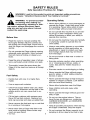

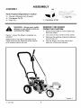
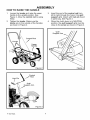
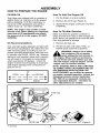
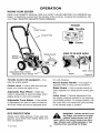
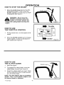
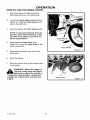

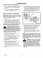

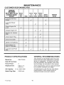
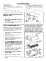
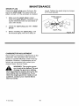
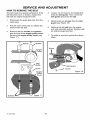
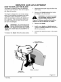
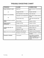
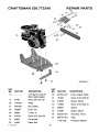
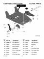
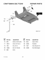
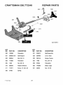

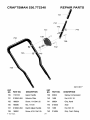
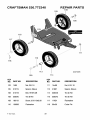


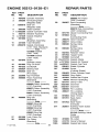
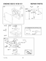
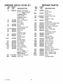
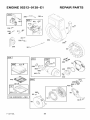
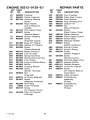
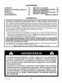

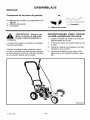

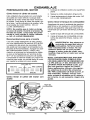


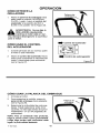
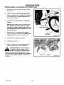
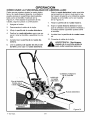
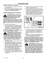
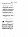
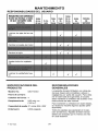
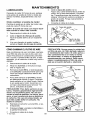


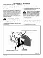
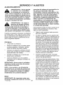
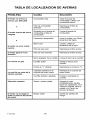


![CRRFTSMRN °] - at snowblowerguide.com](http://vs1.manualzilla.com/store/data/006202620_1-711fb90bb2c79d693479b4ac54c29ad0-150x150.png)