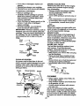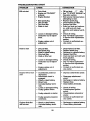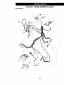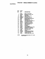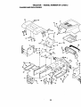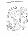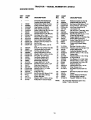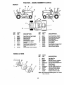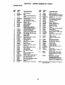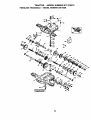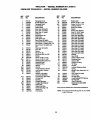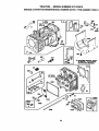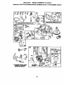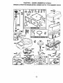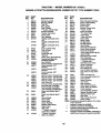
1
Owner's
Manual
[RAFTZMAN +
14.5 HP
ELECTRIC START
42" MOWER
6 SPEED TRANSAXLE
LAWN TRACTOR
Model NO.
917.270512
•
•
•
•
Safety
Assembly
Operation
Maintenance
\
• Repair Parts
CAUTION:
Read and follow all
Safety Rules and Instructions
before operating this equipment.
For answers to your questions
about this product, Call:
1-800-659-5917
Sears Craftsman Help Line
5 am - 5 pm, Mon- Sat
Sears, Roebuck and Co., Hoffman Estates, IL 60179
Maintenance......................................... 17
Service and Adjustments............ ._,..... _.21
S_ificetions
........................... 5
Storage................................................. 27
..........:............................
8 Troubleshooting.................................... 28
__o_.;..._;-...,.i..:;_
..... :..... ,_.............. 11
Repair Parts ......................................... 34
Parts Ordering ....................... Back Cover
Maint_ance_chedule,
...... _,...,............. 17
•.Warranty ............. _;..................................
2
LIMITI_D "1"_O yEAR W'AR_AN_Y ON CRAFTSMAN RIDING EQUIPMENT
For twct (2)_eam irom tl_ d4te oi purchase, if this Craftsman Riding Equipment is maintained,I,_.u.ubrilcat. a _ tu!p'edup_according to the instructions in.the owner's manual,
Sears vtill r_paie_dt
or rr_,
place, frlee o.fcharge, any parts found to be defective in material or
workmanship.
'
....
This W4rrar_ty a_es !_otc[pvel_:
• Expendable items which bc_,co_e worn during normal use, such as blades, spark
• plugs|air [clea_ers, belts,eic.
Tire r_pla_em_nt or redair _aused by punctures from outside objects, such as nails,
thom_, stlJmp_, or glas'_, i
;
• Repa_'s n_ce_ary because of operator abuse, negligence, improper storage or accident dr th_ failbre to m&intaln the equipment according to the instructions contained in
the owner's manual.
• Riding equipment used for commercial or rental purposes.
LIMITED 90 DAY WARRANTY ON BATTERY
For ninety (90) days from date of purchase, if any battery included with this riding equipment proves defective in material or workmanship and our testing determines the battery will not hold a charge, Sears will replace the battery at no charge. In-home warranty
service on your Craftsman riding equipment is available at no charge for 30 days from
the date of purchase. Please contact your nearest service center. After 30 days from the
date of purchase, warranty service is available by taking your Craftsman riding equipment to your nearest Sears Service Center. (In-home warranty service will still be available after 30 days from the date of purchase but a standard trip charge will apply). This
warranty applies only while this product is in the United States. This Warranty gives you
specific legal rights, and you may also have other rights which may vary from state to
state.
Sears, Roebuck and Co., D/817 WA, Hoffman Estates, IL 60179
GENERAL
OPERATION
• Read, understand, and follow all instructions in the manual and on the machine
before starting.
• Only allow responsible adults, who are
familiar with the instructions, to operate
the machine.
- Clear the area of objects such as rocks,
toys, wire, etc., which could be picked
up and throw_ by the blade.
• Be sure the area is clear of other people
before mowing. Stop machine if anyone
enters the area.
• Never carry passengers.
• Do not mow in reverse unless absolutely necessary. Always look down and
behind before and while backing.
• Be aware of the mower discharge direction and do not point it at anyone. Do
not operate the mower without either
the entire grass catcher or the guard in
place.
• Slow down before turning.
• Never leave a running machine unat-..
tended. Always tum off blades, set-parking brake, stop engine, and remove
keys before dismounting.
2
•Tum off blades when not mowing.
• Stop engine before removing grass
catcher or unclogging chute.
• Mow only in daylight or good artificial
light.
• Do not operate the machine while under
the influence of alcohol or drugs.
• Watch for traffic when operating near or
crossing roadways.
• Use extra care when loading or unloading the machine into a trailer or truck.
• Do not try to stabilize th_ ma'Ollfh-eby
putting your foot on the ground.
• Do not use grass catcher on steep
slopes.
CHILDREN
Tragic accidents can occur if the operator
is not alert to the presence of children,
Children are often attracted to the
machine and the mowing activity.Never
assume that children wUlremain where
you last saw them.
• Keep childrer_outof the mowing area
and under the watchful care of another
responsibleadult.
....
• Be alert and tum machine off if children
enter the area.
• Before and when backing, look behind
and down for small children.
• Never carry children. They may fall off
and be seriously injured or interfere witl"
safe machine operation.
• Never allow children to operate the
machine.
• Use extra care when approaching blind
corners, shrubs, trees, or other objects
that may obscure vision.
SERVICE
SLOPE OPERATION
Slopes are a major factor.related to lossof-control and tipover accidents, which
can result in severe injury or death. All
slopes require extra caution. If you cannot
back up the slope or if you feel uneasy on
it, do not mow it.
DO:
• Mow up and down slopes, not across.
• Remove obstacles such as rocks, tree
limbs, etc.
• Watch for holes, ruts, or bumps. Uneven
terrain could overtum the machine. Tall
grass can hide obstacles.
• Use slow speed. Choose a low gear so
that you will not have to stop or shift
while on the slope.
• Follow the manufacturer's recommendations for wheel weights or counterweights to improve stability.
• Use extra care with grass catchers or
other attachments. These can change
the stability of the machine.
• Keep all movement on the slopes slow
and gradual. Do not make sudden
changes in speed or direction.
• Avoid starting or stopping on a slope. If
tires lose traction, disengage the blades
and proceed slowly straight down the
slope.
DO NOT:
* Do notturn on slopes unless necessary,
and then, turn slowly and gradually
downhill, if possible.
• Do not mow near drop-otis, ditches, or
embankments. The mower could suddenly turn over if a wheel is over the
edge of a cliff or ditch, or if an edge
caves in.
• Do not mow on wet grass. Reduced
traction could cause sliding.
• Use extra care in handling gasoline and
other fuels. They are flammable and
vapors are explosive.
Use only an approved container.
Never remove gas cap or add fuel
with the engine running. Allow engine to cool before refueling. Do not
smoke.
Never refuel the rn_ac_in-e-Fridoors.
Never store the machine or fuel
container inside where there is an
open flame, such as a water heater.
• Never run a machine inside a closed
area.
• Keep nuts and bolts, especially blade
attachment bolts, tight and keep equipment in good condition.
• Never tamper with safety devices.
Check their proper operation regularly.
• Keep machine free of grass, leaves, or
other debris build-up. Clean oil or fuel
spillage. Allow machine to cool before
storing.
• Stop and inspect the equipment if_you
strike an object. Repair, if necessary,
before restarting.
.q
• Never make adjustments or repairs with
the engine running.
• Grass catcher components are subject
to wear, damage, and deterioration,
which could expose moving parts or
allow objects to be thrown. Frequently
check components and replace with
manufacturer'srecommended pa_
when necessary.
• Mower blades are sharp and can cut.
Wrap the blade(s) or wear gloves, and
use extra caution when servicingthem.
• Check brake operationfrequently.
Adjust and service as required.
• Be sure the area is clear of other people
before mowing. Stop machine if anyone
enters the area.
• Never carry passengers.
• Do not mow in reverse unless absolutely necessary. Always look down and
behind before and while backing.
• Never carry children. They may fall off
and be seriously injured or interfere with
safe machine operation.
• Keep children out of the mowing area
and under the watchful care of another
responsible adult.
• Be alert and tum machine off if children
enter the area.
• Before and when backing, look behind
and down for small children.
• Mow up and down slopes (15 ° Max), not
• Remove obstacles such as rocks, tree
limbs, etc.
• Watch for holes, ruts, or bumps. Uneven
terrain could overtum the machine. Tall
grass can hide obstacles.
• Use slow speed. Choose a low gear so
that you will not have to stop or shift
while on the slope.
• Avoid starting or stopping on a slope. If
tires lose traction, disengage the blades
and proceed slowly straight down the
slope.
• Do not turn on slopes unless necessary,
and then, tum slowly and gradually
downhill, if possible.
,_Look for this symbol to point out important safety precautions. It means CAUTION!!! BECOME AWARE!!! YOUR SAFETY IS INVOLVED.
_)LWARNING: The engine exhaust from
this product contains chemicals known to
the State of California to_cause can_cer,
birth defects, or other repro.ductive harm.
across=
ACAUTION:
In order to prevent accidental starting when setting up, transporting,
adjusting or making repairs always disconnect spark plug wire and place wire where
it cannot contact spark plug.
,4
PRODUCT
SPECIFICATIONS
Shouldyou experience any problemyou
cannot easily remedy, please contactym
nearest Sears AuthodzJi_!Sal;I_ Center.
We have competent, well-trained technicians and the proper tools to serviceor
repair this tractor.
Please read and retain this manual. The
instructionswill enable you to assemble
and maintainyour tractor properly.Alway,
observe the =SAFETY RULES".
GASOUNE
CAPACITY
AND TYPE:
1.25 GALLONS
UNLEADED
REGULAR
OIL TYPE
(API-SF/SG/SH):
SAE 30 (above 32°F)
SAE 5W-30
(below 32°F)
OIL CAPACITY:
3.0 PINTS
SPARK PLUG:
(GAP: .030")
Champion RC12YC
MAINTENANCE
VALVE
CLEARANCE:
INTAKE:
.003"-.005"
EXHAUST: .005"-.007'
A Sears Maintenance Agreement is available on this product.Contact your neares
Sears store for details.
GROUND SPEED
(MPH):
FORWARD:
"IST
1.1
2 ND
1.4
3RD
2.2
4TH
3.2
5 TH
4.4
6 TM
5.0
REVERSE:
1.4
TIRE PRESSURE:
FRONT: 14 PSI
REAR: 12 PSI
CHARGING
SYSTEM:
3 AMPS BATTERY
5 AMPS HEADLIGHTS
BATI'ERY:
AMP/HR:
25
MIN. CCA: 190
CASE SIZE: U1R
BLADE BOLT
TORQUE:
AGREEMENT
CUSTOMER
RESPONSIBILITIES
_.
• Read and observe the safety rules.
• Follow a regular schedule in maintaining, caring for and using your tractor.
• Follow the instructions under =Maintenance" and =Storage" sections of this
owner's manual.
_WARNING:
This tractor is equipped
with an internal combustion engine and
should not be used on or near any unimproved forest-covered, brush-covered or
grass-covered land unless the engine's
exhaust system is equipped with a spark
arrester meeting applicable local or state
laws (if any). If a spark arrester is used, it
should be maintained in effective working
order by the operator.
In the state of California the above is
required by law (Section 4442 of the
California Public Resources Code). Other
states may have similar laws. Federal
laws apply on federal lands. A spark
arrester for the muffler is-available throug_
your nearest Sears Authorized Service
Center (See REPAIR PARTS section of
this manual).
27-35 FT. LBS.
CONGRATULATIONS
on your purchase
of a Craftsman Tractor. It has been
designed, engineered and manufactured
to give you the best possible dependability
and performani;e.
R
Parts Bag contents shown full size
Metal
Screws
(2) Sheet
#10-16 x 1/2
_
3/8-24
(1) Locknut
(1) Large Flat Washer
(1) Knob
(1) Washer
17/32 x 1-3/16 x 12 Gauge
(1) Shoulder
Bolt 5/16-18
Parts packed separately in carton
D
Seat
Video
Cassette
Steedng
Wheel
Steering
Boot
Manual
I
Parts Bag
Parts Bag contents not shown full size
Steering
Wheel
Insert
Slope Sheet
(2) Keys
__
Steering Wheel
Bushing
teering
|
7
i
i
u
Adapter
Your new tractor hasbeen assembled at the factory with exception of those parts left
unassembledfor shipping purposes.To ensure safe and proper operationef_youfdk_t6i"
all parts and hardware you assemble must be tightened securely. Use the correcttools
as necessary to insureproper tightness. Review the video cassette before you begin.
TOOLS REQUIRED
ASSEMBLY
FOR
• Remove protective materials from tractor hood and grill.
IMPORTANT: Check for and remove any
staples in skid that may puncture tires
where tractor is to roll off skid.
Insert
A socket wrench set will make assembly
easier. Standard wrench sizes you need
are listedbelow.
(1) 9/16" wrench
(1) Utilityknife
(2) 1/2" wrench
(1) Pliers
(1) PhillipsScrewdriver
(1) Tire pressure gauge
When rightor left hand is mentioned in
this manual, itmeans, fromyour point of
view, when you are in the operatingposition (seated behind the steering wheel).
TO REMOVE
CARTON
TRACTOR
._
_
Large Flat Washer
Sheet
Metal
Screw
Steering
Wheel
FROM
Steering
Bushing
SteeringWheel
Adapter
_
toe
n0
UNPACK CARTON
• Remove all accessible loose parts and
parts boxes from shipping carton (See
page 6).
• Cut, from top to bottom, along lines on
all four comers of shipping carton, and
lay panels flat.
• Check for any additional loose parts or
boxes and remove.
BEFORE ROLLING TRACTOR
SKID
A'n'ACH STEERING WHEEL
3/8-24 L_knut
Tabs
Steering
(Assembly
Position)
SteeringShaft:/
,
_
,,',,'
(Shipping .,,,,'_,".......
Position)
""....... ."-'---..._ ,' F Tab Slot
OFF
• Slide the steering bushing over the
steering shaft.
• Raise steering shaft forward until screw
holes in dash line up with steering bushing. Install two (2) sheet metal screws
and tighten securely.
• Position steering boot over steering
shaft.
• Place tabs of steering boot over tab
slots in dash and push down to secure.
• Slide steering wheel adapter onto upper
steering shaft.
• Position front wheels of the tractor so
they are pointing straight forward.
• Position steering wheel so cross bars
are horizontal (left to right) and slide
onto adapter..
• Assemble large flat washer and 3/8-24
Iocknut and tighten securely.
• Snap steering wheel insert into center
of steering wheel.
TO ROLL TRACTOR
OFF SKID
Operation section for l_ti6h_-n_
function of controls)
• Press lift lever plunger and raise attachment lift lever to its highest position.
• Release parking brake by depressing
clutch/brake pedal.
• Place gearshift lever in neutral (N) position.
• Roll tractor forward off skid.
• Remove banding holding discharge
guard up against tractor.
8
HOW TO SET UP YOUR-TRACTOR
CHECK BATTERY
• Lift seat pan to raised position and open
battery box door.
• If this battery is put into service after
month and year indicated on label (label
located between terminals) charge battery for minimum of one hour. at 6-10
amps. (See "BATTERY" in Maintenance
section of this manual for charging
instructions).
Seat Pan
,Label
Battery
Box Door
INSTALL SEAT
Adjust seat before tightening adjustment
knob.
• Remove cardboard pacldllg o'_
pan.
• Place seat on seat pan and assemble
shoulder bolt. Tighten shoulder bolt
securely.
• Assemble adjustment knob and flat
washer loosely. Do not tighten.
• Lower seat into operating position and
sit on seat.
• Slide seat until a comfortable position is
reached which allows you to press
clutch/brake pedal all the way down.
• Get off seat without moving its adjusted
position,
• Raise seat and tighten adjustment knob
securely.
Terminal
Seat
Terminal
Seat Pan
Shoulder
Bolt
Rat Washer
Adjustment Knob
;'i
......
ii
9
CHECK TIRE PRESSURE
The tires on your tractor were overinflated
at the factoryfor shipping purposes.
Correct tire pressure is importantfor best
cutting performance.
PLEASE REVIEW THE FOLLOWINP_
CHECKLIST:
• Reduce tire pressure to PSI shown in
"PRODUCT SPECIFICATIONS" on
page 5 of this manual.
CHECK DECK LEVELNESS
4'
/
,/CHECKLIST
/
•/
For best cutting results, mower housing
should be properly leveled. See "TO
LEVEL MOWER HOUSING" in the
Service and Adjustments section of this
manual.
CHECK FOR PROPER POSITION OF
ALL BELTS
....
,/
,/
See the figures that are shown for replacing motion and mower blade drive belts in
the Service and Adjustments section of
this manual. Verify that the belts are routed correctly.
CHECK BRAKE SYSTEM
,/
,/
After you leam how to operate your tractor, check to see that the brake is properly
adjusted. See "TO ADJUST BRAKE" in
the Service and Adjustments section of
this manual.
All assembly instructions have been
completed.
No remaining loose parts in carton.
Battery is propedy prepared and
charged. (Minimum I hour at 6 amps)
Seat is adjusted comfortably and
tightened securely.
All tires are propedy inflated. (For
shipping purposes, the tires were
overinflated .at the factory).
Be sure mower deck is properly level_
side-to-side/fFont-to-rear for best
cutting results. (Tires must be properl!
inflated for leveling).
Check mower and drive belts. Be sure
they are routed properly around pulle_
and inside all belt keepers.
Check wiring. See that all connection,,
are still secure and Wires are properly
clamped.
WHILE LEARNING HOW TO USE YOUF
TRACTOR, PAY EXTRA ATTENTION T¢
THE FOLLOWING IMPORTANT ITEMS:
4' Engine oil is at proper level.
,/ Fuel tank is filled with fresh, clean,
regular unleaded gasoline.
,/ Become familiar with all controls - thei
location and function. Operate them
before you start the engine.
,# Be sure brake system is in safe
operating condition.
10
These symbols may appear on your tractor or in literature supplied with _
Leam and understand their meaning.
p_.,_
t
BATTERY
CAUTION OR
WARNING
REVERSE
FORWARD
ENGINE ON
ENGINE OFF
OIL PRESSURE
CLUTCH
CHOKE
MOWER HEIGHT
DIFFERENTIAL
PARKING BRAKE
LOCK
LOCKED
!
FAST
SLOW
LIGHTS ON "
OVER TEMP
UGHT
UNLOCKED
R N H L <® 31
REVERSE
NEUTRAL
HIGH
LOW
PARKING BRAKE
MOWER LIFT
ATTACHMENT
CLUTCH ENGAGED
ATTACHMENT
CLUTCH DISENGAGED
KEEP AREA CLEAR
SLOPE HAZARDS
(SEE SAFETY RULES SECTION)
DANGER, KEEP HANDS AND FEET AWAY
IGNITION
11
FREE WHEEL
(Automatic Models only)
KNOW YOUR TRACTOR
READ THIS OWNER'S
TRACTOR
MANUAL AND SAFETY RULES BEFORE OPERATING
. ._3t._'; "_
YOUR
,
•
Compare the illustrations with your tractor to familiarize yourself with the loc_.hons_T"
various controls and adjustments. Save this manual for future reference.
Attachment
Clutch Lever
Ammeter
Ignition
Switch
__
Light
Switch
ThrottleChoke
Control
Lift Lever
Plunger
Attachment Lift
=;Lever
- ;
Clutch/Brake
Pedal
(
. -.
Height
Adjustment
Postions
:...
Gearshift
Lever
Parking Brake
Our tractors conform to the safety standards of the American
National Standards Institute.
ATTACHMENT CLUTCH LEVER: Used
to engage the mower blades, or other
attachments mounted to your tractor.
LIGHT SWITCH:
and off.
THROTTLE/CHOKE
GEARSHIFT LEVER: Selects the speed
and direction of tractor.
ATTACHMENT LIFT LEVER: Used to
raise, lower, and adjust the mower deck or
other attachments mounted to your tractor.
LIFT LEVER PLUNGER: Used to release
Tums the headlights on
CONTROL:
.... ....
Used
for starting and controlling engine speed.
CLUTCH/BRAKE
PEDAL: Used for
attachment lift lever when changing its
position.
declutching and braking the tractor and
starting the engine.
PARKING BRAKE: Locks clutch/brake
pedal into the brake position.
IGNITION SWITCH: Used for starting and
stopping the engine.
AMMETER:
Indicates battery charging (+)
or discharging (-).
12
The operation of any tractor can result in foreign objects thrown into the
eyes, which can result in severe eye damage. Always wear safety glasses or eye shields while operating your tractor or perfor_m._g.an_justments or repairs. We recommend a wide vision safety _ask'b_-"_-r the
spectacles, or standard safety glasses.
HOW TO USE YOUR TRACTOR
Your tractor is equipped with an operator
presence sensing switch. When engine
is running, any attempt by the operator to
leave the seat without first setting the
parking brake will shut off the engine.
TO SET PARKING BRAKE
• Depress clutch/brake pedal into full
=BRAKE" position and hold.
• Place parking brake lever in
"ENGAGED" position and release pressure from clutch/brake pedal. Pedal
should remain in =BRAKE" position.
Make sure parking brake will hold tractor secure.
AttachmentClutchLever
IMPORTANT: Leaving the ignitionswitch
in any positionother than =OFF" will cause
the battery to be discharged (dead).
NOTE: Under certain conditionswhen
tractor is standing idle withthe engine running, hot engine exhaust gases may
cause =browning" of grass. To eliminate
this possibility,always stop engine when
_l_pping tractor on grass areas.
CAUTION: Always stoptractor completely,as describedabove, before leavingthe operator's position;to empty grass
catcher, etc.
THROTTLE CONTROL
Always operate engine at full throttle.
• Operating engine at less than full throtThrotUe/Choke
_
'Engaged"Position
tle reduces the battery charging rate.
Controllever
" _
•
Full throttle offers the best bagging and
_
_
"Disengagedmower performance.
TO MOVE FORWARD AND BACKWARD
The direction and speed of movement is
Pedal
"Ddve"
Clutch/B
_ _._
Parking
controlled by the gearshift lever.
Posi
._
/'Engaged• Start tractor with clutch/brake pedal
depressed and gearshift lever in neutral
__osi_on
t_
\ _2._._
Brake
(N) position.
_ Gearshift
• Move gearshift lever to desired posi"Disengaged"
"_
Lever
tion.
Position
"Brake"_osition
• Slowly release clutch/brake pedal to
STOPPING
start movement.
MOWER BLADES IMPORTANT: Bring tractor to a complete
• To stop mower blades, move attachstop before shifting or changing gears.
ment clutch lever to =DISENGAGED"
Failure to do so will shorten the useful life
position.
of your transaxle
.............
GROUND DRIVE TO ADJUST MOWER CUTTING HEIGHT
• To stop ground ddve, depress
The position of the attachment lift lever
clutch/brake pedal into full =BRAKE"
determines the cutting height.
position.
• Grasp lift lever.
• Move gearshift lever to neutral (N) posi• Press plunger with thumb and move
tion.
lever to desired position.
ENGINE The cutting height range is approximately 1-1/2 to 4". The heights are measured
from the ground to the blade tip with the
engine not running. These heights are
approximate and may vary depending
upon soil conditions, height of grass and
types of grass being mowed.
• Move throttle control to slow position.
NOTE: Failure to move throttle control to
slow position and allowing engine to idle
before stopping may cause engine to
=backfire".
•Tum ignition key to =OFF" position and
remove key. Always remove key when
leaving tractor to prevent unauthorized
use.
• Never use choke to stop engine.
13
• For best cutting performance, grass
over 6 inches in height should be
mowed twice. Make the first cut relatively high; the second to desired
height.
TO OPERATE MOWER
Your tractor is f_,quipped with an operator
presence sensing switch. Any attempt by
the operator to leave the seat with the
engine running and the attachment clutch
engaged will shut off the engine.
• Select desired height of cut.
• Start mower blades by engaging attachment clutch control.
• TO STOP MOWER BLADES - disenage attachment clutch-control.
AUTION: Do not operate the mower
without either the entire grass catcher, on
mowers so equipped, or the discharge
guard in place.
Attachment
Lift Lever
High Position
Low
,:'_
Attachment
Clutch Lever
Position
=Engaged"
Position
=Disengaged"
ge
Position
• When pushing or towing your tractor, be
sure gearshiftlever is in neutral (N_
position .....
• Do not push or tow tractor at more than
five (5) MPH.
NOTE: To protect hood from damage
when transportingyour tractor on a truck
or a trailer, be sure hood is closed and
secured to tractor. Use an appropriate
means of tying hood to tractor (rope, cord,
etc.).
BEFORE STARTING THE ENGINE
CHECK ENGINE, OIL LEVEL
• The engine in your tractor has been
shipped, from the factory, alreadyfilled
with summer weight oil.
• Check engine oil with tractor on level
ground.
• Remove oil fill cap/dipstick and wipe
clean, reinsert the dipstick and screw
cap tight, wait for a few seconds,
remove and read oil level. If necessary,
add oil until "FULL" mark on dipstick is
reached. Do not overfill.
• For cold weather operation you should
change oil for easier starting (See =OIL
VISCOSITY CHART" in the Maintenance section of this manual).
• To change engine oil, see the Maintenance section in this manual.
_--_
ADD GASOLINE
O OPERATE ON HILLS
CAUTION: Do not drive up or down
hills with slopes greater than 15° and do
not drive across any slope. A slope guide
at the back of your manual is provided for
your use.
• Choose the slowest speed before starting up or down hills.
• Avoid stopping or changing speed on
hills.
• If slowingis necessary, move throttle
control lever to slower position.
• If stopping is absolutely necessary,
push clutch/brake pedal quickly to brake
position and engage parking brake.
• Move gearshift lever to 1st gear. Be
sure you have allowed room for tractor
to roll slightly as you restart movement.
* To restart movement, slowly release
parking brake and clutch/brake pedal.
• Make all turns slowly.
TO TRANSPORT
• Raise attachment lift to highest position
with attachment lift control.
• Fill fuel tank. Use fresh, clean, regular
unleaded gasoline with a minimum of
87 octane. (Use of leaded gasoline will
increase carbon and lead oxide
deposits and reduce valve life). Do not
mix oil with gasoline: Purchase-fuel in
quantities that can be used within 30
days to assure fuel freshness.
IMPORTANT: When operating in temperatures below 32°F(0°C), use fresh, clean
winter grade gasoline to help insure good
,_dAweather starting.
RNING: Experience indicates that
alcohol blended fuels (called gasohol or
using ethanol or methanol) can attract
moisture which leads to separation and
formation of acids during storage. Acidic
gas can damage the fuel system of an
engine while in storage. To avoid engine
problems, the fuel system should be emptied before storage of 30 days er longer.
Drain the gas tank, start the engine and
let it run until the fuel lines and carburetor
are empty. Use fresh fuel next season.
See Storage Instructions for additional
WARM WEATHER STARTING (50 ° F and
above)
• When engine starts, move th_ thrnttl_.
controlto the fast positi6_.
• The attachments and ground drivecan
now be used. If the engine does not
accept the load, restartthe engine and
allow it to warm up for one minute using
the choke as described above.
information. Never use engine or carburetor cleaner products in the fuel tank or peranent damage may occur.
CAUTION: Fill to bottom of gas tank
filler neck. Do not overfill. Wipe off any
spilled oil or fuel. Do not store, spill or use
gasoline near an open flame.
TO START ENGINE
When starting the engine for the first time
or if the engine has run out of fuel, it will
take extra cranking time to move fuel from
the tank to the engine.
• Sit on seat in operating position,
depress clutch/brake pedal and set
parking brake.
• Place gear shift lever in-neutral (N) position.
• Move attachment clutch to "DISENGAGED" position.
• Move throttle control to choke position.
NOTE: Before starting, read the warm
and cold starting procedures below.
• Insert key into ignition and turn key
clockwise to "START" position and
release key as soon as engine starts.
Do not run starter continuously for more
than fifteen seconds per minute. If the
engine does not start after several
attempts, move throttle control to fast
position, wait a few minutes and try
again. If engine still does not start,
move the throttle control back to the
choke position and retry.
COLD WEATHER STARTING ( 50° F AND
BELOW)
• When engine starts, allow engine to run
with the throttle control in the choke
position untilthe engine runs roughly,
then move throttle controlto fast position. This may require an engine warm.
up period from several seconds to several minutes, depending on the temperature.
• The attachments can also be used during the engine warm-up period.
NOTE: At a high altitude (above 3000
feet) or in cold temperatures (below 32 E)
the carburetorfuel mixture may need to be
adjusted for best engine performance.
See "TO ADJUST CARBURETOR" in the
Service and Adjustmentssection of this
manual.
15
MOWING TIPS
• Tire chains cannot be used when the
mower housing is attached to tractor.
• Mower should be propedy leveled for
best mowing performance. See "TO
LEVEL MOWER HOUSING" in the
Service and Adjustments section of this
manual.
• The left hand side of mower should be
used for trimming.
• Drive so that clippings are discharged
onto the area that has been cut. Have
the cut area to the right of the machine.
This will result in a more even distribution of clippings and more uniform cutting.
• When mowing large areas_ start by tuming to the right so that clippings will discharge away from shrubs, fences, driveways, etc. After one or two rounds,
mow in the opposite direction making
left hand turns until finished
• If grass is extremely tall, it should be
mowed twice to reduce load and possible fire hazard from dried clippings.
Make first cut relatively high; the second
to the desired height.
• Do not mow grass when it is wet. Wet
grass will plug mower and leave undesirable clumps. Allow gra,s,_o d_
before mowing.
• Always operate engine at full throttle
when mowing to assure better mowing
performance and proper discharge of
material. Regulate ground speed by selecting a low enough gear to give the
mower the best cutting performance as
well as the quality of cut desired.
• When operating attachments, select a
ground speed that will suit the terrain
and give best pe_ormance of the attachment being used.
f
]l
,,
16
J
CUSTOMER
RESPONSIBlUTIES
MAINTENANCE
SCHEDULE
"
^eVOUCOM ETE
•
REGUI./_R SERVlCE
,
Check Brake OperaUon
Check
.._"d
_
_
,e_./_..
_
-_
_/'€'t_'_-'_/_'_"I,,";'_'_[ERVICE
.DATES
V'
Tire Pressure
_'
_'
Check Operator Presence and
T
Interlock
Check forSystems
Loose Fasteners
_
Sharpen/Replace Mower Blades
LubricaUon Chart
T
Check Battery Level
R
c_an
VP7
_.
Battery and Terminals/Recharge
I_
S/
Adjust Blade Belt,(s)-Tenslon ....
_,
Adjust Motion Drive Belt(s) Tension
ll_s
!k/
._:-
!k_
Change Engine Oil
_,=
V'
BE
Clean Air Filter
C;ean Air Screen
G;
Inspect Muffler/Spark
Arrester
Replace 011 Filter (If equipped)
_t.a
N
Clean
I_:_
Engine
RepUte_
Cooling
_=
V'=
Fins
mug
I/'
Replace Air Filter Paper Cartridge
--
V'
_=
Replace Fuel Filter
V'
1 - Change
more often when operating
trader = heavy load or if= high ambient
2 - Service more oRen when operating
In dirty o€ du_y €ondltlons.
3 - If equippedwlth
oil _ter. change
olevorySOhour=..
temperatures.
GENERAL RECOMMENDATIONS
S - ff equll=ped with _lJusteble
system.
6 - Not requlre<l If _
with makltenlm_',o-ffes
battery.
7 - Tighten front mdle pivot Ix)It to _ It.-II_. rnL_drnum.
LUBRICATION
The warranty on this tractor does not cover
items that have been subjected to operator
abuse or negligence. To receive full value
from the warranty, operator must maintain
tractor as instructed in this manual. Some
adjustments will need to be made periodically to propedy maintain your tractor.
All adjustments in the Service and
Adjustments section of this manual should
be checked at least once each season.
• Once a year you should replace the
spark plug, clean or replace air filter, and
check blades and belts for wear. A new
spark plug and clean air filter assure
proper air-fuel mixture and help your
engine run better and last longer.
BEFORE
:
_
Check
Tran=mxte
coo,n0
Check Engine Oil Level
lk_
O
Zerk
O Front Wheel
Bearing Zerk
CHART
Spindle
Zerk
Front
Wheel
Bearing
Zerk
• Engine
O Attachment
Clutch
Pivot(s)
O SAE 30 or 10w30 Motor OIL
@ General Purpose Grease
,
@ Refer to Maintenance Engine Section
EACH USE
•
•
•
•
Check engine oil level.
Check brake operation.
Check tire pressure.
Check operator presence and interlock
systems for proper operation.
• Check for loose fasteners.
IMPORTANT: Do not oil or grease the
pivot points which have special nylon bearings. Viscous lubricants will attract dust
and dirt that will shorten the life of the self:
lubricating bearings. If you feel they must
be lubricated, use only a dry, powde[ed
graphite type lubricant sparingly.
17
TRACTOR
k
Always observe safety rules when performing any maintenance.
• BRAKE OPERATION
If tractor requires more than six (6) feet
stopping distance at high speed in highest
gear, then brake must be adjusted. (See
=TO ADJUST BRAKE" in the Service and
Adjustments section of this manual).
TIRES
• Maintain proper air pressure in all tires
(See =PRODUCT SPECIFICATIONS"
on Page 5 of this manual).
• Keep tires free of gasoline, oil, or insect
control chemicals which can harm rubber.
• Avoid stumps, stones, deep ruts, sharp
objects and other hazards that may
cause tire damage.
NOTE: To seal tire punctures and prevent
flat tires due to slow leaks, tire sealant
may be purchased from your local parts
dealer. Tire sealant also prevents tire dry
rot and corrosion.
OPERATOR PRESENCE SYSTEM
Be sure that operator presence and interlock systems are working properly. If your
tractor does not function as described
below, repair the problem immediately.
• The engine should not start unless the
clutch/brake pedal is fully depressed
and attachment clutch control is in the
disengaged position.
• When the engine is running, any
attempt by the operator to leave the
seat without first setting the parking
brake should shut off the engine.
• When the engine is running and the
attachment clutch is engaged, any
attempt by the operator to leave the
seat should shut off the engine.
• The attachment clutch should never
operate unless the operator is in the
seat.
BLADE CARE
For best results mower blades must be
kept sharp. Replace bent or damaged
blades.
BLADE REMOVAL
• Raise mower to highest position to allow
access to blades.
• Remove hex bolt, lock washer and flat
washer securing blade.
• Install new or resharpened blade with
trailing edge up towards deck as shown.
IMPORTANT: To ensure proper assembly,
center hole in blade must align with star
on mandrel assembly.
• Reassemble hex bolt, Io¢_wa_g_ancl
flat washer in exact order as shown.
• Tighten bolt securely (27-35 Ft. Lbs.
torque).
IMPORTANT: Blade bolt is Grade 8 heat
treated.
Trailing
Center
EdgeUp
Blade Hole
Mandrel
Assembly
Lock Washel
Hex Bolt
Star
(Grade 8)_.._ ..
Washer
%je
*A Grade 8 heat treated boltcan be
identifiedby six lines on the bolthead.
TO SHARPEN BLADE
NOTE: We do not recommend sharpening
blade, but if you do, be sure the blade is
balanced.
Care should be taken to keep the blade
balanced. An unbalanced blade will cause
excessive vibration and eventual damage
to mower and engine.
• The blade can be sharpened with a file
or on a grinding wheel. Do not attempt
to sharpen while it is on the mower.
• To check blade balance, you will need a
5/8" diameter steel bolt, pin, or a cone
balancer. (When using a cone balancer,
follow the instructions supplied with balancer).
NOTE: Do not use a nail for balancing
blade. The lobes of the center hole may
appear to be centered,-but-are-not:-.
• Slide blade onto an unthreaded portion
of the steel bolt or pin and hold the bolt
or pin parallel with the ground. If blade
is balanced, it should remain in a horizontal position. If either end of the blade
moves downward, sharpen the heavy
end until the blade is balanced.
Center Hole
B_ade
5/8" Bolt
or Pin
BATTERY
Your tractor has a battery charging system
which is sufficient for normal use.
18
However,periodic charging of the battery
with an automotivecharger will extend its
Change the oil after every 25 hours of
operation or at least once a year if the
tractor is not used for 25 hours in one
life.
• Keep battery and terminals clean.
• Keep battery bolts tight.
• Keep small vent holes open.
• Recharge at 6-10 amperes for 1 hour.
year.
Check the crankcase oil level before starting the engine and after each eight (8)
hours of operation. "l'_jhten oil fill cap/dipstick securely each time you check the oil
level.
TO CLEAN BATTERY AND TERMINALS
Corrosion and dirt on the battery and ter•minals can cause the battery to "leak"
power.
• Open battery box door.
• Disconnect BLACK battery cable first
then RED battery cable and remove
battery from tractor.
• Rinse the battery with.plain water and
dry.
• Clean terminals and battery cable ends
with wire brush until bright.
• Coat terminals with grease or petroleum
jelly.
• Reinstall battery (See =REPLACING
BATTERY" in the SERVICE AND
ADJUSTMENTS section of this manual).
TO CHANGE
Determine temperature range expected
before oil change. All oil must meet API
service classification SF, SG or SH.
• Be sure tractqr is on level surface.
• Oil will drain n_ore freely when warm.
• Catch oil in a suitable container.
• Remove oil fill cap/dipstick. Be careful
not to allow dirt to enter the engine
when changing oil.
• Remove drain plug.
• After oil has drained completely, replace
oil drain plug and tighten securely.
• Refill engine with oil through oil fill dip
stick tube. Pour slowly. Do not overfill.
For approximate capacity see =PRODUCT SPECIFICATIONS" on page 5 of
this manual.
• Use gauge on oil fill cap/dipstick for
checking level. Be sure dipstick cap is
tightened securely for accurate reading.
Keep oil at "FULL" line on dipstick.
V-BELTS
Check V-belts for deterioration and wear
after 100 hours of operation and replace if
necessary. The belts are not adjustable.
Replace belts if they begin to slip from
wear.
TRANSAXLE
ENGINE OIL
COOLING
Oil Fill
Keep transaxle free from build-upof dirt
and chaff which can restrictcooling.
/__.
pi
Cap/Dipstick
ENGINE
Oil Drain
LUBRICATION
Only use high quality detergent oil rated
with API service classification SF, SG or
SH. Select the oil's SAE viscosity grade
according to your expected operating temperature.
NOTE: Although multi-viscosity oils
(5W30, 10W30 etc.) improve starting in
cold weather, these multi-viscosity oils will
result in increased oil consumption when
used above 32°R Check your engine oil
level more frequently to avoid possible
engine damage from running low on oil.
ug
AIR FILTER
Your engine will not run propedy using a
dirty air filter. Clean the foam pre_leaner
after every 25 hours of operation or every
season. Service paper cartridge every 100
hours of operation or every season,
whichever occurs first.
Service air cleaner more often under dusty
conditions.
• Remove knob(s) and cover.
TO SERVICE
SAE VISCOSITY GRADES
eF
-20"
•c _o"
Oe
_"
TEMPERATURE
_
-,_-
_
410"
_"
RN_GE ANTICIPATED
IO*
1_"
BEFORE
80"
_
•
•
°
•
1OO'
=-
_-
NEXT OIL CHANGE
19
PRE-CLEANER
Slide foam pre-cleaner off cartridge.
Wash it in liquid detergent and water.
Squeeze it dry in a clean cloth. ___
Saturate it in engine oil. Wrap it in clean,
absorbent cloth and squeeze to remove
excess oil.
• If very dirty or damaged, replace precleaner.
• Reinstall pre-cleaner over cartridge.
• Reinstall cover and secure with knob(s).
TO SERVICE
CARTRIDGE
• Remove cartddge nut.
,, Carefully remove cartddge to prevent
debds from entering carburetor. Clean
base carefully to prevent debds from
entering carburetor.
• Clean cartddge by tapping gently on flat
surface. If very dirty or damaged,
replace cartridge.
• Reinstall cartridge, nut, precleaner,
cover and secure with knob(s).
IMPORTANT: Petroleum solvents, such as
kerosene, are not to be usedto clean the
cartddge. They may cause deterioration of
the cartridge. Do not oil cartridge. Do not
use pressurized air to clean or dry cartddge.
Cover
Knob
Cover
Cartridge
Nut
Fre°a.r_leaner_
Cartridge
__aase
CLEAN AIR SCREEN
Air screen must be kept free of dirt and
chaff to prevent engine damage from overheating. Clean with a wire brush or compressed air to remove dirt and stubbom
dded gum fibers.
Screws
ENGINE COOLING FINS
Remove any dust, dirt or oil from engine
coolingfins to prevent engine damage
from overheating.
• Remove screws from blower housing
and lift housingand dipsticktube
assembly off engine.
• Cover oil fill openingto prevent entry of
dirt.
• Use compressed air or stiffbdstle brush
to thoroughlyclean engine coolingfins.
• To reassemble, reverse above procedure.
MUFFLER
Inspect and replace.corroded muffler and
spark arrester (if equipped) as it could create a fire hazard and/or damage.
SPARK PLUGS
Replace spark plugs at the beginning of
each mowing season or after every 100
hours of operation, whichever occurs first.
Spark plug type and gap setting are
shown in =PRODUCT SPECIFICATIONS"
on page 5 of this manual.
IN-LINE FUEL FILTER
The fuel filter should be replaced once
each season. If fuel filter becomes
clogged, obstructing fuel flow to carburetor, replacement is required.
• With engine cool, remove filter and plug
fuel line sections.
• Place new fuel filter in position in fuel
line with arrow pointing towards carburetor.
• Be sure there are no fuel line leaks and
clamps are properly positioned.
• Immediately wipe up any spilled gasoline.
Blower Housing
Fuel Rlter
CLEANING
• Clean engine, battery, seat, finish, etc.
of all foreign matter.
• Keep finished surfaces and wheels free
of all gasoline, oil, etc.
• Protect painted surfaces with automotive type wax.
We do not recommend using a garden
hose to clean your tractor unless the electrical system, muffler, air filter and carburetor are covered to keep water out.Water_
in engine can result in a shortened engine
life.
air screen
Di
Assembly
Plug
Engine Cooling
20
ACAUTION:
Before performing any service or adjustments:
• Depress clutch/brake pedal fully and set parking brake.
• Place gearshift lever in neutral (N) position.
• Place attachment clutch in "DISENGAGED" position.
Tum ignition key "OFF" and remove key.
Make sure the blades and all movingparts have completely Stopped.
Disconnect spark plug wire from spark plug and place wire where it cannot come
in contact with plug.
TO REMOVE
MOWER
Mower will be easier to remove from the
right side of tractor.
• Place attachment clutch in =DISENGAGED" position.
• Move attachment lift lever forward to
lower mower to its lowest position.
• Roll belt off engine pulley.
• Disconnect clutch rod from clutch lever
by removing retainer spring.
• Disconnect anti-swaybar from chassis
bracket by removing retainer spring.
• Disconnect suspension arms from rear
deck brackets by removing retainer
springs.
• Disconnectfront links from deck by
removingretainer springs.
• Raise lift lever-to raise suspension
arms. Slide mower out from under trac
tor.
::
IMPORTANT: If an attachment other that
the mower deck is to be mounted on the
tractor, remove the front links.
TO INSTALL MOWER
• Raise attachment lift lever to its highes
position.
• Slide mower under tractor with dis- charge guard to right side of tractor.
• Lower lift lever to its lowest position.
• Install mower in reverse order of
removal instructions.
Clutch Lever
Retainer
Spring
Clutch Rod
Suspension
Engine Pulley
Arms
Front
Retainer Springs
(Both Sides)
Springs
Sides)
Retainer
Spring
Anti-Swaybar
21
TO LEVEL MOWERHOUSING
Adjust the mowerwhile tractor is parked
on level ground or driveway. Make sure
tires are properly inflated (See "PRODUCT SPECIFICATIONS"). If tires are
over or underinflated,you will not propedy
adjust your mower.
SIDE-TO-SIDEADJUSTMENT
• Raise mower to its highest position.
• At the midpoint of both sides of mower,
measure height from bottom edge of
•
•
•
•
mower to ground. Distance "A" on both
sides of mower should be the same or
within 1/4" of each other.
• If adjustment is necessary, make adjustment on one side of mower only.
• To raise one side of mower, tighten lift
link adjustment nut on that side.
• To lower one side of mower, loosen lift
link adjustment nut on that side.
NOTE:
Each full turn of adjustment nut
will change mower height about I18".
Bottom
, - ,
Bottom
ofcu.
-
•
•
equal in length. Both links shouldbe
approximately 10-3/8".
If linksare not equal in le_gth,_just-one linkto same length as othei:link.
To lower front of mower loosen nut=E"
on both front linksan equal number of
turns.
When distance"D" is 1/8" to 1/2" lower
at frontthan rear, tighten nuts =F"
against trunnionon both front links.
To raise front of mower, loosen nut"F"
from trunnionon both front links.
Tighten nut "E" on both front linksan
equal number o.ftums.
When distance =D" is 1/8"to 1/2" lower
at front than rear,_tighten nut "F" against
trunnionon both front links.
Recheck side-to-side adjustment.
.
-
Mandrel
Qfcu.
Both Front Links Should be Equal in Length
Suspension
Arm
Nut =E"
Nut "F"
Lift Link Adj
Nut
Trunnion
Recheck measurements after adjusting.
:RONT-TO-BACK
ADJUSTMENT
MPORTANT: Deck must be level side-to_ide. If the followingfront-to-back
adjustnent is necessary, be sure to adjust both
ront links equally so mower will stay
evel side-to-side.
Front Links
Trunnion
TO REPLACE MOWER BLADE DRIVE
BELT (See Illustration Next Page)
The mower blade drive belt may be
replaced without tools. Park the tractor on
level surface. Engage parking brake.
ro obtain the best cutting results, the
nower housing should be adjusted so that
he front is approximately 1/8" to 1/2"
:}wer than the rear when the mower is in
:s highest position.
;heck adjustment on fight side of tractor.
/leasure distance "D" directly in front and
)ehind the mandrel at bottom edge of
nower housing as shown.
Before making any necessary adjustments, check that both front links are
BELT REMOVAL
• Remove mower from tractor (See "TO
REMOVE MOWER" in this section of
this manual).
• Work belt off both mandrel pulleys a_l
idler pulleys.
• Pull belt away from mower.
22
BELT INSTALLATION
• Install new belt in reverse order of
removal.
• Make sure belt is in all pulley grooves
and inside all belt guides.
• Install mower in reverse order of
removalinstructions.
Mandrel
Idler
Pulley
Pulleys
Mandrel
Pulley
TO ADJUST BRAKE
Your tractor is equipped with an adjustable
brake system which is mounted on the
rightside of the transaxle.
If tractor requires more than six (6) feet
stopping distance at high speed in highest gear, then brake must be adjusted.
• Depress clutch/brake pedal and engage
parking brake.
• Measure distance between brake operating arm and nut"A" on brake rod.
• If distance is other than 1-1/2", loosen
jam nut and turn nut"A" untildistance
becomes 1-1/2". Retightenjam nut
against nut "A".
• Road test tractor for proper stopping
distance as stated above. Readjust if
necessary. If stoppingdistance is still
greater than six (6) feet in highestgear,
further maintenance is necessary.
Contact your nearest authorized service center.
TO REPLACE MOTION DRIVE BELT
Park the tractor on level surface. Engage
parking brake. For assistance, there is a
belt installationguide decal on bottom_ide
of left footrest.
• Remove mower (See =TO REMOVE
MOWER" in this section of this manual.)
• Remove belt from stationary idler and
clutchingidler.
• Pull belt slack toward rear of tractor.
Remove belt upwards from transaxle
pulley by deflectingbelt keepers.
• Pull belt toward front of tractor and
remove downwardsfrom around engine
pulley.
• Install new belt by reversingabove procedure.
Clutching Idl
With Parking Brake "Engaged"
Stationary ,d,er-_
Nut "A"
Jam Nut
;)erating Arm
23
__
II
TO ADJUST STEERINGWHEEL ALIGNMENT
If steering wheel crossbarsare not horizontal (left to right) when wheels are posi-
The other vehicle must also be a 12 volt
negative grounded system. Do not use
your tractor battery to start other vehicles.
TO ATTACH JUMPER CABLE_3- _
"°
• Connect each end of the RED cable to
the POSITIVE (+) terminal of each battery, taking care not to short against
chassis.
• Connect one end of the BLACK cable to
the NEGATIVE (-) terminal of fully
charged battery.
• Connect the other end of the BLACK
cable to good CHASSIS GROUND,
away from fuel tank and battery.
TO REMOVE CABI'ES, REVERSE
tioned straight forward, remove steering
wheel and reassemble per instructions in
the Assembly section of this manual.
FRONT WHEEL TOE-IN/CAMBER
The front wheel toe-in and camber are not
adjustable on your tractor. If damage has
occurred to affect the front wheel toe-in or
camber, contact your nearest authorized
service center.
TO REMOVE WHEEL FOR REPAIRS
• Block up axle securely.
• Remove axle cover, retaining ring and
washers to allow wheel removal (rear
wheel contains a square key - Do not
ORDER • BLACK cable first irom chassis and
then from the fully charged battery.
• RED cable last from both batteries.
lose).
• Repair tire and reassemble.
• On rearwheels only: align grooves in
rear wheel hub and axle. Insert square
key.
• Replace washers and snap retaining
ring securely in axle groove.
• Replace axle cover.
NOTE: To seal tire punctures and prevent
flat tires due to slow leaks, tire sealant
may be purchased from your local parts
dealer. Tire sealant also prevents tire dry
rot and corrosion.
Positive
Terminal
Charged
Battery
Positive Terminal
TermirBl
Negative
Terminal
REPLACING BATTERY
ACAUTION:
Do not short battery terminals by allowing a wrench or any
other object to contact both terminals
at the same time. Before connecting
battery, remove metal bracelets, wristwatch bands, rings,etc.
Positive terminal must be connected
first to prevent sparking fromaceidental grounding.
Washers
Axle
Square Key .___..__'
(Rear Wheel Only)
TO START ENGINE WITH A WEAK
• Lift seat pan to raised position and open
battery box door.
• Disconnect BLACK battery cable first
then RED battery cable and carefully
remove battery from tractor.
• Install new battery with terminals in
same position as old battery.
• First connect RED battery cable to positive (+) terminal with hex bolt and keps
nut as shown. Tighten securely.
• Connect BLACK grounding cable to
negative (-) terminal with remaining hex
belt and keps nut. Tighten securely.
• Close battery box door.
BATTERY
4,CAUTION:
Lead-acid batteries generate explosive gases. Keep sparks, flame
and smoking materials away from batteries. Always wear eye protection when
around batteries.
If your battery is too weak to start the
engine, it should be recharged. (See
"BATrERY" in the MAINTENANCE section of this manual).
If ,jumper cables" are used for emergency
starting, follow this procedure:
IMPORTANT: Your tractor Is equipped
with a 12 volt negative grounded system.
24
ENGINE
Seat Pan
Maintenance, repair, or replacement of the
emissioncontroldevices and systems,
which are being done at thec_rsexpense, may be performed by any nonroad engine repair establishmentor individual. Warranty repairs must be performed by an authorized engine manufacturer's service outlet.
TO ADJUST THROTTLE CONTROL
CABLE
The throttlecontrol has been preset at the
factory and adjustmentshould not be necessary.Check adjustment as described
below before looseningcable. If adjustment is necessary, proceed as follows:
• With engine not running,move throttle
control lever from slow to choke position. Slowly move lever from choke to
fast position.
• Check that holes =A"in governorcontrol
lever and hole in governor plate line-up.
If holes =A"are not aligned, loosen
clamp screw and move throttle cable_
untilholes are aligned. Tighten clamp
screw securely.
Battery Box
Door
Keps
Positive (Red) Cable
Hex Bolt
Negative (Black) Cable
TO REPLACE HEADLIG.HT BULB
• Raise hood.
• Pull bulb holder out of the hole in the
backside of the grill.
• Replace bulb in holder and push bulb
holder securely back into the hole in the
backside of the grill.
• Close hood.
INTERLOCKS AND RELAYS
Loose or damaged wiring may cause your
tractor to run poorly, stop running, or prevent it from starting.
• Check wiring. See electrical wiring diagram in the Repair Parts section of this
manual.
Governor
Control Lever
TO REPLACE FUSE
Replace with 30 amp automotive-type
plug-in fuse. The fuse holder is located
behind the dash.
\
TO REMOVE HOOD AND GRILL
ASSEMBLY
• Raise hood.
• Unsnap headlight wire connector.
• Stand infront of tractor. Grasp hood at
sides, tilt toward engine and lift off of
tractor.
To replace, reverse above procedures.
Hood
Govemor
Control Plate
Clamp
Screw
Holes "A"
Headlight
Wire
Connector
25
Throttle
Cable
TO ADJUST CARBURETOR
NOTE:The carburetor on this engine is
low emission. It is equipped with an idle
fuel adjustingneedlewith a limiter cap,
which allows some adjustmentwithin the
limits allowed by the cap. Do not attempt
• While still holding throttle lever against
idle speed screw, tum idle mixture valve
full travel clockwise then countemlockwise until engine runs roO_il: T_aive
to a point midway between those two
positions. Release throttle lever.
ACCELERATION TEST • Move throttle control lever from slow to
fast position. If engine hesitates or dies,
turn idle mixture valve out (counterclockwise) 1/8 tum. Repeat test and
continue to adjust, if necessary, until
engine accelerates smoothly.
High speed stop is factory adjusted. Do
not adjust--damage may result.
IMPORTANT: Never tamper with the
engine govemor, which is.factory set _for
proper engine speed, overspeeding the
engine above the factory high speed setting can be dangerous, if you think the
engine-governed high speed needs
adjusting, contact your nearest authorized
service center, which has proper equip
ment to make any necessary adjustments.
to remove the limiter cap. The limiter cap
cannot he removed without breaking the
adjusting needle.
The carburetor has been preset at the factory and adjustment should not be necessary. However, minor adjustment may be
required to compensate for differences in
fuel, temperature, altitude or load. If the
carburetor does need adjustment; proceed
as follows:
In general, turning idle mixture valve in
(clockwise) decreases the supply of fuel to
the engine giving a leaner fuel/air mixture.
Turning the idle mixture valve out
(countemlockwise) increases the supply of
fuel to the engine giving a richer fuel/air
mixture.
IMPORTANT: Damage to the needle valve
and the seat incarburetor may result if
screw is tumed in too tight.
PRELIMINARY
Idle Speed
Screw
SETTING -
• Air cleaner assembly must be assembled to the carburetor when making carburetor adjustments.
• Be sure the throttle control cable is
adjusted properly (see above).
FINAL SETTING • Start engine and allow to warm for five
minutes. Make final adjustments with
engine running and shift/motion control
lever in neutral (N) position.
• Move throttle control lever to slow position. With finger, rotate and hold throttle
lever against idle speed screw. Turn idle
speed screw to attain 1750 RPM.
Idle Mixture
Valve With
Limiter
26
Throttle
Lever
Immediately prepare your tractor for storage at the end of the season or if the tractor will not be used for 30 days or more.
'&CAUTION: Never store the tractor with
gasoline in the tank inside a building
where fumes may reach an open flame or
spark. Allow the engine to cool before storing in anyenclosure.
fuels (called gasohol or usingethanol or
methanol) can attract rnoistu_h-leads to separation and formation of acids
duringstorage. Acidic gas can damage th_
fuel system of an engine while in storage.
• Drain the fuel tank.
• Start the engine and let it run untilthe
fuel lines and carburetor are empty.
• Never use engine or carburetor cleaner
TRACTOR
productsin the fuel tank or permanent
Remove mower from tractor for winter
damage may occur.
storage. This will allow you to clean it thor- • Use fresh fuel next season.
oughly. Remove all dirt, grease, leaves,
NOTE: Fuel stabilizer is an acceptable
,etc.Store in a clean, dry area.
altemative in minimizingthe formation of
• Clean entire tractor (See =CLEANING" in fuel gum depositsduringstorage. Add stathe Maintenance section of this manual). bilizer to gasoline in fuel tank or storage
• Inspect and replace belts, if necessary
container.Always follow the mix ratio
(See belt replacement instructionsin the found on stabilizer container. Run engine
Service and Adjustmentssection of this
at least 10 minutesafter adding stabilizer
manual).
to allow the stabilizer to reach the carbure• Lubricate as shown in the Maintenance
tor. Do not drain the gas tank and carburesection of this manual.
tor if usingfuel stabilizer.
• Be sure that all nuts, boltsand screws
ENGINE OIL
are securely fastened. Inspect moving
Drain oil (with engine warm) and replace
parts for damage, breakage and wear.
with clean engine oil. (See =ENGINE" in
Replace if necessary.
• Touch up all rusted or chipped paint sur- the Maintenance section of this manual).
faces; sand lightlybefore painting.
CYLINDER(S)
• Remove spark plug(s).
• Pour one ounce of oil through spark
plug hole(s) into cylinder(s).
• Tum ignition key to =START" position for
a few seconds to distribute oil.
• Replace with new spark plug(s).
BATTERY
• Fully charge the battery for storage.
• After a period of time in storage, battery
may require recharging.
• To help prevent corrosion and power
leakage during long periods of storage,
battery cables should be disconnected
and battery cleaned thoroughly (see =TO
CLEAN BATTERY AND TERMINALS" in
the Maintenance section of this manual).
• After cleaning, leave cables disconnected and place cables where they cannot
come in contact with battery terminals.
• If battery is removed from tractor for
storage, do not store battery directly on
concrete or damp surfaces.
OTHER
• Do not store gasoline from one season
to another.
.......... .....
• Replaceyour gasoline can if it starts to
rust. Rust and/or dirt in your gasoline
will cause problems.
• If possible, store your tractor indoors
and cover it to give protectionfrom dust
and dirt.
• Cover your tractor with a suitable protective cover that does not retain moisture. Do not use plastic.Plastic cannot.
breathe, which allows condensationto
form and cause your tractor to rust.
IMPORTANT: Never cover tractor while
engine and exhaust areas are stillwarm.
ENGINE
FUEL SYSTEM
IMPORTANT: It is important to prevent
gum deposits from forming in essential fuel
system parts such as carburetor, fuel filter,
fuel hose, or tank during storage. Also,
experience indicates that alcohol blended
27
TROUBLESHOOTING
CHART
PROBLEM
CAUSE
Will not start
• Out of fuel.
• Engine not "CHOKED"
properly.
• Engine flooded.
CORRECTION
• Engine valves outof
adjustment.
• Fill fuel tank: -_--__- _
"• See "TO START ENGINE" in
Operation section.
• Wait several minutes before
attempting to start.
• Replace spark plug.
• Clean/replace air filter.
• Replace fuel filter.
• Drain fuel tank and carburetor, refill tank with fresh
gasoline and replace fuel filter.
• Check all wiring.
• See -ToAdjust Carburetor"
in Service and Adjustments
section.
• Contact an authorized service center.
•
•
•
•
•
•
•
•
•
•
•
•
•
•
Bad spark plug.
Dirty air filter.
Dirty fuel filter.
Water in fuel.
• Loose or damaged wiring.
• Carburetor out of adjustment.
Hard to start
Dirty air filter.
Bad spark plug.
Weak or dead battery.
Dirty fuel filter.
Stale or dirty fuel.
• Loose or damaged wiring.
• Carburetor out of adjustment.
• Engine valves out of
adjustment.
Engine will not turn
over
• Clutch/brake pedal not
depressed.
• Attachment clutch is
engaged.
• Weak or dead battery.
• Blown fuse.
• Corroded battery terminals.
• Loose or damaged wiring.
• Faulty ignition switch.
• Faulty solenoid or starter.
• Faulty operator presence
switch(es).
Engine clicks Dut
will not start
• Weak or dead battery.
• Corroded battery terminals.
28
Clean/replace air filter.
Replace spark plug.
Recharge or replace battery.
Replace fuel filter.
Drain fuel tank and refill with
fresh gasoline.
• Check all wiring.
• See "To Adjust Carburetor"
in Service and Adjustments
section.
• Contact an authorized service center.
• Depress clutch/brake pedal.
• Disengage attacbme.,oLclutch.
• Recharge or replace battery.
• Replace fuse.
• Clean battery terminals.
• Check all wiring.
• Check/replace ignition
switch.
• Check/replace solenoid or
starter.
• Contact an authorized service center.
• Recharge or replace battery.
• Clean battery terminals.
TROUBLESHOOTING
CHART
PROBLEM
CAUSE
CORRECTION
Engine clicks but
will not start (cont'd)
• Loose or damaged Wiring.
• Faulty solenoid or starter.
• Check all widng.
, Check/replace solenoid or
starter.
Loss of power
• Cutting too much
grass/toofast.
• Throttle in =CHOKE" position.
• Build-upof grass, leaves
and trash under mower.
• Set in =Higher Cut" position/reduce speed.
• Adjustthrottle control.
• Dirty air filter.
• Low oil level/dirty oil.
• Faulty spark plug.
• Dirty fuel filter.
• Stale or dirty fuel.
• Water in fuel.
• Spark plug wire loose.
• Dirty engine air
screen/fins.
• Dirty/cloggedmuffler.
• Loose or damaged wiring.
• Carburetor out of adjustment.
• Engine valves out of
adjustment.
Excessive vibration
•Wom,
bent or loose blade.
• Bent blade mandrel.
• Loose/damaged part(s).
Engine continues to
run when operator
leaves seat with attachment clutch
engaged
• Faulty operator-safety
presence controlsystem.
Poor cut - uneven
•Wom,
bent or loose blade.
• Mower deck not level.
• Buildup of grass, leaves,
and trash under mower.
• Bent blade mandrel.
29
Clean underside of mower
housing.
• Clean/replace air filter.
• Check oil level/change oil.
• Clean and regap or change
sparkplug.
• Replace fuel filter.
• Drain fuel tank and refill with
fresh gasoline.
• Drain fuel tank and carburetor, refill tank with fresh gasoline and replace fuel filter.
• Connect and tighten spark
plug wire.
• Clean engine air screen/fins.
• Clean/replace muffler.
• Check all wiring.
• See "To Adjust Carburetor" in
Service and Adjustments
section.
• Contact an authorized service center.
• Replace blade. Tighten blade
bolt.
• Replace blade mandrel.
• Tighten_loose. pa[t (s).
Replace damaged parts.
Check wiring, switches and
connections. If not
corrected, contact an authorized service center.
• Replace blade. Tighten blade
bolt.
• Level mower deck.
• Clean underside of mower
housing.
• Replace blade mandrel.
TROUBLESHOOTING
CHART
PROBLEM
CAUSE
CORRECTION
Poor cut - uneven
(cont'd)
• Clogged mower deck vent
holes from buildup of
grass, leaves, and trash
around mandrels.
• Clean around mandrels to
open vent holes.
Mower blades will
not rotate
• Obstruction in clutch
mechanism.
• Worn/damaged mower
drive belt.
• Remove obstruction.
• Frozen idler pulley.
• Frozen blade mandrel.
• Replace idler pulley.
• Replace blade mandrel.
• Engine
• Place throttle control in
=FAST" position.
• Shift to slower speed.
• Allow grass to dry before
mowing.
• Level mower deck.
• Check tires for proper air
pressure.
• Replace/sharpen blade.
Tighten blade bolt.
• Clean underside of mower
housing.
• Replace mower drive belt.
• Reinstall blades sharp edge
down.
• Replace with blades listed in
this manual.
• Clean around mandrels to
open vent holes.
Poor grass discharge
speed too slow.
• Travel speed too fast.
• Wet grass.
• Mower deck not level.
• Low/uneven tire air pressure.
•Wom, bent or loose blade.
• Buildup of grass, leaves
and trash under mower.
• Mower drive belt wom.
• Blades improperly
installed.
• Improper blades used.
Clogged mower deck vent
holes from buildup of
grass, leaves, and trash
around mandrels.
•Headlight(s) not
working (if so
equipped)
Battery will not
charge
Engine =backfires"
when tuming
engine =OFF"
•
•
•
•
•
Switch is "OFF".
Bulb(s) bumed out.
Faulty light switch.
Loose or damaged wiring.
Blown fuse.
• Bad battery cell(s).
• Poor cable connections.
• Faulty regulator (if so
equipped).
• Faulty alternator.
Engine throttle control not
set at "SLOW"
'
position for 30 seconds
before stopping engine.
3O
• Replace mower drive belt.
•
•
•
•
•
Tum switch "ON".
Replace bL=]5(sT._......
Check/replace light switch.
Check wiring and connections.
Replace fuse.
• Replace battery.
• Check/clean all connections.
• Replace regulator.
• Replace altemator.
Move throttle control to
"SLOW" position and allow
to idle for 30 seconds before
stopping engine.
31
32
TRACTOR
- - MODEL NUMBER 917.270512
SCHEMATIC
"
BATTERY
1
RED
RED
FUSE 30 AMP.
AMMETER
(OPTIONAL)
wHrrE
,
|
'C)
'
|
!
;
,
STARTER
Ill _
SOLENOID
J
CLUTCH / BRAKE
(PEDAL UP)
L
_
_
_
L-
,G
I
WHrrE
SEATSWITCH
(NOT OCCUPIED)
BNmON
SWITCH
WHITE
!
I ......
, L_
J
I
I
I
I
I
I
"1"
___
BLACK
___
I_
f
1
I
I
|
ATT'MENTCLUTCH "_
(CLUTCHOFF)
I
GROUNDING
CONNECTOR
HOUR
(OPTIONAL)
-_
SPARK
BLACK
r
I
I
'1
UNIT
IGNITION
(_
CHARGING
SYSTEM
_
3AMP DC • 3600 I:tPM
!
SYSTEM OUTPUT
SA_AC._00_UTP_
CIRCUIT
"MAKE"
G+M+L
B + L
NONE
A+ Y
RUN
B + L
NONE
START
B+ L + S
NONE
OFF
RUN/LIGHT
VOLTS
AC MIN. •
3600
RPM
(CHAR_NG SYSTEM OISCONNECTIED)
BLUE
U6.41_G
PosmoN
3
j
FUEL SHUT_)FF
SOLENOID
IGNITION SWITCH
GAP
PLUG
PLUGS ON
TWIN CYL ENGINES)
_
LINE J
DIODE
;ALTERNATOR
NOTE
YOUR TRACTOR IS
EQUIPPED WITH A SPECIAL
BROWN
ALTERNATOR SYSTEM.
THE LIGHTS ARE NOT
CONNECTED TO THE
BATTERY, BUT HAVE THEIR
OWN ELECTRICAL SOURCE.
BECAUSE OF THIS, THE
HEADLIGHTS
BRIGHTNESS OF THE LIGHTS
WILL CHANGE WITH ENGINE
SPEED. AT IDLE THE LIGHTS
e
WILL DIM. AS THE ENGINE IS
NON-REMOVABLE
REMOVABLE
SPEEDED UP, THE LIGHTS
CONNECTIONS
CONNECTIONS
WILL BECOME THEIR BRIGHTEST.
WIRING INSULATED CLIPS
NOTE: IF WIRING INSULATED CLIPS WERE REMOVED FOR
SERVICING OF UNIT, THEY SHOULD BE REPLACED TO
PROPERLY SECURE YOUR WIRING.
33
I1
I
TRACTOR
-- MODEL NUMBER 917.270512
ELECTRICAL
I
I
I
7O
I
I
I
L
I
\i
t
I
|
I
I
\
I
I
I
34
TRACTOR
- - MODEL NUMBER
917.270512
ELECTRICAL
KEY
PART
NO.
NO.
1
2
8
16
19
20
21
22
24
25
26
27
28
29
30
31
32
33
40
41
42
43
44
45
52
70
NOTE:
144925
74760412
156417
153664
STD551125
-.-73350400
136850
4152J
4799J
146147
108824X
73510400
4207J
121305X
140301
124211X
141226
109310X
156442
71110408
131563
145673
736404OO
121433X
141940
140422
DESCRIPTION
Battery12 Volt 25 AMP
BoltHex Hd 1/4-20uncX 3/4
Case Batteny
SwitchInterlockPush-In
WasherLock1/4
Nut Jam Hex 1/4-20 Uric
HarnessSocketLight W/4152J
BulbLight#1156
Cable Battery6ga 11"red
Cable Battery6 Ga W/16 Wir red
Fuse 30 AMPAutoGreen
Nut Keps Hex 1/4-20 Unc
Cable Ground6ga 12"black
SwitchPlungerNc Gray,
SwitchIgn4 pos
Nut Ignition
CoverSw Ignition
Key Ign MoldedCraftsman,Delta
HarnessMan CI Am Hm 97
BoltBik Hex 1/4-20uncx 1/2
CoverTerminalRed
Solenoid
Nut KepsBIk Hex 1/4-20 Unc
AmmeterRectangular6 AMP
ProtectionWire Loop
Harness Engine,Dual 14 OHV
Allcomponentdimensionsgive in U.S. inches
1 inch= 25A mm
35
TRACTOR
- - MODEL NUMBER 917.270512
CHASSIS AND ENCLOSURES
17
S
26
I
I
26 31 '_
29
14
19
28
26
10
34
26
36
TRACTOR - - MODEL NUMBER
CHASSIS AND ENCLOSURES
KEY
PART
NO.
NO.
1
2
3
4
5
6
7
8
9
10
11
13
14
15
16
17
18
19
21
22
24
25
26
28
29
30
31
33
34
35
37
38
39
54
140
145
161
- -
NOTE:
160393
14O356
17490612
STD551025
155272
155924X012
126842X
155138
161914X012
STD_33710
155927
155934X010
17490608
74180512
STD541431
154988X558
126938X
17521312
122933X
124479X
STD523710
19131312
STD541437
140137
124029X
157584X558
136619
145244X558
145243X558
STD533707
17490508
139886
139887
161464
158418
156524
161547
5479J
917.270512
DESCRIPTION
ChassLs
DrawbarStretch
ScrewThdrol3/8-16 x 3/4 Ty-tt
Washer 13/32X 3/4 X 16 Ga
BumperDash Hood
SaddleSlkscr
ShieldHL Hood Kohl/DiaEngine
Clip RetainerSlideOn
Dash Slkscr1-pc
BoltRdhdSqnk 3/8-16uncX 1
Panel Dash LH
Panel SlkscrDash RH
ScrewThdrol3/8-16 x 1/2Ty-tt
ScrewMach TRHD 5/16-18 unc x 3/4
Nut Keps 5/16-18 Unc
HoodAsmPnt SlopeWeld Ms-558
BumperHood
Screw SltdHex Hd W/PI Washer
RivetRatchetNylon
WasherNylonBlk 28 x 75 x 19
BoltFin Hex 3/8-16 unc x I Gr. 5
Washer 13/32 X 13/16 x 12 Ga
Nut Hex LockW/Ins.3/8-16 Unc
GrilleBlack
LensHeadlightBarClear
FenderPnt LTW/o Shift
BracketFenderRep1109873x
FootrestPnt Lh
FootrestPnt Rh
BoltRdhdSht Sqnk3/8-16 x 3/4
ScrewThdrol. 5/16-18 x 1/2
BracketAsmPvt LH MWR Rear
BracketAsmPvt RH MWR Rear
ScrewHex Wshd 8-18 x 7/8
BracketSuspensionFront
Rod PivotChassls/Hood
ExtrusionBumper
PlugButtonBIk359 Dia Choke
All component dimensions give in U.S. inches
1 inch = 25.4 mm
37
TRACTOR
-- MODEL NUMBER 917.270512
GROUND DRIVE
34
38
TRACTOR
- - MODEL NUMBER
917.270512
GROUND DRIVE
KEY
NO.
PART
NO.
1
KEY
NO.
DESCRIPTION
2
3
4
5
6
7
8
10
11
12
13
14
18
19
146682
123666X
12000028
121520X
17490512
162240
131679
STD561210
105701X
19151216
74550412
STD551125
STD523710
STD541437
21
22
24
25
26
27
28
29
30
31
32
34
35
36
37
106933X
130804
STD541237
106888X
STD551037
STD561210
145204
124236X
130807
127275X
STD523107
155071
120183X
STD551062
STD571810
Transaxle (See Breakdown)
Peerless Model 206-506B
Spring Return Brake T/a Zinc
Pulley Transaxle 18/20" tires
Ring Retainer # 5100-62
Strap Torque 30 Degrees
Screw Thdrol 5/16-18 x 3/4 TYT
Bracket Saddle Shift T/a
Rod Shf Sdl LY/YT Str BIk Zinc
Pin Cotter 1/8 x I Cad
Washer Plate Shf 388 Sq Hole
Washer 15/32 x 3/4 x 16ga
Bolt 114-28unf Gr8 W/Patch
Washer Lock Hvy Helical 1/4
Bolt Rn Hex
Nut Lock Hex W/Ins. 3/8-16
Unc
Knob Rd 1/2-13 Plstc Thds BIk
Rod Brake BIk Zinc 26 840
Nut Hex Jam 3/8-16 Unc
Spring Rod Brake 2 00 Zinc
Washer 13/32 x 13/16 x 16 Ga
Pin Cotter 1/8 x 3/4 Cad
Rod Brake Parking Lt/Yt
Cap Brake Parldng Red
Bracket Mtg Transaxle
Keeper Belt LH LT 14 Ga
Bolt Hex Hd 5/16-18unc x 3/4
Shaft Asm Pedal Foot
Bearing Nylon BIk 629 Id
Washer 21/32 x I x 16 Ga
Pin Roll 3/16 x 1"
38
39
40
41
42
123674X
STD523727
4470J
154777
19131312
Pulley Idler Flat
Bolt Fin Hex 3/6-16unc x 2o3/4
Spacer Split 395 x 59 Bzp
Keeper Belt Idler
Washer 13/32 x 13/16 x 12 Ga
47
127783
Pulley Idler V Groove Plastic
48
49
50
51
52
53
54
55
56
57
58
59
61
62
63
154407
123205X
STD523715
STD541437
STD541431
105710X
2751R
105709X
STD523712
130801
127274X
140312
17490612
8883R
140186
64
65
66
70
72
74
75
76
77
78
79
96
112
113
116
71170764
STD551143
154778
134683
19132012
137057
121749X
STD581075
123583X
121748X
2228M
4497H
19091210
127285X
72110610
145
148
149
150
151
74490540
159103
122052X
150935
19133210
NOTE:
r4Q
PART
NO.
DESCRIPTION
Be,crank ClutchGm Drv Stl
RetainerBelt StyleSpring
BoltHex Hd 3/8-16uncx 1-1/2
Nut Crownlock3/8-16 UNC
Nut Crown Lock5/16-18
LinkClutch 7 66
Clip FuelLine 13/32 Mtg. Hole
--.SpringRetum Clutch6 75
BoltFinHex 3/8-16 unc x 1-1/4
•.V-BeltGd Drive95 00.
KeeperBelt RH LT Pnt/zinc16g
KeeperBeltCenterspan
ScrewThdro13/8-16x 3/4 Ty-tt
CoverPedal BIk Round
PulleyEng CI Mech 38deg
LT/YT
BoltHex 7/16-20 x 4 Gr 5
WasherLockHvy HlciSpr 7/16
KeeperBelt Engine
GuideBelt MowerDriveRH
Washer13/32 x 1-1/4 x 12 Ga
SpacerAxle
Washer25/32 x 1 1/4 x 16 Ga
E-dng#5133-75
Key Square2 0 x 1845/1865
Washer25/32 x 1-5/8 x 16ga
KeyWoodruff #9 3/16 x 3/4
RetainerSpring1"
Washer 9/32 x 3/4 x 10 Ga
StrapTorqueLh Lt
BoltRdhdSq Neck3/8-16 x
1.25
BoltHex FLGHD 5/16-18Gr.5
Spacer
Spacer RetainerPM Mower
•BushingNylonCollered
Washe-r-13T32x--2i-10 Ga
Allcomponentdimensionsgivein U.S.
inches 1 inch= 25.4 mm
TRACTOR
STEERING
- - MODEL NUMBER
917.270512
ASSEMBLY
i
M
L
27
/
II
\
'\
M
43
40
TRACTOR
- - MODEL
NUMBER 917.270512
STEERING ASSEMBLY
KEY
NO.
1
2
3
4
5
6
7
8
9
tO
11
13
15
17
18
19
20
22
23
25
26
27
28
29
30
32
36
37
38
39
40
41
42
43
46
47
62
65
66
67
68
PART
NO.
139768
154427
156483
157473
6266H
121748X
19272016
12000029
3366R
156438
10040600
154779
73901000
156545
57079
124035X
126684X
71200410
127501
154406
126847X
136874
19131416
17490612
STD561210
130465
155099
152927
139769
19133808
STD541537
104820X
124417X
121749X
121232X
6855M
156593
- 154780
154404
74781044
154429
DESCRIPTION
Wheel SteeringOpp SearsBIk
AxleAsmFrontLt
SpindleAsmLh
SpindleAsm Rh
WasherThlust .75 x 1.230
Washer 25/32 x 1-5/8x 16 Ga.
Washer 27/32 x 1-1/4x 16 Ga.
RingKlip#T5304-75
BearingCol StrgBIk
Draglink ExtendedStamped
WasherLock HvyHlclSpr 3/8
BearingAxle
Locknut Flange 5/8-11 UNC
ShaftAsm Strg 5/8 x 15.19U
WasherThrust .515 x .750 x .033
SupportShaft
WasherShim 1/4 x 5/8 x .062
ScrewHex Socket1/4-20 x 5/8
ShaftAsm Pitman
BracketSteedng
BushingUnk DragBIk LR
Gear Sector22 Teeth
Washer 13/32 x 7/8 x 16 Ga.
ScrewThdrol 3/8-16 x 3/4TY-TT
PinCotter 118x 3/4 Cad
RodTie Wire Form 19.75 Mech
BushingStrg. 5/8 ID Dash
Screw
Cap Wheel Steer Opp SearsUSA
Washer 13/32 x 2-3/8 x 8 Ga.
LocknutCenter 3/8-24 Unf
AdaptorWheel Strg..640/.635 Id
BootShaftSteeringCraftsman
Washer 25/32 x 1-114x 16 Ga.
Cap SpindleFr TopBIk
FittingGrease
SteeringAssembly
SpacerAxte
BearingArm Pittman
BoltFinHex 5/8-11 UNC x 2-3/4
BraceAxle
NOTE: Allcomponentdimensionsgivenin U.S. inches
1 inch= 25.4 mm
41
TRACTOR
-- MODEL NUMBER 917.270512
ENGINE
7
81
4
38
78
s_
o
23
\
OPTIONAL
EQUIPMENT
Spark Arrester
42
-%
L=,
'33
29
_
!
•_.•
E)
TRACTOR
- - MODEL NUMBER 917.270512
ENGINE
KEY
NO.
1
2
3
4
13
14
15
16
23
29
31
32
33
35
37
38
4O
44
46
62
72
78
81
NOTE:
PART
NO.
162144
17720410
137352 _165291
13280324
13200300
STD551237
15988O
137180
109202X
158990
123487X
17490512
137040
124O28X
17490412
19091416
STD551131
71070512
17490620
128861
DESCRIPTION
Control TWch RH BIk Pd115 10
Screw Hex Thd Cut 1/4-20x5/8 T
Engine (See Breekdown)Bdggs, Model No 287707-1255-E1
Muffler Exh LT B&S 14HP IC OHV
.,.
Gasket Eng I 313 IdTin Plated
Nipple Pipe 3/8 Npt x 3"
Elbow Std 90 Degree 3/8-18 Npt
Washer Lock Ext Tooth 3/8
Shield Browning/Debris Guard
Kit Spark Arrestor (Flat Scm)
Tank Fuel Front I 25
Cap Asm Fuel Seers Vented
Clamp Hose BIk
Screw Thdrol 5/16-18 x 3/4 TYT
Line Fuel 20"
Plug Oil Drain (Order From Engine Manufacturer)
Bushing Snap Nyi BIk Fuel Une
Screw Hexwsh Thdrol 1/4-20 x 3/4
Washer 9/32 x 718x 16 ga
Washer Lock Hvy Hlcl Spr 5/16
Screw Hex Hd Cap 5/16-18 X 3/4
Screw Thdrol 3/8-16x1-1/4 TY'I-r
Nut Flange 1/4-20 Starter Nut
All component dimensions given in U.S. inches
1 inch = 25.4 mm
43
TRACTOR
- - MODEL NUMBER
917.270512
SEAT ASSEMBLY
12
KEY
NO.
1
2
3
4
5
6
7
8
9
10
11
12
PART
NO.
140122
140551
STD523710
19131610
145006
STD541437
124181X
17490616
19131614
155925
120068X
.
121246X
KEY
NO.
DESCRIPTION
Seat
Bracket Pvt St
Bolt Fin Hex 3/8-16unc X 1
Washer Rat 13/32 X 1 X 10 Ga
Clip Push-In Hinged
Locknut Hex W/Wsh 3/8-16
Spdng Seat Cprsn 2 250 BIk Zi
Screw Thdrol 3/8-16 X 1 Ty-tt
Washer 13/32 X 1 X 14 Ga
Pan Seat
Knob Seat 1/2-13 Unc BIk
Bracket Mounting Switch
13
14
15
16
17
21
22
24
25
PART
NO.
121248X
72050412
134300
121250X
123976X
153236
STD541431
19171912
127018X
DESCRIPTION
Bushing Snap BIk Nyl 50 Id
Bolt Rdhd Sht Nk 1/4-20x1-1/2
Spacer Split28x 96 Yel Zinc
Spring Cprsn I 27 BIk Pnt
Nut Lock 1/4 Lge Rg Gr 5 Zinc
Bolt Shld 5/16-18 Unc
Nut Lock Hex "W/Ins 5/16-18.
Washer 17/32 X 1-3/16 X 12 Ga
Bolt Shoulder 5/16-18 X 62
NOTE: All componentdimensionsgivenin UoS.inches
1 inch= 25.4 mm
44
TRACTOR
- - MODEL NUMBER 917.270512
DECALS
14
6
3
16
4
14
11
21
lO
9
12
13
2
1
15
KEY
NO.
PART
NO.
1
2
3
4
5
6
156867
165393
163990
163991
133179
133644
9
10
1632O4
149516
11
156439
WHEELS
KEY
NO.
DESCRIPTION
Decal Dash InstOper English
Decal HP Engine
Decal Hood RH
Decal Hood LH
Decal MowerQC System
Decal MaintCust Sears
Domesti
Decal FenderCraftsmanWhite
Decal BatteryDngr/PsnEng
Acme
Decal Danger FenderEng/span
PART
NO.
12
13
14
15
16
21
- - - - -
4900J
146046
163249
160396
163209
131265
157199
138311
165428
165429
KEY
NO.
PART
NO.
DESCRIPTION
Decal Clutch/brake English
Decal V-Belt Dr Sch Tractor
Decal Panel Dash 6sp 42"
Decal V-Belt Sch
Decal Fender Sd 6/42
Decal Lightbox
Pad Footrest
Decal Handle Lft Height Adjust
Manual Owners English
Manual Owners Spanish
& TIRES
1
2
3
4
5
6
7
8
9
10
11
4,10
11
59192
65139
106222X
599O4
106732X427
278H
9040H
106108X427
124635X
7152J
104757X
144334
DESCRIPTION
Cap ValueTire
SternValue
13reF Ts 15X 6 0- 6 Service
Tube InnerFront#35060
Rim Asm6"frontWhiteService
F_ng Grease
BeadngRange
Rim Asm8"rearWhiteService
Tire R Ts 18x9 5-8 Service
Tube Rear 9 5 X 8 Service
Cap Axle BIk I 50X1 00
Sealant,"Rre(10 oz. tube)
NOTE: All component dimensions given in U.S. inches
1 inch = 25.4 mm
45
TRACTOR
- - MODEL NUMBER 917.270512
LIFT ASSEMBLY
7
8
!
i
/
i
!
5
/
!
/
i
/
13
6
5
4
12
13
20
20
20
15
46
TRACTOR
- - MODEL NUMBER
917.270512
LIFT ASSEMBLY
KEY
NO.
1
2
3
PART
NO.
DESCRIPTION
159460
159474
105767X
Wire Asm Inner/Sprg W/plunger LT
Shaft Asm Lift
Pin Groove 1 500 Zinc
4
5
6
7
8
11
12
13
15
16
17
18
12000002
19211621
120183X
125631X
122365X
139865
139866
STD624008
127218
73350800
130171
73680800
E Ring #5133-62
Washer Pltd 21/32 X 1 X 21ga
Beadng Nylon BIk 629 Id
Grip Handle Ruted BIk
Button Plunger Red
Link Lift LH
Unk Lift RH
Retainer Spring
Link Front
Nut Jam Hex 1/2-13 Unc
Trunnk)n BIk zinc
Nut Crownlock 1/2-13unc
19
20
31
32
139868
163552
140302
73540600
Arm Suspension Rear
Retainer Spring Zinc
Bearing Pvt Lift Spherical
Nut Crownlock 3/8-24
NOTE: Allcomponentdimensionsgivenin U.S. inche._
1 inch= 25.4 mm
/1"7
TRACTOR
- - MODEL NUMBER 917.270512
MOWER DECK
68
76
77
_132
_84
40_36
34
33
32
31
21 22
\
2
16
28
29
18
18
48
_.
27
TRACTOR
- - MODEL NUMBER 917.270512
MOWER DECK
KEY
NO.
PART
NO.
1
2
3
164961
STD533107
138017
4
5
6
8
9
10
11
12
13
138440
STD624008
130832
850857
STD551137
140296
134149
129895
137645
14
15
16
17
18
19
20
21
22
23
24
25
26
27
28
29
30
31
32
33
34
35
36
37
40
41
43
44
45
46
KEY
NO.
DESCRIPTION
PART
NO.
128774
110485X
140329
72110610
72140505
132827
Mower Housing
Bolt
Bracket Assembly,Sway Bar,
Front
Bracket Assembly, Sway Bar
Retainer Spring
Arm, Suspension, Rear
Boll Hex 3/8-24 x 1.25 Gr. 8
Washer, Lock
Washer, Hardened
Blade, Mulching
Boadng, BaHShaft Assembly, Mandrel,
Vented (Includes Key No. 6)
Housing, Mandrel, Vented
Bearing, Ball, Mandrel
Stripper, Vented Mower Deck
Bolt, Carriage 3/8-16 x 1-1/4
Bolt, Cardage 5/16-18 x 5/8
Bolt, Shoulder
48
49
50
51
52
53
54
55
56
56
59
67
68
71
72
73
74
75
76
133944
155066
131340
STD541410
139888
131645
133943
155046
122052X
140086
141043
162113
144200
142427
131870
127647
121748X
12000029
128903
159770
STD541431
134753
131267
105304X
123713X
110452X
130968
19111016
131491
157722
129963
153535
137266
STD533717
133835
131494
19131316
STD541437
133551
140083
140088
STD624003
137729
Baffle, Vortex
Nut Crownlock 5/16-18 UNC
Stiffener Bracket
Bracket, Deflector
Cap, Sleeve
Spring, Torsion, Deflector
Nut, Push
Shield, Deflector
Washer 11/32 x 5/8 x 16 Ga.
Rod, Hinge
Screw Thdrol Washer Head
Washer, Spacer
Pulley, Mandrel
Nut, Toplock, Ranged
Bolt
Fastner, Christmas Tree
Pulley, Idler, Fiat
Washer 13/32 x 13/16 x 16 Ga.
Nut Crownlock 3/8-16 UNC
Rod, Pivot, with Nibs
Rod, Clutch, Secondary, w/Nibs
Guard, Mandrel, LH.
Retainer
Screw, Thd. Roll 1/4-20 x 5/8
77
78
127645
160571
79
80
81
82
83
64
85
92
128
132
127498
153701
73350600
142028
120958X
156064
72140620
STD541437
153390
19132203
141
--
6266H
130794
--
164963
DESCRIPTION
Washer, Hardened
Roller Assembly, Cam Follower
Bolt, Shoulder #10-24 Grade 5
Locknut
Bolt, Shoulder 5/16-i8 UNC
Arm Assembly, Pad, Brake
Washer, Hardened
Arm, Idler
Spacer, Retainer
Spring, Torsion Brakes
Guard, TUV Idler
Knob Custom Oval
V-Belt
ROd, Clutch, Pdmary, with Nibs
Spdng, Return
Arm, Clutch, Secondary
Washer 25/32 x 1-5/8 x 16 Ga.
Ring, Klip
Bolt, Shoulder 3/8-16 UNC x
1.44
Keeper, Spring
Lever Asm. Clutch Pd Plm
STLT
Bushing, Large, Brass
Spdng, Mower Clutch
Nut, Hex Jam 3/8-16 Unc
Trunnion, Adj.
Washer Sintered
Keeper Belt Idler
Bolt Carriage 3/8-16 x 2-1/2
Nut
Washer Felt
Spacer, Washer 13/32 I.D. x 13/80.D. x 1/4
Washer Thrust .75 x 1.230
Mandrel Assembly (Includes
Key Numbers 8-10, 12-15, 31
and 32)..
Mower Deck, Complete
(Standard Deck, Order
Separately Mulcher Plate and
Gauge Wheel Components,
Key Nos. 101-106 and 111-121)
NOTE: All component dimensions given in U.S.inches
1 inch = 25.4 mm
49
TRACTOR--
MODEL NUMBER
917.270512
PEERLESS TRANSAXLE - - MODEL NUMBER 206-508B
!
I
35A
83
157
1'
47
13
NUMBERS
HERE
5O
TRACTOR
- - MODEL NUMBER 917.270512
PEERLESS TRANSAXLE - - MODEL NUMBER 206-508B
REF
NO.
PART
NO.
DESCRIPTION
REF
NO.
PART
NO.
1
2
3
4
772147
780086A
770128
776395
Transaxle Cover
Needle Beefing 5/8"
Transaxle Case
Countershaft
41A
42
42A
43
790079
792073A
792085A
792075
5
6
6A
7
8
8A
9
10
776409
778364
778369
778330
792180
792047
784352
784378
Output Shaft
Spur Gear (38 teeth)
Spur Gear (15 teeth)
Spur Gear (11 teeth)
Shift Key
WoodruJf Key #9
Shift Collar
Shift Rod & Fork
44
45
46
47
48
49
50
51
11
12
13
14
778334
778309
778368
778367
Bevel Gear (30 teeth)
Input Bevel Pinion (13 teeth)
Bevel Gear (13 teeth) (Ind. 14)
Bevel Pinion (13 teeth) (Ind.
13)
Ring Gear (43 teeth)
Drive Pin
Spacer
Ball 5/16" dia
Set Screw 3/8-16 x 3/8"
Spdng
Screw 1/4-20 x 1-1/4"
Screw 1/4-20 X 1-3/8"
Retaining Ring (pkg of 2)
Retaining Ring
Retaining Ring
Washer
Washer
Thrust Washer (.762 ID)
Anti-Rotation Washer
Washer
Washer (.056 wide)
(USE AS NEEDED)
Flat Washer (.062 wide)
Oil Seal 5/8"
Bushing
Flanged Bushing
Flanged Bushing 3/4"
Broke Disk
Brake Pad Plate
Brake Pad (pkg of 2)
Dowel Pin
Flat Washer
15
17
18
20
21
22
25
25A
26
27
28
29
29A
29B
29C
30
31
778370
786188
786102
792077
792078
792079
792073A
792177
792125
792035
788040
780072
780160
780051
780199
780108
780001
31A
32
34
35
35A
36
37
38
39
40
780195
788083
780194
780193
780197
790075
790007
799021
786026
792076A
790025
786066
786086
774690
774691
778356
776338
778354
52
53
54
56
57
56
59
60
61
65
66
67
69
70
71
71B
76
77
79
82
778352
778350
778346
778355
778337
778353
776351
778349
778345
780189
776422
776396
792170
786187
788069
788092
780090
788078A
792144
778333
83
85
87
150
157
180
900
778338
7921 54
788089
788093A
788088
730229A
--
DESCRIPTION
Brake Lever
Screw 1/4-20 x 1-1/4"
Screw 1/4-20 x 2-114"
Locknut 5/16-24
Brake Pad Holder
Spacer
Brake Lever Bracket
Axle (11-15/16" long)
Axle (16-1/2" long)
; Spur Gear (29 teeth)
Spur Gear (27 teeth)
Spur Gear (23 teeth)
Spur Gear (19 teeth)
Spur Gear (16 teeth)
Spur Gear (15 teeth)
Spur Gear (11 teeth)
Spur Gear (13 teeth)
Spur Gear (17 teeth)
Spur Gear (21 teeth)
Spur Gear (24 teeth)
Spur Gear (25 teeth)
Washer
Input Shaft
Shifter & Brake Shaft
Retaining Ring
Spacer .890
Square Cut Ring
=0" Ring
Washer
Inverted Retaining Ring
Spring
Bevel & Spur Gear (30 & 13
teeth)
Spur Gear (27 teeth)
Oil Fill Plug
Oil Seal 9/16"
Liq-u
"_G a-_l_et--R'l_Silicone
Oil Seal 3/4"
Gear Oil 80W90
Replacement 206-50813
Transa)de
Partsmustbe orderedfromTecurnsehProductsCo.
NOTE: Allcomponentdimensionsgivenin U.S. inches
1 inch= 25.4 mm
51
TRACTOR
- - MODEL
NUMBER 917.270512
BRIGGS & STRATTON ENGINE-MODEL NUMBER 287707, TYPE NUMBER 1255-E1
552
I1
23O
230
634A
718
562
1022
40
166
1034
1029
1026
52
REQUIRES SPECIAL TOOLS
TO INSTALL. SEE REPAIR
INSTRUCTION MANUAL.
TRACTOR
- - MODEL NUMBER
917.270512
BRIGGS & STRATTON ENGINE-MODEL NUMBER 287707, TYPE NUMBER 1255-E1
127
138 106 987
95 117
634
24
1045
1033 VAILVE OVERHAUL KIT
121 CARBURETOR
OVERHAUL
KIT
U
-13_z1 /lO4
52
127 €
164
51
_123
•A' REQUIRES SPECIAL TOOLS
TO INSTALL SEE REPAIR
INSTRUCTION MANUAL
1270
LOCATION
142
53
_105
186A(_
TRACTOR
-- MODEL NUMBER
917.270512
BRIGGS & STRATTON ENGINE-MODEL NUMBER 287707, TYPE NUMBER 1255-E1
467
_634A
842
524
868 868A
358 GASKET SET
524
977 CARBURETOR
3O5
1=
GASKET SET
224
668
I
3O4
78
73
1006
,188
54
445
TRACTOR
- - MODEL NUMBER
917.270512
BRIGGS & STRATTON ENGINE-MODEL NUMBER 287707, TYPE N_lBF_255-E1
663
265
1019
LABEL KIT I
240
11036 LABEL KIT- EMISSIONS I
2O9
._
1!o. owmes
.A.UAL
I
801
783
728
615
1090
311
8O3
TRACTOR
- - MODEL NUMBER 917.270512
BRIGGS & STRATTON ENGINE-MODEL NUMBER 287707, TYPE NUMBER 1255-E
KEY
NO.
1
2
3
4
5
7
8
9
10
11
12
PART
NO.
496412
399265
391086
494238
495858
272614
495735
278O3
94621
281246
271916
271997
271996
13
15
16
20
22
23
24
25
94728
94239
495162
94196
291675
94624
492326
222698
495860
495977
495978
495979
26
27
28
29
495854
495852
495851
495855
263129
498319
494504
495490
32
94695
32A
94648
33
34
33
51
495856
495857
262811
224_2
224641
262411
496884
272465
52
272569
40
45
DESCRIPTION
Cylinder Assembly
Beadng, Cylinder
*Seal, Oil
Base, Engine
Head, Cylinder
***Gasket, Cylinder Head
Breather Assembly
*Gasket, Valve Cover
Screw, Seres
Tube, Breather
*Gasket, Crankcase Cover,
1/64-'*Gasket, Crankcase Cover,
.005"
*Gasket, Crankcase Cover,
.009"
Screw, Cylinder Head
Plug, Oil Drain
Crankshaft
"[imingGear Key
*Seal, Oil
Screw, Sems, Base Mounting
Flywheel and Ring Gear
Assembly, Magneto
Key, Rywheel
Piston Assembly, Standard Size
Piston Assembly, .01 (7'
Oversize
Piston Assembly, .020.
Oversize
Piston Assembly, .030.
Oversize
Ring Set, Piston, Standard Size
Ring Set, Piston, .010" Oversize
Ring Set, Piston, .020" Oversize
Ring Set, Piston, .030. Oversize
Lock, Piston Pin
Pin Assy., Piston, Standard Size
Rod Assembly, Connecting
Rod Assembly, Connecting,
.020" Undersize Crankpin Born"
Screw, Hex Washer Head, 157/64
Screw, Hex Washer Head, 15/8
Valve, Exhaust
Valve, Intake
Spdng, Valve
Guard, Rywheel
Retainer, Valve Spdng
Tappet, Valve
Gear, Cam
"**Gasket, Carburetor
(Carburetor to Elbow)
"**Gasket, Carburetor
(Elbow to Cylinder)
KEY
NO.
PART
NO.
53
73
75
78
93
95
98
104
105
106
108
111
117
118
121
123
125
127
130
131
133
137
138
141
142
94637
224948
225136
94626
281346
94098
495800
231789
231855
231854
224540
262719
232118
232119
498030
499233
94913
499153
--224539
494379
49438;I
281165
281164
495931
232117
154
166
171
187
214047
94555
281051
492790
188
192
201
209
216
219
222
224
225
227
230
232
238
240
265
NOTE:
94627
492160
262767
260695
262766
490815
495611
94729
495157
493935
94927
262785
262836
cap,
Filter, Fuel (In Fuel Une)
394358
Clamp, Casing
221535
All component dimensions given in U.S. inches
1 inch = 25.4 mm
*
**
***
Included In Gasket Set (495993)
Included In Carburetor Kit (499233)
Included In Both Gasket Set (495993) and
Valve Overhaul I_t (495992)
Included In Gasket Set (495993), Carburetor K,
(499233) and Carburetor Gasket Set (494385)
****
56
DESCRIPTION
Stud, Carburetor Mounting
Screen, Rush Rotating
Washer,Spring
Screw, Serns
Bushing, Throttle Shaft
**Screw, Throttle
Screw, Idle Speed
**Pin, Float Hinge
**Valve Float
**Seat, Inlet Valve
Valve, Choke
Spdng, Choke °
Jet, Main (Std.)
Jet, Main (Hi-Air.)
Valve, Needle
Carburetor Overhaul Kit
Screw, Elbow Mounting
Carburetor Assembly
**Plug, Welch (Sold in Kit Onl_
Valve,Throttle
Shaft and Lever, Throttle
Float, Carburetor
**"Gasket, Roat Bowl
****Washer, Bowl
Shaft and Lever, Choke
Nozzle, Carburetor
Elbow, Carburetor
Stud, Rocker Arm
Nut, Air Cleaner Mounting
Line, Fuel (11" Long, Cut to
Suit)
Screw, Hex Head, 3/4
Screw Assembly, Rocker Arm
Link, Governor
Spring, Governor
Link, Choke
Gear, Govemor
Plate, GoyemoT Control
Screw, Seres, Air Cleaner
Crank, Governor
Lever Assembly, Governor
Washer, Governor Crank
Spring, Governor Unk
TRACTOR
- - MODEL NUMBER 917.270512
BRIGGS & STRATTON ENGINE-MODEL NUMBER 287707, TYPE NUMBER 1255-E"
KEY
NO.
PART
NO.
284
294
304
305
94704
810068
496318
94786
306
307
309
310
311
333
334
225020
94930
497595
497602
497608
495859
94731
337
346
356
356A
356B
358
363
383
423
445
455
467
474
482
510
523
524
525
535
537
544
552
552
592
601
611
614
615
634
634A
635
646
657
663
668
718
726
491055
93705
497708
497671
494705
495993
19203
89838
94903
496894
222561
493903
393474
93621
497606
495230
281370
496113
272403
281106
497603
231597
94907
231978
93053
493496
93,306
263080
494455
491323
280872
224546
94906
94929
280848
230192
392134
727
728
729
490324
94951
225170
DESCRIPTION
Screw, Hex Head
Screw, Set
Housing, Blower
Screw, Hex, Head,
Blower Housing Mounting
Shield, Cylinder
Screw, Cylinder Shield
Motor, Starter
Bolt, Thru
Brush Set
Armature, Magneto
Screw, Sere,s, An'nature
Mounting
Plug, Spark
Screw, Hex Head
Wire Assembly
Wire, Stop
Wire Stop
Gasket Set
KEY
NO.
PART
NO.
729A
741
757
758
759
761
783
801
802
803
942
947
851
868
868A
871
281390
262932
213998
399891
298909
94593
2801 04
394856
497605
497604
270920
496415
493880
494435
272610
262835
872
875
281104
495862
DESCRIPTION
Clip, Wire
Gear, "riming
Link, Counterweight
Counterweight Assembly
Pin, Counterweight
Screw, Counterweight
Gear, Starter
Cap, Ddve
_ap, End
Housing, Starter
*Seal, Oil Filler Cap
RimGroup, Oil
Terminal, Ignition Cable
***Seal Assembly,Valve
***Gasket, Valve
Bushing, Guide (Intake &
Exhaust)
Puller, Flywheel
Wrench, Spark Plug
Screw, Sems
Cartridge, Air Cleaner
Cup, Screen Mounting
Knob, Air Cleaner
Stator, Alternator
Screw, Sems
Ddve, Starter
Cap and Dipstick, Oil Filler
*Seal, Filler Tube
Tube, Oil Filler
Element, Filter
*O-Ring, Air Cleaner
Armature, Starter
Bushing, Governor Crank
Bolt, Govemor Lever
Nut, Hex
Clamp, Fuel Pipe
Elbow, Fuel Pipe
Pin, Cotter
Retainer
"*Seal, Choke Shaft
*Seal, Governor
Elbow, Spark Plug
Brace, Air Cleaner
Screw, Sems
Screw, Serf-Tapping
Spacer
Pin, Dowel
Gear, Ring
(Includes Mounting Hardware)
Cover, Starter
Screw, Hex Head
Retainer, wire
877
947
965
975
977
987
1005
1006
1019
1022
1023
1026
1029
1033
1034
1036
1044
1045
1058
1090
1091
2500
---RPM
393456
497672
94108
495933
494385
281166
280687
224413
496758
272475
224552
494432
495136
224554
495992
495248
499364
94673
231828
272623
497607
281364
28N707-1026
496050
Settings:
Cover, Air Cleaner
Body,AirCleaner
Diode and Connector AssembSolenoid
Nut, Hex
Bowl Assembly, Carburetor
Carburetor Gasket Set
**Seal, Throttle Shaft
Fan, Rywheel
Retainer, Fan
LabeJK_
*"'Gasket, Cover
Cover, Rocker Arm
Rod, Push, Intake
Rod, Push, Exhaust
Arm, Rocker
Valve Overhaul K'_
Guide Assembly, Push Rod
Label Kit, Emissions
Screw, Hex Head
Extension; Crankshaft Manual, OwneK)s
Retainer, Brush
Cap, Umlter
Replacement Engine
Replacement Shorlblock
Low:.1650-1850, High: 320034OO
NOTE: Allcomponent dimensions given in U.S. inche_
1 inch = 25.4 mm
*
Included In Gasket Set (495993)
**
Included In Carburetor Kit (499233)
***
Included In Both Gasket Set (495993) and
Valve Overhaul Kit (495992)
****
Included In Gasket Set (495993), Carburetor F
(499233) and Carburetor Gasket Set (494385)
57
58
Z
__.+
<
,,,
-,+
1t
I
I
I
!
,,<
o
u'J
+,p,,.
0
0
I
I
iii
Q
I
Q
iii
I-(/)
LU
I
/-
0
0
I
I
59
For the repair or replacement parts you need
delivered directly to your home
Call 7 am - 7 pm, 7 days a week
1-800-366-PART
(1-800-366-7278)
Para ordenar piezas con entrega a
domicilio - 1-800-659-7084
For in-house major brand repair service
Call 24 hours a day, 7 days a week
1-800-4-REPAIR
(1-800-473-7274)
Para pedir servicio de reparaci6n
domicilio - 1-800-676.-.5811
a
REPNRS_
For the location of a Sears Parts and
Repair Center in your area
Call 24 hours a day, 7 days a week
1-800-488-1222
For information on purchasing a Sears
Maintenance Agreement or to inquire
about an existing Agreement
Call 9 am - 5 pm, Monday-Saturday
1-800-827-6655
When requesting service or ordering
parts, always provide the following
information:
• Product Type
• Part Number
• Model Number • Part Description
SEARS
Amenca's
165428
Rev. 2
7.21.98
RH
Repair
Special_ts
_____
Printed in U.S.A.