1
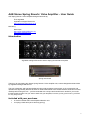
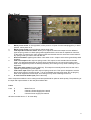
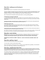
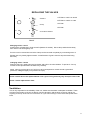
AAE Stereo Spring Reverb / Valve Amplifier – User Guide
AAE Spring Reverb / Valve Amplifier designed and built by:
Theo Argiriadis
Argiriadis Analogue Electronics
http://www.tube-electronics.co.uk
Manual by:
Dave Pape
http://www.museumoftechno.org
http://www.memoid.co.uk
Introduction
Argiriadis Analogue Electronics Stereo Spring Reverb/Valve Amplifier
Spring reverb tank
Thank you for purchasing this Stereo Spring Reverb / Valve Amplifier unit, custom-designed and hand-built
by Argiriadis Analogue Electronics.
This unit is bespoke, and has been designed using purely analogue components, so its construction and
operation are significantly different to those of off-the-shelf effects units. Please read this instruction manual
carefully before using the unit – you’ll be rewarded with a unique and beautiful sonic toolkit for your music.
It’ll take a while to learn how you want to work with your amplifier, but once you’ve got to know it, you’ll find
it’s very easy to love.
Included with your purchase
•
•
4u rack-mountable AAE valve amplifier/distortion unit
2 x spring reverb tanks (short and long spring)
1
Rear Panel
1.
2.
3.
4.
5.
6.
7.
8.
Mains power switch: in the up position, mains power is off (even if mains lead plugged in); in down
position, mains power is on.
Mains power socket: connect UK 240v mains power here.
Tank impedance selector switch: allows you to adjust the tank send output to match different
types of spring reverb unit. Both spring tanks supplied with the unit have an impedance of 8 ohms,
so the switch is preset to this value. Always make sure that this switch is set to the correct value for
any spring reverb you wish to use with the unit.
Ground lift switch: applies ground lift to unit’s audio circuit – helps to solve some ground loop audio
problems.
Tank send output: audio output to spring reverb. This output is not a standard line level audio
output; it is designed specifically to drive a spring reverb tank. Do not connect this output to any
other audio equipment (mixers or effects processors), since doing so may result in damage to your
equipment.
Out: main audio output (to mixing desk etc). This output is nominally at line level, but the unit is
capable of generating very loud signals.
Tank return input: audio input from output of spring reverb unit. This input is designed to receive
the low-level output of a spring reverb – it is not a standard line level audio input. Do not plug any
other audio equipment into this input, since doing so may result in damage to the unit.
In: main line level audio input (from instrument)
Note: components within the unit’s casing have been positioned for optimum audio quality. The positioning of
the input and output sockets on the rear panel reflects this.
Fuses
Fuse
A
B
C
D
Mains Fuse 1A
Channel 1 Power Supply fuse 100mA
Channel 2 Power Supply fuse 100mA
Common Power supply fuse 250mA
All fuses are slow blow or ‘T’ for time delay.
2
Front Panel
1
2
3
4
5
6
7
8
9
10
11
Master Drive knob: controls signal level to tank send output (see rear panel: 5), and how hard the
unit’s amplification/distortion stage is driven.
Input gain switch: When switched up, input signal is attenuated by around 18dB, so the
amplification/distortion stage is driven at lower volume. When switched down, the
amplification/distortion stage is driven at full volume.
Amplifier knob: controls how much of the amplified/distorted signal is passed to the unit’s output
mix.
Reverb bass/treble cut switches: these switches allow you to filter the signal coming into the unit
at the tank return input (see rear panel: 7), optionally cutting low and high frequencies from that
signal.
Reverb level: this knob controls the level of the reverb signal passed to the unit’s output mix.
Original level: this knob controls the level of original, unaffected, signal passed to the unit’s output
mix.
Effect switch: when up, the unit’s reverb and amplification/distortion stages are muted.
Master Out knob: controls the overall level of the unit’s output mix.
Triode/Pentode valve mode switch: selects the unit’s amplification/distortion mode.
Standby/mains switch: when up, unit is in standby mode. Always set to standby (up) when
plugging in and switching on the unit at the rear panel. Only set the standby/mains switch to the
mains position 30 seconds or so after turning on the mains: this will give the valves in the unit time to
warm up.
Mute button: this button mutes the output of the channel. This is very useful for avoiding potentially
very loud “clicks” when changing settings. Always press the mute switch and hold it in while
changing valve mode, turning effect on/off, or changing the input gain setting.
3
Operation: setting up and turning on
Preparation
Before turning the unit on, turn all knobs on the front panel fully anti-clockwise.
The unit is capable of producing very high output levels and, if you send a high input signal through it, might
generate enough of an output to damage your mixer, amp, speakers or ears. It’s best to start quietly and
gradually turn levels up, so that you keep control of the unit’s overall output level.
Also, ensure that the front panel’s stand by/mains switch is in the up (standby) position.
Connecting a spring reverb tank
To connect a spring reverb, plug the 0.25” jack plug of a mono jack-phono cable into the main unit’s tank
send output. Now plug the cable’s phono plug into the IN socket of one of the spring reverb tanks provided
with the unit.
Plug the phono plug of a second jack-phono cable into the spring tank’s OUT socket, and plug that lead’s
jack plug into the main unit’s tank return input (see rear panel: 7).
Powering up the unit
Plug a mains “kettle” lead into the power input socket on the unit’s rear panel (see rear panel: 2 above).
Now, switch on (down) the mains power switch on the unit’s rear panel (see rear panel: 1 above). The red
LED on the unit’s front panel will light up.
Leave the unit to warm up for about 30 seconds. During this time, the unit’s valves will reach their optimum
working temperature, and will glow gently inside the case.
Now set the front panel’s stand by/mains switch (front panel: 10) to its down (mains) position. The unit is now
fully powered up, and the front panel’s green LED will light up. The unit is now ready for use.
Operation: mute buttons
Important: when changing valve mode (triode/pentode), changing the setting of the input gain switch, or
setting the effect switch, press and hold in the mute button of the relevant channel. This precaution is
necessary because sudden changes in signal volume can cause very loud pops in the unit’s output.
THE MUTE BUTTONS ARE THERE TO PROTECT YOUR OTHER AUDIO EQUIPMENT AND YOUR
EARS.
Operation: getting a signal
Start with all front panel knobs turned fully anti-clockwise.
Turn the master out knob clockwise about halfway.
With an audio signal connected to the unit’s in socket, turn the original knob up gradually. You should hear
some of your audio signal, unaffected, coming through the unit.
Operation: amplification/distortion
First, check that the effect switch is down, so that the unit’s amplification/distortion stage is not muted.
Turn all knobs fully anti-clockwise. Now turn up the amplifier knob and the master output knob about halfway
Gradually turn up the master drive knob to drive the mini power valve amp inside the unit.
The master drive knob controls the drive level in a triode or pentode (switchable) amplifier/distortion stage.
Turning up the master drive level drives the unit’s amplification/distortion stage harder, and can produce
some very hard distortion effects, especially with high-level inputs from, for example, professional audio
equipment or a CD player.
4
“A mini power valve amp drives the ‘reverb tank’. If the effect switch is up – only original sound comes in.
This amp in high master drive settings also produces non-reverberated valve distortion type of sound, similar
to a distortion unit. This distortion can be anything from smooth to crunchy to extreme. Again, it all depends
on how the gain switch and master drive are set. The amplifier control mixes the signal from the output
transformer of this amp before it reaches the input of the reverb tank.”
The input gain switch gives you another way to control the drive level of the unit’s amplification/distortion
stage. In its up position, the unit’s audio input is cut by about 18dB, allowing you to create subtle, gentle
distortions. When switched down, the unit’s amplification/distortion stage operates at full level, so will tend to
produce harder, more aggressive distortions.
The triode/pentode switch allows you to control the valve mode of the amplification/distortion stage. Triode
and pentode valve amplifiers impart sound with different tonal qualities and introduce different types of
distortion, so this switch gives you further control over the colour and tone of the unit’s output.
Between the master drive, the input gain switch and the triode/pentode valve type switch, the unit gives you
great flexibility in terms of amplification/distortion effects.
The amplifier knob controls the level of the amplified/distorted signal in the unit’s output mix.
Switching the effect switch to its up position mutes the amplification/distortion effect.
Operation: reverb
First, check that the effect switch is down, so that the unit’s reverb and amplification/distortion stages are not
muted.
Turn all knobs fully anti-clockwise.
Now turn up the reverb knob and the master output knob about halfway. This ensures that some of the signal
returning from the spring reverb is passed to the unit’s output mix.
Gradually turn up the master drive knob to drive the spring. Soon, you will hear the reverb signal in the unit’s
output mix.
At higher input levels and/or master drive settings, you can create grungy, distorted reverbs by driving the
spring so hard that the signal distorts on its way into the spring. Be careful with this: too much overdriving
may reduce the lifespan of the spring reverb because, while the springs themselves are tough, they’re driven
by a delicate transducer coil (the little component attached to the springs at the input end) which can burn
out if driven too hard for too long.
The bass cut and treble cut switches allow you to filter out low and high frequency sound from the reverb
signal, controlling the colour of the reverb effect.
Setting the effect switch to its up position mutes the unit’s reverb stage.
WHEN THE EFFECT SWITCH IS DOWN THE AMPLIFIER CONTROL, REVERB AND ORIGINAL KNOB
FORM A MIXER TO CONTROL THE THREE CORRESPONDING SIGNALS I.E. AMPLIFIED (OR
DISTORTED), REVERBERATED AND ORIGINAL. WHEN EFFECT SWITCH IS UP BOTH AMPLIFIER,
AND REVERB SIGNAL ARE MUTED.
5
Sound and possible applications
This section is written from the point of view of a musician using the unit. It comprises a set of notes based
on my own experience of this unit and a similar distortion box which Theo designed for me some months
ago, and discussions with other musicians on AAE’s client list.
Triode vs Pentode amplification
Triode amplification and distortion sound subjectively warmer and more transparent, and to me more
“natural”, than pentode.
If you want a smooth fattening of a sound, my starting point would be triode mode. If, however, you want a
harsher, more brutal effect, hard pentode distortion can sound extremely aggressive and brittle.
Adding “valve warmth” to digital sound
I personally think that simply passing a signal from a digital source (like a PC soundcard or a digital synth or
sampler) through AAE valve circuitry makes it sound warmer, thicker, and plummier. Even the original signal
passes through some valve circuitry, and I will often record digitally generated sound through my own AAE
box without any distortion to add subjective warmth to recordings.
I imagine that this effect would well work across the board: with vocals, acoustic instruments, analogue and
digital synths, and whole mixes. Currently, valve mixers are selling for many thousands of pounds because
producers want to introduce “valve warmth” to their recordings. I believe AAE products do this very well
indeed.
Gentle distortion
Another way I commonly use my own AAE distort box is to send a moderate signal into it, turn the master
drive knob to about 15%, and switch the input gain to further attenuate the input. This lets through a fairly
clean sound, with just a hint of distortion on peak signals.
I then mix this gently distorted signal with some of the original. This effect adds warmth and a little sustain to
signals. Very good with synth drones, pads and ambiences, but I’d recommend investigating with all kinds of
signal: with the right settings, you can make effects in which distortion harmonics fade in and out gradually,
adding (I think) very beautiful movement to pads and atmospheres.
Hard distortion
Higher master drive settings will create harder, harsher distortions (remember to turn down the amplifier and,
if necessary, the master out knobs to compensate). As mentioned before, pentode amplification/distortion
mode gives an even more abrasive sound.
Don’t be surprised if bassy originals sound thinner when severely distorted: hard distortion introduces a large
amount of extra high-frequency sound, which will drown out some bass.
I know of another AAE user who processes sounds through a heavily distorting AAE box, and mixes just a
tiny amount of the distorted signal with the clean original. This hint of extreme distortion has the effect of
adding “sparkle” to the sound, and the effect is different to adding a lot of mild distortion.
Similarly, in the past I’ve created ultra-distorted drones and mixed them into my music very, very low so that,
even though the sound itself is shattered and caustic, the overall effect can be quite delicate and beautiful.
But I’ve also played with harsh pentode distortion on percussive sounds – and that can sound amazing.
A few notes on distortion from a non-technical musician
Distortion works by introducing extra harmonics/overtones into an audio signal.
If you feed a very harmonically pure signal into the unit – like a single plucked guitar string, or a sine wave
from a synth – you’ll hear a very pure kind of distorted result. It won’t sound crackly, just brighter and
sharper. An obvious example that springs to mind is the guitar riff at the start of the Guns ‘n’ Roses track
“Sweet Child of Mine”: although it’s very, very distorted, the guitar sound is very clean – because the
arpeggio the guitarist’s playing consists of one note at a time.
6
As you feed more complex, harmonically-rich signals into the unit – complex chords, complex waveforms or
whole mixes – the distorted result will sound more glitchy, noisy and crushed, because of all the clashing
extra harmonics produced as a result of the distortion.
Guitar power chords tend to consist of a small number of notes with simple harmonic relationships, like fifths
and octaves – so they contain a moderately simple harmonic mix. They sound fantastic when they distort
because of the way the extra distortion harmonics interact with each other and with the harmonics of the
original sound. Enough complexity to bite, but not so complex that the distorted result sounds like it’s
breaking up.
Again, I recommend playing with lots of different input signals. Get to know how your unit behaves with
harmonically simple and harmonically complex inputs.
Clean spring reverb
Setting the input switch up (lowering the input level) and the master drive fairly low, carefully turn up
the unit’s master out, reverb and original knobs to mix clean spring reverb with your original sound.
This effect works particularly well with percussive noises – you’ll hear sudden transient signals wobbling the
spring.
You can turn down the original signal completely so that the unit’s output mix contains only reverb. This
setting allows you to use the unit as a spring reverb send effect.
Reverb times
Shorter springs generally mean shorter reverb times, so you can get different effects from the two spring
tanks that come with the unit.
Colouring and damping reverb
The unit’s bass and treble cut switches are useful for making reverbs sound less boomy or harsh, and used
together will help the reverb sound sit less obtrusively in your mix.
I’ve also experimented with damping the reverb with a small piece of foam sponge sitting on top of the spring
itself. This works well with percussion: you’ll hear the characteristic spring wobble without the more diffuse
reverb “tail” at the end.
Extreme spring reverb
Because you have access to open spring reverb tanks, you’ll need to take care looking after them, but you
can create crazy sounds – totally unachievable in software or with digital equipment – by gently twanging the
springs or running a coin along them.
Be gentle – while the springs themselves are resilient, the transducer used to drive them is more delicate.
7
Extra Operating and Care Notes
Ground Lift Switches
Under normal circumstances these switches must always be on i.e facing downwards. If they are
accidentally turned off a loud hum will be heard. If the ground lift switches are tried turn the volume or input
level of the mixing desk as low as possible because this hum could damage what the unit is driving. (Tape
has been put on them to keep them down.)
Reverb Springs
Both of the reverb tanks house an input impedance of 8 ohms. Therefore make sure that the input
impedance selector switch is always set onto 8 ohms. This is why there is tape on the back to keep them up.
The jack to phono lead that drives the input of each spring has to be treated more like a speaker lead i.e a
high level signal lead (ordinary good quality jack to phono lead and make sure they are in good working
order). You must also always make sure that it is properly connected. The link between the send out of the
unit and input of the spring is a very important one. This is because valve amplifiers with output transformers
such as the one’s inside this unit must never be left with their outputs open circuited. If this happens
components in the unit could be damaged. Makesure before turning on the unit that the send/out is
connected to the tank input.
The second jack to phono lead which makes a link between tank output and tank return of the unit is an
ordinary screen jack to phono lead.
This unit can drive the springs really hard and as a result you can obtain this very characteristic, unique type
of reverb distortion. This can be achieved by turning up the master drive and using the reverb to control the
level of reverberated distorted signal.
Very occasionally however, springs might fail because the coils of the spring are very tiny and get warm. To
make sure this doesn’t happen check the output of the reverb by turning the reverb fully clockwise and
setting the master drive to a very low level and then hear the reverberated signal. i.e never go onto full
master drive immediately.
Beware if you turn the impedance selector switches to 600 or 1000 ohms and you do not connect them to
the tank input, we should always do. If a signal is running through the unit, one might get a small electrical
shock if you touch the tips of the phono side of the lead.
Accutronics reverb tanks can be obtained from the Tube Amp Doctor. (http://www.tubeampdoctor.com/)
When testing the unit the treble and bass cut switches must always be off. They only apply to the
reverberated signal. You can cut the base or the treble at your choice.
When downwards, the gain switch gives approximately an extra 18db’s of gain. It’s a good idea when
starting to operate the unit, that the gain switch is in the up position. (With less gain you can have finer
control of the master drive). Once you get used to it you can go for the extra gain, depending on the input
source i.e if it’s a microphone you’ll need extra db’s.
8
REPLACING THE VALVES
1
3
Screw A
1 ECC82 or 12AU7 or 5814A
2 ECC83 or 12AX7 or 7025
Clamp
3 PCL86
4 PCL86
2
4
Screw B and Washer
FRONT
Changing valves 3 and 4
Loosen screw A (break glue). Undo screw B (beware of washer). Move clamp anticlockwise away
from valves. Pull valves gently out.
If unit is not to be moved about a lot the clamp can be removed completely by unscrewing screw A.
(Please note only loosely tighten screws. A small amount of glue is used to stop the screw being
too loose.)
Changing valves 1 and 2
Remove caps. Very gently twist anti-clockwise and pull on the valve holders. To put back – line up
notches to the caps and twist clockwise very carefully.
Again, caps do not have to be on if unit is not to be transported or moved around a great deal.
(However, it may be slightly noisy without the caps).
Valves 3 and 4 have to be replaced about once a year if using unit every day. Cost per valve £1.50
Valves 1 and 2 replaced less often.
Ventilation
This is very important for the reliability of the unit. Make sure that there is adequate ventilation. There
are feet on the bottom of the unit so that air can flow through it and the slots on the top. Never put
anything on the top of the unit. Do not leave it on if you are not using it. Leave some free space at the
back.
9


![View User`s Manual [US] - Acoustic Amplification](http://vs1.manualzilla.com/store/data/005834670_1-839e21e8bc31a6b298042e7e04804c8b-150x150.png)