1
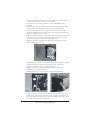
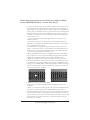
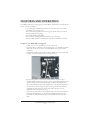
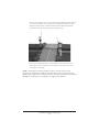
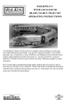
HO Crossing Gate
PLEASE READ THE MANUAL BEFORE USE AND SAVE
WWW.MTHHOTRAINS.COM
TABLE OF CONTENTS
OVERVIEW
3
UNPACKING
4
Removing and Unwrapping Your Engine
What Else is in the Box?
4
4
SELECTING THE INSTALLATION SITE
4
SET-UP
5
6
8
8
9
10
Master/Slave Motor Installation
Speaker Installation
Sensor Installation
Molded Roadbed Track
Not Molded Roadbed Track
FEATURES AND OPERATION
To operate your MTH HO Crossing Gate
11
11
SPECIFICATIONS
13
SPEED TO DISTANCE CHART (1/87 SCALE)
13
SERVICE & WARRANTY INFORMATION
14
14
14
Service & Warranty Information
Limited One-Year Warranty
CAUTION: ELECTRICALLY OPERATED PRODUCT:
Recommended for Ages 14 and up. Not recommended for children under 14 years of age without adult supervision. As
with all electric products, precautions should be observed during handling and use to prevent electric shock.
WARNING: When using electrical products, basic safety precautions should be observed, including the following:
Read this manual thoroughly before using this device.
l
M.T.H. recommends that all users and persons supervising use examine the hobby transformer and other electronic equipment
periodically for conditions that may result in the risk of fire, electric shock, or injury to persons, such as damage to the primary cord,
plug blades, housing, output jacks or other parts. In the event such conditions exist, the train set should not be used until properly
repaired.
l
Do not operate your layout unattended. Obstructed accessories or stalled trains may overheat, resulting in damage to your layout.
l
This train set is intended for indoor use. Do not use if water is present. Serious injury or fatality may result.
Do not operate the hobby transformer with damaged cord, plug, switches, buttons or case.
l
®
Atlas True-Track is a registered trademark of Atlas Model Railroad Co., Inc.
This product may be protected by one or more of the following patents: 6,019,289; 6,280,278;
6,281,606; 6,291,263; 6,457,681; 6,491,263; 6,604,641; 6,619,594; 6,624,537; 6,655,640.
©2010, M.T.H. Electric Trains®, Columbia, MD 21046
CROSSING GATE OPERATION OVERVIEW
The MTH HO Crossing Gates will operate on AC or DC input power.
(10 – 21 VAC or 10 – 18 VDC).
The MTH HO Crossing Gates are bi-directional and can sense train movement on
1 to 4 individual tracks at a grade crossing. The moveable barricades and warning
bell are controlled by a pair of sensors placed between the rails of each track being
protected by the crossing gates. One sensor of each pair is placed on the approach
side of the grade crossing and the 2nd sensor of each pair is placed on the
departure side of the grade crossing. Since the operation is bi-directional, it does
not matter which of the sensor of each pair is placed on which side of the grade
crossing.
When a train covers the sensor on the approach side of the grade crossing, the
warning bell will begin to sound and the barricades will lower from the vertical
position to the horizontal position. The barricades are designed so that when they
are lowered to the horizontal position, they will block the automobile traffic from
crossing the track(s) until it is safe to do so.
What is important is the spacing of the sensors. The spacing is dependent on the
maximum speed of the trains passing over the grade crossing. Proper placement of
the sensors will assure that the barricades will be fully lowered when the train
arrives at the grade crossing. A chart is provided on page 13 in this manual to help
determine the correct spacing of the sensors for a given maximum speed on your
railroad.
The sensors are prewired for connection to the master motor enclosure and can be
separated by about 4 feet. That is 2 feet on either side of the grade crossing. If you
situation requires the sensors to placed farther form the grade crossing additional
wire can be spliced between the sensor and the connector of each sensor pair.
If a second, third or even a fourth train reaches the detection area for the grade
crossing while the first or any of the other trains are still in the detection area, the
barricades will remained lowered and the warning bell will continue to ring until all
trains have cleared the detection area.
M.T.H. HO Operating Crossing Gate
3
UNPACKING THE CROSSING GATES
Removing and Unwrapping Your Product
Carefully remove and unwrap the product from the packaging.
What Else is in the Box?
Instruction Manual (The one you are reading)
Masts (2) with the short barricade
arms attached (Use for 2 lane roads)
Long Barricades (2) (Use for 4 lane roads)
Master Motor Enclosure
Metal Setup Template
Speaker with Enclosure
·Slave Motor Enclosure
Multiple Track Signs
Sensors (4 Pairs)
Interconnect Cable
Wires for Power Connection
Screws
SELECTING THE INSTALLATION SITE
Obviously your scenery or scenery plan will have a major impact on the location of
your HO Crossing gates. However when selecting a location you must also consider
what is located under your benchwork.
·
·
·
·
Make sure that there is sufficient space without obstructions under the
benchwork. The amount of space required will depend on the number of
parallel tracks that separate the crossing gates.
Take into consideration any edging or bracing material.
Make sure that the connections and sensitivity control on the master
motor unit and the connections on the slave motor unit.
Make sure that you have a suitable location for mounting the speaker
M.T.H. HO Operating Crossing Gate
4
SET UP GUIDE
Now that you have the crossing gates unpacked select the location for installation.
The MTH HO Crossing Gates have the ability to detect train movements on up to 4
tracks.
To install the MTH HO Crossing Gates the following items are required:
·
15/64” drill bit (for fit into ties and track that has a roadbed)
· 1/4” drill bit (for fit directly into the layout or scratch built roadbed)
· 1/8” drill bit (for pilot holes)
· #1 Philips screwdriver
· X-acto knife
The following provides instruction for installing your MTH HO Crossing Gates on
your layout. Follow the directions in order, starting with the mast installation.
First determine if grade crossing will be a 2 lane road or 4 lane road.
The barricades that are mounted to the masts in the packaging are for 2 lane roads.
If you have a 4 lane road at the grade crossing you will want to remove the short
barricades and install the longer barricades supplied in the packaging.
To change the barricades, remove the installed barricade by pulling it out of the
mast pivot. Then push the replacement barricade into the hole in the mast pivot.
The MTH HO Crossing Gates can detect train movement on 1, 2, 3, or 4 track
simultaneously, just as the prototype railroads do with their grade crossings signals
and gates. Just as in the prototype MTH has provide removable signs with
indications for the number tracks at the grade crossing. The signs are held in place
on the mast with a molded in pressure clamp. The signs are easy to remove and
replace.
M.T.H. HO Operating Crossing Gate
5
Master/Slave Motor Installation
1. Using the metal setup
template provided, mark the
location for drilling the screw
holes and the pass through hole
for the actuating wire rod. Do
not drill through the holes in the
template.
Note: The metal template should be
placed against the rails closest to the mast location. The rails were chosen as
reference to avoid variances since some layouts have track with built in roadbed or
those that may have ballast applied as opposed to track without roadbed or
ballast.
2. Drill 1/8” pilot holes for the mounting screws (2 for each mast and 4 for
each motor enclosure).
A Helpful Tip – Use a marker or pencil to circle the mounting holes for the motor
enclosures on the underside of the layout while the drill bit is still protruding
through the underside of the layout surface. This will make locating them easier.
3.Using a 3/8” drill bit drill the pass through hole for the actuating wire rod.
A Helpful Tip – Before mounting the motor enclosures
to the underside of the Layout, back out the clamping
screw in each motor enclosure so that actuation wire
rod will slide easily through the clamp during
installation.
4. Align the mounting tabs on the motor
enclosure with the pass through hole and the
pilot holes, then attach the motor enclosure(s)
to the underside of the layout using the screws
provided.
5. Follow the same procedure for the slave motor enclosure
6. Insert the wire harness of one of the masts through the 3/8” hole in the
layout and guide the actuating wire rod through the clamping hole in the
master motor assembly.
M.T.H. HO Operating Crossing Gate
6
7. Make sure that the electrical cable does not interfere with the movement
of the actuation rod, or contact any moving parts.
8. Secure the mast to the layout with two of the small Phillips screws
provided.
9. When the mast is secured, gently move the barricade arm up and down
while checking that the barricade arm moves up and down freely.
10. If the barricade arm is not moving freely the mast may need to be
maneuvered slightly for better alignment of the actuating rod. If the arm
is moving freely move on to step 11.
11. When the barricade arm is moving freely, make sure that the barricade is
at the end of the vertical travel, then tighten the clamping screw on the
motor actuating arm to secure the actuating wire rod.
12. Remove the cover from the motor enclosure by pushing up on the 2
tabs and pulling on the cover
13. Thread the 3-wire cable from the mast through the small square opening
in the motor enclosure and connect the cable to the 3-pin header
connector on the pc board in the motor enclosure.
14. Make sure that wires are not interfering with any moving parts.
15. Replace the motor enclosure cover
16. Repeat the steps 6 to 15 for the other mast and barricade arm.
17. The 5-wire harness is the interface between the master motor enclosure
and the slave motor enclosure. Connect one end of the 5-wire harness to
the 5-pin header in the master motor enclosure and the other end to the 5pin header in the slave motor enclosure.
M.T.H. HO Operating Crossing Gate
7
18. When activated, the barricade arm is designed to travel from a vertical
position to a horizontal position. 90 degrees of travel. Should the
barricade arm(s) need to be adjusted, loosen the clamping screw on the
actuating arm, move the barricade arm or the wire rod slightly and
retighten the clamping screw.
Speaker Installation
Find a suitable location to affix the speaker and speaker enclosure, either under the
layout or on top of your layout in a building or hiding in scenery.
1. The speaker enclosure has 2 mounting holes in the back of the enclosure.
Attach the enclosure using 2 of the screws included.
2. Push the speaker into the enclosure.
Sensor Installation
The four sensor pairs provided allow you to monitor train movements on up to track
to control the operation of the MTH HO Crossing Gate. There are two main types
of track configurations. One type has the roadbed included or attached to the track
(also includes hand laid ballast). The second type does not have a roadbed attached or
included. The instructions will explain both.
M.T.H. HO Operating Crossing Gate
8
Follow these instructions for track that has a molded roadbed,
such as MTH HO RealTrax® or Atlas True-Track®:
1. Start by noting the two track sections that will be receiving the sensors.
The sensors are pre-wired and can be separated to a span of about 4 ft.
Please reference the speed to distance chart on page 13 to determine the
spacing that you will need to have the gates come to the lowered position
before the train arrives at the crossing. Keep in mind that you will have
consider the reaction time of the crossing gate when determining where
to place the sensors.
- Once a sensor is covered it takes approximately 9 seconds for the
barricade to lower.
- After the second sensor is cleared 14 seconds will elapse before the
barricades are completely raised. The bell stop ringing 22 seconds after
the second sensor is uncovered.
2. On both sides of the grade crossing mark the locations in the track
where you want the sensors to be located. It is recommended that you
mark as close to the centerline between the rails as possible and locate
the hole in the ballast space two between ties.
3. Drill a small pilot hole using a 1/8” drill bit at the spot you marked in
step 2. Take care to ensure you aren't drilling through any wiring. Drill
completely through the track section and into your benchwork.
4. Repeat the same procedure on the other piece of track you marked
5. Remove both sections of track from your layout. You will notice there
is a small hole in your layout decking from the pilot you drilled in step 3
6. Using a 5/16” drill bit drill a hole through the layout decking at the spot
where your pilot mark is. This is the hole you're going to use to run the
sensor up to your track sections
7. Repeat step 6 on the other track section
8. Using the X-acto knife clean the plastic burrs from the holes in the
track bed.
9. Insert one of the sensors through the hole in the layout and then insert
the sensor in the hole in the track roadbed. Make sure the sensor is
inserted completely so that the step on the sensor enclosure touches the
bottom of the roadbed. At this point the sensor should be even with the
tops of the ties in your track. You may find that you need to run the drill
bit in and out of the hole a little more to make the sensor fit. Do not
make the hole too large.
M.T.H. HO Operating Crossing Gate
9
10. Once you have the fit correct, repeat this on the other track section.
11. Place the track pieces with the sensors back in place on your layout
taking care to ensure you do not clamp the wire under the track.
12. You may want to secure the wires to the underside of the bench work
with wire clamps, staples or tape to make sure that the sensor stay in
place.
13. Plug in the sensor pair on the Master Enclosure at the location marked
Sensor 1
Repeat these steps for each track you want to have sensors installed. For example,
track 2's sensors would plug into the Sensor 2 position on the Master Enclosure.
Track 3 to Sensor 3 and Track to Sensor 4
Follow these instructions for track that does not have a molded
roadbed or track that is already ballasted:
1. Start by noting the two track sections that will be receiving the sensors.
The sensors can be separated to a span of about 4 feet. Please reference
the speed to distance chart on page 13. If you desire a wider span on the
sensors you can splice in an wire extension to do this.
2. Mark the two locations on the track where you want the sensors to be
located. It is recommended that you mark on the centerline between the
rails and in the space between the ties.
3. Drill a small pilot hole using a 1/8” drill bit at the spot you marked in
step 2. Take care to ensure you aren't drilling through any wiring. Run the
drill bit through the track section and into your layout Benchwork.
4. Repeat the same procedure at the location of the second sensor that you
marked.
5. Using a ¼” drill bit drill through your layout or roadbed taking care to
not distort the ties. You may want to hold the ties in place with a pair of
pliers or tape them down so they do not break or twist while drilling.
6. Repeat step 5 at the second sensor location.
7. Using the X-acto knife clean up any burrs that remain on the ties.
8. From underneath your layout slide the sensors up through their
respective holes until the face of the sensor is flush with the tops of the
ties.
9. You may want to secure the wires to the underside of the bench work
with wire clamps, stapes or tape to make sure that the sensor stay in
place.
10. Plug in the sensor pair on the Master Enclosure at the location marked
Sensor 1.
11. Repeat these steps for each track you want to have sensors installed. For
example, track 2's sensors would plug into the Sensor 2 position on the
Master Enclosure. Track 3 to Sensor 3 and Track to Sensor 4.
M.T.H. HO Operating Crossing Gate
10
FEATURES AND OPERATION
Your MTH Operating Crossing gate provides realistic operation for your HO layout.
Here is a list of the features:
· Four sensor pairs included which means you can have up to four tracks
controlling your crossing gates
· The sensors work in pairs so the crossing gates know where your train is
and will operate prototypically
· Has realistic flashing red LED's
· Plays a realistic warning bell sound when the gates are active
· Has removable Number of Tracks plate and decals to indicate 2-4 tracks
To operate your MTH HO Crossing Gate:
1. Make sure all of the installed sensors are uncovered.
2. Connect either 12-18VAC to the AC Input jack or 12-18VDC to the DC
Input jack. If all of the sensors are unblocked then the gates should
remain up.
3. Adjust the sensitivity pot so that it's in the middle of its travel. This will
provide “normal” sensitivity for the average lit room.
4. To test the operation, run a train on the track that has the sensors
installed. When the engine covers the sensor on the approach side of the
grade crossing the bell sound should play, the lights should flash, then
after a short delay the barricades should move to the horizontal position.
5. As the train moves through the grade crossing, the barricades should
remain down until the last car of the train clears the sensor on the
departure side of the grade crossing.
6. Once the second sensor is cleared (both sensors are now uncovered) the
barricades should begin to go back to the vertical position. Once the
barricades are fully vertical, the lights and bell will shut off after short
delay.
M.T.H. HO Operating Crossing Gate
11
7. If the crossing gates on your layout are protecting multiple tracks and one
or more of the sensors are covered, the bell sound will continue to play.
The lights will continue to flash and the barricades will remain down.
Once all sensors are cleared, the gates will go back up.
8. If you have a dimly lit room you may find that your sensors are not
detecting the train. To increase the sensitivity of the sensors turn the
sensitivity pot clockwise.
NOTE – Turning the sensitivity pot fully clockwise sets the sensors to max
sensitivity. In a normally lit room this will most likely be too sensitive and some
shadows may trigger your crossing gate actions. You may need to make a couple of
adjustments to the pot to get it right for your lighting environment.
M.T.H. HO Operating Crossing Gate
12
Specifications
Physical
Electrical
Master/Slave Enclosure
Height
Width
Depth
80.00mm
74.00mm
75.00mm
Masts
Heigth
Width
Depth
Gate Arm Length(short)
Gate Arm Length(long)
54.3mm
13.4mm
21.2mm
55.6mm
95.6mm
Input Voltage
AC
DC
10-21VAC
10-18VDC
Speed to Distance Chart (1/87 scale)
Commanded Speed (sMPH)
1
2
5
10
15
20
25
30
35
40
45
50
55
60
65
70
75
80
85
90
95
100
105
110
115
120
HO Scale Speed (in/sec)
0.20
0.40
1.00
2.00
3.00
4.00
5.00
6.00
7.00
8.00
9.00
10.00
11.00
12.00
13.00
14.00
15.00
16.00
17.00
18.00
19.00
20.00
21.00
22.00
23.00
24.00
M.T.H. HO Operating Crossing Gate
13
Service & Warranty Information
How to Get Service Under the Terms of the Limited One-Year Warranty
When you suspect an item is defective, please check the operator's manual for standard operation and troubleshooting techniques that may correct the problem. Additional information may be found on the M.T.H. Website.
Should you still require service, follow the instructions below to obtain warranty service.
First, e-mail, write, call or fax a M.T.H. Authorized Service Center (ASC) in your area to obtain Repair
Authorization. You can find the list of ASCs on the M.T.H. Website, www.mth-railking.com. Authorized
Service Centers are required to make warranty repairs on items sold only from that store; all other repairs may-or may not be done at the store's own discretion. If you did not purchase the item directly from the ASC, you
will need to select a National Authorized Service Center (NASC). These centers are compensated by M.T.H. to
perform warranty service for any customer whose repair qualifies for warranty service. A list of NASC retailers
can be located on the M.T.H. Website or by calling 410-381-2580. Should the warranty no longer apply, you may
choose either an ASC or NASC retailer to service your M.T.H. Product. A reasonable service fee will be
charged.
CAUTION: Make sure the product is packed in its original factory packaging including its foam and plastic
wrapping material to prevent damage to the merchandise. There is no need to return the entire set if only one
of the components is in need of repair unless otherwise instructed by the Service Center. The shipment must be
prepaid and we recommend that it be insured. A cover letter including your name, address, daytime
phone number, e-mail address (if available), Return Authorization number (if required by the service
center, a copy of your sales receipt and a full description of the problem must be included to facilitate
the repairs. Please include the description regardless of whether you discussed the problem with a
service technician when contacting the Service Center for your Return Authorization.
Please make sure you have followed the instructions carefully before returning any merchandise for service.
Authorized M.T.H. Service Centers are independently owned and operated and are not agents or representatives
of M.T.H. Electric Trains. M.T.H. assumes no responsibility, financial or otherwise, for material left in their
possession, or work done, by privately owned M.T.H. Authorized Service Centers.
If you need assistance at any time email MTH Service at [email protected], or call 410 381-2580.
Limited One-Year Warranty
All M.T.H. products purchased from an Authorized M.T.H. Retailer are covered by this warranty.
See our Website www.mthtrains.com to identify an M.T.H. Retailer near you.
M.T.H. products are warrantied for one year from the date of purchase against defects in material or
workmanship, excluding wear items such as light bulbs, pick-up rollers, batteries, smoke unit wicks, and traction
tires. We will repair, replace, or credit (at our option) the defective part without charge for the parts or labor, if
the item is returned to an M.T.H. Authorized Service Center (ASC) or M.T.H. National Authorized Service
Center (NASC) within one year of the original date of purchase. This warranty does not cover damages caused
by improper care, handling, or use. Transportation costs incurred by the customer are not covered under this
warranty.
Items sent for repair must be accompanied by a return authorization number, a description of the problem, and
a copy of the original sales receipt from an Authorized M.T.H. Train Merchant, which gives the date of
purchase. If you are sending this product to an Authorized Service Center, contact that Center for their return
authorization.
This warranty gives you specific legal rights, and you may have other rights that vary from state to state. Specific
questions regarding the warranty may be forwarded to M.T.H. Directly.
Service Department:
M.T.H. Electric Trains
7020 Columbia Gateway Drive
.Columbia MD 21046-1532