1
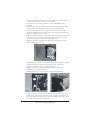
7. Make sure that the electrical cable does not interfere with the movement
of the actuation rod, or contact any moving parts.
8. Secure the mast to the layout with two of the small Phillips screws
provided.
9. When the mast is secured, gently move the barricade arm up and down
while checking that the barricade arm moves up and down freely.
10. If the barricade arm is not moving freely the mast may need to be
maneuvered slightly for better alignment of the actuating rod. If the arm
is moving freely move on to step 11.
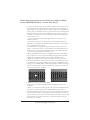
11. When the barricade arm is moving freely, make sure that the barricade is
at the end of the vertical travel, then tighten the clamping screw on the
motor actuating arm to secure the actuating wire rod.
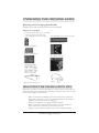
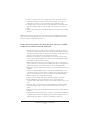
12. Remove the cover from the motor enclosure by pushing up on the 2
tabs and pulling on the cover
13. Thread the 3-wire cable from the mast through the small square opening
in the motor enclosure and connect the cable to the 3-pin header
connector on the pc board in the motor enclosure.
14. Make sure that wires are not interfering with any moving parts.
15. Replace the motor enclosure cover
16. Repeat the steps 6 to 15 for the other mast and barricade arm.
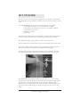
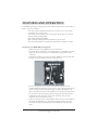
17. The 5-wire harness is the interface between the master motor enclosure
and the slave motor enclosure. Connect one end of the 5-wire harness to
the 5-pin header in the master motor enclosure and the other end to the 5pin header in the slave motor enclosure.
M.T.H. HO Operating Crossing Gate
7