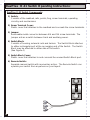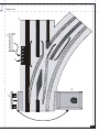
1
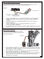
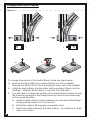
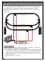
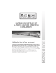
MTH
®
ELECTRIC TRAINS, INC.
7020 Columbia Gateway Drive
Columbia, MD 21046-1532
®
MTH RealTrax switches add flexibility
and reliability to your O Gauge RealTrax
layout. Designed to provide years of
trouble free, smooth operation, RealTrax
switches are the
perfect additions
to expand your
®
RailKing empire.
O-31
S
W
I
T
C
H
Table of Contents
2
Introduction:
3
Switch Operating Instructions:
RealTrax® O-31 Switch Components:
Screw Terminal Definition:
Remote Switch Wiring Instructions:
Basic Switch Operation:
Changing Switch Block Positions:
Accessory Operation From Switch Power Out:
Multiple Connections Under Screw Terminal
4
4
6
7
7
8
9
9
Multiple Switch Operating Instructions (Track Power):
Multiple Switch Operation Through One Remote Switch,
Track Power, Identical Throws:
Multiple Switch Operation Through One Remote Switch,
Track Power, Opposite Throws:
9
9
10
Auxiliary Powered Switch Operating Instructions:
Multiple Switch Operation Through Separate Remote Switches
Multiple Switch Operation Through One Remote Switch,
Auxiliary Power, Identical Throws
Multiple Switch Operation Through One Remote Switch,
Auxiliary Power, Opposite Throws
10
11
11
RealTrax® O-31 Switches In Tubular Rail Layouts:
13
Multiple Train Operation Using Powered/Unpowered Sidings:
14
Troubleshooting
15
Service and Warranty Information
Operating Caution
How to Get Service Under The Terms of The Limited One Year Warranty
Limited One Year Warranty
16
16
16
16
12
Introduction
Thank you for purchasing the MTH Electric Trains RealTrax O-31 Switch. As
with all RealTrax products, you will find the O-31 Switch easy to install into
your layout whether it be a permanent or temporary one. There are no
plastic and/or metal pins to lose or confuse. The setup is simple; with only
three connections of easy to attach connectors and the turn of a screw, your
RealTrax Switch will be up and running in no time!
The RealTrax O-31 Switch performs all of the functions of other switches, but
better. It has a double-microswitch driven non-derailing feature. Inside the
Switch Block (lantern housing) are four powerful but efficient and quiet
solenoid coils that drive the switch points back and forth at a voltage and
current draw as yet unexperienced in model railroading. The RealTrax Switch
operates on only 10Volts and 1.25Amps. It has a spring assisted mechanism
that ensures that the points always will be in the correct position. If you
change directions with a RealTrax Switch, you will not have to worry about
derailments or electrical short circuits.
The RealTrax Switch can be wired for operation via track power or auxiliary
power. Also, you will be able to operate several RealTrax Switches together
by following the appropriate illustrated diagram(s) in this manual. It can be
installed into a layout to have powered and unpowered sidings for multiple
train operation (see figure 14).
The RealTrax O-31 Switch is constructed of sturdy ABS plastic, solid extruded
rails and simple yet sturdy electronics. The design has been streamlined with
features like a Switch Block Cover that hides the opening to the switch's
underside and a Screw Terminal Cover that hides the traditionally unsightly
yet necessary wire connections. The design follows other RealTrax items so
that it blends into your layout, instead of standing out. With its ruggedness
and slim styling, the RealTrax O-31 Switch will give you years of trouble-free
operation on either your RealTrax or your tubular rail O-Gauge model
railroad.
3
RealTrax® O-31 Switch Operating Instructions:
RealTrax O-31 Switch Components:
1) Switch:
Consists of the roadbed, rails, points, frog, screw terminals, operating
circuitry and mechanisms.
2) Screw Terminal Cover:
Plastic cover that attaches to the roadbed and conceals the screw terminals.
3) Jumper:
Removable metal connector between 4th and 5th screw terminals. The
Jumper acts as a switch between track and auxiliary power.
4) Switch Block:
Consists of housing, solenoid coils and lantern. The Switch Block attaches
to either rectangular port at the converging end of the Switch. The Switch
Block may be attached to either side of the switch.
(See Figure 4)
5) Switch Block Cover:
Plastic cover that attaches to and conceals the unused Switch Block port.
6) Remote Switch:
Separate manual switch with momentary action. The Remote Switch can
operate your switch from anywhere on your layout.
6
4
Figure 1a:
1
2
3
4
5
5
Screw Terminal Definition
There are five Screw Terminals located under the Screw Terminal Cover on
the straight edge of every RealTrax Switch. The positions of the Screw
Terminals on a Right-Hand Switch mirror those on the Left-Hand Switch (see
figure 1b, below).
Figure 1b:
Straight AC Screw Terminal
Curved AC Screw Termial
ACG (Common) Screw Terminal
Aux Power AC In Screw Terminal
Track AC Out Screw Terminal
Straight AC Screw Terminal: This Screw Terminal is the input connection of
AC power that causes the points (rails that shift positions) to align
with the straight direction of travel. The Straight AC Screw Terminal
may be connected to either the GREEN wire of the Remote Switch
or an external AC power source.
Curved AC Screw Terminal: This Screw Terminal is the input connection of
AC power that causes the points (rails that shift positions) to align
with the curved direction of travel. The Curved AC Screw Terminal
may be connected to either the RED wire of the Remote Switch or
an external AC power source.
ACG (Common) Screw Terminal: This Screw Terminal is the electrical
ground connection for all power and Remote Switch inputs.
Auxiliary Power AC In Screw Terminal: This Screw Terminal is the input
connection of an outside power source's AC (powered) terminal.
(Note: the jumper between the Auxiliary Power AC In Screw
Terminal and the Track AC Out Screw Terminal must be removed
to operate your switch via auxiliary power).
Track AC Out Screw Terminal: This Screw Terminal is connected directly to
track power (center rail).
6
Remote Switch Wiring Instruction
You will have to wire the RealTrax O-31 Remote Control Switch to the
proper Screw Terminals. To do this, follow Illustration 2:
Figure 2:
(REMOTE SWITCH)
(SCREW TERMINAL
COVER)
!
!
!
!
Connect the GREEN wire of the REMOTE SWITCH to the Straight AC
SCREW TERMINAL (found under the removable SCREW TERMINAL
COVER).
Connect the RED wire of the REMOTE SWITCH to the Curved AC
SCREW TERMINAL.
Connect the BLACK wire of the REMOTE SWITCH to the ACG
(Common) SCREW TERMINAL.
The JUMPER between the fourth and fifth SCREW TERMINALS remains
in place.
(3)
Basic Switch Operation:
(3)
Now that your RealTrax Switch is wired,
you will be able to operate it via any of the
following methods:
Figure 3:
(1)
!
!
!
(2)
Remote Switch operation (1). Push the remote switch lever toward the
green light for ‘straight’ operation. Push the remote switch lever toward
the red light for ‘curved’ operation.
Manual (lantern) operation (2). Simply turn the lantern on the Switch
Block to align the points in the desired direction.
Automatic non-derail operation (3). If your consist enters the diverging
end of the switch, the points will automatically align to the correct
orientation (if necessary).
7
Changing Switch Block Position:
Figure 4:
1
3a
2
3b
3c
To change the position of the Switch Block, follow the steps below:
1) Remove the Switch Block by pulling it firmly out of the roadbed.
Remove the Switch Block Cover by sliding it down out of the roadbed.
2) Install the Switch Block into the other side by pushing it firmly into the
roadbed. Install the Switch Block Cover into the other side.
3) You will have to change the position of the Switch Block Lantern so that
the Green lenses align to the straight direction and the red lenses align
to the curved direction.
a) Hold the Switch Block Lantern between your thumb and forefinger.
Gently pull the Lantern out of its socket.
b) Rotate the Lantern 90 Degrees (one-quarter turn).
c) Press the Lantern back into the Switch Block. You will hear a "snap"
when it is in place.
8
Accessory Operation from Switch Track AC Out Screw Terminal:
Figure 5:
Track AC out
ACG
!
!
Connect the ACG (Common) terminal of the accessory to the ACG
(Common) screw terminal of the Switch.
Connect the AC (Powered) terminal of the accessory to the Track AC Out
screw terminal of the Switch.
Making Multiple Connections Under One Screw Terminal
If you do not use female disconnect type connectors to make your wire
terminations for multiple connections, you are encouraged to reduce the
number of wires under each Screw Terminal by stripping a section in the
middle of a single wire (see figure 6, below):
Figure 6:
Cut Insulation with
wire strippers
Separate Insulation
to reveal bare wire
Wrap around screw
(Note: MTH recommends that 18 gauge or thicker wire be used in wiring the RiteTrax switch.)
RealTrax® O-31 Switch Multiple Switch Operation
Multiple switch operation through one Remote Switch (track power,
identical throws):
Figure 7:
Primary Switch
To Remote
Switch
Secondary Switch
!
!
!
!
Connect Remote Switch as shown in Figure 2.
Connect the STRAIGHT AC screw terminal of the Primary Switch to the
STRAIGHT AC screw terminal of the Secondary Switch.
Connect the CURVED AC screw terminal of the Primary Switch to the
CURVED AC screw terminal of the Secondary Switch.
Connect the ACG (Common) screw terminal of the Primary Switch to the
ACG (Common) screw terminal of the Secondary Switch.
9
Multiple switch operation through one Remote Switch (track power,
simultaneous opposite throws):
Figure 8:
Primary Switch
To Remote
Switch
Secondary Switch
!
!
!
!
Connect Remote Switch as shown in Figure 2.
Connect the STRAIGHT AC screw terminal of the Primary Switch to the
CURVED AC screw terminal of the Secondary Switch.
Connect the CURVED AC screw terminal of the Primary Switch to the
STRAIGHT AC screw terminal of the Secondary Switch.
Connect the ACG (Common) screw terminal of the Primary Switch to the
ACG (Common) screw terminal of the Secondary Switch.
Auxiliary Powered Switch Operating Instructions
The RealTrax Switch can be powered from an auxiliary power source (either
another channel on your transformer or a separate transformer altogether).
Powering your Switch from auxiliary power will ensure that varying track
power does not affect the action of the switch. Also, if you operate at low
voltages or wish to operate many switches at once, auxiliary power operation
may be desirable.
Auxiliary power switch operation (to power switch from source other
than track power):
Figure 9:
To Remote
Switch
!
!
!
!
10
Aux. AC Power In (Red)
Aux. ACG (Common)(Black)
Remove Jumper between Track AC Out terminal and Aux. Power AC In
terminals (Save the jumper for future use).
Connect Remote Switch as shown in Figure 2.
Connect Auxiliary Power AC to Auxiliary Power AC In screw terminal
Connect Auxiliary Power ACG (Common) to ACG (Common) screw
terminal.
Auxiliary power operation of multiple switches through separate Remote
Switches (separate throws):
Figure 10:
Primary Switch
To Remote
Switch
To Remote
Switch
Aux. AC Power In (Red)
Aux. ACG (Common)(Black)
Secondary Switch
!
!
!
!
Remove Jumpers from all auxiliary powered switches.
Connect Remote Switches as shown in Figure 2.
Connect Auxiliary Power ACG (Common) to all auxiliary powered
switch ACG screw terminals, either in series (from one Switch ACG
terminal to the next, as shown) or in parallel (each Switch ACG terminal
is wired directly to the auxiliary power source).
Connect Auxiliary Power AC to all auxiliary powered switch Aux. Power
In AC screw terminals, either in series (from one Switch AC terminal to
the next) or in parallel (each Switch AC terminal is wired directly to the
auxiliary power source).
Auxiliary power operation of multiple switches through single Remote
Switch (simultaneous identical throws):
Figure 11:
Primary Switch
To Remote
Switch
Aux. AC Power In (Red)
Aux. ACG (Common)(Black)
Secondary Switch
!
!
!
!
!
!
!
!
Remove Jumpers from all auxiliary powered switches.
Connect Remote Switch to primary switch as shown in Figure 2.
Connect Auxiliary Power AC to Auxiliary Power AC In screw terminal of
primary switch.
Connect Auxiliary Power ACG (Common) to ACG (Common) screw
terminal of primary switch.
Connect the STRAIGHT AC screw terminal of the Primary Switch to the
STRAIGHT AC screw terminal of the Secondary Switch.
Connect the CURVED AC screw terminal of the Primary Switch to the
CURVED AC screw terminal of the Secondary Switch.
Connect the ACG (Common) screw terminal of the Primary Switch to
the ACG (Common) screw terminal of the Secondary Switch.
Connect Aux AC Power In screw terminal of the Primary Switch to the
Aux AC Power In screw terminal of the secondary switch.
11
Auxiliary power operation of multiple switches through single Remote
Switch (simultaneous opposite throws):
Figure 12:
To Remote
Switch
Primary Switch
Aux. AC Power In (Red)
Aux. ACG (Common)(Black)
Secondary Switch
!
!
!
!
!
!
!
!
12
Remove Jumpers from all auxiliary powered switches.
Connect Remote Switch to primary switch as shown in Figure 2.
Connect Auxiliary Power AC to Auxiliary Power AC In screw terminal of
primary switch.
Connect Auxiliary Power ACG (Common) to ACG (Common) screw
terminal of primary switch.
Connect the STRAIGHT AC screw terminal of the Primary Switch to the
CURVED AC screw terminal of the Secondary Switch.
Connect the CURVED AC screw terminal of the Primary Switch to the
STRAIGHT AC screw terminal of the Secondary Switch.
Connect the ACG (Common) screw terminal of the Primary Switch to the
ACG (Common) screw terminal of the Secondary Switch.
Connect Aux AC Power In screw terminal of the Primary Switch to the
Aux AC Power In screw terminal of the secondary switch.
RealTrax® O-31 Switches In Tubular Rail Layouts:
The RealTrax O-31 Switch can be installed into O-Gauge tubular rail layouts
with the use of three RealTrax Adapter Track sections. Simply attach one
Adapter Track section (5" long) to each arm of the RealTrax O-31 Switch. The
steel pins of your tubular track will insert into the tubular rail portion of the
RealTrax Adapter Track.
Figure 13:
RealTrax
Adapter
Track
Section
(40-1011)
RealTrax
Adapter
Track
Section
(40-1011)
RealTrax Adapter Track Section
(40-1011)
13
Multiple Train Operation (Powered/Unpowered Siding)
The following layout wiring diagram illustrates the use of two switches wired
for simultaneous operation, identical throw. With this wiring arrangement,
you will be able to operate two trains on your layout without collision
(provided that no part of either consist obstructs the “Main Line” portion of
the layout).
Figure 14:
Main Line
X
X
“A” Line
X
X
“B” Line
3
2
1
3
2
1
B
SPDT
A
Layout Instructions:
Note: this layout requires a Single Pole, Double Throw switch (minimum 3A
rating) available at a hardware or electrical store.
1) To assemble a RiteTrax layout for Powered, Unpowered Siding Operation,
you will have to isolate the outside rail of the "A" Line and the outside rail
of the "B" Line. To do this, bend back and remove the brass connector
under one end of the rail that is to be isolated (marked with an "X" on the
layout in figure 14).
2) Assemble the layout as shown.
14
Wiring Instructions:
1) Connect the Powered (Red) transformer output to the Powered (Red,
center rail) terminals of the Main Line, “A” Line and “B” Line lock-ons.
2) Connect the Common (Black) transformer output to the Common (Black,
outside rail) terminal of the Main Line lock-on.
3) Connect the Common (Black) transformer output to the input side of a
Single-Pole, Double Throw (SPDT) switch (purchased separately).
4) Connect one output terminal of the SPDT switch to the Common (Black,
outside rail) terminal of “A” Line. Connect the other output terminal of the
SPDT switch to the Common (Black, outside rail) terminal of “B” Line.
5) Connect the RiteTrax Switches as shown in figure 7 for track power
operation or as shown in figure 11 for auxiliary power operation.
*RiteTrax layout created with RR-Track™ available from R&S Enterprises
Troubleshooting
Symptom
Remedy
Switch will not operate at all. Switch
Block Lantern is not illuminated.
If using track power to operate the switch,
check that the jumper between the Track
AC Out Screw terminal and the Auxiliary
AC Power In Screw Terminal is installed.
If using Aux Power, check connection.
Switch will not operate. Switch Block
Lantern is illuminated
If using auxiliary power to operate the
switch, check that the jumper between
the Track AC Out Screw Terminal and the
Auxiliary AC Power In Screw Terminal is
removed.
If using track power, check connection.
Switch Points do no align completely
into either the "straight" or "curved"
position
Check that the operating voltage (track or
auxiliary) is at least 10V.
Screw Terminal Cover will not fully
attach to the roadbed - gap
Realign Remote Switch spade connectors
to be perpendicular to the edge of the
roadbed.
If operating your consist at < 10V, use
auxiliary power for your switch(es).
If multiple wires under Screw Terminals,
use female spade type connectors like
those found on the ends of the Remote
Switch wires.
15
CAUTION - ELECTRICALLY OPERATED PRODUCT:
Not recommended for children under eight years of age without adult supervision. As
with all electric products, precautions should be observed during handling and use to
reduce the risk of electric shock.
WARNING: When using electrical products, basic safety precautions should be followed
including the following:
!
Read this manual thoroughly before using this device.
!
MTH recommends parents examine the O-31 Switch periodically for conditions that
may result in the risk of fire, electric shock, or injury to persons, such as damage to
wires, clips or other parts, and that, in an event such conditions exist, the O-31
Switch should not be used until properly repaired.
!
This O-31 Switch is intended to be used indoors. Do not use if water is present.
Serious or fatal injury may result.
!
Do not operate the O-31 Switch with damaged wires or clips.
!
If damaged call MTH service for instructions.
!
Do not use this O-31 Switch for other than its intended purpose. This unit was
designed to operate with any AC or DC output toy train transformer. See the
individual transformer’s operating manual for more operating and safety information.
HOW TO GET SERVICE UNDER THE TERMS OF THE LIMITED ONE YEAR WARRANTY
For warranty repair, do not return your product to the place of purchase. Instead, follow
the instructions below to obtain warranty service as our dealer network is not prepared
to service the product under the terms of the warranty.
1. First, write, call or FAX MTH Electric Trains at 7020 Columbia Gateway Drive,
Columbia, MD 21046-1532, 410-381-2580 (FAX 410-381-6122) Stating date of
purchase and a general description of the problem. You will be given a return
authorization number to assure that your merchandise will be properly handled upon
its receipt.
2. CAUTION: Make sure the product is packed in its original factory packaging
including its foam and plastic wrapping material so as to prevent damage to the
merchandise. The shipment must be prepaid and we recommend that it be insured.
A cover letter, including your name, address, daytime phone number, Return
Authorization number, a copy of your sales receipt and full description of the
problem, must be included to facilitate the repairs. Please include the description
regardless of whether you discussed and the problem with one of our service
technicians when contacting MTH for your Return Authorization number.
3. Please make sure that you have followed the instructions carefully before returning
any merchandise for service.
LIMITED ONE YEAR WARRANTY
This item is warranted for one year from the date of purchase against defects in material
or workmanship. We will repair or replace (at our option) the defective part without
charge for parts or labor, if the item is returned to the address below within one year of
the original date of purchase. This warranty does not cover items that have been abused
or damaged by careless handling. Transportation costs incurred by the customer are not
covered under this warranty.
This warranty gives you specific legal rights and you may have other rights which vary
from state to state.
MTH and RailKing are registered trademarks of MTH Electric Trains