1
Digital Readouts
Linear Encoders
for Manually Operated
Machine Tools
September 2011
Digital readouts from ACU-RITE make your
manually operated machine tools more
profitable, improve productivity, and raise
the quality of the machined workpiece. The
large LCD display clearly shows the actual
axis positions. The context-sensitive
graphical user guidance makes working
with digital readouts from ACU-RITE a
pleasure.
Together with the linear scales from
ACU-RITE they form an economic and
effective package solution for initial setup
or retrofitting on your machine tool.
2
Contents
Digital Readouts
Overview
Functions
Specifications
Accessories
4
Probing Functions for Datums (200S, 300S)
6
Tool Compensation (VUE, 200S, 300S)
6
Distance-to-Go Display (VUE, 200S, 300S)
7
Contour Monitoring (VUE, 300S)
7
Hole Patterns (VUE, 200S, 300S)
8
Programming of Machining Steps (300S)
8
Help for Working with Lathes (VUE, 200S, 300S)
9
VUE – Simple Position Display for Two and Three Axes
10
200S – Flexible Position Display for Two and Three Axes
12
300S – The Programmable Readout for Up to Four Axes
14
Edge Finder
16
Mounting Components
17
IOB 49 External Input/Output Unit
20
Interfaces
22
Linear Encoders
Overview
24
Mounting Information
25
Specifications
SENC 50 – Compact Linear Encoder For Limited Installation Space
26
SENC 150 – Standard Linear Encoder
28
Interfaces
Incremental Signals « TTL
30
Electrical Connection
Cables
31
General Electrical Information
31
3
Selection Guide
VUE
Number of axes
Reference points/
Tool data
Functions
2 or 3
10 datums;
16 tools
General:
• Distance-to-go display with graphic
positioning aid
Digital readout for milling, drilling and
boring machines, as well as lathes, with
two or three axes
• Monochrome screen
• Membrane keyboard
Milling and drilling:
• Tool radius compensation
• Hole patterns (circular and linear patterns)
• Inclined or arc milling
Turning:
• Taper calculator
• Radius/diameter display
• Separate and sum display
200S
2 or 3
Digital readout for milling, drilling and
boring machines, as well as lathes, with
two or three axes
• Monochrome screen
• Splash-proof full-travel keyboard
• Switching inputs/outputs (via IOB 49)
10 datums;
16 tools
General:
• Distance-to-go display with graphic
positioning aid
Milling and drilling:
• Probing functions for KT edge finder
• Tool radius compensation
• Hole patterns (circular and linear patterns)
• Inclined or arc milling
Turning:
• Radius/diameter display
• Separate and sum display
300S
Digital readout for milling, drilling and
boring machines with up to four axes
as well as for lathes
• Color screen
• Program memory
• Splash-proof full-travel keyboard
• Switching inputs/outputs (via IOB 49)
Up to 4
10 datums;
99 tools
General:
• Distance-to-go display with graphic
positioning aid
• Program memory for up to 8 programs
with 250 steps each
Milling and drilling:
• Probing functions for KT edge finder
• Tool radius compensation
• Hole patterns (circular and linear patterns)
• Inclined or arc milling
Turning:
• Taper calculator
• Radius/diameter display
• Separate and sum display
4
Encoder
inputs
Switching inputs/
outputs
Data
interface
Model Page
« TTL
–
USB
VUE
10
« TTL
For KT edge finder;
RS-232-C/
more through IOB 49 V.24
200S
12
« TTL
For KT edge finder;
RS-232-C/
more through IOB 49 V.24
300S
14
5
Functions
– Probing Functions for Datums (200S, 300S)
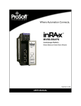
– Tool Compensation (VUE, 200S, 300S)
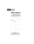
Easy setup with probing functions
A very useful accessory for datum setting
is the HEIDENHAIN KT edge finder: Simply
move the edge finder toward a side of the
workpiece until the stylus deflects. The
counter automatically stores the exact
position, taking into account the direction
of approach and the radius of the stylus. In
milling machine mode, the 200S and 300S
digital readouts offer the following probe
functions:
• Workpiece edge as reference line
• Workpiece centerline as reference line
• Circle center as datum
For electrically conductive workpieces,
these functions are also possible with an
edge finder with contact triggering to
ground.
Convenient datum setting with an edge finder
Datum finding with the tool
The probe functions can also be carried out
with the tool.
Tool compensation for milling machines
The ACU-RITE digital readouts save tool
data in a tool table, i.e. diameter and length
of the tool used. The data can come from
preset tool or be measured on the
machine.
When positioning in distance-to-go mode,
the readouts take the tool radius (R+ or R–)
in the machining plane into account and
consider the tool length (¹L) in the spindle
axis.
Determining and storing tool
compensation values on lathes
You can store the data for the tools you
insert in the turret or quick-change holder in
the tool table:
• Enter the tool position directly when
turning the first diameter, or
• “freeze” the current axis position value,
retract the tool, measure the turned
diameter and then enter that value.
Changing datums
If you change the workpiece or the
workpiece datum, you can fix the new
datum without having to change the stored
tool-offset values. The tool data are
automatically referenced to the new
datum.
6
Compensation of tool radius and length
– Distance-to-Go Display (VUE, 200S, 300S)
– Contour Monitoring (VUE, 300S)
Distance-to-go display for turning
and milling
The distance-to-go display feature
simplifies your work considerably: you
enter the next nominal position, and the
display shows you the distance remaining
to the target position. This means, you
simply traverse to the display value zero.
The displays for milling can also
compensate the cutter radius. In this way
you can directly use the drawing
dimensions without having to do any
conversions. You no longer have to
remember any complicated values.
The distance-to-go display is enhanced by a
“near zero” message: As you traverse to
zero, a square cursor moves into a target
fork. The “near zero” message is
configurable per axis.
300S, VUE:
Contour monitoring for overseeing
manual 2-D operations
Special functions enable you to run 2-D
milling and turning operations with a
manual machine. The contour monitoring
function shows you whether you are
moving the tool near to the defined
contour.
7
Functions
– Hole Patterns (VUE, 200S, 300S)
– Programming of Machining Steps (300S)
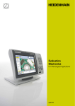
Automatic calculation of bolt hole
patterns for milling and drilling
In milling machine mode you can machine
bolt hole circles (full circle or circle
segments) and linear hole patterns
without having to calculate: You simply
enter the geometric dimensions and the
number of holes from the drawing. The
display calculates the coordinates of the
individual holes in the working plane. You
only need to traverse “to zero” and drill.
Then the display shows the next position.
The graphic display is a particularly useful
feature: it lets you verify your input of the
programmed bolt-hole pattern before
machining.
Programming machining steps
300S programming functions allow you to
save repetitive machining steps. Thus for
example you can save all of the machining
steps required as a program for a
workpiece in a small-batch. In the RUN
mode of operation, the distance-to-go
display will guide you step-by-step to the
programmed positions.
You create programs by typing in the
positions step by step. The fixed cycles
such as Bolt Hole Circle, Linear Hole
Pattern, Incline Mill Form or Circular Arc
keep your programs short and save you
programming time. In the course of your
work, the readout presents each nominal
position in the proper sequence. You need
only move from one position to the next.
8
– Help for Working with Lathes (VUE, 200S, 300S)
Radius/diameter display
In the lathe mode you can see the
positions of the transverse axis in either
radius or diameter values. You can switch at
a keystroke.
Sum display of longitudinal axes
In lathe mode, the positions of the saddle
and the top slide are displayed either
separately or as the sum of both values.
• If you select separate displays, the
position values are referenced to the
datum for each individual axis. If only the
saddle is moved, the displayed value for
the top-slide axis remains unchanged.
• If sum display is selected, the counter
adds both values while taking the
algebraic sign into account. You can now
read the absolute position of the tool in
relation to the workpiece datum—
without having to calculate!
• Vectoring
The vectoring function breaks down the
movement of the compound axis into
the crossfeed or longitudinal axes. If you
are turning threads, for example,
vectoring lets you see the diameter of
the thread in the X-axis display, even
though you are moving the cutting tool
with the compound axis handwheel.
Taper turning made easy
If taper dimensions do not include the
angle, the integrated taper calculator will
help you with the calculation. Simply enter
the taper ratio or the two diameters and
the length. The correct angle for the top
slide will be displayed immediately.
Constant surface speed
Particularly in taper turning or parting, the
surface speed usually changes along with
the diameter. But a constant surface speed
is better for optimum machining results
and long tool life. The 300S and 200S
digital readout in conjunction with the
output module IOB 49 therefore makes it
possible to control workpiece rotation to
ensure a constant surface cutting speed in
spite of a changing workpiece diameter.
Calculation of the taper angle (e.g. 300S)
9
VUE
– Simple Digital Readout for Two or Three Axes
The VUE position displays from ACU-RITE
are suited for use on manually operated
milling, drilling, boring machines and lathes
with two or three axes.
Description
With its sturdy housing and splash-proof
membrane keyboard, the VUE is built for
the workshop. The VUE shows display
position values, the soft-key row and other
useful information on a monochrome
graphic screen.
Functions
The most important functions are available
quickly and directly via function keys. Soft
keys with clear information in the local
language enable you to make entries that
fit your momentary situation.
The distance-to-go display facilitates
positioning. You approach the next position
quickly and reliably by simply traversing
until the display reads “zero”. The functions
for each application are easily activated by
parameter input. Special functions are
available for producing hole patterns
(linear patterns and circular patterns).
You can easily switch between radius and
diameter display when the position display
is configured for turning. For lathes with a
separate top slide, the sum display feature
on the 3-axis version of the VUE allows you
to display the saddle and top slides
together or separately. Setting datums on a
lathe part is particularly easy with the
freeze tool position function and
subsequent retracting.
Data interfaces
A USB interface enables the display unit to
transfer measured values and import or
export parameters and tables.
10
VUE
Axes*
2 or 3 from A to Z and ZO
Encoder inputs
« TTL
Display step1)
Adjustable, max. 7 digits
Linear axis: 1 mm to 0.000 1 mm
Angular axis: 1° to 0.001° (00° 00‘ 01“)
Display
5.7” monochrome flat-panel display for position values, dialogs and inputs, and soft keys
Status display
Tool, reference point, operating function, feed rate, ABS/INC, mm/inch, stopwatch
Functions
•
•
•
•
•
•
•
•
•
•
For milling/drilling/boring
• Calculation of positions for hole patterns (circular patterns as well as linear patterns)
• Tool radius and tool length compensation
• Probing functions for reference-point acquisition with KT edge finder: “Edge”, “Centerline” and
“Circle center”
• Oblique line, circular arc
• Linear hole patterns, bolt hole circles
For turning
•
•
•
•
•
Error compensation
• Axis error: Linear and multipoint over up to 200 points
• Backlash compensation: for compensation of reversal error
Data interface
USB type B connector; up to 115 200 baud
Accessories
Base, mounting arms, mounting frame
Main power input
100 V AC to 240 V AC (–15 % to +10 %), 47 Hz to 63 Hz; 25 W
Operating temperature
0 °C to 45 °C
Protection EN 60 529
IP 40, front panel IP 54
Weight
2.6 kg
10 datums
16 tools
REF reference-mark evaluation for distance-coded or single reference marks
Distance-to-go mode
Scaling factor
mm/inch switching
Absolute-incremental display
On-screen help and operating instructions
Graphic positioning support (Near Zero warning)
Calculator
Taper calculator
Radius/diameter switching
Freezing the tool position for back-off
Vectoring: X/Y display of the traverse path with inclined top slide
Sum displays for Z and ZO (axis coupling)
* Please select when ordering
Depends on the signal period of the connected encoder
1)
11
200S
– Flexible Digital Readout for Two or Three Axes
The ACU-RITE 200S digital readout is
especially suited for use on milling, drilling
and boring machines and lathes with up to
three axes. A separate I/O unit provides
switching input/outputs for simple tasks in
automation.
Description
The 200S display unit is designed as a
sturdy upright unit with splash-proof fulltravel keypad for use in a workshop. It is
equipped with a monochrome flat screen
for position values, dialog and input
displays, graphic functions and graphic
positioning support.
Functions
The 200S display unit is characterized by its
plain language dialog guidance. The
distance-to-go display facilitates
positioning. You approach the next position
quickly and reliably by simply traversing
until the display reads “zero”. The functions
for each application are easily activated by
parameter input. Special functions are
available for producing hole patterns
(linear patterns and circular patterns).
Datums can be determined quickly and
accurately with an edge finder. The 200S
readout supports you with special probing
functions.
You can easily switch between radius and
diameter display when the position display
is configured for turning. The readout also
offers support for lathes with separate top
slide: The sum display feature allows you
to display the saddle and top slides
together or separately. To set a datum,
touch the workpiece and freeze the tool
position. Then retract and measure the
workpiece.
Data interfaces
The 200S features an RS-232-C/V.24 serial
interface for measured value transfer to a
PC or printer, for input/output of parameters
and compensation value lists, and for
diagnostics.
12
200S
Axes*
2 or 3 from A to Z and ZO
Encoder inputs
« TTL
Display step1)
Adjustable, max. 7 digits
Linear axis: 1 mm to 0.000 1 mm
Angular axis: 1° to 0.001° (00° 00‘ 01“)
Display
5.7” monochrome flat-panel display for position values, dialogs and inputs, and soft keys
Status display
Tool, reference point, operating function, feed rate, ABS/INC, mm/inch, stopwatch
Functions
•
•
•
•
•
•
•
•
•
•
For milling/drilling/boring
• Calculation of positions for hole patterns (circular patterns as well as linear patterns)
• Tool radius and tool length compensation
• Probing functions for reference-point acquisition with KT edge finder: "Edge," "Centerline" and "Circle
center"
• Linear hole patterns, bolt hole circles
For turning
•
•
•
•
•
Error compensation
• Axis error: Linear and multipoint over up to 200 points
• Backlash compensation: for compensation of reversal error
Data interface
RS-232-C/V.24 300 to 115 200 baud
Switching I/O
• Input for edge finder (with switching signal or contact triggering)
• Further inputs/outputs over the IOB 49 external input/output unit
Accessories
Mounting arms, mounting frame, KT 130 edge finder (for milling)
Main power input
100 V AC to 240 V AC (–15 % to +10 %), 47 Hz to 63 Hz; 30 W
Operating temperature
0 °C to 45 °C
Protection EN 60 529
IP 40, front panel IP 54
Weight
2.6 kg
10 datums
16 tools
REF reference-mark evaluation for distance-coded or single reference marks
Distance-to-go mode
Scaling factor
mm/inch switching
Absolute-incremental display
On-screen help and operating instructions
Graphic positioning support (Near Zero warning)
Calculator
Taper calculator
Radius/diameter switching
Freezing the tool position for back-off
Vectoring: X/Y display of the traverse path with inclined top slide
Sum displays for Z and ZO (axis coupling)
* Please select when ordering
Depends on the signal period of the connected encoder
1)
13
300S
– Programmable Digital Readout for up to 4 Axes
The 300S digital readout from ACU-RITE is
a versatile display unit designed primarily
for milling machines, drilling and boring
machines and lathes with up to 4 axes. A
separate I/O unit provides switching input/
outputs for simple tasks in automation.
Description
The 3000S display unit is designed as a
sturdy upright unit with splash-proof fulltravel keypad for use in the workshop. It
supports all operations with straightforward
interactive menus on its large, easy-to-read
color flat screen.
Functions
The 300S digital readout offers all the
functions of the 200S.
In addition, the 300S is programmable,
which makes it ideal for small-batch
production on conventional machine tools:
you can store up to 8 programs in the
300S, each with up to 250 working steps.
Programs are created by either keying
them in step by step or generating them
through actual position capture (teach-in
programming).
Data interfaces
The 300S features an RS-232-C/V.24 serial
interface for measured value transfer to a
PC or printer, for input/output of parameters
and compensation value lists.
14
300S
Axes
4 from A to Z and ZO
Encoder inputs
« TTL
Display step1)
Adjustable, max. 7 digits
Linear axis: 1 mm to 0.000 1 mm
Angular axis: 1° to 0.001° (00° 00‘ 01“)
Display
5.7” color flat-panel display for position values, dialogs and inputs, and soft keys
Status display
Tool, reference point, operating function, feed rate, ABS/INC, mm/inch, stopwatch
Axis display
Switchable between DRO1 and DRO2
Functions
•
•
•
•
•
•
•
•
•
•
For milling/drilling/boring
• Calculation of positions for hole patterns (circular patterns as well as linear patterns)
• Tool radius and tool length compensation
• Probing functions for reference-point acquisition with KT edge finder: “Edge”, “Centerline” and
“Circle center”
• Oblique line, circular arc
• Linear hole patterns, bolt hole circles
For turning
•
•
•
•
•
Programming modes
8 programs with up to 250 steps
Error compensation
• Axis error: Linear and multipoint over up to 200 points
• Backlash compensation: for compensation of reversal error
Data interface
RS-232-C/V.24 300 to 115 200 baud
Switching I/O
• Input for edge finder (with switching signal or contact triggering)
• Further inputs/outputs over the IOB 49 external input/output unit
Accessories
Mounting arms, mounting frame, KT 130 edge finder (for milling)
Main power input
100 V AC to 240 V AC (–15 % to +10 %), 47 Hz to 63 Hz; 30 W
Operating temperature
0 °C to 45 °C
Protection EN 60 529
IP 40, front panel IP 54
Weight
2.6 kg
10 datums
99 tools
REF reference-mark evaluation for distance-coded or single reference marks
Distance-to-go mode
Scaling factor
mm/inch switching
Absolute-incremental display
On-screen help and operating instructions
Graphic positioning support (Near Zero warning)
Calculator
Taper calculator
Radius/diameter switching
Freezing the tool position for back-off
Vectoring: X/Y display of the traverse path with inclined top slide
Sum displays for Z and ZO (axis coupling)
* Please select when ordering
Depends on the signal period of the connected encoder
1)
15
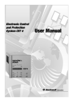
Accessories
– Edge Finder
KT 130 edge finder
For any workpiece materials
With spiral cable
ID 283 273-S1
The KT 130 is a 3-D triggering edge finder.
This means it can also be used for
nonconducting materials. The stylus is
deflected when it contacts the workpiece,
and the edge finder sends a triggering
signal over the connecting cable to the
200S or 300S digital readout.
The KT 130 edge finder allows you to set
reference points quickly and easily, without
leaving marks on the workpiece.
16
– Mounting Components
The 200S and 300S digital readouts were
conceived as upright units. There are several
possible mounting configurations:
• Threaded mounting holes M6 and M8 on
the housing floor
• Mounting frame
• Mounting arm and tilt/swivel assembly
m Cutout for mounting
Accessory:
Mounting arms (see page 18)
Accessories (accessory)
ID 532 811-01
For mounting the digital readout in a
housing or operating panel
The VUE digital readout is fastened either
on a mounting arm on the machine, with
the aid of a mounting base, or installed
in a control panel. The parts required for
fastening the display are included in
delivery.
They enable you to rotate and tilt the
display. The mounting arm and base are
available as accessories:
Accessory:
Mounting arms (see page 18)
Mounting base
ID 625 491-01
Mounting frame
ID 647 702-01
For mounting the VUE in a housing or
operating panel
m Cutout for
mounting
17
Accessories
– Mounting Components
You can use the mounting arm to easily
place the display at a conveniently operable
position. It can be attached to the machine
either with a mounting bracket or directly.
The display is attached to the mounting
arm by its own tilt/swivel mount.
Mounting arm A
Accessory for VUE, 200S, 300S
Short version: 300 mm
ID 683 663-01
Long version: 670 mm
ID 683 670-01
Mounting arm B
Accessory for VUE, 200S, 300S
ID 683 665-01
Mounting arm C
Accessory for VUE, 200S, 300S
ID 683 671-01
18
Mounting arm D
Accessory for VUE, 200S, 300S
ID 683 668-01
Consists of
683 663-01,
683 673-01 and
683 674-01
Parts
a) U-section with tilt/swivel assembly
Fits mounting arms A and B
ID 683 669-01
b) Extension
Fits mounting arms A and B
ID 683 673-01
c) Mounting bracket
Fits mounting arms A and B
ID 683 674-01
Mounting arm E
Accessory for 200S, 300S
ID 683 672-01
The digital readout can be locked in various
positions over two ball joints.
Overall height approx. 210 mm
19
Accessories
– IOB 49 External Input/Output Unit for 200S/300S
The 200S/300S provide applicationdependent additional functions that are
available when the IOB 49 external input/
output unit is connected.
IOB 49 external input/output unit
ID 532 900-01
The IOB 49 input/output unit is attached to
a standard NS 35 rail (DIN 46 227 or
EN 50 022).
It is connected to the 200S/300S using the
touch probe input. LEDs show the power
supply, the data transmission and the
status of the inputs and outputs.
Accessory:
Connecting cable complete with
connector, between IOB 49 and
200S/300S
ID 532 899-xx
IOB 49
4 switching inputs
Zero reset of axes 1 to 3 (for milling applications)
Recognition of max. 3 operating gears (for turning applications)
External activation of CSS (for turning applications)
9 switching outputs
8 relay outputs as switching functions (for milling applications)
1 relay output for readiness
1 analog output
0 to 10 V
Turning mode: For constant surface speed
Milling mode: For controlling the spindle speed
Power supply
Via 200S/300S
Cable length
† 15 m to 200S/300S
Storage temperature
20 °C to 70 °C
Operating temperature 0 °C to 45 °C
Distribution cable complete with
connectors, for parallel connection of
IOB 49 and KT 130 to 200S/300S
ID 532 909-01
The additional functions can be configured
on the 200S/300S when the IOB 49 is
connected.
Switching inputs
The switching inputs are active when a
High signal (contact or pulse) is present.
They are isolated and can be supplied
externally or internally.
Signal level of the switching outputs
0 V † UL † 1.5 V
4.5 V † UH † 26 V
IL † 25 mA
tmin ‡ 100 ms
Zero reset
In the milling mode, each axis can be set to
the display value 0 over an external signal.
Detection of gear ranges
In the turning mode, three switching inputs
are available for the recognition of gear
ranges.
20
Switching inputs for
internal power supply
Switching inputs for
external power supply
Switching outputs
The IOB 49 features nine floating relay
outputs.
X103
Readiness
The readiness output is at LOW level if the
200S/300S cannot operate the IOB (e.g.
not switched on, cable disconnected).
Switching functions (milling mode)
One or more switching ranges or switching
points can be defined for an axis. Switchoff ranges lie symmetrically to the 0
display value. If switching points are
used, the relay activates when the position
display reaches a specific value. The
direction function switches when the
algebraic sign is changed.
You can set whether
• the switching function should apply to
the actual value or distance-to-go mode
• the relay will open or close when the
condition is met
• or the relay remains activated as
long as the switching condition is met
(continuous mode) or for a specified
duration (pulsed mode).
Switch-off range (e.g.)
Switching point (e.g.)
Direction (e.g.)
Condition
Analog output
Constant surface cutting speed CSS
(only in turning applications)
CSS provides spindle speed control as the
diameter of the workpiece changes. A
speed command signal is sent to the
inverter of the spindle motor via the analog
interface (DAC 0 V to 10 V) of the IOB 49.
The maximum and minimum permissible
spindle speeds can be specified. In
addition, a maximum of three operating
gears can be taken into account. The
200S/300S recognize the current gear
selection by means of the switching inputs
of the IOB 49. CSS control can also be
started remotely (via an input to the CSS
board) with an external switch.
Relay in
continuous mode
Relay in pulsed
mode
X102
Controlling the spindle speed
(only in milling applications)
With the analog outputs, the speed of the
spindle on milling machines can be
controlled in an open controlled loop. A
spindle speed can be assigned to each tool
defined in the tool table. The speed can be
manually adapted during machining.
21
Interfaces
– Digital Readouts
Pin layout of encoders « TTL
Mating connector:
9-pin D-sub connector (male)
Power supply
« TTL
Incremental signals
7
6
2
UP
0V
Ua1
3
Others
4
5
8
9
1
Ua2
£
Ua0
¤
/
Shield on housing; UP = Power supply voltage
KT 130 edge finder
(only 200S, 300S)
Pin
Assignment
A 15-pin D-sub connection is provided for
the KT 130 edge finder.
6
5V
1
0 V (internal shield)
8
0V
2
Readiness
13
Trigger signal
Remaining pins
Do not assign
Housing
External shield
The trigger signal of the edge finder can
also start data output (adjustable by
parameter).
Edge finder with contact
triggering (only 200S, 300S)
Edge finders that operate according to the
contacting principle can be connected
through a 3.5 mm phone jack.
200S/300S
or
22
RS-232-C/V.24 (only 200S, 300S)
This serial interface follows the EIA
standard RS-232-C and the CCITT standard
V.24. It uses a 9-pin D-sub female
connection. The data are transferred in
ASCII code. The data format is adjustable.
Accessories
Connecting cable, complete with two
D-sub connectors (female) 9-pin
ID 366 964-xx
Connecting cable, complete with
connectors
With D-sub connector (female) 9-pin and
25-pin (male)
ID 368 017-xx
USB (only VUE)
The VUE digital readout has a USB
interface function with connector type B.
The USB interface functions as a UART
(Universal Asynchronous Receiver
Transmitter). A special driver software is
required for operation (free download at
www.heidenhain.de). The data are
transferred in ASCII code.
Pin
Assignment
1
Do not assign
3
TXD
– Transmitted data
2
RXD
– Received data
7
RTS
– Request to send
8
CTS
– Clear to send
6
DSR
– Data set ready
5
SIGNAL GND
– Signal ground
4
DTR
– Data terminal ready
9
Do not assign
Signal
Signal levels
1 = active
Signal levels
0 = not active
TXD, RXD
–3 V to –15 V
+3 V to +15 V
RTS, CTS
DSR, DTR
+3 V to +15 V
–3 V to –15 V
Pin
Assignment
1
VCC
+ 5V
2
D–
Data –
3
D+
Data +
4
GND
Weight
23
Linear Encoders
– for Manually Operated Machine Tools
For typical applications on manual machine
tools such as milling machines or lathes,
display steps of 10 µm are sufficient.
This is provided by the linear encoder of
the SENC 50 and SENC 150 series without
interpolation.
Jig boring machines, grinding machines,
and measuring and inspection tasks
normally require display steps of 1 µm
and better. The SENC 50 and SENC 150
with integral 5-fold or 10-fold interpolation
are suitable for these higher requirements.
For limited installation space, for
example on the slide of a lathe, the SENC
50 linear encoder may be the best solution.
The SENC 150 linear encoders are used as
universal linear encoders under normal
mounting conditions.
24
Mounting Information
SENC 50
This linear encoder with small cross
section is fastened at points on a machined
surface. With a back-up spar, only two
points, one at each end, are sufficient.
For mounting without back-up spar, an
intermediate support is required in addition.
The encoder is mounted so that the sealing
lips are directed downward or away from
splashwater.
Mounting
When mounting, the scale unit must be
aligned at several points along the machine
guideway. Stop surfaces or stop pins can
also be used to align the scale.
The proper gap between the scale housing
and scanning unit is ensured by the
shipping brace. You must also ensure that
the lateral tolerance is maintained.
Accessory
Back-up spar for SENC 50
ID 680 803-xx
The SENC 50 can be mounted on a back-up
spar to increase stability.
SENC 150
The SENC 150 is fastened at its ends by
their mounting blocks to a machined
surface. A support bracket is provided for
measuring lengths above 625 mm.
If the SENC 150 is mounted with a back-up
spar, there is no need for the support
bracket. At measuring lengths of 1675 mm
or more, the back-up spar is essential. The
encoder is mounted so that the sealing lips
are directed downward or away from
splashwater.
Mounting
When the SENC 150 is mounted, the
shipping brace already ensures the proper
gap between the scale unit and the
scanning unit. You need only align the scale
unit at several points along the machine
guideway.
Accessory
Back-up spar for SENC 150
ID 680 116-xx
The SENC 150 can be mounted on a backup spar to increase stability. At measuring
lengths of 1675 mm or more, the back-up
spar is essential and is already included in
delivery.
25
SENC 50
Incremental linear encoder
• Extremely compact dimensions
• Measuring steps 5 µm to 0.5 µm
Â
ML = Measuring length
P = Gauging points for alignment
s = Beginning of measuring length
k = Required mating dimensions
À = M4 nut usable
Á = For aligning the back-up spar
 = Direction of scanning head motion for
output signals in accordance with interface
description
26
ML (mm)
50
75
100
125
150
175
200
225
250
275
300
325
350
375
425
475
525
LL (inch)
1
2
3
4
5
6
7
8
9
10
11
12
13
14
16
18
20
L
143.5/5.65“
168.9/6.65“
194.3/7.65“
219.7/8.65“
245.1/9.65“
270.5/10.65“
295.9/11.65“
321.3/12.65“
346.7/13.65“
372.1/14.65“
397.5/15.65“
422.9/16.65“
448.3/17.65“
473.7/18.65“
524.5/20.65“
575.3/22.65“
626.1/24.65“
L1
20.96/0.825“
20.96/0.825“
33.66/1.325“
46.36/1.825“
59.06/2.325“
71.76/2.825“
84.46/3.325“
97.16/3.825“
46.36/1.825“
59.06/2.325“
71.76/2.825“
84.46/3.325“
97.16/3.825“
46.36/1.825“
71.76/2.825“
33.66/1.325“
59.06/2.325“
L2
101.6/4“
127.0/5“
127.0/5“
127.0/5“
127.0/5“
127.0/5“
127.0/5“
127.0/5“
127.0/5“
127.0/5“
127.0/5“
127.0/5“
127.0/5“
127.0/5“
127.0/5“
254.0/10“
254.0/10“
Qty. B
2x
2x
2x
2x
2x
2x
2x
2x
3x
3x
3x
3x
3x
4x
4x
3x
3x
Specifications
SENC 50
Measuring standard
Glass scale with incremental graduation
Accuracy grade
± 3 µm
Measuring length ML*
Back-up spar* optional
50
75 100 125
475 525
150
175
200
225
250
275
300
325
350
Incremental signals*
« TTL
« TTL x 5
« TTL x 10
Grating period
Integrated interpolation
Signal period
20 µm
None
20 µm
20 µm
5-fold
4 µm
20 µm
10-fold
2 µm
Measuring step1)
5 µm
1 µm
0.5 µm
Reference marks
Distance-coded
Power supply
Without load
5.1 V DC ± 0.1 V/< 180 mA
Electrical connection
Cable in metal armor, with 9-pin D-sub connector; length: 3 m
Cable length
† 6 m (total length with ACU-RITE cable)
Traversing speed
† 60 m/min
Required moving force
† 2.2 N
Operating conditions
Temperature 0 °C to 50 °C; humidity 25 % to 95 % (non-condensing)
Conditions for storage
Temperature –20 °C to 70 °C; humidity 20 % to 95 % (non-condensing)
Protection EN 60 529
IP 53 when mounted according to the instructions
Weight
0.5 kg + 0.3 kg/m measuring length
* Please indicate when ordering
1)
375
425
5.1 V DC ± 0.1 V/< 220 mA
Depending on the subsequent electronics
27
SENC 150
Incremental linear encoder
• Sturdy design
• Measuring lengths up to 3 m
• Measuring steps 5 µm to 0.5 µm
À = For ML ‡ 625 mm/24 inches to † 1550 mm/
60 inches use mid-point fastening
ML = Measuring length
P = Gauging points for alignment
s = Beginning of measuring length
k = Required mating dimensions
ML (mm) LL (inch) L
75
2
211.12/8.31"
100
3
236.52/9.31"
125
4
261.92/10.31"
150
5
287.32/11.31"
175
6
312.72/12.31"
225
8
363.52/14.31"
275
10
414.32/14.31"
300
11
439.72/17.31"
325
12
465.12/18.31"
350
13
490.50/19.31"
375
14
515.92/20.31"
400
15
541.32/21.31"
425
16
566.72/22.31"
475
18
617.52/24.31"
525
20
668.32/26.31"
625
24
769.92/30.31"
675
26
820.72/32.31"
725
28
871.52/34.31"
775
30
922.32/36.31"
28
L1
42.06/1.656"
54.76/2.156"
67.46/2.656"
80.16/3.156"
29.36/1.156"
54.76/2.156"
80.16/3.156"
92.86/3.656"
105.56/4.156"
36.60/1.441"
130.96/5.156"
16.66/ .656"
29.36/1.156"
54.76/2.156"
80.16/3.156"
130.96/5.156"
29.36/1.156"
54.76/2.156"
80.16/3.156"
L2
127.0/5"
127.0/5"
127.0/5"
127.0/5"
254.0/10"
254.0/10"
254.0/10"
254.0/10"
254.0/10"
417.3/16.43"
254.0/10"
254.0/10"
254.0/10"
254.0/10"
254.0/10"
254.0/10"
254.0/10"
254.0/10"
254.0/10"
Qty. B
2x
2x
2x
2x
2x
2x
2x
2x
2x
2x
2x
3x
3x
3x
3x
3x
4x
4x
4x
ML (mm)
825
875
925
950
1000
1050
1100
1250
1350
1400
1550
1675
1850
2000
2150
2300
2575
2825
3075
LL (inch)
32
33
35
36
38
40
42
48
52
54
60
65
72
78
84
90
100
110
120
Á = Direction of scanning head motion for
output signals in accordance with interface
description
L
906.45/35.69"
998.52/39.31"
1049.27/41.31"
1074.72/42.31"
1125.52/44.31"
1176.32/46.31"
1227.12/48.31"
1379.52/54.31"
1481.12/58.31"
1531.92/60.31"
1684.32/66.31"
1811.26/71.31"
1989.12/78.31"
2141.52/84.31"
2293.92/90.31"
2446.32/96.31"
2700.32/106.31"
2954.32/116.31"
3208.32/126.31"
L1
11.10/ .437"
118.26/4.656"
11.10/ .437"
29.36/1.156"
54.76/2.156"
80.16/3.156"
105.56/4.156"
54.76/2.156"
105.56/4.156"
130.96/5.156"
80.16/3.156"
143.66/5.656"
105.56/4.156"
54.76/2.156"
130.96/5.156"
80.16/3.156"
80.16/3.156"
80.16/3.156"
80.16/3.156"
L2
294.7/11.604"
254.0/10"
256.8/10.109"
254.0/10"
254.0/10"
254.0/10"
254.0/10"
254.0/10"
254.0/10"
254.0/10"
254.0/10"
254.0/10"
254.0/10"
254.0/10"
254.0/10"
254.0/10"
254.0/10"
254.0/10"
254.0/10"
Qty. B
4x
4x
5x
5x
5x
5x
5x
6x
6x
6x
7x
7x
8x
9x
9x
10x
11x
12x
13x
SENC 150
Measuring standard
Glass scale with incremental graduation
Accuracy grade
± 5 µm
Measuring length ML*
Back-up spar* optional
75 100 125 150
625 675 725 775
175
825
225
875
275
925
300
950
325 350 375 400 425 475 525
1 000 1 050 1 100 1 250 1 350 1 400 1 550
Back-up spar included in items supplied
1 675 1 850 2 000 2 150 2 300 2 575 2 825 3 075
Incremental signals*
« TTL
« TTL x 5
« TTL x 10
Grating period
Integrated interpolation
Signal period
20 µm
None
20 µm
20 µm
5-fold
4 µm
20 µm
10-fold
2 µm
Measuring step1)
5 µm
1 µm
0.5 µm
Reference marks
Distance-coded
Power supply
Without load
5.1 V DC ± 0.1 V/< 180 mA
Electrical connection
Cable in metal armor, with 9-pin D-sub connector; length: 4 m
1250 mm measuring length or more: length 6 m
Cable length
† 9 m (total length with ACU-RITE cable)
Traversing speed
† 60 m/min
Required moving force
† 3.4 N
Operating conditions
Temperature 0 °C to 50 °C; humidity 25 % to 95 % (non-condensing)
Conditions for storage
Temperature –20 °C to 70 °C; humidity 20 % to 95 % (non-condensing)
Protection EN 60 529
IP 53 when mounted according to the instructions
IP 64 with compressed air inlet
Weight
0.65 kg + 0.7 kg/m measuring length
* Please indicate when ordering
1)
5.1 V DC ± 0.1 V/< 220 mA
Depending on the subsequent electronics
29
Interfaces
Incremental Signals « TTL
ACU-RITE encoders with « TTL
interface incorporate electronics that
digitize sinusoidal scanning signals
with or without interpolation.
Interface
Square-wave signals « TTL
Incremental signals
2 square-wave signals Ua1, Ua2 and their inverted signals
,£
The incremental signals are transmitted
as the square-wave pulse trains Ua1 and
Ua2, phase-shifted by 90° elec. The
reference mark signal consists of one or
more reference pulses Ua0, which are
gated with the incremental signals. In
addition, the integrated electronics produce
their inverse signals
and £ for noiseproof transmission. The illustrated
sequence of output signals—with Ua2
lagging Ua1—applies to the direction of
motion shown in the dimension drawing.
Reference-mark
signal
1 or more square-wave pulses Ua0 and their inverted
pulses ¤
Pulse width
90° elec.
Signal levels
Differential line driver as per EIA standard RS-422
UH ‡ 2.5 V at –IH = 20 mA
UL † 0.5 V at IL = 20 mA
Signal period 360° elec.
The distance between two successive
edges of the incremental signals Ua1 and
Ua2 through 1-fold, 2-fold or 4-fold
evaluation is one measuring step. The
subsequent electronics must be designed
to detect each edge of the square-wave
pulse.
Measuring step after
4-fold evaluation
9-pin D-sub connector
On linear encoder or
mating connector to digital readout
Power supply
PIN
Incremental signals
7
6
2
UP (VCC)
0V
Ua1 (A+)
SENC 50
Black
White
Green
SENC 150
Brown
White
Green
Signal
Shield on housing; UP = Power supply voltage
Vacant pins or wires must not be used.
Color assignment applies only to cable.
30
3
4
5
9
8
1
Ua2 (B+)
£ (B–)
Ua0 (R–)
¤ (R+)
/
Yellow
Pink
Red
Brown
Gray
/
Yellow
Blue
Red
Gray
Pink
/
(A–)
Electrical Connection
Cables
Extension cables for SENC
ACU-RITE linear encoders feature cables
with D-sub connector for direct connection
to ACU-RITE digital readouts. The exact
length of the cable can be found in the
Specifications. If the cable length is
insufficient, extension cables are offered
complete with connectors.
Upon request you can also order adapter
cables for connection to discontinued
ACU-RITE products.
Extension cables
Length
In metal armor
Without metal armor
Complete with D-sub
connectors (female and male)
1.5 m
3.0 m
4.5 m
6.0 m
7.5 m
683 276-05
683 276-10
683 276-15
683 276-20
683 276-25
683 277-05
683 277-10
683 277-15
683 277-20
683 277-25
General Electrical Information
Transmission of measuring signals—
electrical noise immunity
Noise voltages arise mainly through
capacitive or inductive transfer. Electrical
noise can be introduced into the system
over signal lines and input or output
terminals.
Possible sources of noise include:
• Strong magnetic fields from
transformers, brakes and electric motors
• Relays, contactors and solenoid valves
• High-frequency equipment, pulse
devices, and stray magnetic fields from
switch-mode power supplies
• AC power lines and supply lines to the
above devices
Protection against electrical noise
The following measures must be taken to
ensure disturbance-free operation:
• Use only original ACU-RITE cables.
Consider the voltage attenuation on
supply lines.
• Use connecting elements (such as
connectors or terminal boxes) with metal
housings. Only the signals and power
supply of the connected encoder may
be routed through these elements.
Applications in which additional signals
•
•
•
•
are sent through the connecting element
require specific measures regarding
electrical safety and EMC.
Connect the housings of the encoder,
connecting elements and subsequent
electronics through the shield of
the cable. Ensure that the shield has
complete contact over the entire surface
(360°). For encoders with more than one
electrical connection, refer to the
documentation for the respective
product.
For cables with multiple shields, the inner
shields must be routed separately from
the outer shield. Connect the inner shield
to 0 V of the subsequent electronics. Do
not connect the inner shields with the
outer shield, neither in the encoder nor
in the cable.
Connect the shield to protective ground
as per the mounting instructions.
Prevent contact of the shield (e.g.
connector housing) with other metal
surfaces. Pay attention to this when
installing cables.
• Do not install signal cables in the direct
vicinity of interference sources (inductive
consumers such as contactors, motors,
frequency inverters, solenoids, etc.).
– Sufficient decoupling from
interference-signal-conducting cables
can usually be achieved by an air
clearance of 100 mm or, when cables
are in metal ducts, by a grounded
partition.
– A minimum spacing of 200 mm to
inductors in switch-mode power
supplies is required.
• If compensating currents are to be
expected within the overall system, a
separate equipotential bonding
conductor must be provided. The shield
does not have the function of an
equipotential bonding conductor.
• Provide power only from PELV systems
(EN 50 178) to position encoders.
Provide high-frequency grounding with
low impedance (EN 60 204-1 Chap.
EMC).
31
DR. JOHANNES HEIDENHAIN GmbH
Dr.-Johannes-Heidenhain-Straße 5
83301 Traunreut, Germany
{ +49 8669 31-0
| +49 8669 5061
E-mail: [email protected]
www.acu-rite.de
United Kingdom
HEIDENHAIN (G.B.) Limited
200 London Road, Burgess Hill
West Sussex RH15 9RD, United Kingdom
{ +44 1444 247711
| +44 1444 870024
www.heidenhain.co.uk
France
HEIDENHAIN FRANCE sarl
2 avenue de la Cristallerie
92310 Sèvres, France
{ +33 0141143000
| +33 0141143030
www.heidenhain.fr
North America
HEIDENHAIN CORPORATION
333 East State Parkway
Schaumburg, IL 60173-5337, USA
{ +1 847 490-1191
| +1 847 490-3931
www.acu-rite.com
732 646-21 · 10 · 9/2011 · F&W · Printed in Germany
Zum Abheften hier falzen! / Fold here for filing!
Sales and Service—Worldwide