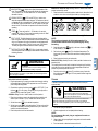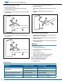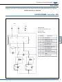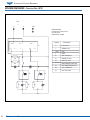
1
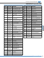
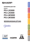
English Operator’s Manual Countertop Convection Oven Item Model Description 40703 40701 40702 COA7002 COA8004 COA8005 Half-size Half-size Full-size Shelves (Included) 3 4 4 Watts Amps Voltage Plug 1,500 2,520 5,600 12.5 11 25.5 120 230 230 5-15P 6-15P 6-50P Thank you for purchasing this Vollrath Counter Top Cooking Equipment. Before operating the equipment, read and familiarize yourself with the following operating and safety instructions. SAVE THESE INSTRUCTIONS FOR FUTURE REFERENCE. Save the original box and packaging. Use this packaging to ship the equipment if repairs are needed. Item No. 2350085-1 en Rev 02/14 Countertop Cooking Equipment Safety Precautions Function and Purpose To ensure safe operation, read the following statements and understand their meaning. Please read carefully. This unit is intended to be used for cooking fresh or frozen foods in a commercial foodservice operations only. It is not intended for household, industrial or laboratory use. Before using this equipment it must be cleaned and dried thoroughly. Clean all surfaces before use. Failure to clean surfaces before using the unit could cause food contamination. This equipment is a medium duty appliance capable of a wide variety of bake applications. The temperature is thermostatically controlled. The temperature range is 150°F - 570°F (65°C - 299°C). Controls l °F l l l l 0 40 l l 3 5 0 0 10 l l l 20 l N O l 0 l 0 4 l 0 0 l l l l l l 0 400 350 30 l 5 D l l l l l l 250 200 150 l 1 Figure 1. 40703 and 40701 Controls. A C l l 550 50 l l 0 l l 0 l 0 0 l l l l l l 250 200 150 l 1 D Figure 2. 40702 Controls. l l l l 0 40 l l 3 5 20 0 D l l l l l l 0 l 60 7 80 9 l Operator’s Manual l D 4 2 550 50 l l 0 l l l l l l 0 400 350 30 l 5 0 To reduce risk of injury or damage to the equipment: Do not set items on door, use the door as a shelf or lean on door. Use only grounded electrical outlets matching the nameplate rated voltage. Do not use an extension cord with this equipment. Do not plug this equipment into a power strip or multi-outlet power cord. Unplug equipment, turn off and let it cool before cleaning or moving. Keep equipment and power cord away from open flames, electric burners or excessive heat. Do not operate equipment in public areas and/or around children. The equipment may be hot, even though the pilot light(s) is not on. Do not operate if equipment has been damaged or is malfunctioning in any way. Do not clean the equipment with steel wool. D C l l l l 550 50 l l 0 4 These precautions should be followed at all times. Failure to follow these precautions could result in injury to yourself and others. B l l l l l l 0 400 350 30 l 5 0 For Your Safety! A E l l l l l l 0 l 60 7 80 9 l Fire Hazard and Burn Hazard. Injuries or death can occur if this equipment is not used properly. To reduce risk of injury or death: • Unit should only be used in a flat, level position. • Let hot unit cool before cleaning or moving. • Do not spray controls or outside of unit with liquids or cleaning agents. • Do not operate unattended. l 0 0 WARNING l Fire Hazard. This unit is designed to be used with legs. Do not use without legs installed. Use of this equipment without legs can cause the unit to over heat and cause a fire. 10 WARNING l l l Fire Hazard. Have this equipment installed by a qualified installer in accordance with all Federal, State and Local Codes. Failure to install this equipment properly can result in injury or death. 0 WARNING l N O Note is used to notify people of installation, operation, or maintenance information that is important but not hazard-related. When no longer needed, dispose of all packaging and materials in an environmentally responsible manner. 1. Remove all packing material and tape, as well as any protective plastic from the equipment. 2. Clean any glue residue left over from the plastic or tape. NOTE: There must be a minimum of 12” (30.4 cm) between the equipment and any surrounding walls. The surrounding walls must be made of noncombustible materials. The equipment must be installed in accordance with local fire and building regulations. 3. Place the equipment in the desired position and height. 4. Model 40702 Only. This model is equipped with a water spray feature. To utilize the water spray feature the unit should be connected to a potable water supply with a pressure between 3 and 30 PSI. The 4” legs must be installed to comply with NSF. 5. Plug the equipment into a properly grounded electrical supply matching the nameplate rating. Damage to the equipment can occur if incorrect power is supplied to equipment. l l l l 100 120 NOTE Unpacking the Equipment and Initial Setup 0 Caution is used to indicate the presence of a hazard that will or can cause minor personal injury or property damage if the caution is ignored. l l l l l l 250 200 150 l 1 0 CAUTION l l l l 100 120 Warning is used to indicate the presence of a hazard that can cause severe personal injury, death, or substantial property damage if the warning is ignored. 0 WARNING Countertop Cooking Equipment E MIST CONTROL BUTTON (40702 Only). A push button located on the front panel of the oven. Sprays a small amount of water to enter the baking chamber. Operation Burn Hazard. Do not touch hot food, liquid or heating surfaces while equipment is heating or operating. Hot surfaces and food can burn skin. Allow the hot surfaces to cool before handling. Do not drop or spill water onto the cooking surface as it can spray or splatter. Before initial use burn-in procedure: 1. Plug the equipment into a properly grounded electrical supply matching the nameplate rating. Damage to the equipment can occur if incorrect power is supplied to equipment. 2. Close the door and turn the bake control (A) to 525°F (274°C). set the timer (C) for 30 minutes. During this burn-in you may notice a slight odor, this is normal. See Figures 1 and 2. All Models: Baking Function - Used to bake or cook food product. 1. Place the wire shelves or pans in the desired positions inside the unit. Allow a space of at least 2” (5 cm) between wire shelves or pans. 2. Set the bake control (A) the desired temperature. 3. Set the timer control (C) to the desired time. The fan and oven light will operate continuously. The heating elements will cycle on and off to maintain a consistent temperature. 4. Place food product into the unit and monitor. l l l l l 0 40 l l 3 5 0 0 10 l l l 20 l N O °F l 0 l 0 0 0 l l C Figure 3. 40703 and 40701 Controls set for the Browning Function. NOTE: The fans do not operate in the browning mode. It is recommended that the door be opened slightly during browning. 2. Switch the bake control knob (A) to the brown function icon to the indicator (C). See Figure 3. (B) 3. Set the brown control knob (D) to the desired temperature. The timer control (E) does not need to be used for the browning function to operate. 4. Place food product into the unit and monitor. Models 40702 Only: Humidity Function - Used to provide a heavier crust on bread and rolls. The humidity function works best if activated at the beginning of the baking cycle after the oven has reached the cooking temperature and the food product has just been placed into the oven. English WARNING l l l l l 0 150 100 0 PILOT LIGHTS. This light indicates that the oven is heating and the timer is activated. Once the set temperature has been reached the light will go out. Equipment will continue to maintain heat and temperature as the light cycles on and off. This light is not a power “ON” indicator. The timer pilot light will illuminate when the timer is operating. l l l l l l 250 200 150 l 1 0 D 550 50 l l 0 00 l l l l 100 120 TIMER . Timer can be set for 1 - 120 minutes, or it can set to constant “ON” position. The timer must be operating in order for “Bake” to function. The timer has no bell or buzzer. l l l l00 l 45l0 l l 5 4 0 C l 0 55 E D A B l l l l l l 0 l 60 7 80 9 l BROWN CONTROL (40701 and 40702 Only). Used to set or adjust the temperature of the upper element. The numbers on the dial correspond with the oven temperature. The bake control must be set in the “BROWN” position and the timer in the “ON” position for the upper element to heat. The fan does not operate when the brown function is operating. 4 B Models 40701 and 40703 Only: Browning Function - Used to brown a food product has been fully cooked. 1. Place the shelves in the desired positions inside the unit. Assure the food product is not too close or touching the inside top or heating element. l l l l l l 0 400 350 30 l 5 BAKE CONTROL . Used to set or adjust the temperature of the oven. The numbers on the dial correspond with the oven temperature. The “0” position is off. The timer needs to be “ON” for the heating elements to function. l l l l 300 25l0 l l 350 2 A button (E) to activate a spray of water into 1. Press the mist control the cooking chamber. See Figure 2. Do not press the button longer than 2-second pulses. Cleaning To maintain the appearance and increase the service life, clean your equipment daily. WARNING Electrical Shock Hazard. Keep water and other liquids from entering the inside of the equipment. Liquid inside the equipment could cause an electrical shock. Do not spray water or cleaning products. Liquid could contact the electrical components and cause a short circuit or an electrical shock. Do not use equipment if power cord is damaged or has been modified 1. Turn off and unplug the equipment. 2. Allow the equipment to cool completely before cleaning. NOTE: Do not immerse the cord, plug or equipment in water or any other liquid. 3. Using a damp cloth, sponge dipped in soapy water to clean the outside of the equipment. 4. Do not use caustic or abrasive cleaners on this unit. Operator’s Manual 3 Countertop Cooking Equipment The oven door may be removed for cleaning. To remove and install the oven door: 1. Allow the equipment to cool completely before removing the door. 2. Open the door (B). See Figure 4. 3. Note the down or back position of hinge locks (E). Check that both sides are in this position. 5. Tilt the oven door (B) up slightly and lift the oven door out. 6. Door (B) may be cleaned. 7. Using a damp cloth, sponge dipped in soapy water to clean the door (B). 8. Use towels to completely dry the door (B) or allow it to air dry completely. C C D D E E B A B A Figure 4. Oven Door and Hinge Lock (down or back position). Figure 6. Oven Door removal and Installation. 4. Place the hinge lock (E) over the hinge arm (D) as shown. Repeat on both sides. See Figure 5. 9. Carefully set the oven door (B) into the oven (A). Place the arm (D) so that it sets under pin (C). See Figure 6. 10.Rotate the hinge lock (E) off the hinge arm (D) as shown. Repeat on both sides. See Figure 4. 11. Carefully open and close the door to verify that it is operating correctly. If not repeat steps 4 and 5. C Maintenance D E A B Figure 5. Oven Door and Hinge Lock (up or locked position). Troubleshooting Problem It might be caused by Course of Action The equipment is not plugged in. Plug equipment in. Pilot Light malfunction. Replace Pilot Light. Thermostat Control malfunction. Replace Thermostat Control. The light comes on, equipment does not heat. Heating Element malfunction. Replace Heating Element. Brown function does not work. Bake Control not set to brown setting. Set Bake Control to brown setting. Mist function does not operate. Blocked or no water supply. Turn water supply on or clean blockage. Pilot Light does not come on when the temperature control is turned up. 4 Replacement of the oven light. 1. Turn off and unplug the equipment. 2. Allow the equipment to cool completely before cleaning. 3. Unscrew the light cover. 4. Remove and discard the old light. 5. Install a new light. The new light must be rated for the high temperature and must match the nameplate voltage. 40703, Mini Prima Pro, 120 Volt - 15 watts 40701, Prima Pro, 220 Volt - 25 watts 40702, Proton, 220 Volt - 25 watts 6. Install the light cover. Operator’s Manual Countertop Cooking Equipment Service and Repair The only user serviceable part for this appliance is the light bulb. To avoid serious injury or damage, never attempt to repair the equipment or replace a damaged power cord yourself. Do not send equipment directly to the Vollrath Company. Please contact the qualified professional repair service listed below. Vollrath Technical Service • 1-800-628-0832 ELECTRICAL DRAWING - Convection Oven ~ 40703 120V N L GND WIRING DIAGRAM Convection Oven, Mini Prima Pro, 120v Item Code: 40703 Model Code: COA7002 P3 P2 P1 S 5 2 1 3 4 M1 T L B1 E1 H2 S STAGE SWITCH L INTERIOR LIGHT-120V M1 FAN - MINI PRIMA 120V B1 BAKE THERMOSTAT H2 BAKE PILOT LIGHT E1 BAKE ELEMENT 1400W / 120V B2 GRILL THERMOSTAT H1 TIMER PILOT LIGHT E2 GRILL ELEMENT 1400W / 120V T TIMER H3 H1 DESCRIPTION English LEGEND GRILL PILOT LIGHT B2 E2 H3 Operator’s Manual 5 Countertop Cooking Equipment EXPLODED VIEW DRAWING - Convection Oven ~ 40701 230V L1 L2 GND WIRING DIAGRAM Convection Oven, Prima Pro, 230v Item Code: 40701 MODEL CODE : COA8004 P3 P1 LEGEND P2 S 5 2 1 3 4 M1 M2 T H1 L B1 E1 6 H2 Operator’s Manual E2 B2 E3 H3 DESCRIPTION S STAGE SWITCH L INTERIOR LIGHT M1/M2 T FANS TIMER B1 BAKE THERMOSTAT H1 TIMER PILOT LIGHT H2 BAKE PILOT LIGHT E1 / E2 BAKE ELEMENTS 1200W / 230V E3 GRILL ELEMENT 2400W / 230V B2 GRILL THERMOSTAT H3 GRILL PILOT LIGHT Countertop Cooking Equipment ELECTRICAL DRAWING - Convection Oven ~ 40702 L2 230V L1 GND 2 1 WIRING DIAGRAM Convection Oven, Proton B2 Vollrath Model 40702 Model Code: COA8005R02 P3 5 P2 3 4 P1 1 2 L1 S L2 C1 L1 2 3 1 3 T E1/E2 MR L1/L2 H1 1 T L2 B1 R M1 P1 C1 S1 BL H2 B BL B M2 E1 E2 STAGE SWITCH PROTON CATERING OVEN FAN TIMER-2HR CATERING OVEN ELEMENT 2800W / 230V INTERIOR LIGHT H2 TIMER PILOT LIGHT BAKING PILOT LIGHT C1 B2 CONTACTOR 220V COIL OVER TEMPERATURE THERMOSTAT P1 S1 MR CAP1/CAP2 R CONTROL THERMOSTAT PUSH BUTTON SWITCH SOLENOID VALVE MOTOR REVERSE TIMER MOTOR CAPACITOR English CAP 2 CAP 1 H1 DESCRIPTION B1 S M1/M2 door switch 2 L3 MOTOR WIRE COLOURS BL R BLUE WIRE NEUTRAL RED WIRE LIVE DIRECTION B BLACK WIRE LIVE DIRECTION Operator’s Manual 7 Countertop Cooking Equipment EXPLODED VIEW DRAWING - Convection Oven ~ 40703 Vollrath item number 40703 2011_09_28 Convection Oven, Mini Prima Pro, 120v Model Code - COA7002 8 Operator’s Manual Countertop Cooking Equipment SPARE PARTS LIST - Convection Oven ~ 40703 Callout Part Number Description 1 XCOA3006 2 N/A 3 XCOA4005 4 N/A 5 XCOA1018 6 Callout Part Number Description BAKE ELEMENT, 1400W, 110V 32 XCOA1031 LIGHT BULB(15W), 120V BROIL ELEMENT BRACKET 33 XCOA1015 LIGHT HOLDER BROIL ELEMENT, 1400W, 110V 34 XCOA1013 CABLE RESTRAINT ELEMENT BRACKET 35 XAA0005 POWERCORD, 120V SHELF RUNNER THUMBSCREW 36 XSAA1012 TERMINAL BLOCK N/A REAR ELEMENT COVER 37 N/A FAN COVER PLATE 7 N/A PROBE CLAMP 8 XCOA4002 SHELF RUNNER 38 XCOA3005 9 XCOA1016 WIRE SHELF 39 N/A REAR COVER 10 XPOA0003 PLASTIC HANDLE ELBOW 40 N/A EXHAUST 10-15 XCOA4003 COMPLETE DOOR 41 N/A OVEN CHAMBER 11 N/A STEEL HANDLE 42 N/A FRONT PANEL 12 XCOA4008 OUTER GLASS 13 N/A DOOR FRAME 14 XCOA0703 DOOR HINGE & ROLLER KIT 15 XCOA4007 INNER GLASS 16 XCOA4004 DOOR GASKET 17 XCOA1002 THERMOSTAT 18 XCOA1001 SELECTOR SWITCH 19 N/A PILOT LIGHT FASCIA 20 XAA0011 PILOT LIGHT, 120V (YELLOW) 21 XCOA1005 TEMPERATURE CONTROL & BROIL SELECTOR KNOB 21 XCOA1006 TEMPERATURE CONTROL & BROIL SELECTOR KNOB (0-550) VOLLRATH BLUE 22 N/A 23 XTSA0010 BROIL TEMPERATURE KNOB 23 XCOA1009 BROIL TEMPERATURE KNOB (0-550) VOLLRATH BLUE 24 N/A 25 XCOA1007 TIMER KNOB XCOA1008 TIMER KNOB VOLLRATH BLUE FAN & MOTOR, 120V, LEFT HAND THREAD English PILOT LIGHT FASCIA PILOT LIGHT FASCIA 26 XAA0007 BLACK PLASTIC D SHAPE FASCIA 26 XAA0009 BLUE PLASTIC FASCIA (VOLLRATH) 27 XCOA1002 THERMOSTAT 28 XCOA1003 TIMER 29 XCOA1012 RUBBER FOOT 30 N/A BASE COVER 31 N/A OUTER FRAME Operator’s Manual 9 Countertop Cooking Equipment EXPLODED VIEW DRAWING - Convection Oven ~ 40701 Vollrath item number 40701 2011_09_28 Convection Oven, Prima Pro, 220v Model Code : COA8004R01 10 Operator’s Manual Countertop Cooking Equipment SPARE PARTS LIST - Convection Oven ~ 40701 Callout Part Number Description XCOA1019 BAKING ELEMENT, 1200W, 230V 2 N/A 3 XCOA1020 4 N/A GRILL ELEMENT CLAMP 5 N/A GRILL ELEMENT SCREW 6 N/A FAN COVER 7 N/A PROBE CLAMP 8 XCOA1017 SHELF RUNNER 9 XCOA1018 SHELF RUNNER THUMBSCREW 10 XCOA1016 WIRE SHELF 11-20 XCOA1023 COMPLETE DOOR, (INCLUDES HINGES) 11 XCOA1030 PLASTIC HANDLE ELBOW, Full Glass Door Model 11 XPOA0003 PLASTIC HANDLE ELBOW, Stainless Steel Door Trim Model 12 XCOA1025 STEEL HANDLE 13 N/A 14 30 GRILL ELEMENT SUPPORT GRILL ELEMENT XCOA1007 TIMER KNOB XCOA1008 TIMER KNOB VOLLRATH BLUE 31 XAA0007 BLACK PLASTIC D SHAPE FASCIA 31 XAA0009 BLUE PLASTIC FASCIA VOLLRATH BLUE 32 XCOA1002 GRILL THERMOSTAT 33 XCOA1003 TIMER 34 XCOA1012 RUBBER FOOT 35 N/A BOTTOM COVER 36 N/A OUTER CASING 37 XCOA1041 LIGHT BULB, 25W, 230V 38 XCOA1015 LIGHT HOLDER 39 XCOA1013 CABLE RESTRAINT 40 XAA0006 POWERCORD, 230V 41 XSAA1012 TERMINAL BLOCK 42 N/A FAN MILL BOARD OUTER DOOR FRAME 43 XCOA1021 XCOA1029 OUTER GLASS, Stainless Steel Door Trim Model FAN & MOTOR, 230V, LEFT HAND THREAD 44 XCOA1034 REAR COVER 15 XCOA0701 DOOR HINGE & ROLLER KIT 45 N/A EXHAUST 16 N/A INNER DOOR FRAME 46 N/A INNER CHAMBER 17 N/A INNER GLASS GASKET 47 XCOA1042 18 XCOA1028 19 N/A INNER GLASS CLAMPING GASKET 20 N/A INNER GLASS CLAMP 21 XCOA1024 DOOR GASKET 22 XCOA1002 BAKE THERMOSTAT 23 XCOA1001 SELECTOR SWITCH 24 N/A BAKE CONTROL FASCIA 25 XAA0002 PILOT LIGHT, 230V, (RED) 26 XCOA1005 TEMPERATURE CONTROL & BROIL SELECTOR KNOB 26 XCOA1006 TEMPERATURE CONTROL & BROIL SELECTOR KNOB, (0-550) VOLLRATH BLUE 27 N/A 28 XTSA0010 BROIL TEMPERATURE KNOB 28 XCOA1009 BROIL TEMPERATURE KNOB, (0550) VOLLRATH BLUE 29 N/A English 1 Callout Part Number Description FRONT FASCIA PANEL INNER GLASS, Stainless Steel Door Trim Model BROIL CONTROL FASCIA TIMER CONTROL FASCIA Operator’s Manual 11 Countertop Cooking Equipment ELECTRICAL DRAWING - Convection Oven ~ 40702 Vollrath item number 40702 2011_09_28 Convection Oven, Prima Pro, 220v Model Code : COA8005 12 Operator’s Manual Countertop Cooking Equipment SPARE PARTS LIST - Convection Oven ~ 40702 Callout Part Number Description Callout Part Number Description 1 XCOA5006 BAKING ELEMENT, 2800W, 230V 23 XCOA1008 3 XCOA5029 SHELF RUNNER, LEFT SIDE 24 N/A XCOA5030 SHELF RUNNER, RIGHT SIDE 25 XCOA1003 TIMER 4 XCOA1018 SHELF RUNNER THUMBSCREW 26 XCOA1012 RUBBER FOOT 5 XCOA5001 WIRE SHELF 27 N/A 6-15 XCOA5003 COMPLETE DOOR, Stainless Steel Door Trim Model 28 XCOA5012 CABLE RESTRAINT 29 XCOA5013 POWER CORD, NEMA6-50P PLUG 6-15 XCOA5015 COMPLETE DOOR, Full Glass Door Model 30 XFTA0002 TERMINAL BLOCK 6 XCOA1030 PLASTIC HANDLE ELBOW, Full Glass Door Model 31 XCOA5028 SOLENOID VALVE (PLUGS DIRECTLY INTO WATER MAINS) 6 XPOA0003 PLASTIC HANDLE ELBOW, Stainless Steel Door Trim Model 32 N/A 12MM NYLON WATER TUBE 33 N/A 12MM HOSE CLAMP 7 N/A STEEL HANDLE 34 N/A WATER INJECTOR 8 N/A OUTER DOOR FRAME 35 XCOA1015 LIGHT HOLDER 9 XCOA5008 OUTER GLASS, Full Glass Door Model 36 XCOA1041 LIGHT BULB, 25W, 230V 37 N/A FAN MOTOR INSULATION PAD 9 XCOA5011 OUTER GLASS, Stainless Steel Door Trim Model 38 N/A FAN MOTOR MOUNTING BOARD 10 XCOA0701 DOOR HINGE & ROLLER KIT, Full Glass Door Model 39 XCOA5017 10 XCOA0702 DOOR HINGE & ROLLER KIT, Stainless Steel Door Trim Model 40 N/A EXHAUST 41 N/A CAPACITOR 11 N/A INNER DOOR FRAME 12 N/A INNER GLASS SEAL 42 XCOA5016 13 XCOA5007 INNER GLASS, Full Glass Door Model 43 N/A 44 XCOA5024 CONTACTOR NC1-25 13 XCOA5010 INNER GLASS, Stainless Steel Door Trim Model XCOA5009 OVERTEMP THERMOSTAT (SAFETY CUT OUT) 14 N/A INNER GLASS CLAMP GASKET 15 N/A INNER GLASS CLAMP 16 XCOA5004 DOOR GASKET 17 XCOA1002 THERMOSTAT 18 XCOA1001 SELECTOR SWITCH 19 N/A PILOT LIGHT FASCIA 20 XAA0002 PILOT LIGHT 230V (RED) 21 XTSA0010 CONTROL KNOB 21 XCOA1009 CONTROL KNOB (0-550) VOLLRATH BLUE BLACK PLASTIC D SHAPE FASCIA XAA0009 BLUE PLASTIC FASCIA (VOLLRATH) 22 N/A 23 XCOA1007 MIST CONTROL BASE TIMER FOR REVERSABLE MOTOR (COA8005R03) English XAA0007 TIMER KNOB VOLLRATH BLUE FAN & MOTOR(INCLUDES CAPACITOR) (COA8005R03) REAR COVER TIMER LIGHT FASCIA TIMER KNOB Operator’s Manual 13 Countertop Cooking Equipment Warranty Statement for The Vollrath Co. L.L.C. The Vollrath Company LLC warrants the products it manufactures and distributes against defects in materials and workmanship for a period of one year, except as specifically provided below. The warranty runs 12 months from the date of original installation. (End user receipt) 1. Refrigeration compressors – The warranty period is 5 years. 2. Refrigerated Display Cases (RDE) compressors the warranty is 3 years. 3. Replacement parts – The warranty period is 90 days. 4. Aluminum Fry pans are 90 days. 5. EverTite™ Riveting System – The warranty covers loose rivets only, lifetime to original purchaser. 6. Cayenne® Heat Strips – The warranty period is 1 year plus an additional 1 year period on heating element parts only. 7. Ultra, Ultra Fajita, Mirage® Pro and Professional Induction Ranges – The warranty period is 2 years. 8. Mirage®, Mirage® Cadet, Mirage® Fajita and Commercial Induction ranges - The warranty period is 1 year. 9. ServeWell® Induction Workstations – The warranty period is 1 year on the workstation table and 2 years on induction hobs. 10.Slicers – The warranty period is 10 years on gears and 5 years on belts. 11.Mixers – The warranty period is 2 yrs parts, 1 yr labor and belts are 5 years. 12.Vollrath – Redco products – The warranty period is 2 years. 13.Optio / Arkadia product lines – The warranty period is 90 days. 14.All non-stick products (i.e. fry pans and surfaces) are 90 days for the non stick surfaces. 15.All TRAEX® product warranty (with the exception of T-REX™) is 1 year. 16.T-REX™ product by TRAEX® is lifetime warranty. All products in the Jacob’s Pride® collection, including the following, have a lifetime warranty: • NSF Certified One-Piece Dishers • NSF Certified Spoodle® Utensils • NSF Certified Heavy-Duty Spoons with Ergonomic Handle • NSF Certified Heavy-Duty Basting Spoons • Heavy duty Turners with Ergonomic handle • One-Piece Tongs* • Heavy-Duty One-Piece Ladles* • Nylon Handle Whips • One-Piece Skimmers • Tribute®, Intrigue®, and Classic Select® Cookware* *Jacob’s Pride® warranty does not cover KoolTouch®, non stick coatings and silicone handles. All Miramar® Cookware listed below has a lifetime warranty. • Casseroles Pans • Oval Pans • Sauté Pans • French Omelet Pans • Brazier Pans • Stir Fry Pans • Stir Fry Server • Sauce Pans • Small / Large food Pans • French Oven • High/Low Dome Covers Note: Miramar® warranty does not include Buffet, Table Top Service, Templates, Decorative pans, or soup inserts THIS WARRANTY IS IN LIEU OF ANY OTHER WARRANTIES, EXPRESS OR IMPLIED, INCLUDING ANY IMPLIED WARRANTY OF MERCHANTABILITY OR FITNESS FOR A PARTICULAR PURPOSE As The Vollrath Company LLC’s only responsibility and the purchaser’s only remedy, for any breach of warranty, The Vollrath Company LLC will repair or, at its option, replace the defective product or part without charge, except as otherwise provided below: • For refrigeration compressors and the second year of the warranty on Cayenne® Heat Strips and mixers, The Vollrath Company LLC will provide the repaired or replacement part only; and the buyer will be responsible for all labor charges incurred in performing the repair or replacement. • To obtain warranty service, the buyer will be responsible to return to The Vollrath Company LLC any product (other than gas equipment that is permanently installed) weighing less than 110 lbs. or located outside of a 50-mile radius of a certified technician designated by The Vollrath Company LLC to perform warranty repairs. If a Vollrath Technician cannot be contacted check the website for service contact points. (Please refer to the Product Catalogue for weights and sizes of product) • No remedy will be available for products that have been damaged by accident, carelessness, improper installation, lack of proper setup or supervision when required, neglect, improper use, installation or operation contrary to installation and operating instructions or other causes not arising out of defects in materials or workmanship. At the buyer’s request, The Vollrath Company LLC will repair and or replace such products at a reasonable cost. • No remedy will be available for slicers where blade has not been sharpened (Refer to owner’s manual for sharpening instructions) • No remedy will be available for mixers damaged by changing gears while unit is running or overloading, in either case as determined by a Vollrath Certified Technician • Warranty work must be authorized in advance by The Vollrath Company LLC. See the operating and safety instructions for each product for detailed warranty claim procedures. • No remedy will be available for product returned and found to be acceptable to the product specification. • No remedy will be available under any warranty not registered as required below. Items Not Covered Under Warranty: • Meat Grinder Knives • Light Bulbs in Convection Ovens, Hot Food Merchandiser and displays, Heat Lamps, and Heat Strips • Oven Door Seals • Oven Door Glass, Breath Guard Glass • Hot Food Merchandisers / Display Case Glass • Calibration and set up of gas equipment • Manual Slicer / Dicer blades (table top food prep) – Redco and Vollrath LIMITATION OF LIABILITY: THE VOLLRATH COMPANY LLC SHALL HAVE NO LIABILITY FOR INCIDENTAL OR CONSEQUENTIAL DAMAGES OF ANY KIND, WHETHER BASED UPON NEGLIGENCE OR OTHER TORT, BREACH OF WARRANTY, OR ANY OTHER THEORY. 14 Operator’s Manual Countertop Cooking Equipment Warranty Procedure On all warranty calls, the following process and information is required: • • • • • • • All warranty claims will start with a call to Vollrath Technical Service support line.(800-628-0832). A technical support professional will work to diagnose the issues, and provide the details for the service solution. Name and phone number of person calling Business name, street address, city, state and zip Model and serial number Date of purchase and proof of purchase (Receipt) Name of dealer where unit was purchased NOTE: Vollrath will not accept products sent without the proper procedure being followed. Important: TO MAKE A CLAIM FOR ANY REMEDY UNDER THIS WARRANTY, YOU MUST REGISTER YOUR WARRANTY. Register Today ONLINE: Register your warranty on-line now at www.Vollrathco.com NO WEB ACCESS: If you do not have access to the web, kindly register by completing the warranty registration form and faxing it to The Vollrath Co. LLC office in the country of purchase. Warranty Registration Business Name Key Contact Name Email English Street Address City State Country Phone Fax Model Serial Number Zip Code Item Number - Operation Type RR Limited Service Restaurant RR Full Service Restaurant RR Convenience Store RR Recreation RR Business/Industry RR Primary/Secondary School RR Long-Term Care RR Senior Living Reason for Selecting Our Product RR Appearance RR Full Service Restaurant RR Ease of Operation RR Versatility of Use RR Bars and Taverns RR Hotel/Lodging RR Colleges/University RR Military RR Supermarket RR Airlines RR Hospitals RR Corrections RR Availability RR Price RR Sellers Recommendation RR Brand Would You Like to Receive Our Full-Line Catalog and Remain on Our Mailing List? RR Yes RR No Operator’s Manual 15 The Vollrath Company, L.L.C. 1236 North 18th Street Sheboygan, WI 53081-3201 U.S.A. www.vollrathco.com Main Tel: 920.457.4851 Fax: 800.752.5620 Technical Services: 800.628.0832 Service Fax: 920.459.5462 Canada Service: 800.695.8560 © 2014 The Vollrath Company, L.L.C.