1
OPERATOR'S
MANUAL
I:RAF¥$MAN
iP
R 0
ESSIONAL
i
10 in. SLIDING COMPOUND
MITER SAW WITH LASER
DOUBLE INSULATED
Model No.
315.212010
©
©
A
WARNING: To reduce the risk of injury, the
user must read and understand the operator's
manual before using this product.
Customer
Help Line: 1-800-932-3188
Sears, Roebuck and Co., 3333 Beverly Rd., Hoffman
Visit the Craftsman web page: www.sears.com/craftsman
Estates,
IL 60179
USA
983000-982
2-14-07 (REV:02)
Save this manual for future reference
[] Warranty ............................................................................................................................................................................
2
[] Introduction .......................................................................................................................................................................
2
[] General Safety Rules .....................................................................................................................................................
3-4
[] Specific Safety Rules .....................................................................................................................................................
4-5
[] Symbols .........................................................................................................................................................................
6-7
[] Electrical ............................................................................................................................................................................
8
[] Glossary of Terms ..............................................................................................................................................................
9
[] Features .....................................................................................................................................................................
10-12
[] Tools Needed .................................................................................................................................................................
12
[] Loose Parts ....................................................................................................................................................................
13
[] Assembly ...................................................................................................................................................................
14-24
[] Operation ...................................................................................................................................................................
24-33
[] Maintenance ..............................................................................................................................................................
34-37
[] Exploded View ...........................................................................................................................................................
38-51
[] Parts Ordering/Service
......................................................................................................................................
ONE YEAR FULL WARRANTY
ON CRAFTSMAN
Back Page
TOOL
If this Craftsman tool fails due to a defect in material or workmanship within one year from the date of purchase,
CONTACT THE NEAREST SEARS PARTS & REPAIR CENTER at 1-800-4-MY-HOME ® and Sears will repair it, free of
charge. This warranty applies only while this product is in the United States.
If this tool is used for commercial
purchase.
or rental purposes, this warranty will apply for only ninety days from the date of
This warranty gives you specific legal rights, and you may also have other rights which vary from state to state.
Sears, Roebuck and Co., Dept. 817WA, Hoffman
Estates, IL 60179
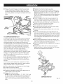
This tool has many features for making its use more pleasant and enjoyable. Safety, performance, and dependability
have been given top priority in the design of this product making it easy to maintain and operate.
_IL WARNING:Readand
understand
all instruc-
tions. Failure to follow all instructions listed below,
may result in electric shock, fire and/or serious
personal injury.
READ ALL iNSTRUCTIONS
[] KNOW YOUR POWER TOOL. Read the operator's
manual carefully. Learn the applications and limitations
as well as the specific potential hazards related to this
tool.
[] GUARD AGAINST ELECTRICAL SHOCK BY PREVENTING BODY CONTACT WITH GROUNDED
SURFACES. For example: pipes, radiators, ranges,
refrigerator enclosures.
[] SECURE WORK. Use clamps or a vise to hold work
when practical, it is safer than using your hand and
frees both hands to operate the tool.
[] DO NOT OVERREACH.
ance at all times.
[] MAINTAIN TOOLS WITH CARE. Keep tools sharp and
clean for better and safer performance. Follow instructions for lubricating and changing accessories.
[] DISCONNECT TOOLS. When not in use, before servicing, or when changing attachments, blades, bits,
cutters, etc., all tools should be disconnected from
power source.
[] AVOID ACCIDENTAL
KEYS AND WRENCHES.
[] USE RECOMMENDED
pieces of wood on the tool while it is in operation.
[] CHECK DAMAGED PARTS. Before further use of
the tool, a guard or other part that is damaged should
be carefully checked to determine that it will operate
properly and perform its intended function. Check for
alignment of moving parts, binding of moving parts,
breakage of parts, mounting and any other conditions
that may affect its operation. A guard or other part that
is damaged must be properly repaired or replaced by
an authorized service center to avoid risk of personal
injury.
Do not use power tools in damp or wet locations or
expose to rain. Keep the work area well lit.
[] KEEP CHILDREN AND VISITORS AWAY. All visitors
should wear safety glasses and be kept a safe distance from work area. Do not let visitors contact tool or
extension cord while operating.
[] USE THE RIGHT DIRECTION OF FEED. Feed work
[] DON'T FORCE THE TOOL. It will do the job better and
safer at the feed rate for which it was designed.
[] USE THE RIGHT TOOL. Do not force the tool or attachment to do a job for which it was not designed.
[] USE THE PROPER EXTENSION CORD. Make sure
your extension cord is in good condition. Use only a
cord heavy enough to carry the current your product
will draw. An undersized cord will cause a drop in line
voltage resulting in loss of power and overheating. A
wire gauge size (A.W.G.) of at least 14 is recommended
for an extension cord 25 feet or less in length. If in
doubt, use the next heavier gauge. The smaller the
gauge number, the heavier the cord.
[] DRESS PROPERLY. Do not wear loose clothing, neckties, or jewelry that can get caught and draw you into
moving parts. Rubber gloves and nonskid footwear
are recommended when working outdoors. Also wear
protective hair covering to contain long hair.
[] ALWAYS WEAR SAFETY GLASSES WITH SIDE
SHIELDS. Everyday eyeglasses have only impactresistant lenses, they are NOT safety glasses.
Consult the
[] NEVER STAND ON TOOL. Serious injury could occur
if the tool is tipped.
[] DO NOT USE IN DANGEROUS ENVIRONMENTS.
[] MAKE WORKSHOP CHILDPROOF with padlocks,
master switches, or by removing starter keys.
ACCESSORIES.
operator's manual for recommended accessories. The
use of improper accessories may result in injury.
Form habit of checking to see that keys and adjusting
wrenches are removed from tool before turning it on.
[] KEEP WORK AREA CLEAN. Cluttered areas and
benches invite accidents. DO NOT leave tools or
STARTING. Be sure switch is off
when plugging in any tool.
[] KEEP GUARDS IN PLACE and in good working order.
[] REMOVE ADJUSTING
Keep proper footing and bal-
into a blade, cutter, or sanding spindle against the
direction or rotation of the blade, cutter, or sanding
spindle only.
[] NEVER LEAVE TOOL RUNNING UNATTENDED.
TURN THE POWER OFF. Don't leave tool until it
comes to a complete stop.
[] PROTECT YOUR LUNGS. Wear a face or dust mask if
the cutting operation is dusty.
[] PROTECT YOUR HEARING. Wear hearing protection
during extended periods of operation.
[] DO NOT ABUSE CORD. Never carry tool by the cord
or yank it to disconnect from receptacle. Keep cord
from heat, oil, and sharp edges.
[] USE OUTDOOR
EXTENSION CORDS. When tool is
used outdoors, use only extension cords with approved ground connection that are intended for use
outdoors and so marked.
[]
KEEP BLADES CLEAN, SHARP, AND WITH SUFFICIENT SET. Sharp blades minimize stalling and
kickback.
[] BLADE COASTS AFTER BEING TURNED OFF.
[]
NEVER USE IN AN EXPLOSIVE ATMOSPHERE.
mal sparking of the motor could ignite fumes.
Nor-
[]
INSPECT TOOL CORDS PERIODICALLY. If damaged,
have repaired by a qualified service technician at an
authorized service facility. The conductor with insulation having an outer surface that is green with or without yellow stripes is the equipment-grounding
conductor. If repair or replacement of the electric cord or plug
is necessary, do not connect the equipment-grounding
conductor to a live terminal. Repair or replace a damaged or worn cord immediately. Stay constantly aware
of cord location and keep it well away from the rotating
blade.
[] DO NOT USE TOOL IF SWITCH DOES NOT TURN IT
ON AND OFF. Have defective switches replaced by an
authorized service center.
[] USE ONLY CORRECT BLADES. Do not use blades
with incorrect size holes. Never use blade washers or
blade bolts that are defective or incorrect. The maximum blade capacity of the saw is 10 in.
[] BEFORE MAKING A CUT, BE SURE ALL ADJUST=
MENTS ARE SECURE.
[] BE SURE BLADE PATH iS FREE OF NAILS. Inspect
for and remove all nails from lumber before cutting.
[] NEVER TOUCH BLADE or other moving parts during
use.
[]
INSPECT EXTENSION CORDS PERIODICALLY and
replace if damaged.
[]
POLARIZED PLUGS. To reduce the risk of electric
shock, this tool has a polarized plug (one blade is
wider than the other). This plug will fit in a polarized
outlet only one way. If the plug does not fit fully in the
outlet, reverse the plug. If it still does not fit, contact a
qualified electrician to install the proper outlet. Do not
change the plug in any way.
[]
KEEP TOOL DRY, CLEAN, AND FREE FROM OIL
AND GREASE. Always use a clean cloth when cleaning. Never use brake fluids, gasoline, petroleum-based
products, or any solvents to clean tool.
[] STAY ALERT AND EXERCISE CONTROL. Watch
what you are doing and use common sense. Do not
operate tool when you are tired. Do not rush.
[] FIRMLY CLAMP OR BOLT the tool to a workbench
table at approximately hip height.
[] NEVER START
COMPONENT
WORKPIECE.
[] DO NOT OPERATE
INFLUENCE
[] ALWAYS SUPPORT LONG WORKPIECES while cutting to minimize risk of blade pinching and kickback.
Saw may slip, walk, or slide while cutting long or heavy
boards.
[] ALWAYS USE A CLAMP to secure the workpiece
when possible.
[] BE SURE THE BLADE CLEARS THE WORKPIECE.
Never start the saw with the blade touching the
workpiece. Allow motor to come up to full speed before starting cut.
[] MAKE SURE THE MITER TABLE AND SAW ARM
BEVEL FUNCTION} ARE LOCKED iN POSiTiON
BEFORE OPERATING YOUR SAW. Lock the miter table
A TOOL WHILE
OF DRUGS,
UNDER
ALCOHOL,
THE
OR ANY
MEDiCATiON.
[] WHEN SERVICING use only identical replacement
parts. Use of any other parts may create a hazard or
cause product damage.
[] USE ONLY RECOMMENDED
ACCESSORIES listed
in this manual or addendums. Use of accessories
that are not listed may cause the risk of personal
injury. Instructions for safe use of accessories are
included with the accessory.
[] DOUBLE CHECK ALL SETUPS. Make sure blade is
tight and not making contact with saw or workpiece
before connecting to power supply.
or
[] KEEP HANDS AWAY FROM CUTTING AREA. Do not
reach underneath work or in blade cutting path with your
hands and fingers for any reason. Always turn the power off.
A TOOL WHEN ANY ROTATING
iS iN CONTACT
WiTH
THE
[]
by securely tightening the miter lock lever. Lock the saw
arm (bevel function) by securely tightening the bevel
lock lever.
USE THIS SAW TO CUT WOOD, WOOD PRODUCTS,
AND SOME PLASTICS ONLY. DO NOT CUT METALS,
CERAMICS OR MASONRY PRODUCTS.
[] BEFORE MOVING THE SAW, unplug the saw then
lock the miter, bevel, slide, and power head positions.
[] NEVER USE A LENGTH STOP ON THE FREE SCRAP
END OF A CLAMPED WORKPIECE. NEVER hold
onto or bind the free scrap end of the workpiece in any
operation. If a work clamp and length stop are used
together, they must both be installed on the same side
of the saw table to prevent the saw from catching the
loose end and kicking up.
[] NEVER cut more than one piece at a time. DO NOT
STACK more than one workpiece on the saw table at a
time.
[] NEVERPERFORM
[] ALWAYS STAY ALERT! Do not allow familiarity (gained
from frequent use of your saw) to cause a careless
mistake. ALWAYS REMEMBER that a careless fraction
of a second is sufficient to inflict severe injury.
[] NEVER hand hold a workpiece that is too small to be
clamped. Keep hands clear of the cutting area.
[] MAKE SURE WORK AREA HAS AMPLE LIGHTING
to see the work and that no obstructions will interfere
with safe operation BEFORE performing any work using your saw.
ANY OPERATION FREEHAND.
Always place the workpiece to be cut on the miter
table and position it firmly against the fence as a backstop. Always use the fence.
[] NEVER reach behind, under, or within three inches
of the blade and its cutting path with your hands and
fingers for any reason.
[] NEVER reach to pick up a workpiece, a piece of scrap,
or anything else that is in or near the cutting path of the
blade.
[] AVOID AWKWARD OPERATIONS AND HAND POSITIONS where a sudden sup could cause your hand
to move into the blade. ALWAYS make sure you have
good balance. NEVER operate the miter saw on the
floor or in a crouched position.
[] ALWAYS TURN OFF THE SAW before disconnecting
it to avoid accidental starting when reconnecting to
power supply. NEVER leave the saw unattended while
connected to a power source.
[] THIS TOOL has the following markings:
a)
b)
c)
d)
e)
f)
[] NEVER stand or have any part of your body in line with
the path of the saw blade.
[] ALWAYS release the power switch and allow the
saw blade to stop rotating before raising it out of the
workpiece.
g)
h)
i)
Wear eye protection.
Keep hands out of path of saw blade
Do not operate saw without guards in place.
Do not perform any operation freehand.
Never reach around saw blade.
Turn off tool and wait for saw blade to stop before
moving workpiece or changing settings.
Disconnect power (or unplug tool as applicable)
before changing blade or servicing.
No load speed.
Blade direction of rotation arrow.
[] DO NOT TURN THE MOTOR SWITCH ON AND OFF
RAPIDLY. This could cause the saw blade to loosen
and could create a hazard. Should this ever occur,
stand clear and allow the saw blade to come to a complete stop. Disconnect the saw from the power supply
and securely retighten the blade bolt.
[] ALWAYS MAKE SURE THE SAW BLADE HAS
CLEARANCE OF ALL OBSTRUCTIONS BEFORE
TURNING THE SAW ON.
[] IF ANY PART OF THIS MITER SAW IS MISSING or
should break, bend, or fail in any way, or should any
electrical component fail to perform properly, shut off
the power switch, remove the miter saw plug from the
power source and have damaged, missing, or failed
parts replaced before resuming operation.
[] ALWAYS carry the tool only by the carrying handles.
[] IF THE POWER SUPPLY CORD IS DAMAGED, it
must be replaced only by the manufacturer or by an
authorized service center to avoid risk.
[] MAKE SLIDING CUTS by pulling the saw forward, then
pushing the saw blade down atthe front of the workpiece
then sliding it back toward the rear of the saw. DO NOT
pull the saw toward you while making a cut.
[] AVOID direct eye exposure when using the laser guide.
[] THIS SAW CAN TIP OVER if the saw head is released
suddenly and the saw is not secured to a work surface.
ALWAYS secure this saw to a stable work surface
before any use to avoid serious personal injury.
[] SAVE THESE INSTRUCTIONS.
Refer to them fre-
quently and use to instruct other users. If you loan
someone this tool, loan them these instructions also.
_
WARNING:
Some dust created by power sanding, sawing, grinding, drilling, and other construction
contains chemicals known to cause cancer, birth defects or other reproductive
chemicals are:
•
activities
harm. Some examples of these
lead from lead-based paints,
crystalline silica from bricks and cement and other masonry products, and
arsenic and chromium from chemically-treated
lumber.
Your risk from these exposures varies, depending on how often you do this type of work. To reduce your exposure
to these chemicals: work in a well ventilated area, and work with approved safety equipment, such as those dust
masks that are specially designed to filter out microscopic particles.
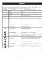
Someof the followingsymbolsmaybe usedon this tool. Pleasestudythem andlearntheir meaning.Proper
interpretation
ofthesesymbolswill allowyouto operatethetoolbetterandsafer.
SYMBOL
NAME
DESIGNATION/EXPLANATION
V
Volts
Voltage
A
Am pe res
Current
Hz
Hertz
Frequency (cycles per second)
W
Watt
Power
Minutes
Time
Alternating Current
Type of current
Direct Current
Type or a characteristic
no
No Load Speed
Rotational speed, at no load
[]
Class II Construction
Double-insulated
.../min
Per Minute
Revolutions, strokes, surface speed, orbits etc., per minute
@
Wet Conditions Alert
Do not expose to rain or use in damp locations.
Read The Operator's Manual
To reduce the risk of injury, user must read and understand
operator's manual before using this product.
Eye Protection
Always wear safety goggles or safety glasses with side shields and,
as necessary, a full face shield when operating this product.
Safety Alert
Precautions that involve your safety.
No Hands Symbol
Failure to keep your hands away from the blade will result in
serious personal injury.
Hot Surface
To reduce the risk of injury or damage, avoid contact with any
hot surface.
min
O
@
®
of current
construction
Thefollowingsignalwordsandmeanings
areintendedto explainthelevelsof riskassociated
withthisproduct.
SYMBOL
,_
SIGNAL
MEANING
DANGER:
Indicates an imminently hazardous situation, which, if not avoided, will
result in death or serious injury.
WARNING:
Indicates a potentially hazardous situation, which, if not avoided, could
result in death or serious injury.
CAUTION:
Indicates a potentially hazardous situation, which, if not avoided, may
result in minor or moderate injury.
CAUTION:
(Without Safety Alert Symbol) Indicates a situation that may result in
property damage.
SERVICE
_
Servicing requires extreme care and knowledge and
should be performed only by a qualified service technician. For service we suggest you return the product to
your nearest SEARS PARTS AND REPAIR SERVICE
CENTER for repair. When servicing, use only identical
replacement parts.
WARNING:
To avoid serious personal injury, do
not attempt to use this product until you read thoroughly and understand completely the operator's
manual. If you do not understand the warnings and
instructions in the operator's manual, do not use this
product. Call the Craftsman Consumer Helpline at
1-800-932-3188 for assistance.
411_ILWARNING:
The operation of any power tool can result in foreign objects being thrown into your eyes, which can
result in severe eye damage. Before beginning power tool operation, always wear safety goggles or
safety glasses with side shields and, when needed, a full face shield. We recommend Wide Vision
Safety Mask for use over eyeglasses or standard safety glasses with side shields. Always use eye
protection which is marked to comply with ANSI Z87.1.
SAVE THESE INSTRUCTIONS
DOUBLE
INSULATION
Double insulation is a concept in safety in electric power
tools, which eliminates the need for the usual three-wire
grounded power cord. All exposed metal parts are
isolated from the internal metal motor components with
protecting insulation. Double insulated tools do not need
to be grounded.
A
WARNING: The double insulated system is
intended to protect the user from shock resulting
from a break in the tool's internal insulation. Observe
all normal safety precautions to avoid electrical
shock.
NOTE: Servicing of a product with double insulation
requires extreme care and knowledge of the system and
should be performed only by a qualified service technician. For service, we suggest you return the product to
your nearest Sears or other qualified service center for
repair. Always use original factory replacement parts when
servicing.
ELECTRICAL
EXTENSION
CORDS
When using a power tool at a considerable distance from
a power source, be sure to use an extension cord that has
the capacity to handle the current the product will draw.
An undersized cord will cause a drop in line voltage, resulting in overheating and loss of power. Use the chart to
determine the minimum wire size required in an extension
cord. Only round jacketed cords listed by Underwriter's
Laboratories (UL) should be used.
When working outdoors with a product, use an extension
cord that is designed for outside use. This type of cord is
designated with "WA" on the cord's jacket.
Before using any extension cord, inspect it for loose or
exposed wires and cut or worn insulation.
**Ampere rating (on product faceplate)
0-2.0
2.1-3.4 3.5-5.0 5.1-7.0 7.1-12.0 12.1-16.0
Cord Length
Wire Size (A.W.G.)
25'
16
16
16
16
14
14
50'
16
16
16
14
14
12
100'
16
16
14
12
10
--
CONNECTION
This product has a precision-built electric motor. It should
be connected to a power supply that is 120 volts, 60 Hz,
AC only (normal household current). Do not operate this
product on direct current (DC). A substantial voltage drop
will cause a loss of power and the motor will overheat. If
the product does not operate when plugged into an outlet,
double-check the power supply.
**Used on 12 gauge - 20 amp circuit
NOTE: AWG = American Wire Gauge
A
A
WARNING:
Keep the extension cord clear of the
working area. Position the cord so that it will not get
caught on lumber, tools or other obstructions while
you are working with a power tool. Failure to do so
can result in serious personal injury.
WARNING:
Check extension cords before each
use. If damaged replace immediately. Never use
product with a damaged cord since touching the
damaged area could cause electrical shock resulting
in serious injury.
Anti-KickbackPawls
(radial arm and table saws)
A device which, when properly installed and maintained,
is designed to stop the workpiece from being kicked back
toward the front of the saw during a ripping operation.
Arbor
The shaft on which a blade or cutting tool is mounted.
Bevel Cut
A cutting operation made with the blade at any angle
other than 90 ° to the table surface.
Chamfer
A cut removing a wedge from a block so the end (or part
of the end) is angled rather than at 90 ° .
Compound Cut
A cross cut made with both a miter and a bevel angle.
Cross Cut
A cutting or shaping operation made across the grain or
the width of the workpiece.
Cutter Head (planers and jointer planers)
A rotating cutterhead with adjustable blades or knives.
The blades or knives remove material from the workpiece.
Dado Cut
Non-Through Cuts
Any cutting operation where the blade does not extend
completely through the thickness of the workpiece.
Push Blocks (for jointer planers)
Device used to feed the workpiece over the jointer planer
cutterhead during any operation. This aid helps keep the
operator's hands well away from the cutterhead.
Push Blocks and Push Sticks (for table saws)
Devices used to feed the workpiece through the saw
blade during cutting operations. A push stick (not a push
block) should be used for narrow ripping operations.
These aids help keep the operator's hands well away from
the blade.
Pilot Hole (drill presses)
A small hole drilled in a workpiece that serves as a guide
for drilling large holes accurately.
Resaw
A cutting operation to reduce the thickness of the
workpiece to make thinner pieces.
Resin
A sticky, sap-based substance that has hardened.
A non-through cut which produces a square-sided notch
or trough in the workpiece (requires a special blade).
Featherboard
Revolutions Per Minute (RPM)
The number of turns completed by a spinning object in
one minute.
A device used to help control the workpiece by guiding it
securely against the table or fence during any ripping
operation.
FPM or SPM
Feet per minute (or strokes per minute), used in reference
to blade movement.
Ripping or Rip Cut
A cutting operation along the length of the workpiece.
Freehand
Performing a cut without the workpiece
fence, miter gauge, or other aids.
being guided by a
Gum
A sticky, sap-based residue from wood products.
Heel
Alignment of the blade to the fence.
Kerr
The material removed by the blade in a through cut or the
slot produced by the blade in a non-through or partial cut.
Kickback
A hazard that can occur when the blade binds or stalls,
throwing the workpiece back toward operator.
Leading End
The end of the workpiece
Miter Cut
pushed into the tool first.
A cutting operation made with the workpiece at any angle
to the blade other than 90 °.
Riving Knife/Spreader/Splitter
(table saws)
A metal piece, slightly thinner than the blade, which helps
keep the kerf open and also helps to prevent kickback.
Saw Blade Path
The area over, under, behind, or in front of the blade. As
it applies to the workpiece, that area which will be or has
been cut by the blade.
Set
The distance that the tip of the saw blade tooth is bent (or
set) outward from the face of the blade.
Snipe (planers)
Depression made at either end of a workpiece by cutter
blades when the workpiece is not properly supported.
Through Sawing
Any cutting operation where the blade extends completely
through the thickness of the workpiece.
Throw-Back
The throwing back of a workpiece usually caused by the
workpiece being dropped into the blade or being 9laced
inadvertently in contact with the blade.
Workpiece or Material
The item on which the operation is being done.
Worktable
Surface where the workpiece rests while performing a
cutting, drilling, planing, or sanding operation.
PRODUCT
SPECiFICATiONS
Blade Diameter .............................
Arbor .....................................
10 in.
5/8 in.
No Load Speed ..................
Input ................
Cutting Capacity with Miter at 0°/Bevel 0°:
Maximum nominal lumber sizes ................... 2 x 12, 4 x 4
5,000 r/rain. (RPM)
Cutting Capacity with Miter at 45°/Bevel 0°:
120 V, 60 Hz, AC Only, 15 Amps.
,_
,_/_
,,,,L
DEPTHCONTROL
,
r-_
/f__
Maximum nominal lumber sizes ............................ 2 x 10
Cutting Capacity with Miter at 0°/Bevel 45°:
) /
Maximum nominal lumber sizeS.o
............... '_........... 2 x 12
Cutting Capacity with Miter at 45/Bevel 45 :
KNOB
/ /
Maximum nominal lumber sizes ............................ 2 x 10
\
[
LOCKKNOB
SWITCH
"D" HANDLE{
SCALE
GUARD
DUST
GUIDE
LOWERBLADE
GUARD
DUST
BAG
"NO HANDS"
LABEL
CROWN
MOLDING
STOP
BEVEL
STOPPiN
"NO HANDS"
BOUNDARYLINE
SLIDINGMITER
FENCE
THROAT
PLATE
FENCE RELEASE
LEVER
CONTROLARM
MICROADJUST
KNOB
BLADEWRENCH
STORAGE
MITER
SCALE
BASE
STOP
BLOCK
TABLE
ROLLER
SUPPORT
MITER
TABLE
EXTENSION
POSITIVE
STOP(S)
MITERLOCK
HANDLE
RELEASE
KNOB
WORK
CLAMP
MITERLOCK
PLATE
Fig. 1
10
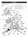
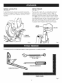
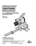
KNOW YOUR
COMPOUND
MITER
SAW
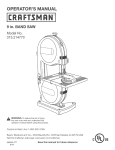
See Figure 1.
CARRYING
HANDLE_
LOCK
The safe use of this product requires an understanding of
the information on the tool and in this operator's manual
as well as a knowledge of the project you are attempting.
Before use of this product, familiarize yourself with all
operating features and safety rules.
RELEASE_J_
10 in. BLADE
A 10 in. blade is included with your compound miter saw.
It will cut materials up to11-1/2 in. wide, depending upon
the angle at which the cut is being made.
15 AMP
( /
., LOCK
MOTOR
Your saw has a powerful 15 amp belt-driven motor with
sufficient power to handle tough cutting jobs. It is made with
all ball bearings, and has externally accessible brushes for
ease of servicing.
Nj MICR0"
\
BEVEL LOCK KNOB
The bevel lock knob securely locks your compound miter
saw at desired bevel angles. A positive stop adjustment
screw has been provided on each side of the saw arm.
These adjustment screws are for making fine adjustments
at 0 ° and 45 °.
BEVEL STOP
Fig. 2
MICRO-ADJUST
PIN
KNOB
The micro-adjust feature allows rotation of the miter table
in small increments for the most accurate cuts. With the
miter lock handle unlocked, lift and hold the miter lock
plate then push the micro-adjust knob in while giving the
knob a slight turn. Once set to the desired position,
retighten the miter lock handle then cancel the microadjust feature by pulling out the side release knob.
HANDLE
See Figure 2.
For convenience when carrying or transporting the miter
saw, a carrying handle has been provided on top of the
saw arm. To transport, turn off and unplug the saw, then
lower the saw arm and lock it in the down position. Lock
saw arm by pushing the lock pin to the left. Lock bevel
and miter lock levers; lock slide lock knob.
MITER LOCK
See Figure 2.
HANDLE
The miter lock handle securely locks your saw at desired
miter angles.
POSITIVE STOPS ON MITER TABLE
Positive stops have been provided at 0 °, 15 °, 22.5 °, 31.6 °,
and 45 ° on both the left and right side of the miter table.
NOTE: DO NOT perform any cutting operation with the
saw in the locked position.
MOLDING
BEVEL
STOPPiN
SAWARM LOCKEDIN DOWN POSiTiON
1. Override (pin pulled completely out)
2. The 0 ° - 48 ° position for crown molding (pin pushed in)
3. Stops at 33.9 ° and 45 °
CARRYING
°
MITERLOCK
PLATE
MITER LOCK
HANDLE
The bevel stop pin has several positions:
CROWN
_
ROLLER
STOP
SUPPORT
With the roller support installed, the workpiece will glide
smoothly over the table extensions.
The crown molding stop makes positioning crown molding
vertically against the fence easier.
SLIDE BAR
ELECTRIC BRAKE
An electric brake has been provided to quickly stop blade
rotation after the switch is released.
When unlocked, the saw arm will glide forward and
backward the length of the slide bar for cutting various
workpiece widths.
LASER GUIDE
For more accurate cuts, a laser guide is included with your
miter saw. When used properly, the laser guide makes
accurate, precision cutting simple and easy.
LOWER BLADE GUARD
SLIDING
MITER
FENCE
Hold the workpiece securely against the miter fence when
making all cuts. The sliding feature allows both fences (left
and right) to be moved when making bevel or compound
CutS.
The lower blade guard is made of shock-resistant, seethrough plastic that provides protection from each side
of the blade. It retracts over the upper blade guard as the
saw is lowered into the workpiece.
Slide the miter fences by pushing and holding the fence
release levers. Once the desired position of the fence is
determined, release the lever to secure the fence.
11
SPINDLELOCK
SWITCH
BUTTON
TRIGGER
See Figure 3.
See Figure 4.
A spindle lock button has been provided for locking the
spindle which keeps the blade from rotating. Depress and
hold the lock button while installing, changing, or removing blade.
The saw will not start until you depress the switch lock
with your thumb then squeeze the switch trigger. To
prevent unauthorized use of the compound miter saw,
disconnect it from the power supply and lock the switch
in the OFF position. To lock the switch, install a padlock
(not included) through the hole in the switch trigger. A lock
with a long shackle up to 9/32 in. diameter may be used.
When the lock is installed and locked, the switch is
inoperable. Store the padlock key in another location.
SWITCH
TRIGGER
ItlPADLOCK
SPINDLE
LOCKBUTTON
Fig. 4
Fig. 3
The following tools (not included) are needed for making adjustments
or installing the blade:
PHiLLiPSSCREWDRIVER
FRAMINGSQUARE
Fig. 5
12
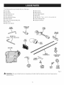
Thefollowingitemsareincludedwithyourmitersaw:
[] DustBag
[] DustGuide
[] TableExtension(2)
[] ClampBracket
[] ClampBracketScrew
[] RollerSupport
[] LevelerwithattachedWingNut
[] StopBlock
[] MiterLockHandle
BLADE
WRENCH
[]
[]
[]
[]
[]
[]
[]
MITER LOCK
HANDLE
WorkClamp
BladeWrench
OuterBladeWasher
BladeBolt
HexKey(4),1/16in.,4 mm,5 mm,and8 mm
CrownMoldingStop
Operator'sManual
WORK
CLAMP
ROLLER
SUPPORT
HEXKEY (4),
1/16 in., 4 ram, 6 ram, 8 mm
STOP
BLOCK
DUSTBAG
TABLE
EXTENSION (2)
CROWN
MOLDING
STOP
\
CLAMP
BRACKET
SCREW
LEVELERWiTH
WING NUT
F
BLADE
BOLT
OUTER
BLADE
WASHER
Fig. 6
,_
WARNING:
The use of attachments
or accessories not listed might be hazardous and could cause serious
personal injury.
13
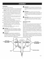
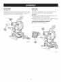
UNPACKING
Thisproductrequiresassembly.
[] Carefullyliftsawfromthe cartonbythecarryinghandle
andthesawbase,andplaceit ona levelworksurface.
NOTE:Thissawis heavy.Toavoidbackinjury,liftwith
yourlegs,notyourback,andgethelpwhenneeded.
[] Thissawhasbeenshippedwiththesawarmsecured
inthedownposition.Toreleasethesawarm,push
downonthetop ofthesawarm,cutthetie-wrap,and
pulloutonthe lockpin.
[] Liftthesawarmbythe handle.Handpressureshould
remainonthesawarmto preventsuddenriseupon
releaseofthetie wrap.
[] Inspectthetoolcarefullyto makesurenobreakage
or
damageoccurredduringshipping.
[] Donotdiscardthepackingmaterialuntilyouhave
carefullyinspectedandsatisfactorily
operatedthetool.
[] Thesawis factorysetforaccuratecutting.After
assembling
it, checkforaccuracy.
If shippinghas
influenced
thesettings,referto specificprocedures
explainedinthismanual.
[] If anypartsaredamaged
or missing,pleasecall
1-800-932-3188
forassistance.
WARNING:
If any parts are damaged or missing
do not operate this tool until the parts are replaced.
Failure to heed this warning could result in serious
personal injury.
A
WARNING:
Do not connect to power supply until
assembly is complete. Failure to comply could result
in accidental starting and possible serious personal
injury.
A
A
WARNING:
Do not start the miter saw without
checking for interference between the saw blade and
the sliding miter fences. Damage could result to the
blade if it strikes the miter fence during operation of
the saw.
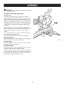
WARNING:
Always make sure the compound miter
saw is securely mounted to a workbench. Failure
to heed this warning can result in serious personal
injury.
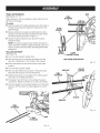
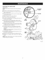
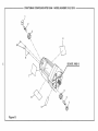
MOUNTING
HOLES
See Figure 7.
The compound miter saw should be permanently mounted to a firm supporting surface such as a workbench.
Four bolt holes have been provided in the saw base for
this purpose. Each of the four mounting holes should be
bolted securely using 3/8 in. machine bolts, lock washers,
and hex nuts (not included). Bolts should be of sufficient
length to accommodate the saw base, lock washers, hex
nuts, and the thickness of the workbench. Tighten all four
bolts or screws securely. Do not use screws if mounting to
a leg stand.
The hole pattern for mounting to a workbench is shown in
figure 7. Carefully check the workbench after mounting to
make sure that no movement can occur during use. If any
tipping, sliding, or walking is noted, secure the workbench
to the floor before operating.
WARNING:
Do not attempt to modify this tool
or create accessories not recommended for use
with this tool. Any such alteration or modification is
misuse and could result in a hazardous condition
leading to possible serious personal injury.
TRACEHOLES
ATTHESELOCATIONSFOR
HOLEPATTERN
TRACEHOLES
AT THESELOCATIONSFOR
HOLEPATTERN
MOUNTINGSURFACE
BASE
Fig. 7
14
NOTE:Manyoftheillustrations
inthismanualshowonly
portionsofthe compoundmitersaw.Thisis intentional
so
thatwecanclearlyshowpointsbeingmadeinthe
illustrations.
Neveroperatethe sawwithoutall guards
securelyin place and in good operating condition.
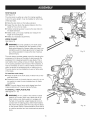
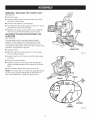
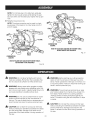
LOCKING
/ UNLOCKING
"D" HANDLE
LOCK
PiN
THE SAW ARM
See Figure 8.
When locking and unlocking the saw arm, it is not
necessary to loosen the depth control knob.
To unlock and raise the saw arm:
[] Firmly grasp the "D" handle and apply downward pressure while at the same time pulling the lock pin out and
away from the saw housing.
[] Release the lock pin and slowly raise the saw arm.
To relock the saw arm:
[] Firmly grasp the "D" handle and apply downward pressure while at the same time pulling the lock pin out and
away from the saw housing.
[] Release the lock pin allowing it to lock the saw into
place.
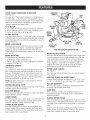
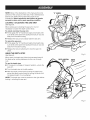
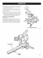
USING
THE DEPTH
STOP
Fig. 8
See Figure 9.
When used, the depth stop limits the downward travel of
the blade when cutting dadoes and other non-through
DEPTHCONTROL
KNOB
CutS.
DEPTH
STOP
To use the depth stop:
[] If the saw is in storage or transport position, unlock the
saw arm.
[] Turn the depth stop to the left position.
[] With the depth control knob touching the depth stop,
adjust the depth control knob by turning the knob until
the desired depth of cut is attained.
NOTE: The depth stop must be pushed to the right before
locking / unlocking the saw arm.
Fig. 9
15
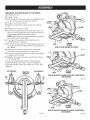
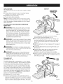
DUST GUIDE
DUST BAG
See Figure 10.
See Figure 11.
Slide the end of the dust guide into the exhaust port in the
upper blade guard. Turn the guide so that the open end is
facing down or toward the rear of the saw.
A dust bag is provided for use on this miter saw. It fits
over the dust guide on the upper blade guard.
To install:
[] Squeeze the two metal clips to open the mouth of the
bag and slide it on to the dust guide.
[] Release the clips. The metal ring in the bag should lock
in between the grooves on the dust guide.
EXHAUST
PORT
To remove the dust bag for emptying:
[] Reverse the above procedure.
DUST
GUIDE
DUST
GUIDE
©
DUST
BAG
Fig. 10
Fig. 11
16
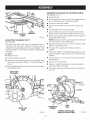
TABLEEXTENS(ONS
BASE
See Figures 12- 13.
Table extensions can be installed on either the left or the
TABLE
EXTENSION
right side of the base.
To instal(:
[] Insert the ends of the table extensions into the holes in
the side of the base and adjust the extensions to the
desired length.
CLAMP
BRACKET
[] Secure extensions in place by positioning the clamp
bracket under the extension beneath the base. Orient
the clamp bracket as shown in figure 13.
[] Using the clamp bracket screw, secure the clamp
bracket in place.
NOTE: The clamp bracket screw threads through the
clamp bracket and tightens against bracket support on
bottom of base, securing clamp bracket against table
extensions.
ROLLER
SUPPORT
CLAMP
BRACKETSCREW
See Figure 14,
[] Turn the roller support upside down.
SAWVIEWEDFROMBOTTOM
[] Spin the wing nut on the leveler clockwise until the
wing nut is positioned in the middle of the threads.
[] Screw the leveler into the center brace of the roller
Fig. 13
support.
[] Turn the roller support upright.
WING NUT
[] With the table extensions secured in the saw's base,
slide the roller support onto the extensions.
ROLLER
SUPPORT
TABLE
EXTENSION
[] Tighten the wing nut on the back of the roller support
securing it to the table extensions.
[] The leveler must sit firmly on the surface the saw is
mounted to. Adjust the leveler up or down as needed.
[] Once the leveler is in the proper position, turn the lever
wing nut until the wing nut is tight against the center
brace.
LEVELER
WING NUT
TABLE
EXTENSION
Fig. 14
BASE
Fig. 12
17
STOPBLOCK
See Figure 15,
The stop block is useful as a stop for making repetitive
cuts to the same length. It can be installed on either side
of the saw base.
[] Slide the stop block on the table extension.
[] Adjust the stop block the desired distance from the
blade for the cut to be made.
STOP
BLOCK
[] Tighten small wing screw to secure the stop block to
the table extension.
[] Make a test cut in scrap material and measure the
length of the workpiece.
TABLE
EXTENSION
[] Make any necessary adjustments.
WORK
CLAMP
See Figure 16.
_11_ WARNING:
In some operations, the work clamp
BASE
assembly may interfere with the operation of the
blade guard assembly. Always make sure there is no
interference with the blade guard prior to beginning
any cutting operation to reduce the risk of serious
personal injury.
Fig. 15
The work clamp provides greater control by clamping the
workpiece to the fence or the table. It also prevents the
workpiece from creeping toward the saw blade. This is
very helpful when cutting compound miters. Depending
on the cutting operation and the size of the workpiece, it
may be necessary to use a C-clamp instead of the work
clamp to secure the workpiece prior to making the cut.
The work clamp can be installed and used on either side
of the blade.
To instal( the work clamp:
[] Place the shaft of the work clamp in either hole on the
saw table base.
[] Rotate the knob on the work clamp to move it in or out
as needed or press the quick release lever for faster
positioning.
NOTE: The work clamp has a quick release lever that
makes positioning of the work clamp effortless.
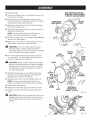
TO INSTALL
/ REPLACE
BLADE
See Figures 17- 19.
A
WARNING:
A 1 0 in. blade is the maximum blade
capacity of the saw. Never use a blade that is too
thick to allow outer blade washer to engage with
the flats on the spindle. Larger blades will come in
contact with the blade guards, while thicker blades
will prevent the blade screw from securing the blade
on the spindle. Either of these situations could result
in a serious accident and can cause serious personal
injury.
QUICK
RELEASE
LEVER
BASE
WORK
CLAMP
Fig. 16
18
[] Unplugthe saw.
[] Loosenthe phillipsscrewonthebladeboltcoveruntil
thecovercanberaised.
[] Gentlyraisethe lowerbladeguardbracketsothat
lowerbladeguardandbladeboltcovercanberotated
upandbackto exposethe bladebolt.
[] Depressthespindlelockbuttonandrotatetheblade
boltuntilthespindlelocks.
[] Usingthe bladewrenchprovided,loosenandremove
laserscrewor bladebolt.
NOTE:Thelaserscrew(bladebolt)haslefthand
threads.Turnbladeboltclockwiseto loosen.
[] Removethe laserguideor outerbladewasher.Donot
removeinnerbladewasher.
[] Wipea dropof oilontoinnerbladewasherandouter
bladewasherwheretheycontactthe blade.
,_
WARN(NG:
NOTE:BEFOREUSE, REPLACE
SCREWANDTIGHTENSECURELY
TO PREVENTGUARDMOVElVlENT
\
PHiLLiPS
SCREW
If the inner blade washer has been
Fig. 1 7
removed, replace it before placing the blade on
the spindle. Failure to do so could cause an accident
since the blade will not tighten properly.
BLADE
BOLTCOVER
[] Fit the saw blade inside the upper blade guard and
onto the spindle. The blade teeth point downward at
the front of saw as shown in figure 17.
,_
CAUTION:
Always install the blade with the blade
TO
LOOSEN
[] Replace the laser guide or outer blade washer (see
instructions on the following page). The double "D"
flats align with the flats on the spindle.
FLAT(S)
ONSPINDLE
[] Depress spindle lock button and replace blade bolt.
TO
NOTE: The laser screw (blade bolt) has left hand
threads. Turn blade bolt counterclockwise to tighten.
[] Tighten blade bolt securely.
LASER
SCREW
[] Replace the lower blade guard and blade bolt cover.
LASER
[] Retighten the phillips screw securing the blade bolt
cover.
CAUT(ON:
LOWER
BLADE
GUARD
BLADE
teeth and the arrow printed on the side of the blade
pointing down at the front of the saw. The direction
of blade rotation is also stamped with an arrow on
the upper blade guard.
,_
PHILLIPS
SCREW
INNERBLADE
WASHERWiTH
DOUBLE"D" FLATS
Fig. 18
Make sure the spindle lock button is not
engaged before reconnecting saw to power source.
Never engage spindle lock button when blade is
rotating.
SPINDLE
LOCK
BUTTON
Fig. 19
19
_
DANGER:
Laser radiation. Avoid direct eye contact
with light source.
ALIGNING THE LASER GUIDE
See Figure 20.
LINE
The laser guide will generate a laser line on the work
surface when the saw blade is spinning. The laser line will
appear as a broken line on the workpiece when the saw
arm is in the uppermost position and the motor switch is
activated. This broken line will let you see your mark and
your laser guide line at the same time, and will assist you
in lining up your mark for more accurate cutting of the
workpiece.
Align the laser line and your mark with the blade at the
uppermost position. Once both lines are in alignment, do
not move the workpiece until after you have finished
cutting.
As the blade assembly is lowered toward the workpiece,
the broken line will become solid.
Follow the directions below for using the laser guide:
Removing the mark:
Position the laser line on the left edge of your mark on the
work surface in order to remove the mark.
Fig. 20
To cut the mark:
Position the laser line near or over your mark on the work
surface in order to cut the mark.
To leave the mark:
Position the laser line near the right edge of your mark on
the work surface in order to leave the mark.
After you have become familiar with using the laser guide,
you will be able to remove, cut, or leave your mark on the
work surface. Practice will teach you the correct position
for aligning the laser line with your mark.
20
REMOVING/
REPLACING
THE THROAT
PLATE
See Figure 21.
[] Unplug the saw.
[] Using the blade wrench provided, loosen the screws
securing the throat plate.
[] Lift the throat plate from the saw base.
[] To reinstall the throat plate, align the holes in the throat
plate with the holes in the saw base.
[] Retighten the screws, being careful not to overtighten
which can cause the throat plate to bow or bend.
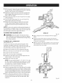
CENTERING
THE SAW BLADE
SLIDE BARS
BETWEEN
BLADE
WRENCH
THE
See Figure 22.
The saw blade should be centered (approximately)
between the two pieces of the throat plate and there
should be no play between the right slide bar and the
pivot assembly. Standing in front of the saw, make a visual
inspection. If adjustment is required:
THROATPLATE
[] Unplug the saw.
[] With the miter at 0° and the bevel at 0°, lock the saw
into the transport position.
Fig. 21
[] Loosen the jam nut on the top and bottom gib screws
as shown.
[] Loosen the top gib screws.
[] Tighten or loosen the lower gib screw as required to
center the blade between the two pieces of the throat
plate.
[] Once centered, tighten the lower two jam nuts.
NOTE: To minimize play in the slide bars, gradually tighten
the two top gib screws while sliding the saw back and
forth over the slide bars. Tighten the top jam nuts.
JAM NUT
GIB
SCREW
(3)
SLIDE BAR
PIVOT
ASSEMBLY
Fig. 22
21
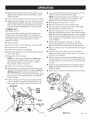
SQUARINGTHE
SAW BLADE
See Figures 23 - 27.
TO THE FENCE
[] Unplug the saw.
[] Pull the saw arm all the way down and engage the lock
pin to hold the saw arm in transport position.
[] Loosen the miter lock handle.
[] Rotate the miter table until the pointer is positioned
at 0°.
[] Retighten the miter lock handle.
[] Lay a framing square flat on the miter table. Place one
leg of the square against the fence. Slide the other leg
of the square against the flat part of blade.
NOTE: Make sure that the square contacts the flat part
of the blade, not the blade teeth.
[] The edge of the square and the blade should be
parallel as shown in figure 24.
FENCE
BASE
FRAMING
SQUARE
ViEW OF BLADESQUAREWiTH FENCE
[] If the front or back edge of the blade angles away from
the square as shown in figures 25 and 26, adjustments
are needed.
Fig. 24
[] Using a 6 mm wrench, loosen the hex screws that
secure the mounting bracket to the miter table.
[] Rotate the mounting bracket left or right until the blade
is parallel with the square.
[] Retighten the screws securely and recheck the bladeTheto-fence
saw hasalignment.
several scale indicators. After squaring
adjustments have been made, it may be necessary to
loosen the indicator screws and reset them to zero. See
Figure 27,
HEXSCREW(S)
MOUNTING
BRACKET
HEXSCREW(S)
BASE
SQUARE
VIEW OF BLADENOTSQUAREWiTH FENCE,ADJUSTMENTS
ARE REQUIRED
Fig. 25
FENCE \ "_,_j_'---__
/
BASE
FRAMING
SQUARE
VIEW OFBLADENOTSQUAREWITH FENCE,ADJUSTMENTS
AREREQUIRED
Fig. 26
Fig. 23
22
SQUARING
THE BLADE
See Figures 29 - 31.
TO THE MITER
TABLE
[] Unplug the saw.
[] Pull the saw arm all the way down and engage the lock
pin to hold the saw arm in transport position.
[] Loosen the miter lock handle.
[] Rotate the miter table until the pointer is positioned
at 0°.
MITER
SCALEiNDiCATOR
[] Securely tighten the miter lock handle.
[] Loosen bevel lock knob and set saw arm at 0° bevel
SCALE
iNDiCATOR
(blade set 90 ° to miter table). Tighten bevel lock knob.
SCREW
[] Place a combination square against the miter table and
the flat part of saw blade.
Fig. 27
ADJUSTING
THE BEVEL PIVOT
NOTE: Make sure that the square contacts the flat part
of the saw blade, not the blade teeth.
See Figure 28.
[] Rotate the blade by hand and check the blade-to-table
alignment at several points.
The saw should freely pivot when the bevel lock knob is
"unlocked"
and the saw is beveled. A "grating" sound
indicates that the bevel needs to be loosened slightly. If the
movement is tight or there is play in the pivot, an adjustment
is required.
[] The edge of the square and the blade should be
parallel.
[] If the top or bottom of the blade angles away from the
square as shown in figures 30 and 31, adjustments are
needed.
To adjust:
[] Unplug the saw.
[] Loosen the jam nut on the top and bottom gib screws.
See Figure 22.
[] Loosen the bevel lock knob.
[] Using the 8 mm hex key provided, turn the socket head
cap screw clockwise to tighten or counterclockwise to
loosen.
[] Once all adjustments
the bevel lock knob.
[] Loosen the top gib screws.
[] Tighten or loosen the lower gib screws as required to
square the blade to the table.
have been made, securely tighten
[] Once blade is square with table, tighten the lower two
jam nuts.
SOCKETHEAD
CAPSCREW
COMBINATION
SQUARE
BEVELLOCK
KNOB
TABLE
CORRECTViEW OF BLADE
SQUAREWiTH MITER TABLE
Fig. 28
23
Fig. 29
NOTE:Tominimizeplayin the slide bars, gradually
tighten the two top gib screws while sliding the saw
back and forth over the slide bars. Tighten the top jam
nuts.
NOTE: The above procedure can be used to check
squareness of the blade to the miter table at both 0°
[] and
Retighten
bevel lock knob.
45 ° angles.
FENCE
.....
VIEW OF BLADENOTSQUAREWITH MITERTABLE,
ADJUSTMENTSARE REQUIRED
Fig. 31
TABLE
COMBiNATiON
SQUARE
VIEW OF BLADENOTSQUAREWITH MITERTABLE,
ADJUSTMENTSARE REQUIRED
Fig. 30
_IL
WARNING:
A
Do not allow familiarity with tools to
WARNING:
Before starting any cutting operation,
clamp or bolt the compound miter saw to a workbench. Never operate the miter saw on the floor or in
a crouched position. Failure to heed this warning can
result in serious personal injury.
make you careless. Remember that a careless fraction of a second is sufficient to inflict severe injury.
A
A
WARNING:
Always wear safety goggles or safety
glasses with side shields when operating tools. Failure to do so could result in objects being thrown into
your eyes resulting in possible serious injury.
WARNING:
Do not use any attachments or accessories not recommended by the manufacturer of
this tool. The use of attachments or accessories not
recommended
A
A
can result in serious personal injury.
A
CAUTION: Do not start the compound miter saw
without checking for interference between the blade
and the throat plate. Damage could result to the
throat plate if the blade strikes it during operation of
the saw.
24
WARNING:
To avoid serious personal injury, keep
your hands outside the no hands zone, at least 3 in.
from blade. Never perform any cutting operation
freehand (without holding workpiece against the
fence). The blade could grab the workpiece if it slips
or twists.
CAUTION:
Do not start the compound miter saw
without checking for interference between the blade
and the miter fence. Damage could result to the
blade if it strikes the miter fence during operation of
the saw.
APPLiCATiONS
Youmayusethistoolto cutonlywoodor plasticaslisted
below:
[] Crosscuttingmiters,joints,etc.,forpictureframes,
moldings,doorcasings,andfinejoinery.
[] Bevelandcompoundcutting
[] Crosscuttingwideworkpieces
NOTE:Thebladeprovidedisfineformostwoodcutting
operations,
butforfinejoinerycutsor cuttingplastic,use
oneofthe accessory
bladesavailable
fromyournearest
Searsretailstore.
CUTTINGWiTH YOUR SLiDiNG COMPOUND
MITER
SLIDECUT
SLIDESAW ARM
FORWARDTHEN
PUSH DOWN
SAW
,_L, WARNING:
When using a work clamp or C-clamp
to secure the workpiece, clamp workpiece on one
side of the blade only. The workpiece must remain
free on one side of the blade to prevent the blade
from binding in workpiece. The workpiece binding
the blade will cause motor stalling and kickback.
This situation could cause an accident resulting in
possible serious personal injury.
A
could collapse on the blade at the end of the cut,
jamming the blade. See Figures 46 - 47.
[] When cutting long pieces of lumber or molding, support the opposite end of the stock with a roller stand
or with a work surface level with the saw table. See
WARNING:
To avoid serious personal injury, always
tighten the miter lock handle and the bevel lock knob
securely before making a cut. Failure to do so could
result in movement of the control arm or miter table
Figure 41.
[] Align the cutting line on the workpiece with the edge of
saw blade.
while making a cut.
A
A
[] Loosen the slide lock knob by turning the knob counterclockwise.
WARNING:
Do not try to cut narrow pieces using
the sliding feature. Failure to heed this warning could
result in serious personal injury.
[] Grasp the stock firmly with one hand and secure it
against the fence. Use the work clamp or a
C-clamp to secure the workpiece when possible.
[] Before turning on the saw, perform a dry run of the cutting operation to make sure that no problems will occur
when the cut is made.
WARNING:
Never make a cut by pulling the saw
toward you as the blade can climb on top of the
workpiece and come toward you. Failure to heed this
warning could result in serious personal injury.
TO SLIDE
CUT
"_f_m_l_mmmm_,PUSH
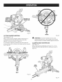
See Figures 32 - 33.
The sliding feature will cut workpieces 11-1/2 in. wide by
3-1/2 in. thick. With the saw off, pull the saw arm forward.
Turn the saw on (let blade reach maximum speed), then
push the blade down on top of the workpiece then back
toward the rear of the saw to make a cut. Cuts are made
by: pushing the saw blade away from you and toward the
bevel scale at the back of the saw stopping when the full
rear position has been reached after each cut. When the
saw is running (turned on), NEVER pull the saw blade toward you or toward the front of the saw.
[] Raise saw arm to its full height.
[] Place the workpiece flat on the miter table with one
edge securely against the fence, if the board is warped,
place the convex side against the fence. If the concave
edge of a board is placed against the fence, the board
Fig. 33
25
[] Withthesawoff,graspthesawhandlefirmlythenpull
thesawforwarduntilthebladearbor(centerofthesaw
blade)is overthefrontoftheworkpiece.
[] Depresstheswitchlockwiththumbthensqueezethe
switchtrigger.Allowseveralsecondsforthe bladeto
reachmaximumspeed.
[] Slowlylowerthe bladeintoandthroughthefrontedge
ofthe workpiece.
[] Pushthesawhandleawayfromyouandtowardthe
bevelscaleatthe backofthesaw.
[] Release
theswitchtriggerandallowthesawblade
to stoprotatingbeforeraisingthebladeoutofthe
workpieceandremovingtheworkpiecefrommiter
table.
NOTE:A crosscutis madebycuttingacrossthegrainof
theworkpiece.
A straightcrosscutis madewiththemiter
tablesetatthe0° position.Mitercrosscutsaremadewith
themitertablesetatsomeangleotherthan0°.
TO MAKE NON-SLIDING
_t_
WARN(NG:
CUTS
CROSSOUT
Fig. 34
Securely tighten the slide lock knob
[] Align cutting line on the workpiece with the edge of
blade.
when making any non-sliding cuts. Failure to tighten
the knob could result in the saw head moving during
the cutting operation.
TO MITER CUT / CROSS
See Figures 34 - 35.
[] Grasp the stock firmly with one hand and secure it
against the fence or use the work clamp or a C-clamp
to secure the workpiece.
CUT
[] Before turning on the saw, perform a dry run of the cutting operation just to make sure that no problems will
occur when the cut is made.
A cross cut is made by cutting across the grain of the
workpiece. A straight cross cut is made with the miter
table set at the 0 ° position. Miter cross cuts are made with
the miter table set at some angle other than zero.
[]
Make sure the slide lock knob is tightened securely.
[]
Pull out the lock pin and lift saw arm to its full height.
[]
Loosen the miter lock handle.
[]
Lift the miter lock plate to disengage.
[]
Rotate the miter table until the pointer aligns with the
desired angle on the miter scale.
[]
Release the miter lock plate.
NOTE: You can quickly locate 0°, 15 °, 22.5 °, 31.6 °, and
45 ° left or right by releasing the lock plate as you rotate
the control arm. The lock plate will seat itself in one of
the positive stop notches, located in the base.
[] Tighten the miter lock handle securely.
[] Place the workpiece flat on the miter table with one edge
securely against the fence. If the board is warped, place
the convex side against the fence. If the concave edge of
a board is placed against the fence, the board could collapse on the blade at the end of the cut, jamming the blade.
1
[] When cutting long pieces of lumber or molding, support the opposite end of the stock with a roller stand
or with a work surface level with the saw table. See
Figure 41.
MITER CUT
Fig. 35
26
[] Graspthesawhandlefirmlythensqueezetheswitch
trigger.Allowseveralsecondsforthebladeto reach
maximumspeed.
[] Slowlylowerthe bladeintoandthroughtheworkpiece.
[] Release
theswitchtriggerandallowthe bladeto stop
rotatingbeforeraisingthebladeout oftheworkpiece.
Waituntiltheelectricbrakestopsbladefromturning
beforeremovingtheworkpiece
fromthe mitertable.
TO BEVEL
CUT
[] Loosen the bevel lock knob and move the saw arm to
the left or right to the desired bevel angle.
NOTE: The bevel stop pin has two positions: 1) override (pin pulled completely out), and 2) the 0 ° - 48 °
position for crown molding (pin pushed in).
[] Bevel angles can be set from 0° to 45 °.
[] Align the indicator point for the desired angle.
[] Once the saw arm has been set at the desired angle,
securely tighten the bevel lock knob.
[] Place the workpiece flat on the miter table with one
edge securely against the fence. If the board is warped,
place the convex side against the fence. If the concave
edge of a board is placed against the fence, the board
could collapse on the blade at the end of the cut, jamming the blade.
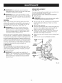
See Figures 36 - 38.
A bevel cut is made by cutting across the grain of the
workpiece with the blade angled to the workpiece. A
straight bevel cut is made with the miter table set at the
zero degree position and the blade set at an angle
between 0 ° and 45 °.
[] When cutting long pieces of lumber or molding,
support the opposite end of the stock with a roller
stand or with a work surface level with the saw table.
[] Unplug the saw.
[] Pull out the lock pin and lift saw arm to its full height.
[] Loosen the miter lock handle.
[] Align the cutting line on the workpiece with the edge of
saw blade.
[] Lift the miter lock plate to disengage.
[] Grasp the stock firmly with one hand and secure it
against the fence or use the work clamp or a C-clamp
to secure the workpiece.
[] Rotate the miter table until the pointer aligns with zero
on the miter scale.
[] Release the miter lock plate.
[] Plug the saw into the power source. Before turning on
the saw, perform a dry run of the cutting operation just
to make sure that no problems will occur when the cut
is made.
NOTE: You can quickly locate zero by releasing the
lock plate as you rotate the control arm. The lock
plate will seat itself in one of the built-in positive
stop notches, located in the base.
[] Grasp the saw handle firmly then squeeze the switch
trigger. Allow several seconds for the blade to reach
maximum speed.
[] Tighten the miter lock handle securely.
[] Adjustments of the miter fence must be made to correspond to the desired angle of the bevel cut prior to
tilting the saw arm. The fence is marked for 0°, 15 °,
30 °, or 45 ° . Loosen the fence screw on the miter fence,
slide the fence to the desired position, and retighten
the fence screw.
[] Slowly lower the blade into and through the workpiece.
[] The 45 ° triangle on the miter fence provides for the
maximum clearance required for adjusting the miter
saw's angle when making a bevel or compound cut.
INDICATORS
FENCE
SCREW
BEVEL
LOCK
KNOB
BEVELSTOP
PiN
Fig. 36
BEVELCUT
27
Fig. 37
[]
Release the switch trigger and allow the saw blade
to stop rotating before raising the blade out of the
workpiece. Wait until the electric brake stops blade
from turning before removing the workpiece from miter
table.
[] Retighten the miter lock handle securely.
[] Adjustments of the miter fence must be made to correspond to the desired angle of the bevel cut prior to
tilting the saw arm. The fence is marked for 0°, 15 °,
30 °, or 45 ° . Loosen the fence screw on the miter fence,
slide the fence to the desired position, and retighten
the fence screw.
[] The 45 ° triangle on the miter fence provides for the
maximum clearance required for adjusting the miter
saw's angle when making a bevel or compound cut.
[] Loosen the bevel lock knob and move the saw arm to
the left or right to the desired bevel angle.
[] Bevel angles can be set from 0° to 45 °.
[] Once the saw arm has been set at the desired angle,
securely tighten the bevel lock knob.
[] Recheck miter angle setting. Make a test cut in scrap
material.
BEVEL
STOPPiN
[] Place the workpiece flat on the miter table with one
edge securely against the fence. If the board is warped,
place the convex side against the fence. If the concave
edge of a board is placed against the fence, the board
could collapse on the blade at the end of the cut, jamming the blade.
[] When cutting long pieces of lumber or molding, support the opposite end of the stock with a roller stand or
with a work surface level with the saw table.
Fig. 38
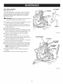
TO COMPOUND
MITER
CUT
A compound miter cut is a cut made using a miter angle
and a bevel angle at the same time. This type of cut is
used to make picture frames, cut molding, make boxes
with sloping sides, and for certain roof framing cuts.
To make this type of cut the control arm on the miter table
must be rotated to the correct angle and the saw arm
must be tilted to the correct bevel angle. Care should
always be taken when making compound miter setups
due to the interaction of the two angle settings.
[] Align the cutting line on the workpiece with the edge of
saw blade.
[] Grasp the stock firmly with one hand and secure it
against the fence or use the work clamp or a C-clamp
to secure the workpiece when possible.
Adjustments of miter and bevel settings are interdependent with one another. Each time you adjust the miter
setting you change the effect of the bevel setting. Also,
each time you adjust the bevel setting you change the
effect of the miter setting.
It may take several settings to obtain the desired cut. The
first angle setting should be checked after setting the
second angle, since adjusting the second angle affects
the first.
Once the two correct settings for a particular cut have
been obtained, always make a test cut in scrap material
before making a finish cut in good material.
[] Pull out the lock pin and lift saw arm to its full height.
[] Loosen the miter lock handle.
[] Lift the miter lock plate to disengage.
[] Rotate the miter table until the pointer aligns with the
desired angle on the miter scale.
[] Release the miter lock plate.
NOTE: You can quickly locate 0°, 15 °, 22.5 °, 31.6 °, and
45 ° left or right by releasing the miter lock plate as you
rotate the control arm. The miter lock plate will seat
itself in one of the positive stop notches, located in the
base.
COMPOUNDMITER CUT
Fig. 39
28
[] Beforeturningonthe saw,performa dryrunofthecuttingoperationjustto makesurethatnoproblemswill
occurwhenthecutis made.
[] Graspthesawhandlefirmlythensqueezetheswitch
trigger.Allowseveralsecondsforthebladeto reach
maximumspeed.
[] Slowlylowerthe bladeintoandthroughtheworkpiece.
[] Release
theswitchtriggerandallowthe bladeto stop
rotatingbeforeraisingthebladeout oftheworkpiece.
Waituntiltheelectricbrakestopsbladefromturning
beforeremovingtheworkpiece
frommitertable.
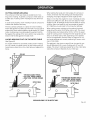
SUPPORTLONG WORKP(ECES
See Figure 38.
Long workpieces need extra supports. Supports should
be placed along the workpiece so it does not sag. The
support should let the workpiece lay flat on the base of
the saw and work table during the cutting operation. Use
the work clamp or a C-clamp to secure the workpiece.
45°X 45° COMPOUNDMITER CUT
Fig. 4O
LONGWORKPIECE
ROLLER
SUPPORT
Fig. 41
29
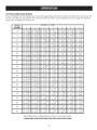
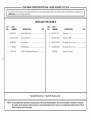
CUTTINGCOMPOUNDMITERS
Toaid in making the correct settings, the
compound angle setting chart below has been provided. Since compound cuts
are the most difficult to accurately obtain, trial cuts should be made in scrap material, and much thought and planning
made, prior to making your required cut.
PITCH
OF SIDE
0o
NUMBER OF SIDES
|
5
J
6
M30.00
°
M- 45.00 ° M- 36.00 °
B0.00
°
B- 0.00 ° B- 0.00 °
1
7
j
8
1
9
1
10
M- 25.71 o
B- 0.00 °
M- 22.50 °
B- 0.00 °
M- 20.00 ° M- 18.00 °
B- 0.00 ° B- 0.00 °
5°
M- 44.89 °
B- 3.53 °
M- 35.90 °
B- 2.94 °
M- 29.91 o
B- 2.50 °
M- 25.63 °
B- 2.17 °
M- 22.42 °
B- 1.91°
M- 19.93 °
B- 1.71°
M- 17.94 °
B- 1.54 °
10 °
M- 44.56 °
B- 7.05 °
M- 35.58 °
B- 5.86 °
M- 29.62 °
B- 4.98 °
M- 25.37 °
B- 4.32 °
M- 22.19 °
B- 3.81 o
M- 19.72 °
B- 3.40 °
M- 17.74 °
B- 3.08 °
15 °
M- 44.01 o M- 35.06 °
B- 10.55 ° B- 8.75 °
M- 29.15 °
B- 7.44 °
M- 24.95 °
B- 6.45 °
M- 21.81 o M- 19.37 °
B- 5.68 ° B- 5.08 °
M- 17.42 °
B- 4.59 °
20 °
M- 43.22 °
B- 14.00 °
M- 34.32 °
B- 11.60 °
M- 28.48 °
B- 9.85 °
M- 24.35 °
B- 8.53 °
M- 21.27 °
B- 7.52 °
M- 18.88 °
B- 6.72 °
M- 16.98 °
B- 6.07 °
25 °
M- 42.19 °
B- 17.39 °
M- 33.36 °
B- 14.38 °
M- 27.62 °
B- 12.20 °
M- 23.56 °
B- 10.57 °
M- 20.58 °
B- 9.31 o
M- 18.26 °
B- 8.31 o
M- 16.41 °
B- 7.50 °
30 °
M- 40.89 °
B- 20.70 °
M- 32.18 °
B- 17.09 °
M- 26.57 °
B- 14.48 °
M- 22.64 °
B- 12.53 °
M- 19.73 °
B- 11.03 °
M- 17.50 °
B- 9.85 °
M- 15.72 °
B- 8.89 °
35 °
M- 39.32 °
B- 23.93 °
M- 30.76 °
B- 19.70 °
M- 25.31 o
B- 16.67 °
M- 21.53 °
B- 14.41 °
M- 18.74 °
B- 12.68 °
M- 16.60 °
B- 11.31 °
M- 14.90 °
B- 10.21 °
40 °
M- 37.45 °
B- 27.03 °
M- 29.10 °
B- 22.20 °
M- 23.86 °
B- 18.75 °
M- 20.25 °
B- 16.19 °
M- 17.60 °
B- 14.24 °
M- 15.58 °
B- 12.70 °
M- 13.98 °
B- 11.46 °
45 °
M- 35.26 °
B- 30.00 °
M- 27.19 °
B- 24.56 °
M- 22.21 o
B- 20.70 °
M- 18.80 °
B- 17.87 °
M- 16.32 °
B- 15.70 °
M- 14.43 °
B- 14.00 °
M- 12.94 °
B- 12.62 °
50 °
M- 32.73 °
B- 32.80 °
M- 25.03 °
B- 26.76 °
M- 20.36 °
B- 22.52 °
M- 17.20 °
B- 19.41 °
M- 14.91 °
B- 17.05 °
M- 13.17 °
B- 15.19 °
M- 11.80 °
B- 13.69 °
55 °
M- 29.84 °
B- 35.40 °
M- 22.62 °
B- 28.78 °
M- 18.32 °
B- 24.18 °
M- 15.44 °
B- 20.82 °
M- 13.36 °
B- 18.27 °
M- 11.79 °
B- 16.27 °
M- 10.56 °
B- 14.66 °
60 °
M- 26.57 °
B- 37.76 °
M- 19.96 °
B- 30.60 °
M- 16.10 °
B- 25.66 °
M- 13.54 °
B- 22.07 °
M- 11.70 °
B- 19.35 °
M- 10.31 °
B- 17.23 °
M- 9.23 °
B- 15.52 °
65 °
M- 22.91 o M- 17.07 °
B- 39.86 ° B- 32.19 °
M- 13.71 °
B- 26.95 °
M- 11.50 °
B- 23.16 °
M- 9.93 °
B- 20.29 °
M- 8.74 °
B- 18.06 °
M- 7.82 °
B -16.26 °
70 °
M- 18.88 °
B- 41.64 °
M- 13.95 °
B- 33.53 °
M- 11.17 °
B- 28.02 °
M- 9.35 °
B- 24.06 °
M- 8.06 °
B- 21.08 °
M- 7.10 °
B- 18.75 °
M- 6.34 °
B- 16.88 °
75 °
M- 14.51 °
B- 43.08 °
M- 10.65 °
B- 34.59 °
M- 8.50 °
B- 28.88 °
M- 7.10 °
B- 24.78 °
M- 6.12 °
B- 21.69 °
M- 5.38 °
B- 19.29 °
M- 4.81 o
B- 17.37 °
80 °
M- 9.85 °
B- 44.14 °
M- 7.19 °
B- 35.37 °
M- 5.73 °
B- 29.50 °
M- 4.78 °
B- 25.30 °
M- 4.11 °
B- 22.14 °
M- 3.62 °
B- 19.68 °
M- 3.23 °
B- 17.72 °
85 °
M- 4.98 °
B- 44.78 °
M- 3.62 °
B- 35.84 °
M- 2.88 °
B- 29.87 °
M- 2.40 °
B- 25.61 o
M- 2.07 °
B- 22.41 o
M- 1.82 °
B- 19.92 °
M- 1.62 °
B- 17.93 °
90 °
M- 0.00 °
B- 45.00 °
M- 0.00 °
B- 36.00 °
M- 0.00 °
B- 30.00 °
M- 0.00 °
B- 25.71 o
M- 0.00 °
B- 22.50 °
M- 0.00 °
B- 20.00 °
M- 0.00 °
B- 18.00 °
Each B (Bevel) and M (Miter) Setting is Given to the Closest 0.005 °.
COMPOUND=ANGLE SETTINGS FOR POPULAR STRUCTURES
3O
CUTTINGCROWNMOLDING
When setting the bevel and miter angles for compound
miters, remember that the settings are interdependent;
changing one angle changes the other angle as well.
The compound miter saw does an excellent job of cutting crown molding. In general, compound miter saws do
a better job of cutting crown molding than any other tool
made.
Keep in mind that the angles for crown moldings are very
precise and difficult to set. Since it is very easy for these
angles to shift, all settings should first be tested on scrap
molding. Also most walls do not have angles of exactly
90, therefore, you will need to fine tune your settings.
In order to fit properly, crown molding must be compound
mitered with extreme accuracy.
The two contact surfaces on a piece of crown molding
that fit fiat against the ceiling and the wall of a room are at
angles that, when added together, equal exactly 90°. Most
crown molding has a top rear angle (the section that fits
fiat against the ceiling) of 52 ° and a bottom rear angle (the
section that fits fiat against the wall) of 38 °.
LAYING MOLDING
See Figure 42.
FLAT ON THE MITER
When cutting crown molding by this method the bevel
angle should be set at 33.9 ° either right or left. The crown
molding stops are marked either 33.9°or 45°for the exact
angle for cutting crown molding.The miter angle should be
set at 31.6 ° either right or left, depending on the desired
cut for the application. See the chart on page 32 for correct angle settings and correct positioning of crown molding on miter table.
TABLE
The settings in the chart on page 32 can be used for cutting All Standard (U.S.) crown molding with 52 ° and 38 °
angles. The crown molding is placed fiat on the miter table
using the compound features of your miter saw.
To use this method for accurately cutting crown molding
for a 90 ° inside or outside corner, lay the molding with its
broad back surface flat on the miter table and against the
fence.
52°
CEILING
38°
L
INSIDE
CORNER
FENCE
TOP EDGEAGAINSTFENCE=
® LEFTSIDE, INSIDE CORNER
e RIGHTSIDE, OUTSIDECORNER
FENCE
BOTTOMEDGEAGAINSTFENCE=
• RIGHTSIDE, iNSiDE CORNER
®LEFTSIDE, OUTSIDECORNER
MITERTABLE
0
OUTSIDE
CORNER
MITERTABLE
0
CROWNMOLDINGFLATONMITER TABLE
Fig. 42
31
Bevel
Angle
[] Loosen the crown molding stop by turning the knob
counterclockwise.
Type of Cut
[] Place the stop in the hole on either the left or the right
side of the saw's base. See figure 43.
Setting
33.85 ':=
Left side, inside corner
1. Top edge of molding against fence
2. Miter table set right 31.62 °
3. Save left end of cut
33.85:
Right side, inside corner
1. Bottom edge of molding against fence
2. Miter table set left 31.62 °
3. Save left end of cut
33.85:
33.85:
CUTTING
[] With the bottom of the molding (wall side) against the
miter fence and the top of the molding (ceiling side)
against the miter table, align with the desired mark on
the throat plate then spin the crown molding stop until
it fits snuggly against the crown molding.
[] Secure the crown molding stop in place by turning the
knob clockwise.
[] Hold the crown molding in place with your hand (the
side not secured with the stop).
NOTE: NEVER place your hand inside the "No Hands"
zone while the saw is on.
Left side, outside corner
1. Bottom edge of molding against fence
2. Miter table set left 31.62 °
3. Save right end of cut
[] Grasp the saw handle firmly then squeeze the switch
trigger. Allow several seconds for the blade to reach
maximum speed.
Right side, outside corner
1. Top edge of molding against fence
2. Miter table set right 31.62 °
3. Save right end of cut
MOLDING
USING
THE CROWN
[] Slowly lower the blade into and through the workpiece.
[] Release the switch trigger and allow the blade to stop
rotating before raising the blade out of workpiece. Wait
until the electric brake stops blade from turning before
removing the workpiece from miter table.
MOLD=
ING STOP
See Figures 43 - 44.
CROWN
MOLDING
STOP
To use this method for accurately cutting crown molding
for a 90° inside or outside corner, place the crown molding
upside down on the miter table.
Keep in mind that the angles for crown moldings are very
precise and difficult to set. Since it is very easy for these
angles to shift, all settings should first be tested on scrap
molding. Also most walls do not have angles of exactly
90°, therefore, you will need to fine tune your settings.
KNOB
When cutting crown molding by this method the bevel
angle should be set at 0°. The miter angle should be set at
45 ° either right or left, depending on the desired cut for the
application.
Using the markings on the throat plate, you can accurately
cut All Standard (U.S.) with 52° and 38°angles in sizes
of 2-3/4 in., 3-5/8 in., 4-5/8 in., and 5-1/4. You cannot
use the markings on the throat plate when cutting crown
molding with 45 ° and 45°angles.
Fig. 43
32
MARKINGSON
THROATPLATE
Fig. 44
WRONG
CUTTING
WARPED
Fig. 46
MATERIAL
A
See Figures 45 - 46.
When cutting warped material, always make sure it is
positioned on the miter table with the convex side
against the fence as shown in figure 45.
WARNING:
To avoid a kickback and to avoid
serious personal injury, never position the concave
edge of bowed or warped material against the fence.
If the warped material is positioned the wrong way as
shown in figure 46, it will pinch the blade near the completion of the cut.
CLAMPING
WIDE WORKPIECES
See Figure 47.
When cutting wide workpieces such as a 2 in. x 12 in.,
boards should be clamped with a C-clamp as shown in
figure 47.
RIGHT
Fig. 45
Fig. 47
33
A
A
BRUSH REPLACEMENT
See Figure 48.
WARNING:
When servicing, use only identical
replacement parts. Use of any other part may create
a hazard or cause product damage.
Your saw has externally accessible brush assemblies that
should be periodically checked for wear.
Proceed as follows when replacement is required:
WARNING:
Always wear safety goggles or safety
glasses with side shields during power tool operation
or when blowing dust. If operation is dusty, also wear
a dust mask.
[] Unplug the saw.
_1_ WARNING:
Failure to unplug the saw could result in
accidental starting causing serious injury.
GENERAL
[] Remove brush cap with a screwdriver. Brush assembly
is spring loaded and will pop out when you remove
brush cap.
[] Remove brush assembly.
[] Check for wear. Replace both brushes when either has
less than 1/4 in. length of carbon remaining. Do not
replace one side without replacing the other.
[] Reassemble using new brush assemblies. Make sure
curvature of brush matches curvature of motor and
that brush moves freely in brush tube.
[] Make sure brush cap is oriented correctly (straight) and
replace.
[] Tighten brush cap securely. Do not overtighten.
Avoid using solvents when cleaning plastic parts. Most
plastics are susceptible to damage from various types of
commercial solvents and may be damaged by their use.
Use clean cloths to remove dirt, carbon dust, etc.
,_
WARNING:
Do not at any time let brake fluids,
gasoline, petroleum-based products, penetrating
oils, etc. come in contact with plastic parts. Chemicals can damage, weaken or destroy plastic which
may result in serious personal injury.
Electric tools used on fiberglass material, wallboard, spackling compounds, or plaster are subject to accelerated wear
and possible premature failure because the fiberglass chips
and grindings are highly abrasive to bearings, brushes, commutators, etc. Consequently, we do not recommend using
this tool for extended work on these types of materials. However, if you do work with any of these materials, it is extremely
important to clean the tool using compressed air.
BRUSH_
CAP_,
BRUSH/
ASSEMBLY
LUBRICATION
All of the bearings in this tool are lubricated with a sufficient amount of high grade lubricant for the life of the unit
under normal operating conditions. Therefore, no further
lubrication is required.
_IL
BRUSH
ASSEMBLY
WARNING:
To ensure safety and reliability, all
repairs -- with the exception of the externally accessible brushes -- should be performed by a qualified
service technician at a Sears store to avoid risk of
personal injury.
!
BRUSH
CAP
Fig. 48
34
BELTREPLACEMENT
BELTCOVER
See Figures 49 - 50,
HOUSING
The saw is powered by a belt-driven motor. Periodically
check the belt for wear and replace it when necessary.
Proceed as follows when replacement is required:
[] Unplug the saw.
WARNING:
Failure to unplug the saw could result in
accidental starting causing serious injury.
-7
[] Pull saw arm all the way down and engage the lock pin
to hold the saw arm in transport position.
[] Using a phillips screwdriver, remove the screws from
the belt cover. Carefully lift the belt cover off the housing and set aside.
[] Loosen the adjustment screws.
[] Loosen the set screw on the motor housing. Push the
motor housing down until there is enough slack in the
belt for it to be removed from around the pulleys.
[] Place the new belt (grooves turned to the inside)
around the bottom pulley.
[] Push the motor housing down with one hand while
pulling the belt up and over the second pulley with the
other hand. Release the motor housing.
[] Turn the belt by hand until you are certain it is properly
aligned on the grooves of the pulleys.
[] Lift the motor housing up and retighten the set screw.
[] Check belt tension by squeezing the belt. Using light
pressure, the belt should deflect approximately 1/4 in.
NOTE: If belt tension is not correct, adjust the set
screw until tension is correct.
SCREWS
Fig. 49
MOTOR HOUSING
SETSCREW
ADJUSTMENT
SCREWS
ADJUSTMENT
[] Once belt tension is correct, retighten adjustment
screws.
[] Reinstall the belt cover with the phillips screws.
BELT
Fig. 50
35
CHANGINGTHE
BATTERIES
See Figure 51.
[] Unplug the saw.
[] Rotate and hold lower blade guard up.
[] Using the hex key (1/16 in.) provided, loosen and
remove the screw from the battery cover then separate
the cover from the laser guide. Lower the blade guard.
SCREW
[] Remove the three button cell batteries.
BATTERY
COVER
NOTE: Replace the batteries with button cell batteries
that have a rating of 1.5 volt and 100 mAh (milliampere
hour) minimum (number 76 series or equivalent).
When replacing the batteries, the laser guide should be
thoroughly cleaned. Use a soft paintbrush, or similar
device, to remove all sawdust and debris.
[] After cleaning the laser guide and replacing batteries,
secure battery cover to laser guide using the screw.
Tighten screw securely.
CAUTION:
BATTERIES
BATTERY
COVER
Use of controls or adjustments or per-
formance of procedures other than those specified
herein may result in hazardous radiation exposure.
NEGAT(VE(-)
Fig. 51
36
ADJUSTING
THE LASER GUIDE
See Figure 52.
NOTE: Avoid direct eye exposure when using the laser
guide.
ADJUSTMENT
SCREW
[] Set both the bevel angle and the miter table at 0°.
[] Use the optional work clamp or a C-clamp to secure a
piece of scrap wood.
APERTURE
[] Plug the saw into the power source and make a slight
cut to score the wood.
[] Raise the saw arm and unplug the saw.
[] Lift and hold the lower blade guard.
[] Loosen the phillips screw on the blade bolt cover until
the cover can be raised.
LASER
BUTTON
[] Gently raise the lower blade guard bracket so that
lower blade guard and blade bolt cover can be rotated
up and back to expose the laser.
REX KEY
[] Rotate the blade by hand until you can push and hold
the laser button and the laser is near the center of the
workpiece as shown in figure 52.
[] To adjust the laser, turn the adjustment screw counterclockwise or clockwise using the hex key (1/16 in.)
provided.
NOTE: When properly aligned, the laser should be on
the left edge of the kerf.
[] Once aligned, remove and store the hex key (1/16 in.),
and lower the blade guard.
LASER
MARK
[] Replace the lower blade guard and blade bolt cover.
[] Retighten the phillips screw securing the blade bolt
cover.
NOTE: Always make practice cuts on scrap wood before
cutting through your workpiece.
Fig. 52
37
CRAFTSMAN
5
COMPOUND
MITER SAW - MODEL
5
8
NUMBER
315.212010
6
12
7
4 11
10
j/
\
32
33
\
\
.--"'""
41
/
1
/
/
Figure A
40
_-
CRAFTSMAN
COMPOUND
MITER SAW - MODEL
NUMBER
315.315.212010
The
model
number
will ordering
be found repair
on a plate
MITER
SAW
or when
parts. attached to the motor housing. Always mention the model number in all correspondence
regarding your
J
1
PARTS LIST FOR FIGURE A
KEY
NO.
1
2
3
4
5
6
7
8
9
10
11
12
13
14
15
16
17
18
19
20
21
22
23
24
25
26
27
28
29
30
PART
NUMBER
089100110067
089100110071
089100110069
089100110070
A07103080457
A07003080208
A36030814204
A16003040083
089100110061
089100110062
089100110063
089100110068
089100110059
089100110029
089100110030
089100110031
089100110020
089100110901
A10003050105
A35010510010
089100110026
089100110024
A10003060103
089100110251
089100110022
A31703008000
089100110019
A49010020056
089100110018
089100110015
DESCRIPTION
QTY.
Fence, Base .....................................................
Warning Label (Sliding Fence) .........................
Slide Fence (left, Incl. Key No. 2) .....................
T-Bolt, Slide Fence ..........................................
* Screw (M8 x 45 mm, Hex Soc. Hd.) ................
* Screw (M8 x 20 mm, Hex Hd.) .........................
Spring Washer (M8) .........................................
* Screw (M4 x 8 mm, Flat Hd.) ...........................
Fence Screw Lever ..........................................
1
2
1
2
2
2
4
2
2
Spring ..............................................................
Pivot .................................................................
Screw (M4 x 5 mm, Hex Soc. Hd.) ..................
Slide Fence (right, Incl. Key No. 2) ..................
Release Knob ..................................................
Spring ..............................................................
Spacer .............................................................
E-Ring ..............................................................
Label, Micro Adjust ..........................................
* Screw (M5 x 10 mm, Pan Hd.) .........................
* Washer (5 x 10 x lt) .........................................
Miter Indicator .................................................
Throat Plate .....................................................
* Screw (M6 x 10 mm, Pan Hd.) .........................
Washer (D8.2 x D20 x 1.5T) .............................
Washer (D25 x D10 x 1.5T) ..............................
Lock Nut (M8) ..................................................
Bevel Stop Pin Lever .......................................
* Rivet (2.5 x 5 mm) ............................................
Bevel Scale ......................................................
Bevel Lock Pin .................................................
2
2
2
1
1
1
1
2
1
1
1
1
1
6
1
1
1
1
2
1
1
*
KEY
NO.
PART
NUMBER
31
32
33
34
35
36
37
38
39
40
41
42
43
44
45
46
47
48
49
50
51
52
53
54
55
56
57
58
59
089100110016
089100110007
089100110025
089100110014
089100110013
545407000
089100110036
089100110048
089100110047
089100110046
089100110045
089100110044
089100110713
089100110043
089100110042
089100110035
089100110057
089100110032
089100110041
089100110254
A36030407016
089100110038
089100110039
089100110040
089100110012
089100110037
089100110034
089100110033
089100110900
60
089100110701
DESCRIPTION
*
*
*
*
*
*
Standard Hardware Item = May Be Purchased Locally
QTY.
Spring, Bevel Lock Pin ....................................
Warning Label (No Hands) ...............................
Table (Inc. Key Nos. 28-29) .............................
Spring, Foot .....................................................
Leveler .............................................................
Screw (M5 x 12 mm) ........................................
Screw (M4 x 25 mm, Hex Soc. Hd.) ................
E-Ring ..............................................................
Spring ..............................................................
Shaft ................................................................
Lever ................................................................
Miter Quick Lock Pin .......................................
Miter Knob Lock Pin Assembly .......................
C-Ring .............................................................
Knob, Fine Miter Adjustment ...........................
Spring, Fine Miter Adjustment .........................
Coupling ..........................................................
Set Screw (M4 x 6 mm, Nylock) .....................
Pipe ..................................................................
Screw (M4 x 4 mm) ..........................................
Spring Washer (M4) .........................................
E-Ring ..............................................................
Spring ..............................................................
Flat Washer (14 x 20 x lt) ................................
Flat Washer (14 x 19 x 2.5t) .............................
Pinion ...............................................................
Block, Miter Lock .............................................
Plate, Miter Lock ..............................................
Knob Label ......................................................
1
2
1
1
1
2
2
1
1
1
1
1
1
1
1
1
1
1
1
1
1
1
1
1
1
1
1
1
1
Table Assembly
(Incl. Key Nos. 14-42, 44-59) ...........................
1
€
CRAFTSMAN
COMPOUND
MITER SAW - MODEL
NUMBER
315.212010
-_
/
3
\
/
/
/
\
\
\
\
\
j-f
<_
/
/
"_.
/
i
/
/
o_
I
/
I
31
I
30
.
t
I
/
I
I
1
.._
\
Figure
B
/
/
"_"
*
CRAFTSMAN
COMPOUND
MITER SAW - MODEL
NUMBER
315.212010
The model
MITER
SAW
number
or when
will ordering
be found repair
on a parts.
plate attached to the motor housing. Always mention the model number in all correspondence
J
regarding your
|
PARTS LIST FOR FIGURE B
KEY
NO.
1
PART
NUMBER
089100110800
2
A42001060300
3
4
5
6
7
8
9
10
11
701106000
701107000
545503000
A10003060158
503511000
A35031020300
503507000
089100110212
089100110700
12
13
14
089100110049
089100110001
089100110002
15
16
17
18
19
20
21
22
23
089100110004
089100110003
089100110007
565109000
089100110005
A49010020056
503121000
503118000
565A07020
DESCRI PTION
QTY.
Work Clamp Assembly
(Incl. Key Nos. 2-10) .......................................
Quick Release Pin ...........................................
1
1
Quick Release .................................................
1
Torsion Spring .................................................
Work Clamp Base ...........................................
*Screw (M6 x 15 mm, Pan Hd.) .......................
Clamp Plate ....................................................
*Flat Washer (10 x 20 x 3t) ...............................
Spindle ............................................................
Work Clamp Knob ...........................................
1
1
1
1
1
1
1
Base Assembly
(Incl. Key Nos. 12-22) .....................................
Wear Ring .......................................................
Base ................................................................
1
1
1
Table Spindle ..................................................
Screw (Hex Soc. Hd.) ......................................
Miter Lock Plate ..............................................
1
3
1
Hand Warning Label .......................................
Line Label .......................................................
Miter Scale ......................................................
Rivet ................................................................
2
2
1
3
***Hex Key (5 mm) ..............................................
Grommet .........................................................
1
1
Crown Molding Stop Assembly
(Incl. Key Nos. 24-29) ...................................
*
***
1
KEY
NO.
PART
NUMBER
24
25
26
27
28
29
30
565507000
A35010823020
565504000
A18003040080
565505000
565506000
A07910420000
31
32
33
089100110229
089100110258
089100110804
34
35
36
37
38
39
545512000
558507200
558512100
558511100
555516000
545A07030
40
41
42
545508000
545506000
545507000
43
44
45
46
47
A33055056000
545509000
A10003040050
545511000
545505000
DESCRIPTION
QTY.
Crown Molding Knob ......................................
* Flat Washer (8 x 23 x 2t) .................................
Crown Molding Clamp ....................................
1
1
1
*Set Screw (M4 x 8 mm) ..................................
Upper Tube, Adjustable ..................................
1
1
Lower Tube, Adjustable ..................................
Hex Key (4 mm) ..............................................
Hex Key (6 mm) ...............................................
Hex Key (8 mm) ..............................................
Roller Support Assembly
(Incl. Key Nos. 34-47) .....................................
Table Extension ...............................................
1
1
1
1
1
2
Stop Block ......................................................
Wing Screw .....................................................
Clamp Bracket ................................................
Wing Screw .....................................................
Roller Base Assembly
(Incl. Key Nos. 40-47) .....................................
Roller ...............................................................
1
1
1
1
Roller Support Front Brace .............................
Roller Base ......................................................
1
1
*Wing Nut (5/16 in.) ..........................................
Adjustable Bolt (5/16 in.).................................
Screw (M4 x 5 mm, Pan Hd.) ..........................
* Wing Screw (M8 x 20 mm) ..............................
Roller Support End Brace ...............................
1
1
4
1
1
Standard Hardware Item = May Be Purchased Locally
Available At Your Nearest Sears Catalog Order or Retail Store
1
1
r"
CRAFTSMAN
26
-
t
/
27
11
Figure C
39
COMPOUND
MITER SAW - MODEL
NUMBER
315.212010
"_
_-
CRAFTSMAN
i
COMPOUND
MITER SAW - MODEL
NUMBER
315.212010
The model
number
will ordering
be found repair
on a parts.
plate attached to the motor housing. Always mention the model number in all correspondence
MITER
SAW
or when
}
regarding your
PARTS LIST FOR FIGURE C
KEY
NO.
PART
NUMBER
DESCRIPTION
QTY.
KEY
NO.
PART
NUMBER
DESCRIPTION
QTY.
089100110704
Pivot & Pivot Support Assembly
(Incl. Key Nos. 2-16, 18-25) ......................... 1
20
A35010510010
Washer (5 x 10 x lt) .....................................
21
A10003050105
Screw (M5 x 10 mm, Pan Hd.) ..................... 2
2
089100110090
Pivot Bracket, Bevel ...................................
1
22
089100110088
Bevel Lock Plate ..........................................
1
3
089100110091
Set Screw (M8 x 18 mm) .............................
4
23
089100110249
Spring ..........................................................
2
4
A30003008001
* Hex Nut (M8) ................................................
4
24
089100110085
Screw (M6 x 12 mm, Flat Hex Socket Hd.).2
5
089100110093
Fixed Screw, Rail .........................................
1
25
089100110089
Bevel Indicator (left) .....................................
6
089100110098
Spacer, Rail Cover .......................................
4
26
089100110703
7
089100110099
Linear Bearing .............................................
2
Pivot Bracket Bevel Assembly
(Incl. Key Nos. 11 and 27-39) ...................... 1
8
089100110100
Dust Seal .....................................................
4
27
089100110084
Slide Rail A ..................................................
1
9
089100110101
Plate, Rail Cover ..........................................
2
28
089100110083
Slide Rail B ..................................................
1
10
089100110102
Bumper, Rail ................................................
2
29
089100110082
Grommet ......................................................
1
11
089100110105
Set Screw (M8 x 10 mm, Nylock) ................ 4
30
545209000
Stop Pin Cap ...............................................
1
12
089100110106
Strain Relief .................................................
1
31
089100110074
Pin, Spring ...................................................
1
13
089100110104
Rear Cap, Rail ..............................................
1
32
089100110076
Block, Groove Set Up ..................................
1
14
A10003050120
* Screw (M5 x 12 mm, Pan Hd.) ..................... 2
33
089100110077
Bolt, Groove Set Up ....................................
1
15
089100110097
Screw (M10 x 48 mm
Hex Socket Hd., Trilobular) .......................... 1
34
089100110072
Steel Ball ......................................................
1
35
089100110073
Spring ..........................................................
1
16
089100110094
Wavy Washer ...............................................
2
36
089100110078
Pivot Shaft ...................................................
1
17
089100110096
Bevel Lock Knob .........................................
1
37
089100110081
Pin, Fixed .....................................................
1
18
A35030401008
.....................................
1
38
A63000000051
O-Ring
1
19
089100110087
Bevel Indicator (right) ...................................
1
39
089100110075
Pivot Bracket, Guard ...................................
* Washer (4xl0xlt)
* Standard Hardware Item -- May Be Purchased Locally
........................................................
2
1
1
CRAFTSMAN
COMPOUND
MITER SAW - MODEL
NUMBER
315.212010
%`
%`
'%,
15
%"
%`
%`
%`
12
%`
%`
7
%`
\
8
18
I
I
I
I
/
%`
J
%`
f
,%.
J
%`
%`
f
%`
J
%"
f
%`
f
%`
f
%`
f
%`
f
f
Figure D
CRAFTSMAN
I
COMPOUND
MITER SAW - MODEL
NUMBER
315.212010
The model
number
will ordering
be found repair
on a parts.
plate attached to the motor housing. Always mention the model number in all correspondence
MITER
SAW
or when
J
regarding your 1
PARTS LIST FOR FIGURE D
KEY
NO.
PART
NUMBER
089100110709
DESCRIPTION
QTY.
KEY
NO.
PART
NUMBER
DESCRIPTION
QTY.
10
A45204040080
Parallel Key (4 x 4 x 8) .....................................
1
1
11
545309000
Master Gear .....................................................
1
* Screw (M6 x 15 mm, Pan Hd.) ......................... 3
Bearing Plate ...................................................
1
Gear Case Assembly
(Incl. Key Nos. 2-17) ........................................
2
A10003060156
12
545310000
3
545306000
Bearing Cover ..................................................
1
13
A10003040066
4
A53010100000
Needle Bearing ................................................
2
14
A50060030041
Ball Bearing (6003Z/RS) ..................................
1
5
545311000
Gear Shaft .......................................................
1
15
545308000
Gear Shaft / Arbor ...........................................
1
6
A46100280000
C-Ring .............................................................
1
16
565306000
Gasket .............................................................
1
7
A50060010050
Ball Bearing (6001 2RS) ...................................
1
17
A63030001260
O-Ring ............................................................
1
8
A63030001220
O-Ring ............................................................
1
18
089100110708
Lower Guard Assembly ...................................
1
9
A46000150008
C-Ring .............................................................
1
* Screw (M4 x 6 mm, Pan Hd. Nylock) ............... 2
* Standard Hardware item = May Be Purchased Locally
CRAFTSMAN
Note: For Laser Guide repair
or replacement, contact your
nearest Sears Service Center
2
COMPOUND
MITER SAW - MODEL
NUMBER
315.212010
--11
\
I
/
/
/
/
i
Figure E
'_
CRAFTSMAN
COMPOUND
MITER SAW - MODEL
NUMBER
315.212010
The model
number
will ordering
be found repair
on a parts.
plate attached to the motor housing. Always mention the model number in all correspondence
MITER
SAW
or when
regarding your
PARTS LIST FOR FIGURE E
KEY
NO.
PART
NUMBER
DESCRIPTION
QTY.
KEY
NO.
PART
NUMBER
DESCRIPTION
QTY.
1
511505000
Laser Guide Bolt ..........................................
1
8
089100110247
Hang Tag (Tip Over) .....................................
1
2
089100300723
Adjustable Laser ..........................................
1
9
A70003060250
Screw (M6 x 25 mm) ....................................
2
3
089100110805
Flange / Arbor Bolt Set ................................
1
10
545328000
Carrying Handle ...........................................
1
4
510502007
Blade ...........................................................
1
11
089100300719
5
588035105
Inner Blade Washer .....................................
1
Adjustable Laser Replacement Kit
(inc. Key Nos. 1-2 and 12-13) ..................... 1
6
538327000
12
089100300726
Spacer .........................................................
2
Hex Key (1/16 in.) ........................................
1
7
089100110107
13
089100300727
Torsion Spring ..............................................
1
Warning Label ..............................................
1
14
089100110707
Upper Guard Assembly ...............................
1
* Standard Hardware Item -- May Be Purchased Locally
*** Complete Assortment Available At Your Nearest Sears Catalog Order or Retail Store
NOTE:
The assembly shown represents an important part of the Double Insulated System. To avoid the possibility of alteration or damage
to the system, service should be performed by your nearest Sears Repair Center. Contact your nearest Sears Catalog Order or Retail
Store for Service Center Information.
_,
CRAFTSMAN
COMPOUND
MITER SAW - MODEL
NUMBER
315.212010
,_
23
2
3
27
]
28
7
3O
18
32
10
_-
CRAFTSMAN
I
COMPOUND
MITER SAW - MODEL
NUMBER
315.212010
The
model
number
will ordering
be found repair
on a plate
MITER
SAW
or when
parts. attached to the motor housing. Always mention the model number in all correspondence
-_
J
regarding your
l
PARTS LIST FOR FIGURE F
KEY
NO.
PART
NUMBER
1
08910011 0221
2
A07203060200
DESCRIPTION
QTY.
Dust Bag ...................................................
*
Screw w/Washer (M6 x 20 mm,
Hex Socket Hd.) .......................................
1
2
KEY
NO.
PART
NUMBER
DESCRI PTION
QTY.
18
545305000
Lock Pin Plate .........................................
1
19
089100110113
Arbor Lock Pin .........................................
1
20
545303000
Compression Spring ................................
1
21
545304000
Felt Washer (6 x 10 x 2t) ..........................
1
22
089100110121
Label, Belt Cover .....................................
1
23
545329000
Logo Label ..............................................
1
24
089100110132
Upper Guard ............................................
1
25
E07010000450
Sleeve ......................................................
1
26
545501000
Dust Guide ..............................................
1
27
089100110705
Dust Chute Assembly
(Incl. Key Nos. 28-31) ...............................
1
3
089100110146
Screw (Hex Socket Hd.) ........................... 2
4
545320000
Belt ...........................................................
5
A10003050180
6
545321000
Belt Cover .................................................
1
7
089100110159
Logo Label ...............................................
1
8
A16003050100
9
089100110139
Cavity (Plastic Cover) ...............................
10
A10003050105
Screw (M5 x 10 mm, Pan Hd.) ................. 2
11
E07000846157
Cord Clamp ..............................................
1
28
089100110116
Dust Collector ..........................................
1
12
089100110137
Screw, Groove Set Up ..............................
1
29
089100110110
Pin, Dust Chute ........................................
1
13
089100110136
Spring .......................................................
1
30
089100110109
Dust Chute ...............................................
1
14
A07013050150
*
Screw (M5 x 15 mm, Hex Socket Hd.) ..... 1
31
A19003050120
Screw (M5 x 12 mm, Pan Hd.) ................. 1
15
A35010519150
* Washer (5 x 19 x 1.5t) ...............................
1
32
089100110111
Screw (M5 x 15 mm, Pan Hd.) ................. 2
16
A45204040080
Parallel Key (4 x 4 x 8) ..............................
1
33
089100110706
17
545312000
Arbor Pulley ..............................................
1
Upper Arm Assembly
(Incl. Key Nos. 2-26) .................................
*
*
1
Screw (M5 x 18 mm, Pan Hd.) ................. 4
Screw (M5 x 10 mm, Pan Hd.) ................. 4
1
* Standard Hardware Item -- May Be Purchased Locally
1
_,
CRAFTSMAN
COMPOUND
MITER SAW - MODEL
NUMBER
315.212010
4
\
\
\
\
SEENOTE,PAGE15
5
Figure G
._
*-
CRAFTSMAN
COMPOUND
MITER SAW - MODEL
NUMBER
315.212010
The model
number
will ordering
be found repair
on a parts.
plate attached to the motor housing. Always mention the model number in all correspondence
MITER
SAW
or when
J
regarding your
PARTS LiST FOR FIGURE G
KEY
NO.
PART
NUMBER
DESCRIPTION
QTY.
KEY
NO.
PART
NUMBER
DESCRIPTION
QTY.
1
588005105
Brush Holder Cap ........................................
2
6
089100110211
Data Label ....................................................
1
2
089100110209
Brush Assembly ...........................................
2
7
089100110206
Indication Label ............................................
1
3
588007305
Brush Holder ................................................
2
8
A95001050060
*Set Screw (M5 x 6 mm) ................................ 2
4
511353000
Warning Label ..............................................
1
9
A18003050054
*Set Screw (M5 x 5 mm) ................................ 2
5
545331000
Label, Belt Adjustment Warning .................. 1
* Standard Hardware
NOTE:
983000982
Operator's
Manual
item -- May Be Purchased Locally
The assembly shown represents an important part of the Double insulated System. To avoid the possibility of alteration or damage to
the system, service should be performed by your nearest Sears Repair Center. Contact your nearest Sears Catalog Order or Retail
Store for Service Center Information.
52
53
Your Home
For repair-in
your home-of all major brand appliances,
lawn and garden equipment, or heating and cooling systems,
no matter who made it, no matter who sold it!
For the replacement parts, accessories and
owner's manuals that you need to do-it-yourse If.
For Sears professional installation of home appliances
and items like garage door openers and water heaters.
1-800-4-MY-HOME
Call anytime,
®
(1-800-469-4663)
day or night (U.S.A. and Canada)
www.sears.com
www.sears.ca
Our Home
For repair of carry-in items like vacuums, lawn equipment,
and electronics, call or go on-line for the location of your nearest
Sears Parts & Repair Service Center
1-800-488-1222
Call anytime,
day or night (U.S.A. only)
www.sears.com
To purchase a protection agreement (U.S.A.)
or maintenance agreement (Canada) on a product serviced
1-800-827-6655
(U.S.A.)
Para pedir servicio de reparaci6n
a domicilio, y para ordenar piezas:
1-888-SU-HOGAR
by Sears:
1-800-361-6665
Au Canada
pour service en fran£ais:
1-800-LE-FOYER
®
M°
(1-800-533-6937)
www.sears.ca
(1-888-784-6427)
Trademark / TIVTrademark / SM Service Mark of Sears Brands, LLC
® Marca Registrada / TM Marca de Fabrica / SM Marca de Servicio de Sears Brands,
NO Marque de commerce / _/_ Marque depos6e de Sears Brands, LLC
(Canada)
® Registered
LLC
© Sears
Brands,
LLC