1
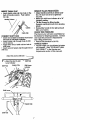
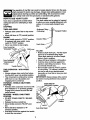
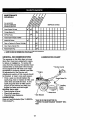
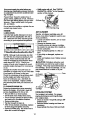
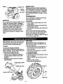
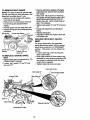
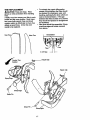
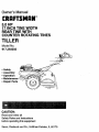
Owner's Manual
£RnFTSMI:IN
5.0 HP
17 INCH TINE WIDTH
REAR TINE WITH
COUNTER ROTATING TINES
TILLER
Model No.
917.293202
•
•
•
•
•
Safety
Assembly
Operation
Maintenance
Repair Parts
©
CAUTION:
Read and follow all
Safety Rules and Instructions
before operatingthis equipment
Sears, Roebuck and Co., Hoffman. Estates, IL 60179
Service and Adjustments...................... 15
Storage ................................................. 19
Troubleshooting.................................... 20
Illustrated Pads List.............................. 42
Parts Ordering ....................... Back Cover
Warranty ................................................
2
Safety Rules ...........................................
2
Product Specifications .......................... 4
Assembly ................................................
5
Operation., ......................................
3 &8
Maintenance .........................................
13
LIMITED ONE YEAR WARRANTY
ON CRAFTSMAN
TILLER
For one (1) year from date of purchase, when this Craftsman Tiller is maintained, lubricated, and tuned up according to the operating and maintenance instructions in the
owner's manual, Sears will repair free of charge any defect in material or workmanship.
This Warranty does not Cover:
• Expendable items which becom e worn during normal use, such as tines, spark plugs,
air cleaners and belts.
• Repairs necessary because of operator abuse or negligence, including bent crankshafts and the failure to maintain the equipment according to the instructions contained in the owrjer's manual.
• If this Craftsman'Tiller is L_sed for commercial or rental purposes, this Warranty
applies for only thirty (30) days fi'om the date of purchase.
Warranty service is available by returning the Craftsman Titler to the nearest Sears service center/department in the United States. This warranty applies only while this product is in use in the United States.
This Warranty gives you specific legal rights, and you may also have other rights which
vary from state to state.
SEARS, ROEBUCKAND
CO., D/817WA, HOFFMAN ESTATES, IL 60179
TRAINING
• Do not operate the equipment without
wearing adequate outer garments. Wear
footwear that will improve footing on
slippery surfaces.
° Handle fuel with cars; it is highly flammable.
• Read the Owner's Manual carefully. Be
thoroughly familiar with the controls and
the proper use of the equipmenL Know
how to stop the unit and disengage the
controls quickly.
• Never allow children to operate the
equipment. Never allow adults to operate the equipment without proper
instruction.
• Use an approved fuel container.
* Never add fuel to a running engine or
hot engine.
° Fill fuel tank outdoors with extreme care.
Never fill fuel tank indoors.
, Replace gasoline cap securely and
clean up spilled fuel before restarting.
- Use extension cords and receptacles as
specified by the manufacturer for all
units witb electric drive motors or electric
• Keep the area of operation clear of all
persons, particularly small children, and
pets.
PREPARATION
• Thoroughly inspect the area where the
equipment is to he used and remove all
foreign objects.
• Disengage all clutches and shift into
neutral before starting the engine (mo-tor).-
starting motors.
• Never attempt to make any adjustments
while the engine (motor) is running
(except where specifically recommended by manufacturer).
2
MAINTENANCE
OPERATION
AND STORAGE
• Do not put hands or feet near or under
• Keep machine _,attachments, and
accessories in safe working condition.
rotatingpads.
•
Check shear pins, engine mounting
• Exercise extreme caution when operatbolts, and other bolts at frequent intering on or crossing gravel ddves, walks,
or roads. Stay alert for hidden hazards
vals for proper tightness to be sure the
equipment is in safe working condition.
or traffic. Do not carry passengers.
• Never store the machine with fuel in the
• After strikinga foreign object, stop the
engine (motor), remove the wire from
fuel tank inside a building where ignition
sources are present, such as hot water
the spark plug, thoroughly inspect the
and space heaters, clothes dryers, and
tiller for any damage, and repair the
the like. Allow the engine to cool before
damage before restarting and operating
the tiller.
storing in any enclosure.
• Exercise caution to avoid slipping or
• Always refer to the operator's guide
instructions for important details if the
falling.
• If the unit should start to vibrate abnortiller is to be stored for an extended period.
mally,stop the engine (motor) and check
immediately for the cause. Vibration is
_,CAUTION:
Always disconnect spark
generally a waming of trouble.
plug wire and place wire where it cannot
• Stop the engine (motor) when leaving
._contact spark plug in order to prevent accithe operating position.
dental starting whe.n setting up, transport• Take all possible precautions when leav- ing, adJustin.g or making repairs.
ingthe machine unattended. Disengage WARNING
the tines, shift into neutral, and stop the
The engine exhuast from this product conengine.
tains chemicals known to the State of
• Before cleaning, repairing, or inspecting, Califomia to cause cancer, berth defectd, or
shut off the engine and make certain all
other reproductive harm.
moving parts have stopped. Disconnect
the spark plug wire, and keep the wire
away from the plug to prevent accidental
starting. Disconnect the cord on electric
motors.
• Do not run the engine indoors; exhaust
fumes are dangerous.
• Never operate the tiller without proper
guards, plates, or other safety protective
devices in place.
• Keep children and pets away.
• Do not overload the machine capacity
by attempting to till too deep at too fast a
rate. _
• Never operate the machine at high
speeds on slippery surfaces. Look
behind and use care when backing.
• Never allow bystanders near the unit.
• Use only attachments and accessories
approved by the manufacturer of the
tiller.
• Never operate the tiller without good visibilityor light.
• Be careful when tilling in hard ground.
The tines may catch in the ground and
propel the tiller forward. If this occurs,
let go of the handlebars and do not
re_trair_the machine.
3
MAINTENANCE
AGREEMENT
A Seers Maintenance Agreement Is available on this product. Contact your nearest
Sears store for details.
CUSTOMER RESPONSIBILITIES
• Read and observe the safety rules.
• Follow a regular schedule in maintaining, caring for and using your tiller.
• Follow the instructionsunder the
=Maintenance" and =Storage" sections of
this Owner's Manual.
PRODUCT SPECIFICATIONS
-IORSEPOWER:
5.0 HP
:)ISPLACEMENT:
12 CU. IN. (206CC)
3ASOLINE CAPACITY:
3 Quarts
Unleaded Regular
_)lL (API-SF/SG/SH)_
SAE 30
(Above 32°1:)
SAE 5W-30
(Below 32°F)
3APACITY: 20 oz.)
3PARK PLUG :
(GAP: .030")
Champion RJ19LM
OR J19LM
WARNING:
This unit is equipped with an
intemal combustion engine and should not
be used on or near any unimproved forestcovered, brush-covered or grass covered
land unless the engine's exhaust system is
equipped with a spark arrester meeting
applicable local or state laws (if any). If a
spark arrester is used, it should be maintained in effective working order by the
operator.
In the state of California the above is
Congratulations
on your purchase of a
Craftsman Tiller. It has been designed, engineered and manufactured togive you the
best possible dependability andpedormance.
Should you experience any problems you
cannot easily remedy, please contact your
nearest authorized Sears Service
Center/Department.
We have competent,
well-trained technicians and the proper
tools to service or repair this unit.
Please read and retain this manual. The
instructions will enable you to assemble
required by law (Section 4442 of the
California Public Resources Code). Other
states may have similar laws. Federal
laws apply on federal lands. See your
Sears Authorized Service Center for spark
arrester. Refer to the Repair Parts section
of this manual for part number.
and maintainyour tillerproperl,y. Always
observe the SAFETY RULES.
Your new tiller has been assembled at the
factory with exception of those parts left
unassembled for shipping purposes. To
ensure safe and proper operation of your
tiller all parts and hardware you assemble
must be tightened securely. Use the correct tools as necessary to insure proper
tightness.
These accessories were available when the tiller was purchased. They are also available at most Sears Retail outlets and Service Centers. Most Sears Stores can order
repair parts for you when you provide the model number of your tiller.
ENGINE
F ®I
"I 1£1
-ITI
TILLER PERFORMANCE
TILLER MAINTENANCE
BEI.T
. 11N_
-
_
4
PIN
HAIRPIN CUP
Your new tiller has been assembled at the factory with exception of thosp parts left
unassembled for shipping purposes. To ensure safe and proper operation of your tiller
all parts and hardware you assemble must be tightened securely. Use the correct tools
as necessary to insure proper tightness.
TOOLS
REQUIRED
FRONT
FOR ASSEMBLY
A socket wrench set will make assembly
easier. Standard wrench sizes are listed.
(1) Utility knife
(1) Wire cutter
(I) Tire pressure gauge
(1) Screwdriver
(1) Pair of pliers
(1) 9/16" wrench
OPERATOR'S POSITION
When right or left hand is mentioned in
this manual, it means when you are in
the operating position (standing behind
tiller handles).
E
LEFT
l
RIGHT
OPERATOR'S
POSITION
CONTENTS OF HARDWARE PACK
©
/lllllll/Y
(2) Handle
Locks
(1) Carriage Bolt
3/8-16 UNCx I Gr. 5
(2) Hairpin
Clips
_
(,)
(1) Center Locknut
3/8-16 UNC
(1) Cable Clip
J
3/1)Pivot Bolt
8-16 UNC Grade 5
,
(_
°1
Extra Shear Pins & Clips
(1) FlatWasher
0
13/32 x 1 x 11Ga.
(1) Handle Lock Lever
UNPACKING CARTON
_CAUTION:
Be careful of exposed staples when handling or disposing of cartoning material.
IMPORTANT:When
unpacking and
assembling tiller, be careful hot to stretch
or kink cables.
• While holding handle assembly, cut
cable ties securing handle assembly to
top frame. Let handle assembly rest on
tiller.
Loosen
Lever to Move
f
• Remove top frame of carton.
• Slowly ease handle assembly up and
place on top of carton.
• Cut down fight hand front and fight hand
rear comers of carton, lay side carton
wall down.
• Insert pivot bolt in front part of plate and
tighten.
• Cut down remaining comers of carton
and lay panels flat.
• Lower the handle assembly. Tighten nut
on carriage bolt so handle moves with
some resistance. This will allow for eas"ier adjustment.
• Place flat washer on threaded end of
handle lock lever.
• Remove packing material from handle
assembly.
• Separate shiftrod from handle assembly.
• Insert handle lock lever through handle
base and gearcase. Screw in handle
lock lever just enough to hold lever in
place.
• Insert second handle lock (with teeth
inward) in the slot of the handle base
(just inside of washer).
• Raise handle assembly to highest position and securely tighten handle lock
lever by rotating clockwise. Leaving
handle assembly in highest position will
make it easier to connect shift rod.
le
mbly
INSTALL HANDLE
• Insert one handle lock (with teeth facing
outward) in gearcase notch. (Apply
grease on smooth side of handle lock to
aid in keeping lock in place until handle
assembly is lowered into position.)
Viewed from r.h. side of tiller
Handle Lock
Gearcase
Slot
Gearcase Notch
Handle Lock
(-
Handle Base
• Grasp handle assembly. Hold in "up"
position. Be sure handle lock remains in
gearcase notch. Slide handle assembly
into position.
• Rotate handle assembly down. Insert
rear c,ardage bolt first, with head of bolt
on L.H. side of tiller and loosely assemble Iocknut.
6
Flat Washer
Lock
INSERT CABLE
REMOVE TILLER FROM CRATE
• Adjust handle assemby to lowest posi:
tion. Be sure lock lever is tightened
securely.
• Make sure shift lever indicator is in =N"
(neutral) position.
• Tilt tiller forward by liftinghandle.
Separate cardboard cover from leveling
shield.
• Rotate tiller handle tOthe right and pull
tiller out of carton.
CHECK TIRE PRESSURE
The tires on your unit were overinflated at
the factory for shipping purposes. Correct
and equal tire pressure is important for
best tilling performance.
• Reduce tire pressure to 20 PSI.
HANDLE HEIGHT
• Handle height may be adjusted to better
suit operator. (See "TO ADJUST HANDLE HEIGHT" in the Service and
Adjustments section Ofthis manual).
CLIP
r
• Insert plastic cable clip into hole on the
back of handle column. Push cables
into clip.
Handle Column
\
Cables
Cable Clip
CONNECT SHIFT ROD
• Insert end of shift rod farthest from bend
into hole of shift lever indicator.
• Insert hairpin clip through hole of shift
rod to secure.
• Insert other end of shift rod into hole in
shift lever.
• Insert second hairpin clip through hole of
shift rod.
Attach this end to shift lever
[_Attach
this End To shift
Lever Indicator
Shift Rod
Shift Lever _.
Hairpin Clip
Shift Rod
Shift Lever
Indicator
n
7
. .
These symbols may appear on your Tiller or in literature supplied with the product.
Leam and understand their meaning.
FORWJ_qO
NEUTRAL
REVEPJE
_UIION
OR WNqNING
_
0_1
FU_
OIL
OFF
KNOW YOUR TILLER
READ THIS OWNER'S
TILLER.
MANUALAND
SAFETY
RULES BEFORE
OPERATING
YOUR
Compare the illustrations with your tiller to familiarize yourself with the location of various controls and adjustments. Save this manual for future reference.
Drive Control Bar
Control
Shift Lever
Choke Control
Leveling
Recoil
Starter
• Handle
_
MEETS ANSI SAFETY
REQUIREMENTS
Our tillers conform to the safety standards of the American National Standards Institute.
DRIVE CONTROL
tines.
DEPTH STAKE
tillel"will dig.
LEVELING
SHIFT LEVER - Used to shift transmission
BAR - Used to engage
- Controls
SHIELD
gears.
SHIFT LEVER INDICATOR - Shows which
gear the transmission is in.
RECOIL STARTER HANDLE - Used to
start the engine.
CHOKE CONTROL - Used when starting
depth at which
- Levels tilled soil.
OUTER SIDE SHIELD - Adjustable to protect small plants from being buried..
THRO!'rLE
CONTROL
- Used to control
_acold engine.
- engine speed.
8
The operation of any tiller can result in foreign objects thrown into the eyes,
which canrasult in severe eye damage. Always wear safety glasses or eye
shields before starting your tiller and while tilling. We recommend a wide
vision safety mask over the spectacles or standard safety glasses.
HOW TO USE YOUR TILLER
DEPTH STAKE
Know how to operate all controls before
adding fuel and oil or attempting to start
engine.
STOPPING
The depth stake can be raised or lowered
to allow you more versatile tilling and cultivating, or to more easily transport your
tiller.
TINES AND DRIVE
Shallowest "Riling
(Cultivating)
• Release drive control bar to stop movement.
• Move shift lever to "N" (neutral) position.
ENGINE
• Move throttle control to "STOP" position.
If equipped with stop switch, move
switch to =STOP" position.
• Never use choke to stop engine.
Drive Control Bar
"ENGAGED" Position
Shift Lever
Deeptest Tilling
"_Transport Poc,ition
J
Depth Stake
TILLING
• Release depth stake pin. Pull the depth
stake up for increased tilling depth.
Place depth stake pin in hole of depth
stake to lock in position.
• Place shift lever indicator in till position.
• Hold the drive control bar against the
handle to start tilling movement. Tines
and wheels will both turn.
"DISENGAGED"
Position
Throttle Control
TINE OPERATION
DRIVE
• Move throttle control to =FAST" position
for deep tilling. To cultivate, throttle control can be set at any desired speed,
depending on how fast or slow you wish
to cultivate.
- WITH WHEEL
• Always release drive control bar before
moving shift lever into another position.
• "line movement is achieved by moving
shift lever to ( _ ) till position and
engaging drive control bar.
FORWARD - WHEELS ONLY/TINES
STOPPED
• Release drive control bar and move shift
IMPORTANT: Always release drive control
bar before moving shift lever into another
position.
Depth Stake Pin
Position
lever indicator to =F" (forward) position.
Engage drive control bar and tiller will
move forward.
REVERSE - WHEELS ONLY/TINES
STOPPED
• DO NOT STAND DIRECTLY BEHIND
TILLER.
• Release the ddve control bar.
• Move throttle control to =SLOW" position.
• Move sl_ift lever indicator to "R"
Nut "B"
Outer Side Shield
(reverse) position.
• Hold drive control bar against the handle
to start tiller movement.
9
"Locked"
Position
TURNING
CHECK ENGINE OiL LEVEL
• Release the drive control bar;
• The engine in your unit has been
• Move throttle control to "SLOW" posishipped, from the factory, already filled
tion.
with SAE 30 summer weight oil:
• Place shift lever indicator in =F" (forward) • With engine level, clean area around oil
position. ]]nes will not tum.
filler plug and remove plug.
• Lift handle to raise tines out of ground.
• Engine oil should be to point of overflow• Swing the handle in the opposite direcing when engine is level. For approxition you wish to tum, being careful to
mate capacity see =PRODUCT SPECIkeep feet and legs away from tines.
FICATIONS" on page 4 of this manual.
All oil must meet A.RI. Service
• When you have completed your tumaround, release the drive control bar and
Classification SF, SG or SH.
lower handle. Place shift lever in till
• For cold weather operation you should
position and move throttle control to dechange oil for easier starting (See oil
sired speed. To begin tilling, hold drive
viscosity chart in the Maintenance seccontrol bar against the handle.
tion of this manual).
OUTER SIDE SHIELDS
• To change engine oil, see the
Maintenance section in this manual.
The back edges of the outer side shields
are slotted so that the shields can be
raised for deep tilling and lowered for shallow tilling to protect small plants from
Oil
being buried. Loosen nut "A" in slot and
FiUer
Oil Level
nut "B'. Move shield to desired position
Plug
(both sides). Retighten nuts.
TO TRANSPORT
,_CAUTION: Before liftingor transporting, allow tiller engine and muffler to cool.
Disconnect spark plug wire. Drain gaso3il Drain Plug
line from fuel tank.
AROUND THE YARD
ADD GASOLINE
• Release the depth stake pin. Move the
• Fill fuel tank. Use fresh, clean, regular
depth stake down to the top hole for
unleaded gasoline. (Use of leaded
transporting the tiller. Place depth stake
gasoline will increase carbon and lead
pin in hole of depth stake to lock in posioxide deposits and reduce valve life.
tion. This prevents tines from scuffing
IMPORTANT: When operating in temperathe ground.
tures below 32°F (0°C), use fresh, clean,
• Place shiftlever indicator in =F" (forward) winter grade gasoline to help insure good
position for transporting.
cold weather starting.
• Hold the drive control bar against the
WARNING: Experience indicates that alcohandle to start tiller movement. Tines
hol blended fuels (called gasohol or using
will not tum.
ethanol or methanol) can attract moisture
• Move throttle control to desired speed.
which leads to separation and formation of
AROUND TOWN
acids dudng storage. Acidic gas can dam• Disconnect spark plug wire.
age the fuel system of an engine while in
• Drain fuel tank.
storage: To avoid engine problems, the
• Transport in updght position to prevent
fuel system should be emptied before
oil leakage.
storage of 30 days or longer. Drain the
gas tank, start the engine and let it run
BEFORE STARTING ENGINE
until the fuel lines and carburetor are
IMPORTANT: Be very careful not to allow
empty. Use fresh fuel next season. See
dirt to enter the engine when checking or
Storage section of this manual for additionadding oil or fuel. Use clean oil and fuel
al information: Never use engine'or carbuand store in approved, clean, covered conretor cleaner products in the fuel tank or
tainers, use clean fill funnels.
permanent damage may occur.
lO
,_CAUTtON:
Fill to within 1/2 inch of top
of fuel tank to prevent spills and to allow
for fuel expansion. If gasoline is accidentally spilled, move machine away from
area of spill. Avoid creating any source of
ignitionuntil gasoline vapors have disappeared.
Do not overfill. Wipe off any spilled oil or
fuel. Do not store, spill or use gasoline
near an open flame.
TO START ENGINE
,_,CAUTION:
Keep tine control in "OFF"
position when starting engine.
When starting engine for the first time or if
engine has run out of fuel, it will take extra
pulls of the recoil starter to move fuel from
the tank to the engine.
• Make sure spark plug wire is properly
connected.
• Plac_ throttle control in "FAST" position.
• Move choke control to full "CHOKE"
position. Grasp recoil starter handle with
one hand and grasp tiller handle with
other hand. Pull rope out slowly until
engine reaches start of compression
cycle (rope will pull slightly harder at this
point).
• Pull recoil starter handle quickly. Do not
let starter handle snap back against
starter. Repeat if necessary.
• If engine fires but does not start, move
choke control to half choke position. Pull
recoil starter handle until engine starts.
• When engine starts, slowly move choke
control to =RUN" position as engine
warms up.
Spark Plug
Choke
Control
Recoil
Starter
Handle
NOTE: If at a high altitude (3000 feet) or
in cold temperatures (below 32°F), the carburetor fuel mixture may need to be
adjusted for best engine performance.
See "TO ADJUST CARBURETOR" in the
Service and Adjustments section of this
manual.
NOTE: If engine does not start, see troubleshooting points.
TILUNG HINTS
,_CAUTION: Until you are accustomed to
handling your tiller, start actual field use
with throttle in slow position (mid-way
between =FAST" and "IDLE').
• Tilling is digging into, fuming over, and
breaking up packed soil before planting.
Loose, unpacked soil helps root growth.
Best tilling depth is 4= to 6". A tiller will
also clear the soil of unwanted vegetation. The decomposition of this vegetable matter endches the soil.
Depending on the climate (rainfall and
wind), it may be advisable to till the soil
at the end of the growing season to further conditionthe soil.
• Soil conditions are important for proper
tilling. Tines will not readily penetrate
dry, hard soil which may contribute to
excessive bounce and difficulthandling
of your tiller. Hard soil should be moistened before tilling;however, extremely
wet soil will "ball-up" or clump during tilling. Wait untilthe soil is less wet in order
to achieve the best results. When tilling
in the fall, remove vines and long grass
to prevent them from wrapping around
the tine shaft and slowing your tilling
operation.
• You will find tilling much easier if you
leave a row untilled between passes.
Then go back between tilled rows. There
are two reasons for doing this. First,
wide tums are much easier to negotiate
than about-faces. Second, the tiller
won't be pulling itself, and you, toward
the row next to it.
NOTE: Awarm engine requires less choking to start.
• Move throttle control to desired running
position.
• Allow engine to warm up for a few minutes before engaging tines.
11
ADJUST
ING
• Do not lean' oh hand_. This takes
weight off the wheels and reduces traction. To get through a really tough section of sod or hard ground, apply upward
pressure on handle or lower the depth
stake.
TINE SHEAR
WHEELS
FOR
CULTIVAT-
• Place blocks under dght hand side of
tiller and remove hairpin clip and clevis
pin from right hand wheel.
• Move wheel outward approximately 1
inch (2.5 cm) until hole in inner wheel
hub lines up with inner hole in axle.
• Replace clevis pin and hairpin clip on
inside of wheel and remove blocks.
PINS
The tine assemblies on your tiller are
secured to the tine shaft with shear pins
(See "FINE REPLACEMENT" in the
Service and Adjustments section of this
manual).
If the tiller is unusually overloaded or
jammed, the shear pins are designed to
break before internal damage occurs to
the transmission.
• If shear pin(s) break, replace only with
those shown in the Repair Parts section
of this manual.
• Repeat preceding steps on left hand
side.
OUTER VIEW OF TIRE
Clevis Pin
i
Haiq_pin clip
INNER VIEW OF TIRE
F'_
.t",,
(_
1
CULTIVATING
Cultivating is destroying the weeds
between rows to prevent them from robbing nourishment and moisture from the
plants. At the same time, breaking up the
upper layer of soil crust will help retain
moisture i-nthe soil. Best digging depth is
1" to 3" (2.5-7.5 cm). Lower the outer side
shields to protect small plants from being
buried.
• Cultivate up and down the rows at a
speed which will allow tines to uproot
weeds and leave the ground in rough
condition, promoting no further growth of
weeds and grass
NOTE: In extremely rough conditions and
while cultivating, the wheels should be
moved outward on the axle for increased
stability.
12
SCHEDULE
M.,..E.NCO
AS YOU COMPLETE
/_.(_f._'_
Check EngineO, Level
llt
SERVICE
DATES
I_
Change Engine Oil
_
0il Pivot Points
IV/ I
Inspect Spark Arrester / Muffler
Inspect Air Screen
i
Clean or Replace Air Cleaner Cartridge
I/2
Clean Engine Cylinder Fins
V'
Replace; Spark Plug
I/
1. ChangemoreoltenwhenopecalJng
undera heart loador in_ ambienttemperature_
2 - Semitemoreoftenwhenopera,rigindirtyordustycondl6ons.
GENERAL
RECOMMENDATIONS
LUBRICATION
The warranty on this tiller does not cover
items that have been subjected to operator abuse or negligence. To receive full
value from the warranty, the operator must
maintain tiller as instructed in this manual.
CHART
* Throttle Control
Some adjustments will need to be made
periodically to properly maintain your tiller.
All adjustments in the Service and
Adjustments section of this manual should
be checked at least once each season.
• Once a year you should replace the
spark plug, clean or replace air filter, and
check tines and belts for wear. A new
spark plug and clean air filter assure
proper air-fuel mixture and help your
engine run better and last longer.
BEFORE EACH USE
• Check engine oil level.
• Check tine operation.
• Check for loose fasteners.
Leveling
Shield
Hinges
Wheel Hub
* Idler Bracket
LUBRICATION
Keep unit well lubricated (See =LUBRICATION CHART').
* SAE 30 OR 5W-30 MOTOR OIL
** REFER TO MAINTENANCE "ENGINE" SECTION
13 ¸
Disconnect spark plug wire before performing any maintenance (except carburetor adjustment) to prevent accidental start.ing of engine.
• Refill engine with oil. See =CHECK
ENGINE OIL LEVEL" in the Operation
section of this manual.
Prevent fires! Keep the engine free of
grass, leaves, spilled oil, or fuel. Remove
fuel from tank before tipping unit for maintenance. Clean muffler area of all grass,
dirt, and debds.
Oil Level
Do not touch hot muffler or cylinder fins as
contact may cause bums.
Oil Filler Plug
ENGINE
AIR CLEANER
LUBRICATION
Service air cleaner cartridge every 50
hours, more often if engine is used in very
dusty conditions.
• Loosen air cleaner screws, one on each
side of cover.
• Remove air cleaner cover.
Use only high quality detergent oil rated
with API service classification SF, SG or
SH. Select the oil's SAE viscosity grade
according to your expected temperature.
• Carefully remove air cleaner cartridge.
Be careful. Do not allow dirt or debds to
fall into carburetor.
• Clean by tapping gently on a flat surface.
• If very dirty or damaged, replace cartridge.
• Clean and replace cover. Tighten screws
NOTE: Although muifi-viscosity oils (5W30, 10W-30, etc.) improve starting in cold
weather, these multi-viscosity oils will
result in increased oil consumption when
used above 32°F (0°C). Check your
engine oil level more frequently to avoid
possible engine damage from running low
on oil.
securely.
_I_CAUTION:
Petroleum solvents, such
as kerosene, are not to be used to clean
cartridge. They may cause deterioration of
the cartridge. Do not oil cartridge. Do not
use pressurized air to clean or dry cartddge.
Cover
Air Cleaner
Change the oil after every 50 hours of
operation or at least once a year if the tiller
is not used for 50 hours in one year.
Check the crankcase oil level before starting the engine and after each five (5)
hours of continuous use. Add SAE 30
motor oil or equivalent. Tighten oil filler
plug securely each time you check the oil
level.
TO CHANGE
ENGINE
Screw_
OIL
Air Cleaner ",_.._y/_)
Cartridge
Determine temperature range expected
before oil change. All oil must meet API
service classification SF, SG or SH.
• Be sure tiller is on level surface.
• Oil will drain more freely when warm.
• Use a funnel to prevent oil spill on tiller,
and catch oil in a suitable container.
COOLING
_J' J
SYSTEM
Your engine is air cooled. For proper
engine performance and long life keep
your engine clean.
* Clean air screen frequently using a stiffbristled brush.
• Remove drain plug.
• Tip tiller forward to drain oil.
• After oil has drained completely, replace
oil drain plug and tighten securely.
• Remove oil filler plug. Be careful not to
allow dirt to enter the engine.
* Remove blower housing and clean as
necessary.
• Keep cylinder fins free of dirt and chaff.
14
Muffler
r Fins
Housing
SPARK PLUG
....
Replace spark plugs at the beginning of
each tilling season or after every 50 hours
of use, whichever comes first. Spark plug
type and gap setting is shown in "PRODUCT SPECIFICATIONS" on page 4 of this
manual.
TRANSMISSION
Your transmission is sealed and will only
require lubricationif serviced.
MUFFLER
CLEANING
Do not operate tiller without muffler. Do not
tamper with exhaust system. Damaged
mufflers or spark arresters could create a
fire hazard. Inspect periodically and replace if necessary. If your engine is
equipped with a spark arrester screen
assembly, remove every 50 hours for
cleaning and inspection. Replace if damaged.
• Clean engine, wheels, finish, etc. of all
foreign matter.
• Keep finished surfaces and wheels free
of all gasoline, oil, etc.
• Protect painted surfaces with automotive
type wax.
We do not recommend using a garden
hose to clean your unit unless the muffler,
air filter and carburetor are covered to
keep water out. Water in engine can result
in a shortened engine life.
_,CAUTION:
TIRE CARE
Disconnect spark plug wire
ACAUTION:
When mounting tires, unless beads are seated, overinflation can
cause an explosion.
• Maintain 20 pounds of tire pressure. If
tire pressures are not equal, tiller will
pull to one side.
• Keep tires free of gasoline or oil which
can damage rubber.
TO REMOVE WHEEL
• Place blocks under transmission to keep
tiller from tipping.
• Remove hairpin clip and clevis pin from
wheel.
• Remove wheel and tire.
from spark plug and place wire where it
cannot come into contact with plug.
TILLER
TO ADJUST HANDLE HEIGHT
Select handle height best suited for your
tilling conditions. Handle height will be different when tiller digs into soil.
• First loosen handle lock lever.
• Handle can be positioned at different
settings between =HIGH" and "LOW"
positions.
• Retighten handle lock lever securely
after:adjusting.
• Repair tire and reassemble.
Handle (High) Position
Handle Lock Lever
Handle (Low) Position
Hairpin Clip
15
TO REMOVE BELT GUARD
NOTE: For ease of removal, =remove hairpin clip and clevis pin from left wheel. Pull
wheel out from tiller about I inch.
• Remove two (2) screws and washers
from side of belt guard.
• Remove hex nut and washer from bottom of belt guard (located behind
wheel).
• Pull belt guard out and away from unit.
• Replace belt guard by reversing above
procedure.
Belt Guard
Screw and Washer/_
/
_
Rex Nut
__/J//
and
/
Washer
_---__../
_,_ (L.o_.ted
V_._'_F_I___-_._:
_p_ Behind
• Remove old belt by slipping off engine
pulley first then remove from transmission pulley.
• Place new belt in groove of transmission pulley and into engine pulley. BELT
MUST BE IN GROOVE ON TOP OF
IDLER PULLEY. NOTE POSITION OF
BELT TO GUIDES.
• "tqghten belt guides "A" and "B" and stud
=C".
• Check belt adjustment
below.
as descdbed
• Replace belt guard.
• Reposition wheel and replace
and hairpin clip.
GROUND
MENT
DRIVE
BELT
clevis pin
ADJUST-
For proper belt tension, the extension
spring should have about 5/8 inch stretch
when drive control bar is in =ENGAGED"
Screw and'_
Washer
_
I
Hairpin Clip and
Clevis Pin
TO REPLACE GROUND DRIVE
BELT
• Remove belt guard as described in "TO
REMOVE BELT GUARD".
• Loosen belt guides "A" and =B"and
also stud "C".
position. This tension can be attained as
follows:
• Loosen cable clip screw secudng the
drive control cable.
• Slide cable forward for less tension and
rearward for more tension until about 5/8
inch stretch is obtained while the ddve
control bar is engaged.
• '_ghten cable clip screw securely.
Cable
Belt Guide "A"
Engin ; Pulley
Stud =C"
Idler Pulley
Exten_on Spdng"
Transmission Pulley
16
_Screw
Ddve Control Cable
TINE REPLACEMENT
_,CAUTION:
Tines are sharp. Wear
gloves or other protection when handling
tines.
A badly worn tine causes your tiller to work
harder and dig more shallow. Most important, wom tines cannot chop and shred
organic matter as effectively nor bury it as
deeply as good tines. Atine this worn
needs to be replaced.
• To maintain the spperb tilling performance of this n_achine the tines should
be checked for sharpness, wear, and
bending, particulady the tines which are
next to the transmission. If the gap
between the tines exceeds 3-1/2 inches
they should be replaced or straightaned
as necessary.
• New tines should be assembled. Sharpened tine edges will rotate rearward
from above.
New "line
om "line
I
I
I
3-1/2" Max
I
l
I
---!
Clip
_oUtanter"rine
tton
Hairpin Clip
Sharp Edge
\
Sharp Edge
Shear Pin
Shear Pin _"
Sharp Egde
17
ENGINE
Maintenance,repair,oPrep_laeement
of the
emissioncontroldevicesandsystems,
whicharebeingdoneatthe customers
IDLE RPM ADJUSTMENT
• Rotate throttle linkage counterclockwise
and hold against stop while adjusting
idle speed adjusting screw to obtain
1750 RPM. Release throttle linkage.
High speed stop is factory adjusted. Do
not adjust or damage may result.
IMPORTANT: Never tamper with the engine governor, which is factory set for
proper engine speed, overspeeding the
engine above the factory high speed setting can be dangerous. If you think the
engine-governed high speed needs adjusting, contact your nearest sears service
centerdepartment, which has proper
equipment and experience to make any
necessary adjustments.
expense, may be performed by any nonroad engine repair establishment or"individual. Warranty repairs must be performed by an authorized engine manufacturer's service outlet.
TO ADJUST THROTTLE
CONTROL
CABLE
• Loosen cable clamp screw to allow
cable to move.
• Move throttle control lever on upper handle to "FAST" position.
• Pull throttle cable out until engine bellcrank is back as far as it will go.
• Hold cable in this position and tighten
clamp screw securely.
Throttle Linkage
Throttle Cable
Idle Speed AdjustingScrew
Bell Crank
TO ADJUST
CARBURETOR
The carburetor has a high speed jet and
has been preset at the factory and adjustment should not be necessary. However,
minor adjustments may be required to
compensate for differences in fuel, temperature, altitude or load. If the carburetor
does need adjustment, proceed as follows.
FINAL SETTING
• Start engine and allow to warm for five
minutes.
• With throttle control lever in =SLOW"
position.
18
Throttle Stop
Immediatelyprepareyourtiller for
NOTE: Fuel stabilizer is an acceptable
altemative in minimizingthe formation of
fuel gum deposits during storage. Add stabilizer to gasoline in fuel tank or storage
container. Always follow the mix ratio
found on stabilizer container. Run engine
at least 10 minutes after adding stabilizer
to allow the stabilizer to reach the carburetor. Do not drain the gas tank and carburetor if using fuel stabilizer.
storage
at the end of the season or if the unit will
not be used for 30 days or more.
_,CAUTiON:
Never store the tiller with
gasoline in the tank inside a building
where fumes may reach an open flame or
spark. Allow the engine to cool before
storing in any enclosure.
TILLER
ENGINE
• Clean entire tiller (See =CLEANING" in
the Maintenance section of this manual).
• Inspect and replace belts, if necessary
(See belt replacement instructions in the
Service and Adjustments section of this
manual).
• Lubricate as shown in the Maintenance
section of this manual.
OIL
Drain oil (with engine warm) and replace
with clean oil (See =ENGINE" in the
Maintenance section of this manual).
CYLINDER
• Remove spark plug.
• Pour 1 ounce (29 ml) of oil through
spark plug hole into cylinder.
• Pull starter handle slowly several times
to distribute oil
• Be sure that all nuts, bolts and screws
are securely fastened.
Inspect moving
parts for damage, breakage and wear.
Replace if necessary.
• Touch up aU rusted or chipped paint surfaces; sand lightly before painting.
• Replace with new spark plug.
OTHER
• Do not store gasoline from one season
to another.
ENGINE
• Replace your gasoline can if your can
starts to rust. Rust and/or dirt in your
gasoline will cause problems.
• If possible, store your unit indoors and
cover it to give protection from dust and
dirt.
FUEL SYSTEM
IMPORTANT:
It is important to prevent
gum deposits from forming in essential fuel
system parts such as the carburetor, fuel
filter, fuel hose, or tank during storage.
also, experience indicates that alcohol
blended fuels (called gasohol or using
ethanol or methanol) can attract moisture
which leads to separation and formation of
acids during storage. Acidic gas can damage the fuel system of an engine while in
storage.
• Drain the fuel tank.
• Cover your unit with a suitable protective
cover that does not retain moisture. Do
not use plastic. Plastic cannot breathe
which allows condensation to form and
will cause your unit to rust.
IMPORTANT:
Never cover tiller while
engine and exhaust areas are still warm.
• Start the engine and let it run until the
fuel lines and carburetor are empty.
• Never use engine or carburetor cleaner
products in the fuel tank or permanent
damage may occur.
• Use fresh fuel next season.
19
PROBLEM
CORRECTION
CAUSE
I
Will not start
1. Out of fuel.
2. Engine not "CHOKED"
propedy.
3. Engine flooded.
4, Dirty air cleaner,
5. Water in fuel.
6. Clogged fuel tank.
7. Loose spark plug wire.
8. Bad spark plug or
improper gap.
9. Carburetor out of adjustment.
Hard to start
1. Throttle control not set
properly.
2. Dirty air cleaner.
1. Fill fuel tank.
2. See =TO START ENGINE" in.the
Operation section.
3. Wait several minutes before
attempting to start.
4. Clean or replace air cleaner car
tridge.
5. Drain fuel tank and carburetor,
and refill tank with fresh gasoline.
6. Remove fuel tank and dean.
7. Make sure spark plug wire is seat
ed propedy on plug.
8. Replace spark plug or adjust gap.
9. Make necessary adjustments.
1,
Place throttle control in =FAST"
position.
2. Clean or replace air cleaner car
tddge,
3. Replace spark plug or adjust gap.
3. Bad Spark plug or
improper gap.
4. Stale or dirtyfuel,
4. Drain fuel tank and refill with fresh
5. Loose spark plug wire.
6. Carburetor out of.
gasoline.
5. Make sure spark plug wire is seat
ed propedy on plug.
6. Make necessary adjustments.
adjustment.
Loss of power
1. Engine is ovedoeded.
2. Dirty air cleaner.
1. Set depth stake and wheels for
shallower tilling.
2. Clean or replace air cleaner car
3. Low oil level/dirty oil.
4. Faulty spark plug.
3. Check oHleval/chamje oil.
4. Clean and regap or charge spark
5. Oil in fuel.
5. Drain and oiean fual tan1<and
6. Stale or dirty fuel.
re_l, and_ean carburetor.
6. Drain fuel tank and refitlwith fresh
tridge.
plug.
7. Water in fuel.
8. Clogged fuel tank.
9. Spark plug wire loose.
wire.
10. Dirty engine air screen.
11. Dirty/clogged muffler.
12. Carburetor out of
adjustment.
13. Poor compression.
20
gasoline.
7. Drain fuel tank and carburetor,
and refill tank with fresh gasoline.
8. Remove fuel tank and clean.
9. Connect and tighten spark plug
10. Clean engine air screan.
11, Clean/relplaca muffler.
12. Make necessary edjustments.
13. Contact an authorized Sears
Service Center/Deportment.
PROBLEM
Engineoverheats
CORRECTION
CAUSE
I. L.O_V
oil level/dirtyoil.
2. Dirty engine air screen.
3. Dirtyengine.
4. Partially plugged muffler.
5. Improper carburetor
adjustment.
Excessivebounce/
difficulthandling
1. Ground too dry and hard.
2. Wheels and depth stake
Incorrectly adjusted.
1. Check oil level/change oil.
2. Clean engine air screen,
3. Clean cylinder fins, air screen, muf
fier area.
4. Remove end clean muffler,
5. Adjust carburetor to richer posi
tion.
1. Moisten ground or wait for more
favorable soil conditions.
2. Adjust wheels and depth stake.
Wait for more favorable soil condi
tions.
Soil balls up or
clumps
1. Ground too wet.
1.
Engine runs but
tiller won't move
1. Tins controlis not engaged.
2. V-belt not correctly adjusted.
3. V-belt is off pulley(s).
1, Engage tins control,
2. Inspect/adjust V-belt.
3, Inspect V-belt.
Engine runs but
labors when tilling
1. Tilling too deep.
1. Set depth stake for shallower till
ing.
2. Check throttle controlsetting.
2. Throttle control not propedy
adjusted.
3. Carburetor out of adjustment.
21
3. Make necessary adjustments.
TILLER - - MODEL NUMBER 917.293202
HANDLES
3
2
1
\
11
\
30
KEY
PART
NO.
NO.
1
2
3
4
5
6"
7
8
9
10
11
12
13
14
15
DESCRIPTION
127012X
ControlThrottle
141406
Grip, Handle
110673X
Grommet, Handle
127254X
Bar, Drive ControlAasernbly
6712J
Cap, Vinyl
137119X031 Panel, Control
110641X
Bushing,Split
71191008
* Screw, Phd. #10-24 UNC
GD 2 Phosp
72010520
* Bolt 5/16-18 x 2.50
110646X
Har_le, Grip
STD624(X)3 * Clip, Hairpin
81328
BolL Shoulder
110741X
Handle, Shift
109313X
Gmmrnet, Rubber
110702X
Rod, Shift
KEY
PART
NO.
NO.
16
17
18
19
20
21
22
23
\
\
DESCRIPTION
STD533710 * Bolt, Carriage 3/8-16 x I Gr. 5
109229X
Lock, Handle
STD541437 * Nut, Canterlock 3/8-16
19131611
Washer 13/32 x I x 11 Ga.
109228X
Lever, Lock, Handle
150258
Handle, Aasemble
165197
Clip, Nyl BIkCable
86777
Screw, Hex, Washer Hd, Slotted
#10-24 x 1/2
24
9484R
Clip
25
73970500
Locknut,Hex, Flange
26
110675X
Clutch,Cable
27
STD541025 * Nut, Hax 1/4-20
28
STD551125 * Washer, Lock 1/4
29
STD541462 * Nut, Keps #10-24
31
150696
BOILPivot
• STANDARD HARDWARE - - PURCHASE LOCALLY
NOTE: All componentdimensionsgiven in U.S. Inches.
1 inch= 25.4 mm
42
TILLER
MAINFRAME,
- - MODEL
NUMBER
917.293202
LEFT SIDE
4
20
3O
211
40
24
KEY
PART
NO.
NO.
1
2
3
4
5
6
7
8
9
STD541431
STD551137
STD541037
165710
154734
110111X
STD532505
8700J
86777
10
11
12
13
14
15
16
17
19
20
21
22
9484RSTD551125
STD541(_5
23230506
110652X
STD551031
145102
STD541031
12000028
166504
156117
74770508
KEY
NO.
DESCRIPTION
° Nut, Keps, Flange 5/16-18
*Washer, Lock 3/8
* Nut, Hex 3/8-16
Shield, InnerBelt Guard Rt
Screw Shift Lever
Lever, Shift
* Bolt, Carriage 1/4-20 x 1/2 Gr. 5
Plate, ShiftIndicator
Screw, Hex, Washer Head, Slotted
#10-24 x 1/2
Clip
*Washer, Lock 1/4
* Nut, Hex 114-20
*Screw, Set, 5/16-18x3/8
Spacer, Split 0.327 x 0.42 x 2.09
°Washer 11/32x11/16x16Ga.
Sheave, Transmission
° Nut, Hex 5/16-18
Ring, Retaining
Nut, J Clip #8
Spacer, Spilt 0.327x0.42x1.220
Bolt, Fln Hex 5/16-24 UNF x 1/2
23
PART
NO.
DESCRIPTION
102190X
"nre
150750
Rim
795R
Tire Valve
126875X
Rivet, Ddlled
STD624003 * Clip, Hairpin
165501X558
Guard, Belt
132801
Belt, V
lO4679X
Pulley,Idler
12000032
Ring, Klip
159229
Bracket, idler
I02384X
Bolt,Hax 5/16-16 x 12
I02141X
Shaft, IdlerArm
STD523710 " Bolt,Hex 3/8-16 x I
I02383X
Counten_ghL LH.
74760524
Bolt,Hex 5/16-18x 1-1/2
102331X
Bracket, Reinforcement,LH.
130812
Sheave, Engine
74760544
Bolt, Fin Hex 5/16-18 UNC x 2-3/4
140062
cap
165503
Screw Hex WSh Head #6-18 xl/2
Nut Lock #10-24
6918O
24
25
26
27
28
29
30
31
32
33
34
35
36
37
38
39
40
43
*STANDARD HARDWARE - - PURCHASE lOCALLY
NO'I1E:All componentdimensionsgiven in U.S. inches.
linch = 25A mm
43
TILLER
- - MODEL
NUMBER
917.293202
MAINFRAME, RIGHT SIDE
10
7
KEY
PART
NO.
NO.
1
2
3
4
5
6
7
8
STD541431
102332X
74760524
1_2173X
STD551137
STD541037
STD624003
126875X
DESCRIPTION
* Nut, Keps 5/16-18
Bracket, Reintorcment
Bolt, Hex 5/16-18x1-1/2
CounterWeight, R.H.
* Washer, Lock 3/8
* Nut, He}( 3/8-16
* Clip, Hairpin
Rivet, Drilled
KEY
PART
NO.
NO.
9
10
102190X
150750
795R
.....
DESCRIPTION
1]ra
Rim
TireV'_ve
Engine,(See Breakdown)
Briggs& StrattonModelNo.
137202,TypeNo,1125-E1
* STANDARD HARDWARE - - PURCHASE LOCALLY
NOTE: Aftcomponentdimensionsgiven in U.S.inches.
1 inch = 25.4 mm
44
TILLER
- - MODEL
NUMBER
917.293202
TRANSMISSION
53
44
KEY
PART
NO.
NO.
1
165728
2
165729
3
4
5
6
7
8
9
10
11
12
13
14
15
16
18
19
20
161963
5O20J
1370H
137335
145101
4895H
154467
7392M 10037fK
106160X
142145
8353J
12000039
154466
4358J
12000040
102114X
21
22
23
24
25
27
28
102115X
6803J
102111X
STD551143
STD541143
143009 _
106390X
KEY
DESCRIPTION
NO.
TransmissionAssembly(Includes
Key Nea. 2-54)
Gearcase, L.H. w/Bearing
(Includes Key No. 4)
Gasket, Gearcase
Bearing, Needle
Washer, Thrust 5/8 x 1.10 x 1/32
Pinion, Input
Shaft, Input
Beadng, Needle
Washer, Seal
Ball, Steel
Spring, Shift, Fork
O-Ring
Arm, Shift
Fork, Shift
Ring, Klip
Shaft,Shift
Washer
Ring, Klip
Gear, Assembly,Reverse Idler
(IncludesKey Nce. 21 and22)
Gear, Reverse Idler
Beadng,Needle
Shaft,Reverse Idler
*Washer, Lock 7/16
*Nut, Hex 7116-20
Bearing, Shaft, Ground Drive
Spacer 0.765xl.125x1.23
PART
NO.
29
30
31
32
33
34
35
36
102134X
150737
143008
106388X
102121X
102112X
102101X
154355
37
38
39
40
41
42
43
44
48
4422J
154356
105345X
105346X
8358J
4220R
106146X
155236
165732
49
50
51
52
53
54
- -
132688
106147X
17720408
STD541031
165140
17720412
6066J
DESCRIPTION
Chain #35-5O Pitch
Ground Shaft Assembly
Bearing, Shaft,Ground Drive
Spacer 0.70 x 1.00 x 1.150
Sprocketand Gear Assembly
Shaft,Reduction (2nd)
Screw,Whiz, Lock 5/16-18 x 3-1/2
SprocketAssemblyw/Beadng
(IncludesKey Nos. 37 and 38)
Bearing,Needle
Sprocket,"line
Gear, Cluster,Red 1st & 2rid
Gear, Reverse
Shaft, Reduction(1st)
Washer,Thrust
Spacer 1.01 x 1.75 x 0.760
Seal Asm OII
Gearcase, R.H. w/Bearing
(lndudea Key No. 8)
Shaft, "Nne
Chain, Roller #50-50 Pitch
Screw 1/4-20x 1/2
"Nut,Hex 5/16-18
BearingI_, "nneShaft
Screw Thd Cut 1/4-20 x 3/4
Grease, Plastituhe#1
* STANDARDHARDWARE- - PURCHASELOCALLY
NOTE:Allcomponent
dimensions
giveninU.S.inchas.
1 inch=25.4 mm
45
TILLER - -MODEL
NUMBER 917.293202
TINE SHIELD
28
1
24
15
Z
KEY
NO,
PART
NO.
1
98000129
2
161415X5,58
3
83Sll
4
12oo0036
5
STDr_3107 *
6
8394.1
7
B3_.J
8
10Q230X
9
102326X558
10
72140508
11
STD541031 *
12
S'1"D,551131 *
13
STD533112
14 - 124343X
15
181414X558
DESCRIPTION
KEY
PART
NO.
NO.
16
18
19
2O
21
22
23
24
25
26
27
28
29
31
Nut, Flange 5/16-18
Shield, Side, Outer L. I-L
Pin, Slake, Dapth
DESCRIPTION
STD541425 * Nut, Kaps Hex 1/4-20
STD532512 " Bolt, Carriage 1/4-20 x 1-1/4
1G2701X
Grip
STD541037 * Nut, Hex 3/8-16
102156X
Slake, Dep(h
74930632
Bolt, Hex 3/8-16 x2
4440,1
H_je
STD532505 * Bolt,Cardage 1/4-20 x 1/2
6712J
Cap, Vinyl
109227X
Pad, Idler
102695X558
Shield,LevCing
120588X
Pin, Hinge
104085X558
ShieldAsm Pnt Side
162175
Nut,Wklg Folged _16-18
"STANDARD HARDWARE - - PURCHASE LOCALLY_
NOTE: Allcomponentdimensionsgiven in U.S. inch",,=_.
1 Inch = 2,5A mm
P_, _3_o
Bo_,Cardage 5/16-18x3/4Gr5
sr_g
Brackel, Laich
sp_ng,Dq_hStake
Shield,Tine
BoltRdhd 8qnk 5/16-18 UNC x 1
Nut, Hex 5/16-18
Washer, Locl_ 5/16
Bolt,Canlage 5/16-18 x 1-1/4
Bracket,Shield Tire
Shield,Side, Outer R.H.
46
TILLER
- - MODEL NUMBER
917.293202
TINE ASSEMBLY
2
1
1
3
11
11
9
KEY
_10.
I
).
i
;
PART
NO.
4459J
132673
6554J
163552
132727
7361060O
STD551137
DESCRIPTION
"nne,Outer, LH.
Pin, Shear
"Nne, Inner, LH.
Retainer,Spdng Zine
Assembly,Hub and Rate, LPL
Nut, Hex 3/8-24
*Washer, Lock 3/8
KEY
PART
NO.
NO.
DESCRIPTION
8
9
10
11
74610616
446oj
132728
6555J
BoR,Hex 3/8-24 x 1
"nne,Outer, R.H.
Assembly,Huband Plate, R.H.
"Nne,Inner, R.H.
* STANDARD HARDWARE - - PURCHASE LOCALLY
NOTE: Allcomponentdimensionsgiven in U.S. inches.
1 inch= 25.4 mm
47
TILLER - - MODEL NUMBER 917.293202
DECALS
1
7
6
5
11
12
lO
KEY
NO.
1
2
3
4
5
6
7
8
9
10
11
12
13
--
PART
NO.
163119
166132
166133
137538
120431X
10_180X
110719X
165268
120075X
157984
165278
162215
163094
166493
DESCRIPTION
Decal, Logo
Decal, Logo
Decal, Description
Decal, Cau_on, Drive Control
Decal, Hand Placement
Decal, ShiftIndicator
Decal, Opemlion and Lubrication
Decal, Cralteman
Decal, Waming, Rotating"nnes
Decal, Counter Rot.line
Decal, 5 HP
Decal,Tree Shield Wing Dom
Decal, Depth Stake
Manual, Owner's(Eng/Span)
48
TILLER
- - MODEL
NUMBER
917.293202
ENGINE, BRIGGS & STRATTON - - MODEL NUMBER 137202, TYPE NO. 1125-E1
3O7
36 35
5
9
7
33
34
10
528
46
219
22O
"49
"k REQUIRES SPECIALTOOLS
TO INSTALL. SEE REPAIR
INSIRUCTION MANUAL.
TILLER
.. - MODEL NUMBER
917.293202
ENGINE, BRIGGS & STRAT'[ON - - MODEL NUMBER 137202, TYPE NO. 1125-E1
392
_65A
r lg0A
20_
5O
435
TILLER
- - MODEL
NUMBER
917.293202
ENGINE, BRIGGS & STRATTON - - MODEL NUMBER 137202, TYPE NO. 1125-E1
11o3s
LABEL
51
KIT-EI_ ISSION
I
TILLER
- - MODEL NUMBER
917.293202
ENGINE, BRIGGS & STRATTON - - MODEL NUMBER 137202, TYPE NO. 1125-E1
KEY
NO.
1
2
3
5
7
8
9
10
11
12
13
14
15
16
18
19
20
21
22
23
24
25
26
27
28
29
PART
NO.
497144
399268
299819
214040
272157
495774
27549
94621
66578
270080
270125
270126
94221
94679
94916
492(}88
94388
494044
495660
294606
281658
94980
94917
393673
222698
298904
298905
298906
298907
298982
299742
298983
298984
298985
26026
298909
298908
299430
390459
30
32
33
34
35
36
37
225183
94745
211119
261044
260552
26478
222443
DESCRIPTION
*
e*
g°
*
°
°
"
CylinderAssembly
Bushing,Cylinder
Seal, Oil
Head, Cylinder
Gasket, Cylinder Head
BreatherAssembly
Gasket' Valve Cover
Screw, BreatherMounting
Grommet, BreatherTube
Gasket, Crankcase, Standard
.015"
Gasket, Crankcase .005"Thick
Gasket, Crankcase .009"Thick
Screw, Cylinder Head 2-3/32"
Screw, Cylinder Head 2-15/32"
Plug, Pipe, Hex Socket
Crankshaft
Gear Key, Crankshaft
Cover Assembly,Crankcase
Bushing,CrankcaseCover
Seal, Oil
Plug,Oil Filler
Screw, Cover Mounting
Stud, Hex Drive
(Use in positions4 & 5 of
crankcase cover)
Flywheel, Magneto
Key, Flywheel
PistonAssembly,StandardSize
PistonAssembly .010"Oversize
PistonAssembly .020"Oversize
PistonAssembly .030"Oversize
RingSet, Piston,StandardSize
RingSet, Piston,Standard,
Chrome
Ring Set, Piston .010" Oversize
Ring Set, Piston .020"Oversize
Ring Set, Piston .030"Oversize
Lock. PistonPin
PinAssembly, Piston, Standard
PinAssembly, Piston .005"
Over
RodAssembly,Connecting
Rod Assembly,Connecting
.020" UndersizeCrankpinBore
Dipper,Connecting Rod
Screw,Connecting Rod
Valve, Exhaust
Valve, Intake
Spring,Intake Valve
Spring, ExhaustValve
Guard, Flywheel
KEY
NO.
PART
NO.
40
93312
45
46
51
55
56
58
260642
214726
273113
497442
498144
66894
59
396892
60 393152
65
94904
65A 94669
73 225176
81 222263
90 498298
95
93499
96 223793
97 497600
108 497230
111 262715
118 231533
121 495606
124 94913
127 220352
127A 223789
147 231955
152 260575
154 93527
162 490589
163 271935
180 495405
181 494559
190 94924
190A 94919
191 272489
200 223886
202 262280
e
DESCRIPTION
Retainer,Intake Valve and
Exhaust Spring
Tappet,Valve
Gear, Cam
0°* Gasket, Carburetor Mounting
Housing,Rewind Starter
Pulley,Rewind Starter
Rape, RewindStarter
(Cut to RequiredLeng_)
Insert, StarterHandle
Handle, Rewind Starter
Screw, HousingMounting
Screw, Hex
Screen, Rotating
Lock, Screw
CarburetorAssembly
Screw, Throttle Valve to Shaft
Throttle,Carburetor
Shaft and Lever,Throttle
Valve and Shaft Group, Choke
Spring,Choke
Valve, Needle
CarburetorOverhaul
Screw, Hex Head
Plug,Welch
Plug,Welch
Jet, Pilot
Spring,Throttle Adjustment
Screw, Machine,Round Head
Screw andCollar
o* Gasket'AirCleanerMounting
TankAssembly,Fuel
Cap, Fuel Tank
Screw, FuelTank
Screw, Fuel Tank Mounting
°" Gasket. Fuel Tankto Carburetor
Guide, Air
Link,Mech. Governor
Includedin Gasket Set (495603)
Includedin CarburetorOverhaul Kit (495606)
Includedin Valve Overhaul Gasket Set (498529)
NOTE: All componentdimensionsgiven in U.S. inches
1 inch= 25.4 mm
52
TILLER
- - MODEL
NUMBER
917.293202
ENGINE, BRIGGS & STRATTON - - MODEL NUMBER 137202, TYPE NO. 1125-E1
KEY
NO.
203
205
208
209
212
216
219
220
222
227
230
256
257
300
304
305
PART
NO.
280720
231520
262279
262284
262270
262359
494845
221551
490649
490374
94927
223813
93593
493936
495759
690960
306 224820
307 94680
308 224738
332 94877
333 397358
334 93414
337 802592
346 94896
356 497833
358 495603
363 19069
373 94,908
383 89838
392 262328
393 225058
394 272538
414 220982
432. 221377
433 93265
434 213963
435 93141
455 225121
456 281503
459 281505
467 280715
526 94914
527
223786
KEY
NO.
DESCRIPTION
Bell Crank
Screw, Shoulder
Rod, Speed Control
Spring, Governor
Unk, Throttle
Unk, Choke
Gear, Governor
Washer, Thrust
Panel, Control
LeverAssembly, Governor
Washer, Governor Lever
Crank, Bell
Screw, Slotted Flex
Muffler, Exhaust
Housing,Blower
Screw, Blower Housing
Mounting
Shield,Cylinder
Screw, Cylinder Shield
Cover, Cylinder Head
Nut, Flywheel
ArmatureGroup
Screw, ArmatureMounting
Plug, Spark
Screw, Seres
Wire, Ground
Gasket Set
Flywheel Puller
Nut, Hex
Wrench, Spark Plug
Spring, Fuel Pump Diaphragm
Screen, Carburetor
• Diaphragm
Washer
Cap, Spdng
Pin, Diaphragm Cover
Cover, Diaphragm
Screw, Diaphragm Cover
Cup, Starter
Retainer
Pawl, Starter
Knob, Control
Screw, Sems, Tank Bracket
MOUnL
528
529
535
536
542
552
562
592
608
611
612
613
614
616
621
623
634
635
676
679
680
689
741
780
851
869
870
871
883
916
966
967
968
969
971
987
995
1012
1036
1095
2500
----
Clamp, BreatherTube
PART
NO.
231550
Tube, Breather
67838
Grommet,BreatherTube
491435
Filter,Air
494279
Cleaner,Air
94897
Screw
231079
Bushing,GovernorCrank
94907
Bolt,GovernorLever
231978
Nut, Hex
692696
StarterAssembly,Rewind
231068
Pipe, Fuel
391813
Fuel Pipe andClip Assembly
93935
Screw, Hex Head, Shoulder
93306
Pin, Cotter
495243
Crank, Governor
396847
Switch,Stop
94943
Screw, Shoulder
271853
Washer,ThrottleShaft,Foam
66538
Elbow,SparkPlug
380757
Deflector,Exhaust,Side Outlet
270382
Washer, Foam
221839
Washer, Brass
263073
Spring,Friction
262992
Gear,_ming
225029
Anchor,Spring
493880
Cable Terminal, ignition
211787
Seat, IntakeValve, Standard
211172
Seat, ExhaustValve, Standard
262001
Guide, ExhaustValve
63709
Guide, IntakeValve
272309
* Gasket, Exhaust
280321
Rack, Gear Contrel
492797
Base, AirCleaner
491588
Filter, AirCleaner
495872
Cover,AirCleaner
490073
Screw, Air Cleaner
94902
Screw, Hex Head
398970
Seal, Throttle Shaft
497195
Control Throttle
490507
Retainer,Link
499345
Label, Kit, Emissions
498529
Gasket Set, Valve Overhaul
137202-1114 ReplacementEngine
491145RaplacementShortbk:_k
RPM Settings:
e
DESCRIPTION
Low Speed: 1750-1950
HighSpeed: 3400-3600
Includedin Gasket Set (495603)
Includedin CarburetorOverhaul Kit(495606)
Includedin Valve Overhaul Gasket Set (498529)
NOTE: AHcomponentdimensionsgiven in U.S. inches
1 inch= 25.4 mm
53
54
55
Forthe repairor replacementpart_you_need
delivereddirectlytoyour 6ome
Call 7 am - 7 pm,7 days.aweek
1-800-366-PART
(1-800-366-7278)
Para ordenar piezascon
entrega
domicilio - 1-800-659-;7084
a
For in-house major brand repair service
Call 24 hours a day, 7 days a week
1-800-4-REPAIR
(1-800-473-7274)
Para pedir servicio de reparaci6n
domicilio - 1-800-676-5811
a
For the location of a Sears Parts and
Repair Center in your area
Call 24 hours a day, 7 days a week
1-800-488-1222
||mm|m
mmmmmm
For information on purchasing a Sears
Maintenance Agreement or to inquire
about an existing Agreement
Call 9 am - 5 pro, Monday-Saturday
1-800-827-6655
When requesting service or ordedng
parts, always provide the following
information:
• Product Type
• Part Number
• Model Number • Part Description
SEARS
America's Repair Speciat_sts
" 166493
10.30.98
TR
Printed in U.S,A.