1
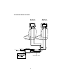
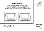
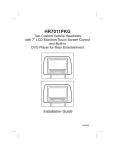
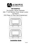
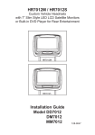
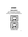
®
HR9000PKG
Two Vehicle Specific Headrests
With 7" LCD Monitors and Built-In
DVD Player for Rear Seat Entertainment
Installation Guide
128-7690
IMPORTANT
An LCD panel and/or video monitor may be installed in a motor
vehicle and visible to the driver if the LCD panel or video monitor
is used for vehicle information, system control, rear or side
observation or navigation. If the LCD panel or video monitor is
used for television reception, video or DVD play, the LCD panel
or video monitor must be installed so that these features will only
function when the vehicle is in ‘park’ or when the vehicle’s parking
brake is applied.
An LCD panel or video monitor used for television reception,
video or DVD play that operates when the vehicle is in gear or
when the parking brake is not applied, must be installed to the
rear of the driver’s seat where it will not be visible, directly or
indirectly, to the operator of the motor vehicle.
This DVD Player incorporates one new feature:
1) A Wireless FMM Interface Box
Please be advised that the wireless modulator will perform well
in most applications. However, in certain applications the quality
of the wireless signal may be less than optimal, resulting in static
or strong station bleed thru.
MATERIALS INCLUDED IN THIS PACKAGE:
1) HR9000PKG System Monitor
M1 Monitor with DVD Player (1pc)
M2 Monitor with DVD Player (1pc)
M1
2) Universal Remote Control
(P/N 136-3785) – (1pc)
M2
3) Infrared 2 Channel Wireless
Headset (P/N IR2CHS) – (2pcs)
4) Hardware Package
Screws – (8pcs)
5) Wireless FMM Interface Box
(P/N 136-4185) – (1pc)
6) Wired Game Controller
(P/N 136-4212) – (1pc)
7) Extension Cable, 8 Pin Din to 8 Pin
Din Conn (P/N 112-3673) – (2pc)
8) Extension Cable, 8 Pin Din to 8 Pin
Din Conn (P/N 112-3659) – (2pc)
9) AV Adapter Cable
(P/N 112B3227) – (2pcs)
10) 8 Pin Din ~ 3 RCA Jack Conn
(P/N: 112-3658) – (1pc)
11) Din Connector Cover – (8pcs)
12) 2 Pin DC Power Cable
(P/N 112-3667) – (1pc)
1
HR9000PKG SYSTEM OVERVIEW
1) The HR9000PKG is a versatile audio / video system with built-in DVD which
includes two monitors, that can accept an Audio / Video input and independent
AUX input. A separate audio output is provided for connecting the FM Modulator
to the vehicle's radio.
2) The M1 Monitor is comprised of a 7" TFT LCD monitor with built-in DVD player
that allows the user to select from DVD, A/V, AUX/GAME sources. The M1
monitor has a built-in infrared audio transmitter (CH A) for use with the supplied
two-channel wireless headphones (CH A). The M1 monitor also has the ability to
select either audio source for output to the FM Modulator to allow audio playback
through the vehicle radio. The built in IR repeater circuitry enables the user to
control the sources via remote control.
3) The M2 monitor is comprised of a 7" TFT LCD monitor with built-in DVD player
that allows the user to select from DVD, A/V, AUX/GAME sources. The M2
monitor has a built-in infrared audio transmitter (CH B) for use with the supplied
two channel wireless headphones (CH B).
4) The monitors will show all of the functions including the FM selection with the
comprehensive OSD. FM functions may also be turned off by selecting the FM
ON / OFF button on the Remote Control.
5) The HR9000PKG System supplies two IR Headphone sets (P/N IR2CHS). The
headsets have an A-B switch that allow the users to select the audio from either
the M1 (CH A) or the M2 (CH B).
6) Using different IR codes, the Master Monitor will only respond to the Remote
Control unit when the Monitor Select (M1) button on remote control is pressed.
The Satellite Monitor will only respond to the Remote Control unit when the
Monitor Select (M2) button on remote control is pressed.
2
7) The M1 and M2 Monitor will accept an audio / video input through the 1/8” jack
and the Game Controller Game Port located on the front of the unit. The audio /
video device could be a video game system, video camera, or other input device.
Note: If the Game Controller is plugged in and an AUX source is plugged in to
the AUX input, the AUX input will override the Game Controller. To use the Game
Controller, unplug the AUX input.
AUX IN
Game Port
8) Pivot the screen until a comfortable viewing angle reached. The internal lock
limits the screen to a maximum adjustment of 30 degrees from closed position,
the headrest itself can be tilted forward to help achieve a comfortable viewing
position.
30 degrees
Inner Ring
Internal Lock
Closed Position
9) Insert disc
10) Eject disc
Disc Label
Insert disc
Eject disc
(M1/M2 Monitor)
(M1/M2 Monitor)
3
VEHICLE PREPARATION:
1) Read the manuals and get familiar with the electrical requirements and
connections.
2) Prepare the vehicle by removing any interior trim necessary to gain access to the
vehicle's wiring as well as all areas where interconnecting wire harnesses will be
located. (Refer to the Installation Procedure). The mounting method, and the
location will vary from vehicle to vehicle, so this manual will only focus for the
installation of the HR9000PKG Master and Satellite Monitors in the supplied
configuration. The best location for the HR9000PKG System components is:
a. Monitors: Vehicle specific Headrest (NOTE: The Master Monitor should be
installed in the passenger position most used.)
b. FM Inter-Connect Box: Under either seat where monitors are located.
3) Locate an accessory power source (+12VDC present when the ignition key is in
the accessory and run positions. 0VDC should be present when the ignition key
is in the OFF position), and a good ground. Generally, these wires can be at the
ignition switch or fusebox.
(NOTE: Ensure that the switched power is fused at the source. Failure to do so
may result in vehicle wiring damage.)
4) Run the wiring harnesses throughout the vehicle as necessary. (Refer to the
Wiring Diagrams on page 6, as well as the wiring instructions for the individual
components and accessory options being installed). Be sure, that all the wiring
is protected from sharp edges and is routed in such a manner that it will not be
pinched, when it is fully installed. Be sure to leave enough slack in the wiring at
each component to allow sufficient working room. Be sure to leave enough
slack in the monitor cables to allow the headrest to move up or down, and the
seat to move backward and forward.
5) Remove all the components from their packaging and then place them in the
vehicle at their respective locations.
6) Install the Headrests:
a. Remove vehicle's original Headrests.
b. Hold the HR9000PKG Headrest above the seat and insert the two cables
into the headrest support tube holes. Make sure that the headrest is in the
correct position (Display facing the rear).
c. Route the cables through the seat back and out the bottom of the seat.
d. Place the Headrest support tubes into the support tube holes while pulling
the cables to remove the slack. Be sure to leave enough slack in the monitor
cables to allow the headrest to move up or down.
4
7) Connect all the components together (electrically) and verify proper operation of
all the system functions.
A) The headrest DIN cables and the FMM inter-connect box DIN cables are color
coded. Connect each headrest cable to the correct color cable on the FMM
inter-connect box. In some vehicles it will be necessary to use the supplied DIN
extension cables to reach from under one seat to the other seat. The DIN
extension cables can be used for either the M1 or M2 monitors. The extension
cables are labeled M1-M2 A and M1-M2B, and are not color coded. When
connecting the extension cables, ensure that the A extension cable is used with
the A monitor cable and the B extension cable is used with the B monitor cable.
B) Extend the wireless FM antenna to its full length and orientate for best
reception. Do not place it on the FMM inter connect box.
C) Connect the DC power jack.
8) After verifying the proper operation of the system cover all of the DIN connectors
with the DIN connector covers and proceed to mount each component.
9) When all the components are mounted, recheck the entire system to be sure it is
functioning correctly. Make sure that no wiring was pinched, or connected
improperly during the final installation.
Wireless FM Modulator
The HR9000PKG is equipped with a built-in wireless FM Modulator*, that allows
you to listen to the DVD audio signal by tuning your vehicle's radio to the selected
frequency, (88.3, 88.7, 89.1, 89.5, 89.9MHz). This feature is accessed by using the
FM transmitter buttons on the remote (ON/OFF, Channel Select).
Whenever the FM modulator is on, broadcast reception on the vehicles radio will
be poor Switching off the FM modulator will allow normal radio reception.
*Note: In certain areas where there are a large number of FM radio stations (e.g. large
cities, urban areas), the reception of the FM signal may not be satisfactory, resulting in
static, distorted sound or signal bleed thru from strong local radio stations. This is not a
defect in the product, but the result of a stronger local radio station overpowering the
wireless FM transmitter in your overhead pod.
If wireless reception is unsatisfactory, an optional wired relay box ( P/N SIRSWB) can
be installed which will improve audio quality. Please contact the installer if this is the
case with your product.
*Note: Extending the wireless antenna beyond its 12-inch length will cause the FM
Modulator to exceed FCC limits for wireless transmission. When installing the unit
position the antenna for the best reception.
5
HR9000PKG WIRING DIAGRAM
M1 Monitor
M2 Monitor
Master Monitor
Satellite Monitor
M1A
M1B
M2A
2 PIN DC POWER CABLE
DC
IN
AV Input
AV Output
INTERFACE BOX
FM ANTENNA
Optional
DIN Extension Cables
Antenna for wireless FM MOD
See antenna note below
6
M2B
For Customer Service
Visit Our Website At
WWW.audiovox.com
Product Information, Photos,
FAQ’s Owner’s Manuals
© 2006 Audiovox Electronics Corp., Hauppauge, NY 11788
128-7690