1
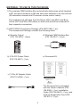
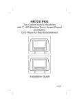
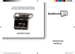
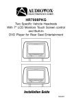
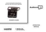
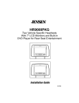
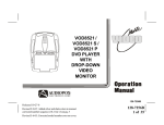
HR7012M / HR7012S
Custom Vehicle Headrests
with 7” Slim Style LED LCD Satellite Monitors
or Built-in DVD Player for Rear Entertainment
S
HR7012M
S
P
HR7012S
Installation Guide
Model DD7012
DM7012
MM7012
128-9047
IMPORTANT NOTICE
Installation of headrest products require careful planning and preparation. Be
extremely careful of seats that have airbags built into them. Keep wiring away
from any air bag wiring (usually identified by yellow connectors and yellow
wire jackets).Damage to air bag wiring can result in personal injury to vehicle
occupants. If you have any questions regarding wire routing or installation in a
vehicle, please contact Audiovox Technical Support at 1-800-225-6074.
When connecting power and ground in a mobile video installation, insure that
the ACC wire is fused at the point where it is connected to the vehicle ACC
wiring. Failure to do so can result in damage to the vehicle if a short circuit
develops between the vehicle connection point and the mobile video product.
An LCD panel and/or video monitor may be installed in a motor vehicle and
visible to the driver if the LCD panel or video monitor is used for vehicle
information, system control, rear or side observation or navigation. If the LCD
panel or video monitor is used for television reception, video or DVD play, the
LCD panel or video monitor must be installed so that these features will only
function when the vehicle is in “park” or when the vehicle’s parking brake is
applied.
An LCD panel or video monitor used for television reception, video or DVD
play that operates when the vehicle is in gear or when the parking is not
applied must be installed to the rear of the driver’s seat where it will not be
visible, directly or indirectly, to be operator of the motor vehicle.
Licensed under one or more of the following patents:
Patent NOS. 7,245,274, 6,899,365, and 6,678,892
2
MATERIAL TO USE IN THIS PACKAGE:
1) The wireless FMM Interface Box automatically determines which headrest
is M1 and which headrest is M2 and sets each headrest to its own function
(IR transmitter channel and IR receiver remote control codes).
The headrests will still have the Pink/Green (MH1 and MH2) and Blue/
Yellow (SH1 and SH2) DIN cables on them and should be connected to
their respective connectors.
2) HR7012PKG Accessories Package (P/N HR7012K) (1 pc)
The Accessories Package contains the following items:
a) Remote Control
(P/N 136-5236) - (2pcs)
d) W
ireless FMM Interface Box
(P/N 136-5237 - (1pcs)
b) 2 Pin DC Power Cable
(P/N 112-3667) - (1pc)
e) Document Kit
c) 12 Pin AV Adapter Cable
(P/N 112-4094) - (1pc)
The Document kit is packaged
with the Owner’s Manual (P/N
128-9046) - (1pc), Installation
Guide (P/N 128-9047) - (1pc), and
Product Registration Card (P/N
132-6751) - (1pc).
3
OPTIONAL:
3) HR7012GP Game Module Package (P/N HR7012GP) (1 pc) OPTIONAL
The Game Module Package contains the following items:
a) Game Controller P1
(P/N 136-5239) - (1pc)
SELECT
S
TA
A
TB
B
c) Game Module
(P/N 136-5238) - (1pc)
START
P1
b) Game Controller P2
(P/N 136-5240) - (1pc)
SELECT
S
TA
A
TB
B
d) Game Module Manual
(P/N 128-9048) - (1pc)
START
P2
Note: The HR7012GP Game Package is the optional accessory package that
allows upgrading to the wireless game source feature.
HR7012 NEW FEATURES:
1)When an optional Game Pack is installed, either monitor can be
designated as “Player 1”. Selection is based on a “first come, first
serve” basis. The second monitor will automatically become
“Player 2.”
2) AUTO “M1 ON” of the HR7012S (M2) monitor(s) when the HR7012
(M1) is turned ON. This is done by selecting “M1” in the Default AUTO
ON/OFF sub-menu. See the Owner’s Manual.
3)AUTO “ON” of the HR7012S (M2) monitor(s) when a video is detected.
this is done by selecting “AV” in the default AUTO ON/OFF sub-menu.
See the Owner’s Manual.
4
HR7012 SYSTEM OVERVIEW:
1) The HR7012 headrest system is available in three configurations; each
can accommodate an optional game pack module. (P/N HR7012 GP)
•Configuration 1: Model DD7012
Two 7” LCD Monitors (800 x 480 resolution) each with a built-in
DVD player (HR7012M)
• Configuration 2: Model DM7012
One 7” LCD Monitor (800 x 480 resolution) with built-in DVD player
(HR7012M)
One 7” LCD Monitor (800 x 480 resolution) (screen only) (HR7012S)
• Configuration 3: Model MM7012*
Two 7” LCD Monitors (800 x 480 resolution) (screen only) (HR7012S)
*Note: The source for this system can be a multimedia head unit, an
external DVD player, Blu-ray Disc player or game console. When
the default Auto/On/Off is set to AV on both screens the screens
will automatically turn on when the source connected to the AV/
IN of the FMM Interface Box provides a video signal to the box.
2)The HR7012M is comprised of a high resolution (800 x 480) LCD screen,
built in DVD player, IR transmitter/receiver, AUX input and USB port.
• Source selection is DVD/USB>M2>A/V-IN>AUX>Media>Game
(optional)
3)The HR7012S is comprised of a high resolution (800 x 480) LCD screen,
IR transmitter/receiver and AUX input.
• Source selection is M1>A/V-IN>AUX> Game (optional)
4)Both units will accept an AV signal through the AUX (RCA) jacks on the
front of the unit.
5)The Wireless FM modulator has 100 channels to choose from via the
remote control or using the front panel controls.
6)The optional game package (HR7012GP) allows either or both users to
play video games.
• Player 1 is on a first come, first served basis.
• If the M2 user selects the game first they are automatically Player 1
and if the M1 user wants to play against the M2 user they become
Player 2.
• If the M1 user selects the game first they are automatically Player 1
and if the M2 user wants to play against the M1 user they become
Player 2.
5
7) AV/USB Connector Access
HR7012M (With DVD)
HR7012S (Screen Only)
S
S
PULL
PULL
DOWN
VIDEO
AUDIO
L
AUDIO
R
USB
P
WIRED
HEADPHONE
AUDIO R
DOWN
VIDEO
AUDIO
L
AUDIO
R
AUDIO L
VIDEO
8) Insert/Eject
20 degrees
Insert/Eject Disc
No Disc Slot
HR7012M
HR7012S
6
VEHICLE PREPARATION:
1)Read the manuals and get familiar with the electrical requirements and
connections.
2)Prepare the vehicle by removing any interior trim necessary to gain access to
the vehicle’s wiring as well as all areas where interconnecting wire harnesses
will be located. The mounting method and the location will vary from vehicle
to vehicle, so this manual will only focus on the installation of the Master
and Satellite Monitors in the supplied configuration. The best location for the
HR7012M/HR7012S System components are:
a) Monitors: Vehicle-specific Headrest
Note:
The M1 monitor should be installed in the passenger position most used.
- The M1 monitor has the pink/green connector.
- The M2 monitor has the blue/green connector.
b) Wireless FM Interface Box: Under either seat where monitors are located.
3)Locate an accessory power source (+12 VDC should be present when the
ignition key is in the accessory and run positions. 0 VDC should be present
when the ignition key is in the OFF position) and a good ground. Generally,
these wires can be located at the ignition switch or fusebox.
Note: Ensure that the switched power is fused at the source. Failure to do so
may result in vehicle wiring damage.
4)Run the wiring harnesses throughout the vehicle as necessary. (Refer to
the Wiring Diagrams, as well as the wiring instructions for the individual
components and accessory options being installed.) Be sure that all the
wiring is protected from sharp edges and is routed in such a manner that it
will not be pinched when it is fully installed. Be sure to leave enough slack
in the wiring at each component to allow sufficient working room. Be sure to
leave enough slack in the monitor cables to allow the headrest to move up or
down, and the seat to move backward and forward.
Note: Do not interfere with air bags or air bag wiring.
5)Remove all the components from their packaging and then place them in the
vehicle at their respective locations.
6)
Install the Headrests:
a) Remove the vehicle’s original Headrests.
b)Hold the Headrest above the seat and insert the two cables into the
headrest support tube holes. Make sure that the headrest is in the correct
position (Display facing the rear).
c)Route the cables through the seat back and out the bottom of the seat.
d)Place the Headrest support tubes into the support tube holes while pulling
the cables to remove the slack. Be sure to leave enough slack in the
monitor cables to allow the headrest to move up or down.
7
7) Connect all the components together (electrically) and verify proper operation
of all the system functions.
a) The headrest DIN cables and the FMM Interface Box DIN cables are color
coded. Connect each headrest cable to the correct color cable on the FMM
Interface Box.
b) Extend the wireless FM antenna to its full length and orientate for best
reception. Do not place it on the FMM Interface Box or near metal.
c) Connect the DC power jack.
8) After verifying the proper operation of the system, mount each component.
9) When all the components are mounted, recheck the entire system to be sure
it is functioning correctly. Make sure that no wiring was pinched or connected
improperly during the final installation.
100 CHANNEL WIRELESS FM MODULATOR:
The HR7011PKG is equipped with a 100 channel built-in wireless FM
Modulator*, that allows you to listen to the DVD audio signal by tuning your
vehicle’s radio to one of the selected frequencies:
(88.1MHz, 88.3MHz, 88.5MHz, 88.7MHz, 88.9MHz, 89.1MHz, 89.3MHz, 89.5MHz,
89.7MHz, 89.9MHZ, 90.1MHz, 90.3MHz, 90.5MHz, 90.7MHz, 90.9MHz, 91.1MHz,
91.3MHz, 91.5MHz, 91.7MHz, 91.9MHz, 92.1MHz, 92.3MHz, 92.5MHz, 92.7MHz,
92.9MHZ, 93.1MHz, 93.3MHz, 93.5MHz, 93.7MHz, 93.9MHz, 94.1MHz, 94.3MHz,
94.5MHz, 94.7MHz, 94.9MHz, 95.1MHz, 95.3MHz, 95.5MHz, 95.7MHz, 95.9MHZ,
96.1MHz, 96.3MHz, 96.5MHz, 96.7MHz, 96.9MHz, 97.1MHz, 97.3MHz, 97.5MHz,
97.7MHz, 97.9MHz, 98.1MHz, 98.3MHz, 98.5MHz, 98.7MHz, 98.9MHZ, 99.1MHz,
99.3MHz, 99.5MHz, 99.7MHz, 99.9MHz, 100.1MHz, 100.3MHz, 100.5MHz,
100.7MHz, 100.9MHz, 101.1MHz, 101.3MHz, 101.5MHz, 101.7MHz, 101.9MHZ,
102.1MHz, 102.3MHz, 102.5MHz, 102.7MHz, 102.9MHz, 103.1MHz, 103.3MHz,
103.5MHz, 103.7MHz, 103.9MHz, 104.1MHz, 104.3MHz, 104.5MHz, 104.7MHz,
104.9MHZ, 105.1MHz, 105.3MHz, 105.5MHz, 105.7MHz, 105.9MHz, 106.1MHz,
106.3MHz, 106.5MHz, 106.7MHz, 106.9MHz, 107.1MHz, 107.3MHz, 107.5MHz,
107.7MHz,107.9MHZ).
This feature is accessed by using the FM transmitter buttons on the remote
(FMM ON/OFF).Whenever the FM Modulator is on, broadcast reception on the
vehicle’s radio will be poor. Switching off the FM Modulator will allow normal
radio reception.
*Note: In certain areas where there are a large number of FM radio stations
(e.g. large cities, urban areas), the reception of the FM signal may not
be satisfactory, resulting in static, distorted sound or signal bleed thru
from strong local radio stations. This is not a defect in the product, but
the result of a stronger local radio station overpowering the wireless FM
transmitter in your overhead pod.
If wireless reception is unsatisfactory, an optional wired relay box (Audiovox P/N
FMDIRB) can be installed which will improve audio quality. Please contact the
installer if this is the case with your product.
8
ELECTRONICS INSTALLATION/REPLACEMENT GUIDE
Install Monitor Unit to Headrest
Monitor Unit
S
S
S
(HR7012M)
S
P
(HR7012S)
Installation
2
1
a
a
b
b
a) Master/Satellite monitor headrest
cable (MH1/SH1) 8 Pin Cable.
b) Master/Satellite monitor headrest
cable (MH2/SH2) 9 Pin Cable.
a) Match MH1/SH1 monitor cable to
M1 headrest connector
b) Match MH2/SH2 monitor cable to
M2 headrest connector
3
4
Rotate the screen up and move the locking tab
to the right to lock the monitor into the headrest.
Install Screws (x4)
9
6
5
Note: Switch off the ACC power during cable and unit installation. Failure to do
so may damage the unit.
Reverse the procedure for removing the electronics.
10
HR7012 SYSTEM WIRING DIAGRAM
HR7012M / HR7012S
Master Monitor
HR7012M / HR7012S
Satellite Monitor
S
Connect to external source such
as Blu-ray player, game console
or multi-media head unit.
112-4208
S
112-4209
P
112-4210
112-4211
12 Pin AV Adapter Cable
GREEN
AV Input
OPTIONAL
Relay Box
AV Output
INTERFACE BOX
FM ANTENNA
RED BLUE
DC
IN
2 PIN DC POWER CABLE
OPTIONAL OF HR7012GP (GAME PACKAGE)
FMDIRB
HR7012GP
Relay Box for wireless FM MOD
See antenna note below
See the instructions supplied with the SIRSWB for installation.
11
YELLOW
If you have any questions regarding this product or
require technical assistance, please call 1-800-225-6074.
© 2012 Audiovox Electronics Corp., Hauppauge, NY
128-9047