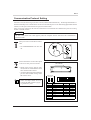
1
User's Manual
Thank you very much for purchasing the CAMM-3
Model PNC-3100.
• To ensure correct and safe usage with a full understanding of this product's performance, please be sure
to read through this manual completely and store it in
a safe location.
• Unauthorized copying or transferral, in whole or in
part, of this manual is prohibited.
• The contents of this operation manual and the
specifications of this product are subject to change
without notice.
• The operation manual and the product have been
prepared and tested as much as possible. If you find
any misprint or error, please inform us.
For the USA
FEDERAL COMMUNICATIONS COMMISSION
RADIO FREQUENCY INTERFERENCE
STATEMENT
This equipment has been tested and found to comply with the
limits for a Class A digital device, pursuant to Part 15 of the
FCC Rules.
These limits are designed to provide reasonable protection
against harmful interference when the equipment is operated
in a commercial environment.
This equipment generates, uses, and can radiate radio
frequency energy and, if not installed and used in accordance
with the instruction manual, may cause harmful interference
to radio communications.
Operation of this equipment in a residential area is likely to
cause harmful interference in which case the user will be
required to correct the interference at his own expense.
Unauthorized changes or modification to this system can void
the users authority to operate this equipment.
The I/O cables between this equipment and the computing
device must be shielded.
For Canada
CLASS A
NOTICE
This digital apparatus does not exceed the Class A limits
for radio noise emissions set out in the Radio Interference
Regulations of the Canadian Department of Communications.
CLASSE A
AVIS
Ce produit numérique ne dépasse pas les limites de la classe
A au niveau des émissions de bruits radioélectriques fixés
dans le Réglement des signaux parasites par le ministère
canadien des Communications.
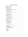
Table of Contents
How to Read This Manual ............................................................................................. i
Typographic Conventions ........................................................................................... ii
To Ensure Safe Use ......................................................................................... iii
Part 1 Startup
1.
2.
3.
4.
5.
Conditions for Installation .................................................................................. 1
Removing the PNC-3100 from the Carton ...................................................... 2
Checking Accessories ......................................................................................... 2
Names of Parts ...................................................................................................... 3
Connecting to a Computer ................................................................................. 7
Connecting the Main Unit, Controller, and Switch Panel ........................................................ 7
Connecting to a Computer ........................................................................................................ 8
Communication Protocol Setting ............................................................................................. 9
6.
7.
8.
9.
Workpiece Set Side ............................................................................................. 10
Cutting Tool Attachment ................................................................................... 11
Power ON ............................................................................................................... 13
Setting the Cutting Origin ................................................................................. 14
Setting the Home Position ...................................................................................................... 14
Setting the Z0 Position ........................................................................................................... 15
10. Cutting Condition Setting .................................................................................. 16
11. Downloading Cutting Data ................................................................................ 18
12. Finishing ................................................................................................................ 19
Part 2 User's Reference
1. Cutting Area .......................................................................................................... 20
2. Coordinate System .............................................................................................. 21
3. Operating Each Function ................................................................................... 22
Replotting (Recutting) ............................................................................................................ 22
Feeding Speed Manual Setting ............................................................................................... 23
Operation Check ..................................................................................................................... 24
Stopping the Cutting Process Immediately ............................................................................ 27
Setting the Tool UP/DOWN Position Manually .................................................................... 28
4.
5.
6.
7.
Maintenance .......................................................................................................... 29
Troubleshooting ................................................................................................... 31
List of CAMM-GL I Instructions ................................................................ 33
Device Control Instructions .............................................................................. 35
Appendix
Supplies .................................................................................................................... 37
Specifications ......................................................................................................... 39
Index .......................................................................................................................... 42
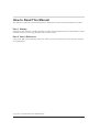
How to Read This Manual
This manual is organized in the following format. Please use it in the way that best matches your needs.
Part 1 Startup
Installation, basic operation, and the procedures to follow when finished cutting are explained here. Please
read this section if you are using the PNC-3100 for the first time.
Part 2 User's Reference
Usage of the PNC-3100’s functions, daily care, and an overview if instruction sets sent from the computer
are explained here.
Copyright © 1993 ROLAND DG CORPORATION
i
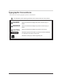
Typographic Conventions
This manual uses certain typographic symbols, outlined below.
This indicates a point requiring particular care to ensure safe use of the product.
DANGER
: Failure to heed this message will result in serious injury or
death.
WARNING
: Failure to heed this message may result in serious injury or
death.
CAUTION
: Failure to heed this message may result in minor injury.
NOTICE
: Indicates important information to prevent machine breakdown
or malfunction and ensure correct use.
: Indicates a handy tip or advice regarding use.
ii
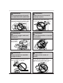
To Ensure Safe Use
WARNING
WARNING
Keep hands away from
moving spindle.
Do not wear gloves, a necktie
or wide-sleeved clothing.
Such items may become
caught in
the
machine.
WARNING
yy
,
À
@
@
À
,
@
À
,
yy
À
@
,
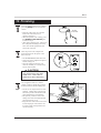
WARNING
Switch off spindle before
attempting to access it.
Do not insert the fingers between
the XY table and base or between
the head and Z cover.
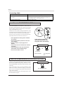
Switch off the spindle before mounting
or removing a tool, and before cleaning. Sudden movement of the spindle
may occur otherwise.
Z cover
Head
The fingers may
be caught.
Base
XY table
{
Â
B
CÃ|BÂ{
WARNING
WARNING
Do not leave the CAMM-3
unattended during operation.
Do not allow persons with no
knowledge of the CAMM-3
near the machine.
,,
,,
@À,y,@Ày
,@Ày
iii
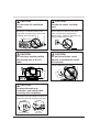
WARNING
WARNING
@AÀÁ,yzACÁÃz|
Do not operate beyond capacity
or subject the tool to undue force.
Fasten the tool and material
securely in place.
The tool may break or fly off in a random direction.
If machining operation beyond capacity is started
inadvertently, immediately switch off the power.
This items may come loose during
cutting and fly off in a random direction.
WARNING
WARNING
Wear dust goggles and mask
during use.
Do not disassemble or remodel
the machine.
Material filings
are scattered
during cutting.
@À,yBÂ{ACÁÃz|
,@BÀÂy{
WARNING
WARNING
Do not install in an unstable
or high location.
Be aware of the center of
gravity.
Do not installation the machine on the
edge of a table, or it may fall.
Do not attach the machine vise or
material too far to either side of the XY
table, or the machine may tip over.
iv
CAUTION
CAUTION
Do not block the ventilation
holes.
Handle the power cord with
care.
Blocking the ventilation holes at the
rear of the controller may prevent heat
radiation and cause fire.
Do not step on or damage the power
cord, or allow heavy objects to be
placed atop it. Failure to heed this may
result in electrocution or fire.
Ventilation holes
X
Y
Z
Z
CAUTION
CAUTION
Do not place anything within
the moving area of the XY
table.
Do not allow liquids, metal
objects or flammables inside
the machine.
Moving area of the XY table
Fire or breakdown may result.
CAUTION
Connect the main unit,
controller, and switch panel
correctly and completely.
The head may descend rapidly if the power is
switched on before all connections are made.
Rear of Controller
Rear of Unit
v
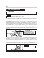
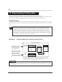
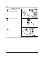
About the Warning Labels Affixed to the Unit
Four warning labels are affixed to the body of this product. The following figure describes the location
and content of these warning messages.
@À,y
,@Àyy,À@
@
À
,
y
@@
ÀÀ
,,
yy
@@
ÀÀ
,,
yy
Do not insert fingers
between the head and Z
cover during operation.
Handle tool with care.
Do not insert fingers
between XY table and
base during operation.
Do not place anything within the moving area of the XY TABLE.
vi
To Ensure Correct Use
NOTICE
Never pile things up on head of the PNC-3100.
This can be very dangerous because of the
possibility of vibration during operation.
vii
Part 1
1
Part
Part
StartUp
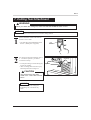
1. Conditions for Installation
WARNING
Do not install the machine in a location where it may tip over, such as at the edge of a
table.
NOTICE
The space shown in the
figure is required for installation.
150mm
(5-15/16")
Install the machine on a stable stand for operation.
Use within a temperature range of 5 to 40°C (41 to 104°F) and within a humidity range of 35 to 80%.
Avoid installing the PNC-3100 in the following locations, as this may result in damage to the machine.
• Avoid places subject to strong electrical noise.
• Avoid excessively dusty or damp places.
• The PNC-3100 generates heat during operation, so avoid poorly ventilated places.
• Avoid places where strong vibration is likely to affect the machine.
• Avoid places exposed to strong direct sunlight.
1226 mm (48-5/16")
100mm
(3-15/16")
263 mm
(10-3/8")
802 mm (31-5/8")
330 mm (13")
209 mm
(8-1/4")
100 mm
(3-15/16")
124 mm
(4-15/16")
100 mm
(3-15/16")
226 mm (8-15/16")
1
* Range of movement
for the XY table
895 mm (35-1/4")
393 mm (15-1/2")
Controller
Switch panel
50 mm 122 mm
(4-13/16")
(2")
CAUTION
Do not place anything
within the moving
area of the XY table.
50 mm
(2")
349 mm (13-3/4")
523 mm (20-5/8")
Main unit
Part 1
2. Removing the PNC-3100 from the Carton
CAUTION
Two or more people are needed to take the PNC-3100 out of the carton.
The main unit weighs 52 kg (114.6 lb.), and the controller weighs 9 kg (19.8 lb.). For this
reason, extreme care should be taken to avoid injury when installing.
Remove all packing material, except for the packing material
underneath the main unit.
A securing board is attached to the unit. Use the 17 mm
spanner included with the unit to remove the four bolts and
detach the board. With one person grasping the carrying bars
at the front of the unit, and the other person grasping the
carrying bars at the rear, lift the unit straight up.
Gently set the unit down at the pre-determined site where the
unit is to be installed.
Remove the controller from the box and set in place.
Four bolts
3. Checking Accessories
Power Code
Collet Chuck (ø6) and Collet Cap
Spanners
(Installed on the spindle.)
(For tool attachment)
Collet Chuck
Collet Cap
Spanner
Hexagonal Wrench : 2
(For removal of the securing board)
30 mm
22 mm
T nuts : 2
(For installing the work attachment)
17 mm
User's Manual
2
Part 1
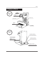
4. Names of Parts
Head
Front of
Unit
Spindle RPM
display
Bellows cover
Spindle switch
Bellows
cover
XY Table
Rear of
Unit
Controller connection
terminal (control signal)
Connection terminal
for Z-axis origin (Z0)
setting-use sensor
(option)
Controller connection
terminal (spindle motor)
Controller connection
terminal (XYZ motor control)
3
Part 1
Power/Error
LED
Controller
Spindle control
Parallel
connector
Power switch
Serial
connector
POWER
OFF
POWER
ON
Option connector
(Refer to page 41.)
Switch panel
connection terminal
Main unit connection
cable (control signal)
Main unit connection
cable (XYZ motor control)
Main unit connection
cable (spindle motor)
Power connector
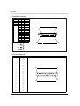
DIP switches
Bottom of
Controller
Switches 1—6
When connected to the computer via the serial (RS232C) standard I/F, set the communication protocols
of the stop bit, data bit, parity check, baud rate and
handshake switches to match the settings at the
computer side.
ON
State of DIP SW
ON or OFF
ON
1
2
3
4
5
6
7
8
9 10
OFF
Switch
Function
OFF
ON
1 bit
2 bits
1
Stop bits
2
Data bits
8 bits
7 bits
3
Parity check
ODD
EVEN
4
Parity check
DISABLE
ENABLE
5
Baud rate
9600 baud
4800 baud
6
Handshake
DTR
Xon/Xoff
7
Spindle revolution
8
Over area
9
10
ON
OFF
CONTINUE
PAUSE
Switch 7
Setting switch 7 to ON prohibits spindle rotation
regardless of other settings.
Set switch 7 to ON to perform engraving without
rotating the spindle.
Switch 8
Switch 8 allows the operator to select CONTINUE or
PAUSE in the cutting operation when PNC-3100
movement has exceeded the coordinates set for the
specified cutting range.
Not used (always OFF)
Switches 9 and 10
These switches are not used. Make sure they are set
to OFF.
4
Part 1
Switch
panel
X-AXIS
Y-AXIS
Z -AXIS
JOG
X
Y
Z
ENTER
REPLOT
SPINDLE TEST
SENSOR
ON / OFF
ON / OFF
BUFFER
Z1
Z0
Z2
HOME
JOG
VIEW
Z
CLEAR
PAUSE
ON
X-AXIS
OFF
XYZ Coordinate
Display
This display shows the coordinate values of each axis in 1/100 mm
units. For the X and Y axes, the home position coordinates (refer to
page 14) are (0, 0). For the Z axis, Z0 (refer to page 15) is displayed
as "0."
REPLOT Key
This keys carries out replotting (recutting) when cutting data is
present in the PNC-3100 data buffer.
ENTER Key
In combination with the [Z0] , [Z1] , [Z2] and [HOME] keys, the
key designates the positions of Z0, Z1, Z2 and HOME. Also, if this
key is pressed when PAUSE is ON, the moving speeds in each axis
direction are shown on the XYZ coordinate display.
Z Axis Position
Keys
These keys are used to set the positions of Z0, Z1 and Z2 in
combination with the [ENTER] key. Also, the tool is moved to the
ZO, Z1 or Z2 position when the appropriate key is pressed. In the
interests of safety, movement to Z1 does not begin until the [Z1] key
is pressed for 0.5 seconds.
HOME Key
This key is used to set the HOME position (refer to page 14) in
combination with the [ENTER] key. Also, if you continue pressing
this key for approx. 0.5 seconds, the tool is moved to the HOME
position.
SENSOR Key
In the case that Z0 setting is performed using the optional sensor, this
key functions as the sensor ON/OFF switch.
VIEW Key
If this key is pressed for 0.5 seconds or more, the spindle raised and
the XY table moves toward the front of the unit and stopped.
* This figure is X
Coordinate Display.
5
Part 1
PAUSE Keys
When the [PAUSE ON] key is pressed while operating under the
instruction of a computer, the PAUSE LED comes ON and the PNC3100 enters the temporary stop condition and all cutting operations
are interrupted. When the [OFF] key is pressed, the temporary stop
condition is cancelled and machine resumes cutting from the position at which operation was interrupted.
PAUSE LED
This LED comes ON when the PNC-3100 enters the temporary stop
condition as a result of the [PAUSE ON] key being pressed. This
LED goes OFF when the temporary stop condition is cancelled by
pressing the [OFF] key.
BUFFER CLEAR
Key
If this key is pressed for 0.5 seconds or more, erasing all data
transferred from the computer.
SPINDLE TEST
ON/OFF Key
When this key is pressed while the spindle revolution stops, the
spindle is forced to rotate. When this key is pressed while the spindle
is revolving, the revolution stops.
JOG Keys
These keys move the tool in the + or - directions along the X, Y and
Z axes. Perform rough position using these keys and then make
delicate adjustments to the tool position using the jog handle. The
tool moves approx. 30 steps (0.3 mm ( 0.12")) each time a key is
pressed. The jog handle can move the tool one step (0.01 mm
(0.00039")) at a time. Holding down the jog key for the X or Y
direction allows rapid movement in that direction when the spindle
is not rotating.
Because X, Y and Z movements are independently controlled, the
keys for movement along each axis can be pressed simultaneously.
In this manual, the Z-axis Jog key is represented in [ (Z)] or [ (Z)].
Z
JOG Handle
This handle moves the tool position on the X, Y or Z direction in units
of 1 step (0.01 mm (0.00039")). Select the axis along which
movement is desired using the [JOG] key. The jog handle can then
move the tool along the selected axis
JOG Handle Select
Key
This key is used to select the axis along which the jog handle moves
the tool. This key is referred to as the [JOG] key in this manual.
JOG Handle LEDs
These LEDs provide an indication of the currently selected jog
handle axis.
6
Part 1
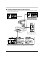
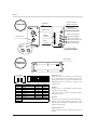
5. Connecting to a Computer
Connecting the Main Unit, Controller, and Switch Panel
NOTICE
Connect the cables only when the PNC-3100 and the computer power sources are OFF.
Ensure that the power supply voltage is within ±10% of the machine's rated voltage.
Securely connect the power cord and cables for computer input and output to prevent them from coming loose
or causing poor contact during use.
Switch panel
Controller
Main unit
Power cord
Power connector
7
Part 1
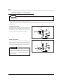
Connecting to a Computer
NOTICE
When connecting to a computer for the first time, be sure to perform an operation check to make sure the unit is
operating correctly.
Connect the PNC-3100 to the computer using the cable.
The cable for computer connection is optional. Please purchase the appropriate cable for the type of computer and
software used .
Parallel Connection
Connect the printer-use connector of the computer and
the parallel connector at the rear of the controller using
a parallel cable. Fix the cable securely in place using
the lock-use pins at both edges of the connector.
Lock-use pin
Parallel
connector
Lock-use pin
Serial Connection
Connect the RS-232C terminal of the computer and the
serial connector at the rear of the controller using a
serial cable. Fix the cable securely in place by tightening the screws attached to the cable using a screwdriver.
Screw
NOTICE
Serial
connector
When making a serial connection, set the same
communication protocol (parameters) for both the
computer and for the PNC-3100. Refer to page 9
for setting the PNC-3100 communication parameters (protocol).
Screw
8
Part 1
Communication Protocol Setting
In the PNC-3100, the interface type (Parallel or Serial) is differentiated automatically. The distinguished interface is
memorized until the power is turned OFF. It can not be varied while the power is ON. When changing the differentiated
interface, turn the power OFF and then ON again, then transmit data.
In the case of serial connection, the controller sends and receives data under the communication protocols set using
the PNC-3100 DIP switches.
NOTICE
The PNC-3100 cannot receive data properly when the computer software and PNC-3100 communication
parameters differ.
2
• The POWER/ERROR LED will turn
off.
Set the DIP switches on the bottom panel
to the ON or OFF position as needed.
DIP switches
• Setting of the stop bit, data bit, parity
check, baud rate and handshake can be
done with these DIP switches.
• An object with a fine tip such as a ballpoint
pen will make ON/OFF settings of the
DIP switches easier.
State of DIP SW
ON or OFF
ON
1
If the power was set to ON then switch it to
OFF.
Please use ample caution to avoid
breaking the DIP switches by applying unnecessary force.
ON
Switch
2
3
4
5
6
7
8
9 10
OFF
ON
1
Stop bits
1 bit
2 bits
2
Data bits
8 bits
7 bits
3
Parity check
ODD
EVEN
4
Parity check
DISABLE
ENABLE
5
Baud rate
9600 baud
4800 baud
6
Handshake
DTR
Xon/Xoff
7
Spindle revolution
8
Over area
9
10
9
1
OFF
Function
ON
OFF
CONTINUE
PAUSE
Not used (always OFF)
Part 1
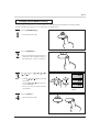
6. Workpiece Set Side
WARNING
Detachment of the material during operation is extremely dangerous. Follow the
procedure described below to fasten the material in place securely.
NOTICE
Do not place anything on the XY table except material to be cut.
This section is an explanation of the cutting workpiece attachment method when an optional machine vice ZV-1 is used.
If employing an alternative attachment method, fix the workpiece firmly in place using the following explanation for
reference.
Under the standard workpiece attachment method, a block is attached to the vice, then the workpiece is fixed to the
block with double-sided adhesive tape. This is the most suitable method when cutting comparatively small workpieces.
For the fixing-use block, it's better to choose a workpiece that can be cut and aligned horizontally with precision. (So
that after attachment with the vice, accuracy can be improved when the surface is cut.) When cutting complicated
shapes, it can be difficult to fix the workpiece to accommodate the cutting process. But with this method you can fix
the workpiece setting position by cutting the block itself to the required shape.
Before fixing the workpiece in place, take away any foreign matter such as cutting waste from the surface of the fixinguse block. If foreign matter remains, the workpiece may not be properly fixed and also the finished dimensions may
not be precise.
CAUTION
Workpiece
Use caution to avoid injury when
attaching or changing a vise or
material while a tool is installed.
Material fixing-use block
As an alternative, it is possible to attach the workpiece to the vice directly. Because no fixing-use block is utilized,
this method is capable of accommodating larger workpieces. In addition, attachment and detachment are easy.
However, this method is not suitable for very complicated shapes or for cases where the strength of the part held in
the vice is weak.
In cases where the workpiece is attached to the vice directly, be careful to adjust the cutting depth (the total Z axis
feeding amount) so that the part of the workpiece held in the vice is not cut. If the tool cuts the vice, the cutting edge
of the tool will be damaged and it will be impossible to use. Also, in the case of a very thin tool, the cutting edge may
break and become very dangerous.
NOTICE
Take care to avoid cutting the vise.
Workpiece
10
Part 1
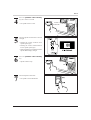
7. Cutting Tool Attachment
WARNING
When you attach the cutting tool, make sure that the SPINDLE switch is OFF.
NOTICE
Use the correct tool for the material to be cut and the cutting method.
1
2
Set the SPINDLE switch on the front of
the PNC-3100 to OFF.
LED
• The LED lamp in the SPINDLE switch
flashes. (When power is applied.)
If a cutting tool has been installed, remove
it. Use the two spanners provided to
loosen the collet cap.
• To keep the cutting tool from falling out,
loosen only slightly.
• After loosening, then loosen the cap by
hand and pull out the cutting tool.
Collet cap
Spanners
CAUTION
The tool becomes hot when
metal is cut. Take care to avoid
burns.
NOTICE
Be careful to keep the cutting tool
from falling out, or the blade may
break.
11
Part 1
If the collet chuck has not been installed,
install it. Fit the collet chuck in the
collet cap as shown in the figure, and
tighten provisionally on the spindle.
• Lightly tighten the collet cap to
prevent it from falling off.
• The collet chuck included with the unit
has a diameter of 6 mm (1/4"). If the
shank diameter of the cutting tool does
not match the diameter of the chuck,
replace with a chuck of matching
diameter (chucks with diameters other
than 6 mm (1/4") are sold separately).
• The collet chuck can easily be
removed from the collet cap by
twisting it while pulling.
3
Collet chuck removal
Collet
chuck
Collet
cap
Adjust the height of the inserted tool as
needed and tighten the collet cap by
hand.
Collet
cap
• Tighten the cutting tool enough to
prevent it from falling out.
NOTICE
Use caution to prevent the cutting
tool from falling out, otherwise the
cutting tool may be damaged.
4
Tighten the collet cap using the two
accessory spanners. Securely fasten the
cutting tool to the spindle.
CAUTION
Spanners
A cutting tool not securely
fastened to the spindle is
extremely dangerous.
Make sure the collet cap is
securely tightened!
NOTICE
Do not install only the collet chuck
(without a cutting tool) and tighten
with a spanner. Doing so may make
it impossible to install a cutting tool
the next time the device is used.
12
Part 1
Set the SPINDLE switch to ON.
5
• The LED lamp in the SPINDLE switch
lights up. (When power is applied.)
8. Power ON
CAUTION
Connection all cables securely. Normal
operation may be impossible if the power is
switched on while connections are
incomplete.
Press the POWER switch on the front of the controller
setting the power to ON. (In the PNC-3100 after setting
the power to ON, proceed to turn on power to the
computer.)
13
Part 1
9. Setting the Cutting Origin
The PNC-3100 are suitable for use with a versatile range of workpiece shapes and a wide variety of tools, so determine
the standard points for cutting each time a new workpiece is set. Set the home position (origin point for X an Y axes)
and Z0 (Z axis origin point). (If these points can be set with your current software, they should be set using the software.)
Setting the Home Position
The home position is the point that becomes the origin point in the X and Y directions. Usually, this point is set at the
front left corner of the fixed workpiece. The setting method explained here, uses the left, bottom corner (nearest the
operator) of the workpiece as the home position.
The home position points are registered in the PNC-3100 memory right after power is turned on and before
power is turned off.
1
2
3
Move the cutting tool tip close to the
lower (nearest operator) left corner of
the workpiece, using the [ ] [ ] [ ]
[ ] [ (Z)] [ (Z)] jog keys.
Move the tool little by little with the [JOG]
key and the jog handle.
• Line up the cutting tool tip with the lower
left corner of the workpiece.
Press the [ENTER] key while pressing the
[HOME] key.
• Both the X and Y axis indicators on the
coordinate display are displayed as "0".
• Once the home position is registered in
the PNC-3100 it remains in the memory
even when the power is turned off. The
home position point will remain registered in the memory until a new home
position setting is made.
While
pressing
14
Part 1
Setting the Z0 Position
With some software, Z1 (the tool-down position) and Z2 (the tool-up position) are set by commands
from the software (see page 28 for an explanation of Z1 and Z2).
Right after switching on the power, Z0 is set at the mechanically uppermost position. This means
that if cutting data is sent from such software without setting Z0 first, the software will attempt to set
Z2 at a position higher than the uppermost mechanical point, and an error will occur. (The POWER/
ERROR LED flashes and operation pauses.) Be sure to set Z0 before sending cutting data.
If an error occurs, stop the transmission of data from the computer and cancel the error by clearing
the buffer or by switching the power to the PNC-3100 off and on again (see page 32).
The home position is the point that becomes the origin point in the X and Y directions. Usually, this point is set at the
front left corner of the fixed workpiece. The following explains the method for setting the workpiece surface Z0
position. The highest position mechanically, is set right after the power is turned on.
1
2
Move the cutting tool tip close to the
surface of the workpiece, using the [
[ ] [ ] [ ] [ (Z)] [ (Z)] jog keys.
]
Select the Z axis with the [JOG] key
and move the cutting tool a little bit at a
time with the jog handle.
Tool
• Line up the cutting tool tip with the
surface of the workpiece.
Z0
Workpiece
3
Press the [ENTER] key while pressing the
[Z0] key.
• The Z axis indicator on the coordinate
display are displayed as "0".
While
pressing
15
Part 1
10. Cutting Condition Setting
WARNING
When using a small-diameter tool, do not apply an excessive feed speed or cutting-in
amount while cutting, or the tool may break or fly off.
Before you begin the actual cutting process, the cutting conditions such as the revolution speed of the spindle motor
and the feeding speed of each axis must be designated according to the quality of the workpiece and the type of tool
used. There are several deciding factors to be taken into account when designating the cutting conditions.
1. The quality of the workpiece
2. The type of tool used
3. The diameter of the tool used
4. The cutting method
5. The cutting shape
Designate the cutting conditions in consideration of the above factors by performing the following three PNC-3100
setting operations.
1. The spindle motor revolution speed (tool revolution speed)
2. The feeding speed (tool moving speed)
3. The cutting-in amount (depth of one cutting operation)
Note : When settings have been made with both the software and the PNC-3100, the last settings made have priority.
In this manual, these three conditions are called the cutting conditions. The characteristics and points to consider for
each of these conditions are as follows.
Item
Characteristics/Points to Consider
The bigger this number, the faster the cutting speed. However, if this number is too large,
the work surface may melt or burn due to excessive friction. Conversely, if this number is
Spindle motor
revolution speed
made smaller, the time taken for cutting becomes too longer. Generally speaking, the
entire cutting speed is determined by the cutting edge speed, so the smaller the tool
diameter, the higher the spindle revolution speed requied. (Note : Refer to page 4 for
details on engraving without rotating the cutting tool.)
Revolution speed : 3000—8000 rpm
When the feeding speed is high, processing becomes rough and flash marks tend to remain
Feeding speed
on the cut surface. On the other hand, when the feeding speed is slow, processing takes
more time. Be careful because a slower feeding speed does not always result in improved
finishing.
When the cutting-in amount is deeper, the cutting speed increases, but the cutting-in
Cutting-in amount
amount is limited by the quality of the workpiece. In cases where the required depth can
not be cut at once, repeat cutting several times to depth that does not breach the limit.
Manual Setting of Cutting Conditions
The cutting conditions can be set manually according to the method described below.
If the cutting conditions can be set with your current software, this is a faster and more efficient method than manual
setting. It makes no difference when you come to construct a program. The following method is appropriate for making
delicate halfway adjustments to conditions previously set using software, etc.
Feeding Speed
Feeding speed setting is performed via a switch panel key operation. Refer to page 23; "Feeding Speed Manual
Setting."
16
Part 1
Spindle Motor Revolution
Speed
HIGH
The spindle motor revolution speed can be set by
turning the spindle control knob on the controller.
Monitor the speed indicated on the Spindle RPM
Display while making this setting.
Spindle Speed Ranges
3,000 to 8,000 rpm
Cutting-in Amount
The cutting-in amount is set by setting Z1. (Refer to page 28; "Setting the Tool Up/Down Position Manually.")
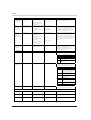
Cutting Condition Setting Examples
The chart below contains reference examples of the appropriate cutting conditions for several types of workpiece
material. In the case that the conditions are input using software or when constructing your own programs, set the
cutting conditions with reference to the chart. However, because conditions differ depending on tool sharpness and
workpiece hardness, cutting performance may not always be optimal when adhering to the conditions specified below.
In such a case, delicate adjustment should be performed at the time of actual cutting.
Workpiece
Modeling wax
(option)
ABS plastic
Acrylic resin
Aluminum
Brass
Tool
(option)
Spindle revolution speed
Cutting-in amount
(ø x depth)
Feeding speed
(mm/sec.)
ZHS-300
ZHS-600
8000
6000
3 x 3.0
6 x 6.0
5—12
4—10
ZUS-600
6000
6 x 6.0
4—8
ZHS-100
ZHS-300
8000
8000
1 x 0.5
3 x 3.0
2—8
8—10
ZHS-600
6000
6 x 4.5
5—8
ZUS-600
ZUB-300
6000
6000
6 x 4.0
3.0 x 3.0 (radius x depth)
4—8
5—8
ZEC-100
ZHS-100
8000
8000
0.5 (depth only)
1 x 0.5
4—10 (Z axis : 2)
7—10
ZHS-300
8000
3 x 1.5
4—6
ZHS-600
6000
6 x 2.0
2—4
ZUS-600
6000
6 x 3.0
2—3
0.3 (depth only)
2—8 (Z axis : 2)
ZEC-100
8000
ZHS-300
8000
0.5 (depth only)
3 x 0.5
2—6 (Z axis : 2)
1—2
ZHS-600
ZUS-600
6000
6000
6 x 0.5
6 x 0.3
1—2
1—2
ZUB-300
8000
3.0 x 0.2 (radius x depth)
1—2
ZHS-300
8000
3 x 0.5
1—3
ZHS-600
6000
6 x 0.5
1—2
ZUS-600
6000
6 x 0.5
1—2
ZUB-300
8000
3.0 x 0.3 (radius x depth)
1—2
17
Part 1
11. Downloading Cutting Data
The PNC-3100 performs cutting after receiving cutting data from the computer (software).
In this section, general matters related to data output are explained. Refer to this section when carrying out data output.
For details of the cutting data output method, refer to the operation manual for the software used.
Software Setting
In cases where cutting is controlled by generally available application software, select PNC-3100 as the output
equipment setting. In cases where it is not possible to select PNC-3100 , select PNC-3000 or PNC-2700 or PNC-2500R/
2500.
Identification of the interface type (connected with computer) is done automatically in the PNC3100. There is no need for the user to select the interface type. For serial connections, the communication parameters (protocol) must be set before sending cutting data (refer to page 9 for details.)
The PNC-3100 uses the CAMM-GL I instruction set. When setting the output device software,
select a type that is compatible with CAMM-GL I. (Modes 1 and 2 of CAMM-GL I are identified
automatically. To change parameters during an ongoing instruction set, turn off the power once and
then, after turning on the power, commence sending data.)
[Example]
Selecting application software output device
Output device selection
Select PNC-3100. If it is
not listed, select PNC3000 or PNC-2700 or
PNC-2500R/2500.
Select either the parallel
(Centronics) or the serial
(RS-232C) interface.
Choose the one that the
host computer and the
PNC-3100 are connected
by.
Device name
△
[PNC-3100] PNC-3100
PNC-3000
PNC-2700
PNC-2500
▽
Interface
[RS-232C]
Centronics
RS-232C
Protocol
Baud rate
Data bit
Stop bit
Parity
Handshake
9600
4800
2400
1200
600
OK
* PNC-3100 communication protocol setting is performed by setting the DIP
switches on the controller bottom. Refer to page 9 for details.
NOTICE
Clean the unit and its surrounding while in operation. Avoid using an air gun or cloth for cleaning; use a vacuum
cleaner or brush.
18
Part 1
12. Finishing
1
2
When all cutting operations are complete
press the [VIEW] key for at least half a
second.
At least
0.5 seconds.
• Raise the cutting tool, move the XY
table to the outer left (close to
operator) and stop it.
• When the spindle is still rotating, press
the [SPINDLE TEST ON/OFF] key
in order to stop it.
• After turning off the power, removal of
the workpiece and cutting tool will be
easier now that the spindle has been
moved out of the way.
After the power to the computer has
been turned off, turn the power to the
PNC-3100 off.
• The POWER/ERROR LED turns off.
• Next remove the completed workpiece
and the cutting tool.
• Store the cutting tool that was just
removed, carefully so it will be ready
for use when needed.
CAUTION
The tool becomes hot when
metal is cut. Take care to
avoid burns when detaching.
3
Use an appliance such as a vacuum
cleaner to remove cutting chips and grit
from the machine and surrounding area.
• Do not use an compressed air for such
cleaning. Cutting chips in the air may
attach to a portion of the machine and
cause malfunctions or breakdowns.
• Be especially careful to remove the
cutting waste from around the pleated
part of the bellows cover.
• Keep the PNC-3100 and its accessories
in neat and proper order and use care
to ensure normal work operations are
carried out safely.
Bellows
cover
Bellows
cover
19
Part 2
Part
Part
2
User's Reference
1. Cutting Area
The maximum cutting area of the PNC-3100 is 250 mm × 150 mm × 150 mm (9-13/16" × 5-7/8" × 5-7/8"). Converting
this into coordinate values based on the machine's step number (1 step = 1/100 mm (0.00039")), we obtain the
coordinate system; (x, y, z)=(25000, 15000, 15000).
The actual available cutting area is subject to restrictions according to the length of the attached tool, the X table position
at which the workpiece is fixed, and the vice height (in the case that the vice is used); and in some cases it may be larger
than the maximum operating area.
150 mm (5-7/8")
250 mm
(9-13/16")
150 mm (5-7/8")
20
Part 2
2. Coordinate System
The PNC-3100 employs three separate coordinate systems (described below) according to the application or purpose
of use.
Machine Coordinate
Under the machine coordinate system, the coordinates
are determined mechanically against the PNC-3100.
This system forms the basis of the "work coordinates"
and "user coordinates" which are explained later. The
machine coordinate range is equivalent to the PNC3100's maximum operating range. The point to which
the XY table and head move when the power is turned
ON is the origin of the machine coordinate system (x, y,
z)=(0, 0, 0). (The origin is fixed.)
The machine coordinate system basic unit is fixed as one
step = 1/100 mm (0.00039").
Z
The origin
of the machine
coordinates
Y
X
Work Coordinate
The origin of the machine coordinate system is fixed, but
there is a coordinate system in which the origin can be
moved relative to the machine coordinate system. This
system is called the work coordinate system.
In the work coordinate system, the home position is the
XY origin and Z0 is the Z axis origin. The origin of the
work coordinates can be set by setting the home position
(the XY axis origin) and Z0 (the Z axis origin).
The origin of the work coordinates is the standard point
for cutting against the attached workpiece.
The work coordinate system basic unit is fixed as one
step = 1/100 mm (0.00039").
User Coordinate
Z
The origin
of the work
coordinates
Y
X
* If you are using application software, there is no
need to worry about the user coordinate system.
You can ignore it completely.
Under the machine coordinate system and the work coordinate system, the unit value is fixed. In contrast, the user
coordinate system allows the user to set the unit value freely. (However, the unit value can be set only for the XY axis.
The Z axis unit value cannot be set.)
The user coordinate system unit is determined by replacing (converting) the work coordinate system unit with the user
coordinate system unit. Also, the user can set the cutting data output to the position of the basic point of the workpiece
on the XY axis. This operation is called scaling. It can be performed with the use instructions. For further details,
please refer to the optional CAMM-GLI Programmer's Manual.
If scaling is not performed, the user coordinate system unit and the work coordinate system unit are equivalent.
21
Part 2
3. Operating Each Function
Replotting (Recutting)
Pressing the [REPLOT] key calls up the cutting data stored in the PNC-3100's data buffer and executes the replotting
procedure. The data buffer is the place where data received from the computer is stored temporarily. (The data in the
data buffer can be erased by switching off the power or holding down the [BUFFER CLEAR] key for at least 0.5 sec.)
When replotting is executed, the entire data content of the data buffer is called up. When you perform replotting, clear
the data from the data buffer before sending the cutting for replotting from the computer.
1
Press the [BUFFER CLEAR] key for at
least 0.5 seconds.
X-AXIS
000
At least
0.5 seconds.
• The data buffer is cleared.
• When data in the buffer is erased, the
coordinate display for the Y axis begins
to flashes.
Y-AXIS
000
Z -AXIS
000
The Y-axis coordinate
display flashes.
2
Download the cutting data using the operating software of computer.
Download Data
• When cutting is finished, replace the
workpiece.
• If necessary set the home position (refer
to page 14) and Z0 (refer to page 15).
Device Name
Protocol
PNC-3100
Baud rate
Data bit
Stop bit
Parity
Handshake
Interface
RS-232C
: 9600
:8
:1
: None
: Xon/Xoff
Confirm the settings, then click "OK".
Press the [REPLOT] key.
3
• Replot (recutting) will start.
22
OK
CANCEL
Part 2
Feeding Speed Manual Setting
At times when speed cannot be set with the software or when adjusting the speed during an ongoing cutting
operation use the panel switch keys to set cutting tool movement speed.
Press the [PAUSE ON] key.
1
• PAUSE LED comes ON.
Press the [ENTER] key.
2
3
• The current feeding speed of each axis is
displayed on the coordinate display of
the switch panel. (Units are in mm/sec.)
Press the Jog key ([
[ (Z)], [ (Z)]).
], [
], [ ], [ ],
X-AXIS
30
Y-AXIS
• Use the [ ], [ ], [ (Z)] jog keys for fast
movement.
Use the [ ], [ ], [ (Z)] jog keys for
slow movement.
• The X axis and Y axis speeds cannot be
set separately.
30
Z -AXIS
10
Feeding speed will
change.
Press the [OFF] key.
4
• PAUSE LED goes OFF.
23
Part 2
Operation Check
If the PNC-3100 operates abnormally, perform an operation check according to the instructions below. If, as a result
of the check, no abnormality is found, check for abnormalities in the computer, software or cable.
WARNING
Remove the tool, workpiece and vice before beginning the operation check.
1
Turn the power ON. (If the power has
already been turned on, turn it off and then
back on again.
• The POWER/ERROR LED will light
up.
Press the Jog key.
2
3
• Move the XY table to the front, back, left
or right with the [ ], [ ], [ ], [ ]
keys.
• Move the spindle up or down with the
[ (Z)], [ (Z)] jog keys.
Press the [VIEW] key for at least 0.5 seconds.
• The spindle rises and the XY table moves
toward the front of the unit.
At least
0.5 seconds.
24
Part 2
4
5
6
Press the [SPINDLE TEST ON/OFF]
key for at least 0.5 seconds.
At least
0.5 seconds.
• The spindle starts to rotate.
Turn the Spindle Control knob to the left
and right.
• Rotating the control clockwise raises
spindle speed (rpm).
• Rotating the control counterclockwise
lowers spindle speed (rpm).
• Make sure that the speed indicated on the
Spindle RPM Display changes.
HIGH
Press the [SPINDLE TEST ON/OFF]
key.
• Spindle rotation stops.
STOP
Turn the Spindle switch OFF.
7
• The spindle switch LED flashes.
25
Part 2
8
Press the [SPINDLE TEST ON/OFF]
key for at least 0.5 seconds.
At least
0.5 seconds.
• The spindle does not rotate.
Turn the Spindle switch ON.
9
• The spindle lights up after flashing.
Turn the power OFF.
10
• The POWER/ERROR LED turns off.
This completes the operation check. If no abnormalities are detected in the course of this check, the
PNC-3100 is normal.
26
Part 2
Stopping the Cutting Process Immediately
In the case that you begin cutting and then find that you have sent the wrong cutting data, perform the following
operation.
Press the [PAUSE ON] key.
1
2
• PAUSE LED comes ON.
• The unit stops after completing the cutting operation in progress.
Stop the transfer of data to the PNC-3100
by operating software of computer.
Download Data
• For details of the data transfer stop
method, refer to the manual of the computer or software you use.
Device Name
Protocol
PNC-3100
Baud rate
Data bit
Stop bit
Parity
Handshake
Interface
RS-232C
: 9600
:8
:1
: None
: Xon/Xoff
OK
CANCEL
Download data now. Click "CANCEL", then stop to download.
3
Press the [BUFFER CLEAR] key for at
least 0.5 seconds.
X-AXIS
At least
0.5 seconds.
• The data buffer is cleared.
• When data in the buffer is erased, the
coordinate display for the Y axis begins
to flashes.
000
Y-AXIS
000
Z -AXIS
000
The Y-axis coordinate
display flashes.
Press the [OFF] key.
4
• PAUSE LED goes OFF.
• Download the current of data to the PNC3100 by operating software of computer.
• If necessary set the home position (refer
to page 14) and Z0 (refer to page 15).
27
Part 2
Setting the Tool Up/Down Position Manually
The cutting tool up position (Z2 point) and down position (Z1 point) are normally set with the software. If they cannot
be set with your current software then set them manually using the keys on the switch panel. Setting is done by
determining the cutting tool up position Z2 and down position Z1.
Tool
Tool up position
Tool down position
1
2
3
Z2
Z0
Z1
Workpiece
Move the cutting tool tip to a position near
Z1 (or Z2) with the jog keys [ (Z)], [ (Z)].
• Move the spindle to a spot away from the
workpiece when setting Z1.
Select the Z axis with the [JOG] key and
move the cutting tool a little bit at a time
with the jog handle.
Tool
• Line up the cutting tool tip at the height
needed for Z1 (or Z2).
• The coordinates can be set at the same
time while watching the coordinate display table.
Z2
Z1
Press the [Z1] key (or [Z2] key) while
holding down the ENTER key.
• Z1 (or Z2) has now been set.
While
pressing
28
Workpiece
Part 2
4. Maintenance
WARNING
When cleaning the PNC-3100, make sure that the main unit's power is OFF.
Cleaning the Main Unit
When the arm of the main unit (excluding the display section), controller or switch panel (excluding the display section)
becomes dirty, use a cloth moistened with water or neutral detergent solution to wipe it lightly.
Use a dry cloth to wipe the display section on the main unit and switch panel.
Cleaning After Operation
After cutting work is completed, use a vacuum cleaner to clean the PNC-3100 main unit and the surrounding area of
cutting dust. Be especially careful to remove the cutting waste from around the pleated part of the bellows cover. If
necessary, move the XY table to the front and rear, and clean the entire cover. Except when moving the XY table, carry
out all cleaning work with the PNC-3100's power OFF. Also, if the PNC-3100 is used in a room equipped with a
ventilation fan, rapid clogging by filing may occur. Perform cleaning during operation.
Bellows cover
Bellows cover
The above two cleaning operations are the only maintenance procedures that the customer needs to
perform. Oil supply and other maintenance are not required.
Checking the Spindle Motor
Operate the spindle motor alone, with no tool installed or material loaded. If the rotation speed is uneven or marked
noise is produced, be sure to contact a service technician.
29
Part 2
Display of Spindle Rotation Time
The PNC-3100 has a function for the displaying the total rotation time of the spindle. Because the brushes and other
components of the spindle motor are parts that wear out and require inspection at periodic intervals. This display is designed
to serve as a guide for such inspection. (The motor brushes require replacement approximately every 500 hours.)
Turn the power ON.
1
• The POWER/ERROR LED will light
up.
Press the [PAUSE ON] key.
2
3
• PAUSE LED comes ON.
Press the [SPINDLE TEST ON/OFF]
key.
X-AXIS
92
• The total rotation time (in hours) of the
spindle appears on the coordinate display while the key is held down.
• When the key is released, the screen
returns to a coordinate display.
Y-AXIS
000
Z -AXIS
000
* Appears on the X
coordinate display.
Recommended Service Checking
The PNC-3100 is a precision machine. In order to maintain it safely for operation over the long term, we recommend
that it should be checked by a qualified serviceman. There is a charge for this service. Please take note of this in
advance.
Maintenance to Be Performed by a Service Technician
- Inspection and maintenance at every 500 hours of spindle rotation time (refer to “Display of Spindle Rotation Time”)
- Checking and adjustment of the spindle belt
- Replacement of consumable parts (brushes, spindle belt, spindle motor, and spindle unit)
30
Part 2
5. Troubleshooting
When the PNC-3100 does not work ...
The following causes should be considered.
PNC-3100 Main Unit
Checking Item
Is the PNC-3100 damaged?
Is the PNC-3100 in the temporary stop condition?
Is the PNC-3100's power OFF?
Remedy
See page 24 "Operation Check" and perform the operation check procedure.
When the Pause LED is ON, the main unit is in the temporary stop
condition. Press the [OFF] key to cancel the temporary stop condition.
Turn the PNC-3100 power ON.
Is the PNC-3100 Spindle switch OFF?
Turn the Spindle switch ON.
Was DIP switch No. 7 on the bottom controller
Set DIP switch No.7 to OFF. (Refer to page 4)
section switched to ON?
Computer
Checking Item
Remedy
Are the computer settings correct? Check the
See the manual for the computer you use, and make sure that the settings are
following:
correct.
• DIP switches
• Memory switches
• Interface board
• Others
Software
Checking Item
Remedy
Are the basic software settings correct? Check the
See the manual for the basic software you use, and make sure that the
following:
settings are correct.
• Output port designation
• Output device
• Output port open
• Others
Are the application software settings correct?
See the manual for the application software you use, and make sure that the
Check the following:
settings are correct.
• Output device designation (select the appropriate
Please refer the section entitled "Downloading Cutting Data" on page 18 or
instruction system for the machine
"Communication Protocol Setting" on page 9 of this manual.
name. If the machine designation is not correct,
totally different instructions will be sent, causing
errors.)
• Communication protocol settings
• Others
31
Part 2
Connecting Cable
Checking Item
Remedy
Are the computer and machine connected with the
The connection cable differs according to the type of computer and the
correct cable?
software employed. Different software run on the same computer may
Is the cable connected correctly?
Connect the cable correctly.
require a different cable. Use the designated cable.
When the POWER/ERROR LED Flashes
The POWER/ERROR LED flashes to indicate that an
error has occurred in the PNC-3100. There are two kinds
of error; namely instruction-related errors and communication-related (RS-232C) errors.
After the error occurs, there is a danger that the PNC-3100
will make unexpected abnormal movements. If such a
movement occurs, turn the power OFF immediately.
The error may be caused by one of the following items.
Check these and remove the cause of the error.
POWER/ERROR LED
OFF
• The output device setting of the software
If the machine makes an
abnormal movement, turn
the power OFF immediately
is incorrect.
• The communication protocol do not suit
the computer.
• Z0 has not been set (see page 15 for
details).
Error Cancellation
• The form of the sent instructions contains
a mistake.
• The parameters of the sent instructions
or
fall outside of the allowable range.
• The incorrect cable is used.
At least
0.5 seconds.
Clear the buffer.
Turn the power
OFF.
When the POWER/ERROR LED and PAUSE LED Flash
The PNC-3100 stops automatically if an excessive load is
placed on the spindle during cutting. When this occurs,
the POWER/ERROR LED and PAUSE LED flash at the
same time.
The overload may be due to excessive hardness of the
material, an excessive amount of cutting, or a feed rate
that is too fast. Investigate the problem and eliminate the
cause of the overload.
The error can be cancelled by switching the power to the
unit off and then on again.
32
Error Cancellation
Turn the power OFF.
Part 2
6. List of CAMM-GLI Instructions
A "CAMM-GL I Programmer's Manual" is available for separate purchase for those wishing to create
their own programs for this machine. For further information, please contact the nearest Roland DG
Corp. dealer or distributor.
* 1 : -(226-1)—+(226-1)
* 2 : -(226-1)—+(226-1)
* 3 : -(226-1)°—+(226-1)°
• mode1
Instruction
@ Input Z1 & Z2
Com.
O
Format
Parameter
@ Z1, Z2
Range [Default]
Z1
Position on Z1
-15000—0 [0]
Z2
Position on Z2
0—+15000 [0]
H
Home
O
H
None
D
Draw
O
D x1, y1, x2, y2, ...... ,xn, yn
xn, yn
Absolute coordinate
*1
M Move
O
M x1, y1, x2, y2, ...... ,xn, yn
xn, yn
Absolute coordinate
*1
I
R
Relative Draw
Relative Move
O
O
I ∆x1, ∆y1, ∆x2, ∆y2, ...... , ∆xn, ∆yn
R ∆x1, ∆y1, ∆x2, ∆y2, ...... , ∆xn, ∆yn
∆xn, ∆yn
∆xn, ∆yn
Relative coordinate
Relative coordinate
*1
*1
L
Line Type
O
Lp
p
Line pattern
-5—+5 [Solid line]
B
Line Scale
O
Bl
l
Pitch length
* 2 [1.5% of (P2-P1)]
X
Axis
O
X p, q, r
p
Coordinate axis
0, 1
q
Tick interval
*1
Repeat number
Character string
1—32767
Print
O
P c1c2......cn
r
cn
S
Alpha Scale
O
Sn
n
Character size
0—127 [3]
Q
Alpha Rotate
O
Qn
n
Rotation angle
0—3 [0]
N
Mark
O
Nn
n
Number of special symbol
1—15
U
User
O
Un
n
C
Circle
O
C x, y, r, Ø1, Ø2,(, Ød)
x, y
r
Center coordinate
Radius
*1
*1
Ø1
Start angle
*3
Ø2
Completion angle
*3
P
Ød
E
Relative Circle
O
E r, Ø1, Ø2,(, Ød)
A
Circle Center
O
A x, y
G
A + Circle
O
G r, Ø1, Ø2,(, Ød)
K
T
A+%
Hatching
O
O
Resolution
* 3 [5°]
Radius
*1
Ø1
Ø2
Start angle
Completion angle
*3
*3
Ød
Resolution
* 3 [5°]
x, y
Center coordinate
* 1 [x=0, y=0]
Radius
*1
r
r
K n, l1, l2
T n, x, y, d, t
Ø1
Start angle
*3
Ø2
Ød
Completion angle
Resolution
*3
* 3 [5°]
n
Angle of segment line
*1
l1
Length to end of segment line
*1
l2
Length to begining of segment line
*1
n
Hatching pattern
0—3
Length of rectangle side
Intervals between hatching lines
*1
*1
x, y
d
t
Y
Curve
O
Y m, x1, y1, x2, y2, ...... ,xn, yn
_
Relative Curve
O
_ m, ∆x1, ∆y1, ∆x2, ∆y2, ...... ,∆xn, ∆yn
1 or 2 [1]
Hatching angle
m
1—4
0—3
xn, yn
Absolute coordinate
*1
m
Open or closed curve
0—1
Relative coordinate
Feed rate for Z axis
*1
0—30 [mm/sec] [2 [mm/sec]]
∆xn, ∆yn
f
Velocity Z-axis
O
Vf
F
Velocity X,Y-axis
O
Ff
Z
XYZ Axis
O
Z x1, y1, z1, ..... , xn, yn, zn
xn, yn
O
O
None
W Dwell
O
Wt
t
Dwell time
0—32767 [msec] [0 [msec]]
!
O
!n
n
Turns or stops the spindle motor
-32767—+32767 [0 ]
O
^ [mode2] [parameter] ...... [parameter] [;]
V
f
Simultaneous Feed
O
^
Output Coordinate
Call mode2
zn
33
Feed rate for X and Y axis
0—60 [mm/sec] [2 [mm/sec]]
XY coordinate
*1
Z coordinate
*1
Part 2
• mode2
Instruction
AA
AR
CA
Arc Absolute
Arc Relative
Alternate Character
Com.
O
O
O
Set
CI
Circle
Format
Parameter
AA x, y, Øc(, Ød);
x, y
AA ∆x, ∆y, Øc(, Ød);
Center angle
*3
Ød
Chord tolerance
* 1 [5°]
Character Plot
[Default]
Center coordinate
*1
Øc
Center angle
*3
Ød
Chord tolerance
* 1 [5°]
n
Character set No.
0—4, 6—9, 30—39 [0]
r
Radius
*1
Chord tolerance
* 3 [5°]
CA
O
CI r(,Ød) ;
Ød
CP
Range
*1
Øc
∆x, ∆y
CA n;
Center coordinate
O
CP nx, ny ;
nx, ny
CP ;
CS n;
Number of character in X or Y-axis
*1
direction
Character set No.
*1
0—4, 6—9, 30—39 [0]
-128—+128 [1]
CS
Standard Charcter Set
O
DF
Default
O
DF ;
DI
Absolute Direction
O
DI run, rise ;
run
X-axis direction vector
DI ;
rise
Y-axis direction vector
-128—+128 [0]
run
rise
X-axis direction vector
Y-axis direction vector
-128—+128 [1]
-128—+128 [0]
n
CS ;
DR
Relative Direction
O
DR run,rise ;
DR ;
DT
Defined Label Terminator
O
DT t ;
EA
Edge Rectangle Absolute
O
EA x, y ;
ER
Edge Rectangle Relative
O
ER ∆x, ∆y ;
EW
Edge Wedge
O
EW r,Ø1,Øc(,Ød) ;
None
t
x, y
∆x, ∆y
r
Fill Type
O
[ [ETX](CHR$(3)) ]
*1
Relative coordinates of rectangle
*1
Radius
*1
Ø1
Start angle
*3
Øc
Center angle
*3
Ød
FT
Label terminator
Absolute coordinates of rectangle
Chord tolerance
* 3 [5°]
FT n(, d(,Ø)) ;
n
Pattern
1—5 [1]
FT ;
d
Spacing
* 2 [1% of (P2x-P1x)]
Ø
Angle
* 3 [0°]
e
Error mask value
0—255 [223]
Input Mask
O
IM e ;
IM ;
IN
Initialize
O
IN ;
IP
Input P1 & P2
O
IP P1x, P1y(, P2x, P2y) ;
P1x, P1y
P2x, P2y
XY coordinates of P2
*1
IW
Input Window
O
IW LLx, LLy, URx, URy ;
LLx, LLy
Lower left coordinates
*1
URx, URy
Upper right coordinates
*1
IM
None
XY coordinates of P1
*1
LB
Label
O
LB c1c2.....cn [label terminator]
cn
Character string
LT
Line Type
O
LT n(, l) ;
n
Pattern number
0—6 [Solid line]
LT ;
l
1 pitch length
* 2 [%] [1.5 % of (P2-P1)]
Output Actual Position
O
OA ;
None
OC
Output Commanded Position
O
OC ;
None
OE
OF
Output Error
Output Factor
O
O
OE ;
OF ;
None
None
OH
Output Hard-Clip Limits
O
OH ;
None
OA
OI
Output Identification
O
OI ;
None
OO
Output Option Parameter
O
OO ;
None
OP
Output P1 & P2
O
OP ;
None
OS
OW
Output Status
Output Window
O
O
OS ;
OW ;
None
None
PA
Plot Absolute
O
PA x1, y1(, x2, y2......., xn, yn) ;
xn, yn
Absolute XY coordinates
*1
xn, yn
XY coordinates
*1
Relative XY coordinates
*1
PA ;
PD
Pen Down
O
PD x1, y1(, x2, y2......., xn, yn) ;
PD ;
PR
Plot Relative
O
PR ∆x1,∆y1(,∆x2,∆y2.......,∆xn,∆yn) ;
PR ;
PT d ;
PT
Pen Thickness
O
PU
Pen Up
O
RA
RR
Shade Rectangle Absolute
Shade Rectangle Relative
O
O
∆xn,∆yn
Tool width (diameter)
0—5 [mm]
xn, yn
d
XY coordinates
*1
x, y
∆x,∆y
Absolute coordinates of rectangle
Relative coordinates of rectangle
*1
*1
PT ;
PU x1, y1(, x2, y2......., xn, yn) ;
PU ;
RA x, y ;
RR ∆x,∆y ;
34
[ 0.3 [mm] ]
Part 2
• mode2
UC
Instruction
User Defined Character
VS
Velocity Select
Com.
O
O
Format
UC (c,)∆x1,∆y1(,(c,)∆x2,∆y2...∆xn,∆yn) ;
c
Parameter
Tool control value
Range
—-99, +99—
UC ;
∆xn,∆yn
Units of movement
-99<∆xn, ∆yn<+99
VS s ;
s
Feed rate for X and Y axis
0—60 [mm/sec]
r
[Default]
[2 [mm/sec]]
VS ;
WG
O
Shade Wedge
WG r,Ø1,Øc(,Ød) ;
Radius
*1
Ø1
Øc
Start angle
Center angle
*3
*3
Ød
Chord tolerance
* 3 [5°]
XT
X-Tick
O
XT ;
None
YT
Y-Tick
O
YT ;
None
• mode1, mode2 common instruction
Instruction
Com.
Format
!DW
Dwell
O
!DW t [terminator]
!IO
Input Home Position
O
!IO x, y [terminator]
Parameter
t
x, y
Range [Default]
Dwell time
0—32767 [0]
Coordinates of home position
*1
(designate by machine coordinate)
!MC
O
Motor Control
!MC n [terminator]
n
Motor ON/OFF switching
-32768—32767 [motor ON]
!MC [terminator]
!NR
!OJ
Not Ready
Output Sensor Status
O
O
!NR [terminator]
!OJ [terminator]
None
None
!OZ
Output Z-ccordinate
O
!OZ [terminator]
None
!PZ
Set Z1&Z2
O
!PZ z1(, z2) [terminator]
z1
Z1 coordinates
-15000—0 [0]
z2
Z2 coordinates
0—15000 [0]
!RC
Revolution Control
O
!RC n [terminator]
n
Spindle motor revolution speed
1—15
!SZ
Set Z0 Automatically
O
!SZ z [terminator]
z
Z direction maximum feed
[Value set with spindle control]
-15000—0
!VZ
Velocity select Z-axis
O
!VZ s [terminator]
s
Feed rate (Z axis)
0—30 [mm/sec]
!ZM
XYZ Axis
O
!ZM z [terminator]
z
Z coordinate
-15000—0
[2 [mm/sec]]
Simultaneus Feed
!ZO
Set Z0
O
!ZO z [terminator]
!ZZ
Z
O
!ZZ x1, y1, z1, ...... , xn, yn, zn [terminator]
z
xn, yn
zn
Z machine coordinate
-15000—0
XY coordinate
Z coordinate
*1
*1
* Character set is the same as the Roland DG Corp. DXY-1000 series.
* 1 : -(226-1)—+(226-1)
* 2 : -(226-1)—+(226-1)
* 3 : -(226-1)°—+(226-1)°
7. Device Control Instructions
The Device Control instructions determine how communication between the PNC-3100 and the computer will be
handled using the RS-232C interface; and also are employed when relaying to the computer the status of the PNC3100. Some of them can be used to format the output for CAMM-GL I instructions.
A Device Control instruction is composed of three characters: ESC (1Bh), a ".", and an uppercase letter. There
are also two types of device control instructions: one carries parameters and the other does not.
Parameters can be omitted. Semicolons, " ; " are used as separators between parameters. A semicolon without
parameters means that parameters have been omitted. Device Control instructions with parameters require a
terminator to indicate the conclusion of the instruction. A colon " : " is used as the terminator, and it must not be
omitted.
No terminator is necessary for Device Control instructions without parameters.
Instruction
Handshake Instructions
ESC .B
Format
Parameter
[ESC].B:
None
[ESC].M<P1>;<P2>;<P3>;<
P4>;<P5>;<P6>:
P1 : Delay time
Range
([ ] is default)
Outputs the current remaining buffer capacity. Returns the
login buffer size to the host computer until remaining
capacity becomes below the logic buffer size set by the
parameter <P1> of the [ESC].@ instruction.
Output Remaining
Buffer Capacity
ESC .M
Set Handshake Output
Specifications (1)
Explanation
0—32767(msec) [0(msec)]
P2 : Output trigger character
[0(Sets nothing)]
P3 : Echo terminator
P4 : Output terminator
[0(Sets nothing)]
[13([CR])]
P5 : Output terminator
[0(Sets nothing)]
P6 : Output initiator
[0(Sets nothing)]
35
Sets handshake output specifications.
Note:When you specify some values to <P4> and <P5>,
always set 0 to <P6>. When you specify Sets an intercharacter delay, and also an Xoff chara-
Part 2
Instruction
ESC .N
Format
[ESC].N<P1>;<P2>;<P3>;
Set Handshake Output
Specifications (2)
• • • • ;<P11>:
Parameter
P1 : Intercharacter delay data block
P2—P11
Range ([ ] is default)
0—32767(msec) [0(msec)]
Explanation
Sets an intercharacter delay, and also an Xoff character for
performing the Xon/Xoff handshake.
[All 0(Sets nothing)]
: Xoff character (for Xon/Xoff)
Immediate response character
(for ENQ/ACK)
ESC .H
[ESC].H<P1>;<P2>;
Sets ENQ/ACK
Handshake Mode1
<P3>; • • • • ;<P12>:
ESC .I
Set Xon/Xoff
Handshake and ENQ/
ACK Handshake Mode2
[ESC].I<P1>;<P2>;
<P3> ;••••••••;<P12>:
P1 : The number of bytes for data
block
0—15358(byte) [80(byte)]
P2 : ENQ character
[0(Sets nothing)]
P3—12 : ACK character (only when
<P2> is set)
[All 0(Sets nothing)]
P1 : Limit of the remaining
0—15358(byte) [80(byte)]
When receiving the ENQ character set by <P2>, com-pares
the value set by <P1> and the remaining buffer capacity,
and returns the ACK character to the host computer when
the remaining buffer capacity is larger. The [ESC].H with
no parameter performs a dummy handshake.
Used for performing the Xon/Xoff handshake and the ENQ/
buffer capacity (for Xon/Xoff)
ACK handshake mode 2.
The number of data block
The [ESC].I instruction with no parameter performs a
dummy handshake. In a dummy handshake, always returns
the ACK character to the host computer, regardless of the
bytes (for ENQ/ACK (mode2))
P2 : ENQ character
[0 (Set nothing)]
(for ENQ/ACK (mode2))
remaining buffer capacity, when receiving the ENQ
character.
:0 (for Xon/Xoff)
P3—P12
[All 0 (Set nothing)]
: Xon character (for Xon/Xoff)
ACK character
(for ENQ/ACK (mode2))
ESC .@
[ESC].@<P1>;<P2>:
Set Physical I/O Buffer
and DTR control
P1 : Physical I/O buffer
0—1024 [1024]
P2 : DTR signal control
0—255 [1]
<P1> sets the I/O logic buffer device. 1024 will be set even
if a larger number is designated. If <P2> is even value, the
DTR signal will always be HIGH, and hardwire
handshaking is not performed. If <P2> is odd value,
hardwire handshaking is performed.
Status Instruction
ESC .O
[ESC].O:
None
Outputs the value that represents the status of buffer and
pause. This value is shown in the table below.
Output Status Word
Code
0
ESC .E
[ESC].E
None
Status of buffer and pause
Buffer contains data.
8
Buffer empty.
16
Buffer contains data. PNC-3100 paused
(PAUSE On displayed).
24
Buffer empty. PNC-3100 paused (PAUSE
On displayed).
Outputs an error code related to RS-232C interface (see the
table below), and clears the error simultaneously. At the
Output RS-232C Error
Code
same time, the error being displayed is canceled.
Error code
0
Meaning
No I/O errors
10
During an output instruction being
executed, another output instruction is sent
(only the current instruction is effective)
11
An error occurs in a device control
instruction.
12
Incorrect parameters are set to a device
control instruction (the default value is set
to the erroneous parameter)
13
Parameters are overflowing
14
The number of the parameters set is more
than specified or a colon ':' was not used to
terminate
ESC .L
[ESC].L
None
15
Framing error, parity error or over-run
error at the time of data receipt
16
The I/O buffer overflows
Outputs the current logic size of the I/O buffer. Note that
the output is done only when the I/O buffer is empty.
36
Appendix
APPENDIX
Supplies
< Tools>
Name
Product No.
Conventional steel
straight end mill
End mill
Specifications
ZHS-100
φ1
3 l x 6d x 45L x 2NT
ZHS-200
φ2
5 l x 6d x 50L x 2NT
ZHS-300
φ3
8 l x 6d x 50L x 2NT
ZHS-400
φ4
8 l x 6d x 60L x 2NT
ZHS-500
φ5
10 l x 6d x 60L x 2NT
ZHS-600
φ6
12 l x 6d x 60L x 2NT
Cemented carbide steel
ball end mill
ZUB-150
R1.5
10 l x 3d x 65L x 2NT
ZUB-200
R2.0
12 l x 4d x 65L x 2NT
(superfine particle)
ZUB-250
R2.5
20 l x 5d x 65L x 2NT
ZUB-300
R3.0
Cemented carbide steel
straight end mill
ZUS-300
φ3
ZUS-400
φ4
8 l x 6d x 60L x 2NT
(superfine particle)
ZUS-500
φ5
10 l x 6d x 60L x 2NT
Character engraving cutter cemented carbide
ZUS-600
φ6
ZEC-100
φ6
30 l x 6d x 65L x 2NT
8 l x 6d x 60L x 2NT
12 l x 6d x 60L x 2NT
x 50L (resin plate exclusive)
< Materials >
Name
Modeling-use wax
Product No.
Specifications
ZW-100
75 x 70 x 38 mm (t) (10 pcs.)
ZW-200
75 x 176 x 40 mm (t) (10 pcs.)
< Others >
Product No.
Specifications
Machine vice
Name
ZV-1
Width 100 mm(X) x max. 125 mm(Y) x height 50 mm(Z)
Z0 setting-use sensor
ZSE-1
Height 20 mm, Diameter 40 mm
37
Appendix
Collet chuck
The collet chuck and collet cap included with the PNC-3100 are the EDC-0624 (diameter 6 mm (1/4") collet
chuck) and KDP-2422 (collet cap) made by NT Tool Co., Ltd.
Please see the chart below for collet chucks with diameters other than 6 mm (1/4").
< Collet chucks> (Not available from Roland DG Corporation)
Name
Collet chuck
Name
Collet cap
Product No.
Tool shank diameter
EDC-0324
φ3.02.8
EDC-03324
φ3.33.1
EDC-03624
φ3.63.4
EDC-03924
φ3.93.7
EDC-04224
φ4.24.0
EDC-04524
φ4.54.3
EDC-0524
φ5.04.6
EDC-05524
φ5.55.1
EDC-0624
φ6.05.6
EDC-06524
φ6.56.1
EDC-0724
φ7.06.6
EDC-07524
φ7.57.1
EDC-0824
φ8.07.6
EDC-08524
φ8.58.1
EDC-0924
φ9.08.6
EDC-09524
φ9.59.1
EDC-1024
φ10.09.6
Product No.
KDP-2422
38
Specification
Collet cap for the EDC- ØA24 series
Appendix
Specifications
PNC-3100
XY table size
Max. cutting area
560 mm x 170 mm (22-1/16" x 6-11/16")
250 mm(X) x 150 mm(Y) x 150 mm(Z) (9-13/16"(X) x 5-7/8"(Y) x 5-7/8"(Z))
Software resolution
0.01 mm/step (0.00039")
Mechanical resolution
Feed rate
0.00125 mm/step (micro-step control)
X, Y-axis : Max. 60 mm/sec. (2-3/8"/sec.)
Spindle motor
Z-axis : Max. 30 mm/sec. (1-3/16"/sec.)
180W (AC commutator motor)
Revolution speed
3000—8000 rpm (variable manually or via instruction)
Display function
X, Y and Z all-axis display function (0.01 mm unit), Spindle RPM (100 rpm unit)
Interface
Parallel (in compliance with the specification of Centronics)
Serial (under RS-232C standard)
Buffer size
1Mbyte
Instruction system
CAMM-GLI (mode1, mode2)
Control keys
Z0, Z1, Z2, HOME, ENTER, PAUSE ON, OFF, SPINDLE TEST ON/OFF
SENSOR ON/OFF, REPLOT, BUFFER CLEAR, VIEW
,
Source
,
,
,
,
, JOG HANDLE, JOG, SPINDLE CONTROL
2.4 A / 117 V
External dimensions
1.4 A / 220—230 V
1.3 A / 240 V
Main unit
: 560 mm(W) x 605 mm(H) x 540 m(D)
Controller
(22-1/16"(W) x 23-7/8"(H) x 21-5/16"(D))
: 124 mm(W) x 221 mm(H) x 392 mm(D)
(4-15/16"(W) x 8-3/4"(H) x 15-7/16"(D))
Switch panel : 226 mm(W) x 48 mm(H) x 122 mm(D)
(8-15/16"(W) x 1-15/16"(H) x 4-13/16"(D))
Weight
Main unit : 52 kg (114.6 lb.)
Controller : 9 kg (19.8 lb.) Switch panel : 1.1 kg (2.4 lb.)
Operation temperature
5—40°C (41—104°F)
Operation humidity
35 %—80 % (no condensation)
Accessories
ø6 collet chuck, collet cap (these are installed on the unit), power cord
spanners : 3, hexagonal wrenches : 2, T nuts : 2, user's manual
• Interface Specification
[ Parallel ]
Standard
In compliance with the specification of Centronics
Input signal
STROBE(1BIT), DATA(8BIT)
Output signal
BUSY(1BIT), ACK(1BIT)
I/O signal lebel
TTL level
Transmissinon method
Asynchronous
[ Serial ]
Standard
RS-232C specification
Transmissinon method
Asynchronous, duplex data transmission
Transmissinon speed
4800, 9600 (adjustable by DIP switch)
Parity check
Odd, Even, None (adjustable by DIP switch)
Data bits
7 or 8 bits (adjustable by DIP switch)
Stop bits
1 or 2 bits (adjustable by DIP switch)
39
Appendix
• Parallel connector
NC
36
18
HIGH *
35
17
HIGH ***
GND
NC
34
16
GND
GND
33
15
NC
HIGH *
32
14
NC
NC
31
13
HIGH **
30
12
GND
29
11
BUSY
28
10
ACK
27
9
D7
26
8
D6
25
7
D5
24
6
D4
23
5
D3
22
4
D2
21
3
D1
20
2
D0
19
1
STROBE
1
18
GND
*=
** =
*** =
+5V
3.3K Ω
19
36
+5V
1.2K Ω
+5V
100 Ω
• Serial connector
Terminal No.
Signal
1
FG
2
TXD
3
RXD
4
RTS
5
CTS
6
DSR
7
SG
8
NC
9
NC
10
NC
11
NC
12
NC
13
NC
14
NC
15
NC
16
NC
17
NC
18
NC
19
NC
20
DTR
21
NC
22
NC
23
NC
24
NC
25
NC
Pin connection
1
13
14
25
40
Appendix
• Option connector
NC
GND
36
18
35
17
34
16
33
15
32
14
31
13
30
12
29
11
28
10
27
9
26
8
25
7
24
6
23
5
22
4
21
3
20
2
19
1
36
18
19
1
NC
SPINDLE ON/OFF
Connector
: JAE Co. (TX20A-36R-D2LT1-A1LH)
(paired connector : TX20A-36PHI-1-D2PI-D1)
Terminals
: 36 pins
Spindle ON/OFF signal level : TTL level (H : ON, L : OFF)
41
Appendix
Index
[
], [
], [ ], [ ], [
(Z)
], [
] key ......... 6, 14, 15
Cutting condition
(Z)
[BUFFER CLEAR] key ................................. 6, 22, 27
-(manual setting) ............................................... 16, 17
[ENTER] key ............................................ 5, 14, 15, 28
-(setting example) ................................................... 17
[HOME] key ......................................................... 5, 14
Cutting origin ................................................ 14, 15, 21
[JOG] key ....................................................... 6, 14, 15
Cutting area .............................................................. 20
[PAUSE ON] key ........................................... 6, 23, 27
Cutting stop .............................................................. 27
[REPLOT] key ...................................................... 5, 22
[SENSOR ON/OFF] key ............................................ 5
D
[SPINDLE TEST ON/OFF] key .............. 6, 25, 26, 30
Data bit ................................................................... 4, 9
[VIEW] key .......................................................... 5, 24
Device control instructions ....................................... 35
[Z0] key ................................................................ 5, 15
DIP switch .............................................................. 5, 9
[Z1] key ................................................................ 5, 28
[Z2] key ................................................................ 5, 28
F
Feeding speed ........................................................... 16
A
Feeding speed manual setting ............................. 16, 23
Attachments
-(Tool attachment) .................................................. 11
H
-(Workpiece attachment) ........................................ 10
Home position confirmation ....................................... 5
Home position determination ................................... 14
B
Baud rate ................................................................. 4, 9
I
Instruction system ..................................................... 18
C
Instruction system selection ..................................... 18
CAMM-GL I ...................................................... 18, 33
Interface ............................................................ 8, 9, 18
Cleaning .................................................................... 29
Interface selection ................................................. 8, 18
Clearing the buffer .......................................... 6, 22, 27
Interface specifications ....................................... 39, 40
Collet cap .................................................................. 12
Collet chuck .............................................................. 12
J
Controller connection terminal
Jog Handle ...................................................... 6, 14, 15
-(control signal) ........................................................ 4
Jog Handle Select key .................................... 6, 14, 15
-(spindle monitor) ..................................................... 4
Jog keys .......................................................... 6, 14, 15
-(XYZ motor control) ............................................... 4
Coordinate display .......................................... 5, 23, 30
M
Coordinate systems
Machine coordinate system ...................................... 21
-(machine coordinate system) ................................. 21
Maintenance ............................................................. 29
-(user coordinate system) ....................................... 21
mode1 ................................................................. 18, 33
-(work coordinate system) ...................................... 21
mode2 ........................................................... 18, 34, 35
42
Appendix
O
U
Operation check ........................................................ 24
User coordinate system ............................................. 21
Option connector ........................................................ 4
Option connector specification ................................. 41
W
Origin of the machine coordinate ............................. 21
Work coordinate system ........................................... 21
Origin of the work coordinate .................................. 21
Over area .................................................................... 4
X
XY Table .................................................................... 3
P
Parallel connector ................................................... 4, 8
Z
Parity check ............................................................ 4, 9
Z axis position keys .................................................... 5
PAUSE LED ............................................................... 6
Z0 confirmation .......................................................... 5
Power connector ..................................................... 4, 8
Z0 determination ...................................................... 15
Power switch ........................................................ 4, 13
Z0 settings use sensor connection terminal ................ 3
POWER/ERROR LED ......................................... 4, 32
Z1 confirmation .......................................................... 5
Protocol ....................................................................... 9
Z1 determination ...................................................... 28
Z2 confirmation .......................................................... 5
R
Z2 determination ...................................................... 28
Replotting (Recutting) .......................................... 5, 22
RS-232C ..................................................................... 8
S
Serial connector .......................................................... 8
Software setting example ......................................... 18
Spanner ..................................................................... 12
Specifications ........................................................... 39
Spindle control ................................................ 4, 17, 25
Spindle revolution speed .................................... 16, 17
Spindle RPM display ...................................... 3, 17, 25
Spindle switch .......................................... 3, 11, 13, 25
Stop bit .................................................................... 4, 9
Supplies .................................................................... 37
Switch panel ............................................................... 5
Switch panel connection terminal .............................. 4
T
Table ........................................................................... 3
Tool attachment ........................................................ 11
Trouble shooting ....................................................... 31
43
Appendix
MEMO
44
PNC-3100
Printed in JAPAN
R9-980216