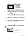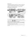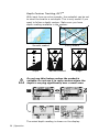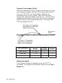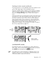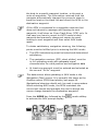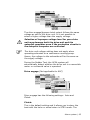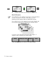
1
Operator manual
Simrad AP24
Autopilot
English
www.simrad-yachting.com
Sw.1.3
A brand by Navico - Leader in Marine Electronics
Operator manual
Simrad AP24
Autopilot
English
Sw.1.3
Document no: 20222535
Revision:
C
Date:
January 2010
The original language for this document is English. In the
event of any discrepancy between translated versions
and the English version of this document, the English
document will be the official version.
To the best of our knowledge, the content in this
publication was correct at the time of printing.
As we are continuously improving our products we retain
the right to make changes to the product and the
documentation at any time. Updated manuals are
available from our website www.simrad-yachting.com,
and are free to download.
© Copyright 2010 by Navico Holding AS.
About this manual
Rev. A
06.11.07
First issue
Rev. B
25.03.08
Rev. C
06.01.10
Updated according to autopilot
software 1.2.
Updated according to autopilot
software 1.3.
This manual is intended as a reference guide for
operating and maintaining the Simrad AP24 autopilot.
An autopilot is a complex control system so please take
time to read this manual to get a thorough understanding
of the operation, the system components and their
relationship to a complete AP24 autopilot system.
In this manual, names of menu commands, dialog box
text and keys are written in boldface (e.g. Main menu,
Setup command, Left key).
Important text that requires special attention from the
reader is emphasized as follows:
Used to draw the reader’s attention to a comment or
some important information.
Used when it is necessary to warn personnel that a
risk of damage to the equipment or hazard exists if
care is not exercised.
2 | AP24 Manual
Contents
1 Operation.................................................... 5
1.1 Overview ................................................5
1.2 ON/OFF ..................................................8
1.3 Backlighting ............................................9
1.4 Standby mode ....................................... 10
1.5 Automatic steering ................................. 12
1.6 NoDrift mode......................................... 29
1.7 Navigating with the AP24 ........................ 30
1.8 Wind vane steering (sailboats) ................. 34
1.9 Wind steering and navigation (sailboats) ... 37
1.10 Data pages.......................................... 40
1.11 Multiple station system ......................... 41
2 Main menu ................................................ 43
2.1 Data pages setup ................................... 44
2.2 Trip log................................................. 46
2.3 User setup menu.................................... 46
2.4 Remote lock .......................................... 57
3 Setup at installation.................................. 59
3.1 First time turn on ................................... 59
3.2 Installation Menu ................................... 60
3.3 Service Information................................ 90
4 Alarm system............................................ 93
4.1 Alarm indication..................................... 93
AP24 Manual | 3
4.2 Acknowledging an alarm ......................... 94
4.3 Viewing active alarms ............................. 94
4.4 Alarm codes .......................................... 94
5 Troubleshooting........................................ 97
5.1 SimNet status........................................ 97
5.2 System data.......................................... 97
5.3 Resets .................................................. 98
5.4 Alarms ................................................. 99
6 Maintenance ........................................... 103
6.1 General .............................................. 103
6.2 Control unit ......................................... 103
6.3 Autopilot computer............................... 103
6.4 Rudder feedback .................................. 103
6.5 Compass............................................. 104
6.6 Drive unit ........................................... 104
6.7 Exchange of software program ............... 104
7 Optional equipment ................................ 105
7.1 R3000X Remote Control (NFU) ............... 105
7.2 S35 Steering Lever (NFU)...................... 106
7.3 JS10 Joystick (NFU).............................. 106
7.4 AP24 with MSD50 Stern Drive unit.......... 106
8 Glossary.................................................. 109
9 Index ...................................................... 113
4 | AP24 Manual
1 Operation
An autopilot is a very useful navigational aid, but
DOES NOT under any circumstances replace a
human navigator
Do not use automatic steering when:
•
In heavy traffic areas or in narrow waters
•
In poor visibility or extreme sea conditions
•
When in areas where use of autopilot is prohibited by
law
When using an autopilot:
•
Do not leave the helm unattended
•
Do not place any magnetic material or equipment near
heading sensor used in the autopilot system
•
Verify at regular intervals course and position of
vessel
•
Always switch to Standby mode and reduce speed in
due time to avoid hazardous situations
1.1 Overview
Figure 1-1 AP24 Front Panel
Operation | 5
Key
PWR
STBY
Description
Power ON-OFF / Light key
Standby key
Engage Standby mode
AUTO
Auto key
Engage Auto mode
MODE
Mode key
Activate mode (soft) keys
Action according to the softkey symbol
TURN
Turn key
Enter turn sub-menu
Tack or gybe in Wind mode
Action according to the softkey symbol
MENU
Menu/Enter key
Enter Main menu
Enter value, Confirm, OK
Left 1 key
1
Back, Left, Cancel, Exit
Long press: Return to Main page (operation level 1)
Adjust the commanded course or wind angle 1 degree
Enable port power steering
Right 1 key
1
Next, Right
Adjust the commanded course or wind angle 1 degree
Enable starboard power steering
10
Left 10 key
Adjust the commanded course or wind angle 10 degrees
Enable port power steering
Action according to the softkey symbol
10
Right 10 key
Adjust the commanded course or wind angle 10 degrees
Enable starboard power steering
Action according to the softkey symbol
6 | Operation
Up key
Up in menu or list box, Increase
Down key
Down in menu or list box, Decrease
Softkeys
When the basic operation of the
keys is changed, softkey symbols
will be displayed right above the
keys to indicate the alternate
function.
The following softkey symbols are used:
Symbol
Action
Symbol
Action
Symbol
Action
Ok
Increase
Shallow to
stbd
Cancel
Decrease
Shallow to
port
Back
Night
backlighting
Installation
Next
Day
backlighting
Select
NoDrift mode
Up
Increase
Present
information
Select NAV
mode
Down
Decrease
Reset trip
log
Select WIND
mode
Symbols
Inactive unit, disabled data page
Alarm reminder
Locked
Operation | 7
Operational modes
The AP24 system is capable of the following primary
steering modes: STBY (power steering), AUTO, NoDrift,
NAV, WIND and WINDNAV.
STBY and AUTO modes have dedicated keys while the
other modes are available via softkeys under the MODE
key.
The WINDNAV mode can only be entered in WIND mode.
Each mode provides you with a multifunction mode
display.
User adjustable settings are found in the AP24 Main
menu (page 43).
Alarms
Alarms are presented in plain text to alert you of system
and external data failure conditions. Alarms are both
audible and visual. The alarm listing is on page 99.
Transfer of command
In a multistation system the command can easily be
transferred from one unit to another by pressing any
mode key. However, you can make a direct course
change on an inactive unit. Pressing Port/Stbd key or
turning the course knob on an inactive unit makes it
active.
AP24 units not in control will display the
icon.
Advanced operation
Refer to the Setup item in the Main menu page 46 for
information.
1.2 ON/OFF
At first time turn on see page 59.
8 | Operation
A single press on the PWR key turns the autopilot
system on and presents the start-up pages.
•
Product name
•
Serial number
•
Software version
•
Release date
Software version and release date are examples only.
After approximately 5 seconds, the system is operative
and the unit that was turned on will show the Standby
mode display. Other units in a multistation system will
display . Control is transferred to any single unit by
pressing its STBY key.
A long press on the PWR key activates the power down
dialog box and the autopilot goes to STBY mode before it
is turned off after 3 seconds.
In an emergency it is possible, on a multistation system,
to turn OFF the system at any control unit by pressing
the PWR key.
Please note that even if the autopilot is turned off, a
small amount of current is drawn from the batteries
unless you throw the circuit breaker.
1.3 Backlighting
The display backlighting may be adjusted at any time.
PWR
1
Press the PWR key
-
2
The Light level overlay window
will be displayed on top of the
current view
Press one of the keys, as described below, to
change the display backlighting:
Operation | 9
PWR
a
The PWR key to increase the light level by one
step
b
The Up/Down softkeys to increase/decrease
the light level by one step
c
The Day/Night softkeys to toggle between day
and night profiles
If no adjustment is performed within 3 seconds, the Light
level overlay window will close.
For contrast and day/night settings, refer to page 52.
1.4 Standby mode
STBY mode is the mode that is used when steering the
boat at the helm.
Display information:
•
Standby mode
•
Current heading 346°M
•
Compass source: RC42
•
Rudder angle 01° to starboard
See page 70 about VRF.
Power steering (NFU)
In Standby mode, press any of the PORT or STBD keys.
The Non-Follow-Up (NFU) display is presented and the
rudder will move as long as the key is pressed.
10
10
or
or
1
1
Activates PORT
rudder command
Activates STBD
rudder command
When a NFU steering lever or remote control is operated,
other control units show
10 | Operation
(inactive). Refer to section 7
for operation of NFU steering levers or remote controls.
Alternative displays in Standby mode
Alternating rudder angle bargraph
If your autopilot is driving a Simrad
MSD50 Stern Drive, the rudder
angle display will after turn-on
alternate between 10 degrees port
and starboard to indicate that the
(rudder) zero point need be set.
Refer to page 107 to set the zero point.
No rudder angle bargraph
When the autopilot is operating on
Virtual Rudder Feedback (VRF), the
rudder angle bargraph is empty in
Standby mode.
No mode indication
When the autopilot is configured for
Electronic Vessel Control (EVC), you
can take manual control of the
steering by means of the helm
irrespective of the autopilot mode.
The autopilot will go to Standby
mode. The “S” in the display is
replaced by a dash to indicate that
steering is from the helm. Ref. page
109.
Operation | 11
1.5 Automatic steering
AUTO (Compass) mode
When the AUTO key is pressed, the AP24 automatically
selects the current boat heading as the set course and
maintains the rudder angle. This gives a bumpless
transfer at the mode change.
• Automatic steering mode
• Set course: 340 degrees
• Compass reading: 340°M
• Heading source: RC42
• Rudder angle: 01° to
starboard
• Speed: 5.6 kn (from log)
• Steering parameter set: LO-A
(Low automatic)
The AP24 will keep the boat on the set course until a new
mode is selected or a new course is set with these keys.
1
10
10
1
Port course
adjust,
1°/press
Port course
change,
10°/press
Stbd. course
change
10°/press
Stbd. course
adjust
1°/press
Once the course is changed to a new set course, the boat
will automatically turn to the new heading and maintain
the new course.
Heading capture
When in AUTO or NoDrift mode (page 29) heading
capture allows you to automatically cancel the turn you
are in by an instant press on the AUTO key or the
NoDrift softkey. The autopilot will cancel the turn to
continue on the heading read from the compass the very
moment you pressed the AUTO key or the NoDrift
softkey. This is a useful feature if you are not sure of the
exact turn you have to make to hit e.g. an inlet or a
dock.
12 | Operation
STBY
•
Automatic steering mode
•
New “captured” heading: 305°
•
Compass reading: 311° M
(magnetic) or T (true)
Regain manual steering by pressing the STBY key.
Control of steering performance
When operating in an automatic mode the AP24 utilizes
two different sets of steering parameters (HI/LO). The
parameters control the response of the boat at different
speeds or wind directions. The two parameter sets can be
automatically or manually selected, and each set can be
manually adjusted (response adjust).
The speed at which the autopilot automatically changes
from LO to HI parameters (or opposite) is determined by
the "Transition HI-LO" set in the Installation/
Commissioning/Seatrial menu, page 78. See diagram
below.
At no speed input the autopilot defaults to LO steering
parameters when engaging an automatic mode from
STBY. This is a safety feature to prevent oversteering.
Speed
26
24
22
20
18
16
14
12
10
8
6
4
2
0
LO
H
nse
spo
I re
rs
ete
am
par
se
pon
res
rs
ete
am
par
Transition to LO parameters
with increasing speed: 10 Knots
Transition Speed set to 9 Knots
Transition to HI parameters
with decreasing speed: 8 Knots
Operation | 13
Display legend
HI-A
High response parameters set automatically
LO-A
Low response parameters set automatically
HI-M
High response parameters set manually
LO-M
Low response parameter set manually
Power boats
On power boats the automatic selection of HI or LO is
determined solely by the speed of the boat as shown in
the diagram above.
Sailboats
When sailing in WIND mode, the parameter set is
determined by the speed of the boat and the direction of
the wind as per below.
So if you loose too much speed e.g. when tacking, the
parameters will change to HI to gain sufficient rudder
response. This should be observed when setting the
transition speed on sailboats. See also Wind response on
page 15.
Response adjust
The Autotune function in the AP24 is so refined that the
majority of boats will need no further adjustments of the
steering parameters. On some boats, however, or at
particular sea conditions a fine tuning of the steering
parameters may improve the performance of the
autopilot.
The Response control allows you to make this fine tuning
for each of the two (HI/LO) parameter sets. The response
can be set to nine levels. Level 4 is default with
14 | Operation
parameter values as set by the Autotune function. If no
Autotune is made (not recommended) the level 4 values
are the factory default values.
A low response level reduces the rudder activity and
provides a more “loose” steering.
A high response level increases the rudder activity and
provides a more “tight” steering.
A too high response level will make the boat start S-ing.
When you access the RESPONSE page the highlighted
Response parameter is the one that is active.
1
MENU
Adjustment of HI and LO values can be performed even
with the boat out of the water.
Range
Change per step
Default
1-9
1
4
Wind response (sailboats)
Verify that the difference between Course To Steer (CTS)
and the actual heading is at an acceptable minimum.
If the difference between the set wind angle and the
actual wind angle is too big, increase the Wind response
to reduce the difference.
Operation | 15
If the actual wind angle is S-ing around the set wind
angle, or the rudder activity is too high, the ‘Wind
response’ should be reduced.
1
MENU
Range
Change per step
Default
1-9
1
4
Selection of HI/LO parameters
1
1
MENU
The “Manual select” item has three alternatives:
Auto – HI – LO.
16 | Operation
•
Auto is automatically set by speed input
•
HI or LO must be set manually when there is no
speed input
The sub-headline in the display shows the
active parameter set and how it is selected.
Pattern steering (power boats)
The autopilot offers a number of different pattern
steering features when in AUTO mode. There is a one
minute time-out between selecting a turn pattern and
starting the turn. During the time-out period the autopilot
will maintain the set course.
When steering in a turn pattern you may at any time
adjust the variables by pressing the
key.
To exit a turn pattern simply press the AUTO key.
U-Turn
U-Turn changes the current set course to be 180 degrees
in the opposite direction.
This feature is very useful in a man overboard situation
and whenever you want to steer back on a reciprocal
heading.
TURN
Press either the
or
softkey to select the direction
to make the U-Turn and start the turn.
Boat makes starboard U-turn
C-turn
The autopilot provides a continuous turn feature when in
AUTO mode. This may be used for circling fish or a
particular object on the seabed.
Operation | 17
C-turn makes the boat turn in a circle with a constant
rate of turn. The user decides whether the C-turn should
be made to port or to starboard.
To enter C-turn mode:
TURN
or
softkey to select the direction in which
Press the
to make the C-turn and start.
The turn rate (ROT) can be adjusted before the turn is
initiated and during the turn. Increasing the turn rate
yields to a smaller circle and vice versa.
1
18 | Operation
Turn
parameter
Range
Change per
step
Default
Units
Rate of turn
10 - 600
5
90
°/min
Spiral-turn
The spiral-turn feature may also be used for circling fish
or when searching a particular object on the seabed.
Spiral-turn makes the boat turn in a spiral with a
decreasing or increasing radius.
To enter Spiral-turn mode:
TURN
The “initial” radius can be set before the turn is started.
or
softkey to select the direction in
Press either the
which to make the spiral-turn and start.
During the turn the “change in radius” can be adjusted
and the number of feet or meter is how much the radius
is changed for each circle turned.
If the “change radius” is set to zero, the boat will turn in
a circle.
Operation | 19
1
Negative values indicate decreasing radius while positive
values indicate increasing radius.
Increasing radius
Turn parameter
Initial radius
Change of radius
per turn
Decreasing radius
Range
Change
per step
Default
33 ft - 3281 ft
10
656 ft
10 m - 1000 m
10
200 m
-164 ft - +164 ft
5
66 ft
-50 m - +50 m
2
20 m
The unit for radius is the same as the unit set for depth
(feet or meter).
20 | Operation
Zigzag-turns
To enter zigzag-turn mode:
TURN
The course change can be set before the turn is initiated
(2-70°).
Press either the
or
softkey to select the direction in
which to make the first course change and start.
While sailing in a zigzag pattern you can alter the course
change, leg distance, and the main course. An arrow
shows the direction of the next course change.
1
Operation | 21
Initial course change 20°
Main course
Course change 40°
Leg distance
Turn parameter
Range
Change
per step
Default
Course change
4° - 140°
4
28°
82 ft - 9843 ft
50
1641 ft
25 m - 3000 m
25
500 m
Leg distance
The unit for leg distance is the same as the unit set for
depth (feet or meter).
Square-turn
The square-turn feature in AUTO mode can also be made
as rectangle or any pattern where the next turn is 90°.
To enter Square-turn mode:
TURN
Leg distance
or
softkey to
Press either the
select the direction in which to make
the first course change and start.
22 | Operation
You can at any time change the main course.
You can also at any time change the distance of the leg
until the boat makes a new 90° turn.
1
Turn parameter
Leg distance
Range
Change
per step
Default
82 ft - 9843 ft
50
1641 ft
25 m – 3000 m
25
500 m
The unit for leg distance is the same as the unit set for
depth (feet or meter).
Operation | 23
Lazy S-turn
To enter Lazy S-turn mode:
TURN
The course change can be adjusted before the turn is
initiated (2-80°).
Press either the
or
softkey to select the direction in
which to make the first course change and start.
While in a Lazy S pattern you can alter the course change
magnitude, turn radius and the main (average) course.
An arrow shows the direction of the turn.
24 | Operation
Adjust course change and radius as follows:
1
Initial course change
Main course
Course change
Higher radius
Main course
Lower radius
Turn parameter
Course change
Radius
Range
Change
per step
Default
4° - 160°
4
28°
16 ft - 1641 ft
10
656 ft
5 m – 500 m
5
200 m
The unit for radius is the same as the unit set for depth
(feet or meter).
Operation | 25
Depth Contour Tracking, DCTTM
With input from an echo sounder, the autopilot can be set
to steer the boat to a set depth. This is very useful if you
want to follow a depth contour. Make sure you have
depth reading available in the system.
Smooth seabed
Slope
Rocky waters
Narrow channel
Ridge
Do not use this feature unless the seabed is
suitable. Do not use it in rocky waters where the
depth is varying significantly over a small area.
TURN
The actual depth reading is shown on the display.
26 | Operation
Steer the boat to the depth you want to track and in the
direction of the depth contour (main course). When the
wanted depth is shown in the display, activate the depth
contour steering with the
or
softkey (any of the
key when it is shallow to port or the
two). Use the
key when it is shallow to starboard.
Main course
This should be the main (average) direction of the depth
contour you want to follow. If the contour line is making
a big change in direction, you should manually adjust the
set course to the new direction. This will result in a
quicker response from the autopilot. If the course is not
adjusted, the autopilot will need more time to turn and
steer the boat back to the reference depth.
The sub screen has the following adjustments:
Depth gain
The autopilot is tracking the depth by computing an xtrack error when the boat is off the reference depth. This
error automatically adjusts the set course to bring the
boat back on track.
Use the gain control to have a firm or smooth response to
the variation in depth.
1
Operation | 27
Contour Cross Angle (CCA)
With this parameter you can make the boat lazy s across
your reference depth. With the CCA set to zero there is
no S-ing. The CCA is an angle that is added to or
subtracted from the set course. Each time the boat
crosses the reference depth, the sign (+/-) of the CCA is
changed and makes the boat turn to cross the reference
depth contour in the opposite direction. The larger the
CCA the bigger the turn.
CCA set to 15 degrees.
Approaching reference
depth from port
Reference
depth
CCA set to 15 degrees.
Approaching reference
depth from starboard
Turn parameter
Range
Change
per step
Default
Main course
0° - 359°
1
–
Depth gain
5 - 95
5
5
Contour Cross Angle
0 - 50
1
0
Reference depth
The reference depth is captured when the DCTTM is
activated. To change the reference simply use the Up or
Down key.
28 | Operation
Tacking in Auto mode (sailboat)
The tack function is only available when the system is set
up for SAIL boat type in the installation setup.
Tacking in AUTO mode is different from tacking in WIND
mode. In AUTO mode the tack angle is fixed and can be
set in the Setup/Sailing menu. Default tack angle is
100°.
Tacking should only be performed into the wind and must
be tried out in calm sea conditions with light wind to find
out how it works on your boat. Due to a wide range of
boat characteristics (from cruising to racing boats) the
performance of the tack function may vary from boat to
boat. Except for the fixed course change and the
difference in displays, the procedure is similar to that of
the U-Turn described on page 16.
TURN
For
sailboat
only
Boat makes
starboard tack
1.6 NoDrift mode
The NoDrift mode is an alternative to route steering in
NAV mode, and is automatically entered when you press
the MODE key followed by the
softkey.
The data source when operating in NoDrift mode is the
Position (Pos) source. To operate in NoDrift mode your
GPS/chart plotter must be turned on.
Operation | 29
MODE
Unlike when in Auto mode the autopilot will steer the
course unaffected by wind and current when the NoDrift
mode is engaged.
The course to steer to (bearing line) can be changed the
same way as when changing course in Auto mode.
•
Compass heading: 345° M
•
Rudder Angle: 01 to starboard
•
Speed: 6.8 kn from the log
•
Steering parameter: HI-A
Dodging (Resume previous bearing line)
The AP24 has no specific dodge key. When in NoDrift
mode, simply press STBY and power steer or use the
helm to pass any obstacle.
If you return to NoDrift mode within 60 seconds the
following display is shown, offering two alternatives:
Go back to NoDrift mode
on previous set bearing
line
MODE
+
Go to NoDrift mode with
current heading as set
bearing line
If none of the two softkeys are pressed within 5 seconds,
the dialog box will disappear and the autopilot will go to
NoDrift mode with current heading as set bearing line.
If your dodging maneuver takes more than 60 seconds,
the autopilot will remain in Standby mode.
1.7 Navigating with the AP24
The AP24 has the capability to use steering information
from an external navigator (GPS, chart plotter) to direct
30 | Operation
the boat to a specific waypoint location, or through a
route of waypoints. The information received from the
navigator automatically changes the course to steer to
keep the boat on the track line and direct the AP24 to the
destination waypoint.
If the AP24 is connected to a navigation receiver that
does not transmit a message with bearing to next
waypoint, it will steer on Cross Track Error (XTE) only. In
that case you have to revert to AUTO mode at each
waypoint and manually change set course to equal
bearing to next waypoint and then select NAV mode
again.
To obtain satisfactory navigation steering, the following
points must be fulfilled prior to entering the NAV mode:
•
The AP24 autosteering must be tested and determined
satisfactory
•
The navigation receiver (GPS, chart plotter) must be
in full operating mode with adequate signal
characteristics for valid position and navigation data
•
At least one waypoint must be entered and selected as
the current “Go to” waypoint
The data source when operating in NAV mode is the
Navigation (Nav) source. It is normally the same as the
Position source (GPS/chart plotter) see page 49.
Navigational steering should only be used in open waters.
When selecting NAV mode, the AP24 maintains the
current set course and prompts the user to accept the
course change towards the destination waypoint.
Press the MODE key followed by the
to activate the NAV prompt display.
mode softkey
MODE
Operation | 31
The prompt display shows the name of the next waypoint
(WP), the bearing of the track line (BWW) from the
previous waypoint to the destination waypoint, the
required course change (CHG) and the direction in which
the boat will turn.
If only one waypoint has been entered the bearing will be
from the present position to the destination waypoint.
•
NAV mode
•
Course to steer (CTS): 014 is
set internally by the autopilot
to steer the boat onto the track
line and maintain the bearing
•
Cross Track Error (XTE): 0.014 nm
•
Boat symbol illustrating whether the boat is to port or
starboard of planned track
•
Compass heading: 345° M
•
Next waypoint: Eigeroy
•
Bearing to next waypoint (BTW): 014°M
•
Distance to next waypoint (DTW): 124.7 nm
•
Steering parameter: HI-A
For Cross Track Error, the number of decimals shown
depends on the output from the GPS/chart plotter. Three
decimals give a more accurate track keeping.
When operating the AP24 in NAV mode to steer through a
route of waypoints, the AP24 will steer to the nearest
waypoint in the direction of the route after you accept the
NAV mode prompt. When you arrive at the waypoint, the
AP24 will output an audible warning, display an alert
screen with the new course information, and
automatically change course onto the new leg.
If the required course change is more than the NAV
change limit (default 10°), you have to verify that the
upcoming course change is acceptable. This is a safety
feature. See page 69 on how to change the ‘NAV change
limit’.
32 | Operation
Press the
softkey to
verify course change
larger than 10°.
Alert screen
STBY
If no verification is made,
the AP24 will continue on
the current set course in
AUTO mode.
Regain manual steering by pressing the STBY key.
Setting the waypoint arrival circle
For route navigation it is recommended to use automatic
waypoint shift at a set waypoint arrival circle.
The arrival circle should be adjusted according to boat
speed. The higher the speed, the wider the circle. The
intention is to make the autopilot start the heading
change in due time to make a smooth turn onto the next
leg.
The figure below may be used to select the appropriate
waypoint circle on the GPS/chart plotter.
Operation | 33
Example: With the speed of 20 knots you should use a
waypoint circle with radius 0.09 nm.
The distance between any waypoints in a route must not
be smaller than the radius of the waypoint arrival circle
when using automatic waypoint shift.
Selecting a different navigation source
If you have more than one navigator connected to the
AP24, you will be able to choose any for navigation. Refer
to the ‘Sources’ item in the Setup menu for details on
how to select a different navigator (page 50).
1.8 Wind vane steering (sailboats)
The WIND mode is only available if the system has been
set up for SAIL-boat in the Installation Menu.
Prior to entering WIND mode the AP24 system should be
operating in AUTO, with valid input from the wind
transducer.
Enter the WIND mode by pressing the MODE key
followed by the
MODE
34 | Operation
softkey.
The wind display presents the following information:
•
Wind (vane) mode
•
Set wind angle: 010 degrees from starboard
•
Measured wind angle: 009°A (apparent) or T (true)
•
Course to steer (to maintain set wind angle): 345°
•
Heading: 344° M (magnetic) or T (true)
•
Rudder angle: 00°
•
Speed from log: 6.8 kn
•
Parameter: HI-A (High value, automatic set)
The set course to steer (CTS) and set wind angle are
entered from the compass heading and the wind
transducer at the moment the WIND mode is selected.
From that point the autopilot will change the course to
maintain the wind angle as the wind direction may
change.
If the cumulative shift of the wind direction exceeds a set
limit a WIND SHIFT alarm will sound.
Adjustments to the set wind angle is as per below.
STBY
1
10
10
1
Steer port,
1°/push
Steer port,
10°/push
Steer stbd.,
10°/push
Steer stbd.,
1°/push
Regain manual steering by pressing the STBY key.
Tacking in Wind mode
Tacking in WIND mode as compared to AUTO mode can
be performed when sailing with apparent or true wind as
the reference; the true wind angle should be less than 90
degrees.
The tacking operation will immediately mirror the set
wind angle to the opposite side of the bow. A tack
window will appear on the display. The rate of turn during
Operation | 35
the tack will be given by the ‘Tack time’ parameter set in
the Setup/Sailing menu (page 55). The tack time is also
controlled by the speed of the boat to prevent loss of
speed during a tack.
A quick press on the TURN key will activate the tack
function and the boat will start turning to the opposite
wind angle.
A new press on the TURN key after the Tack window
appears, will interrupt the tack operation and the boat will
return to the previous set wind angle.
TURN
Gybing
Gybing is possible when the true wind angle is larger
than 120°.
TURN
The time to make a gybe is determined by the speed of
the boat to make it as quick as possible within control.
36 | Operation
Tack and gybe prevent
When beating and running, using the autopilot is most
critical.
If the sails are unbalanced when beating, yaw forces from
the sails can drive the boat into the wind. If the boat is
driven beyond the set minimum wind angle (see page
84), the thrust from the sails will suddenly disappear and
reduces the boat speed. Hence the boat will be more
difficult to steer because the rudder will become less
effective.
The tack prevent function in WIND mode has been
implemented to avoid such situations. It will react
immediately when the apparent wind angle becomes 5°
less than the set minimum wind angle, and more rudder
will be commanded.
When running, it is difficult to steer the boat with waves
coming sideways or from behind. The waves may yaw the
boat into an unwanted gybe; this can be hazardous for
both the crew and the mast.
The gybe prevent function will be activated when the
actual apparent wind angle becomes greater than 175° or
gets opposite to the set wind angle. More rudder will be
commanded to prevent an unwanted gybe.
The tack and gybe prevent functions are not a
guarantee against getting into a hazardous
situation. If the effect of the rudder and/or drive
unit is not adequate, it may happen. Pay particular
attention in such situations.
1.9 Wind steering and navigation
(sailboats)
The autopilot can also steer the boat given both wind
data and track data from a GPS/chart plotter. In this
mode called WINDNAV mode the automatic steering is
based on a set of criteria (see bullets next page). Wind
steering and navigation is activated by pressing the
MODE key when in Wind mode [1] followed by the
mode softkey. The initial course change (CHG) needed to
navigate towards the active waypoint, is calculated by the
Operation | 37
autopilot. The autopilot will utilize the current wind
direction in these calculations and the change of course is
accepted by pressing the
softkey [2].
Operating in WINDNAV mode
Refer to Figure 1-2 which shows a scenario with a sailboat
that enters WindNAV mode to sail the most efficient way to
waypoint WP1.
1. The autopilot is still in Wind mode approaching mark
2 and waypoint WP1 has been entered on the chart
plotter.
2. The WindNAV mode is entered and the autopilot
prompts confirmation for a course change of 71
degrees to starboard.
3. The boat is now on the leg to mark 4 where a
starboard tack is required to avoid running on
ground. The distance to tack DTT is displayed and so
is VMG to wind. Furthermore the autopilot displays
course to steer and heading.
4. The tack has been initiated on the autopilot and the
tack display is presented.
5. The autopilot now presents you with information
about the new leg and the next tack.
6. You are about to cross the layline and the autopilot
“recommends” a new tack to Port.
7. The new tack is performed.
8. You are on the last leg directly to the waypoint. The
autopilot is now keeping the boat on track (XTE) and
displays bearing and distance to the waypoint.
38 | Operation
Figure 1-2
Operation | 39
1.10 Data pages
A number of data pages can be displayed if the
information is available on SimNet (see page 97).
When one of the main mode pages are displayed, access
and scroll through the available data pages by pressing
the Up/Down keys.
When accessing the data pages, the last active data page
will be shown first.
If you prefer to change the number of instrument pages
to be available; access the Main menu/Data pages
setup.
When displaying data pages the left hand side of the
screen will show the following information depending on
mode:
Standby
mode
Auto mode
Nav/NoDrift mode
Wind mode
WindNAV mode
Heading
Set course
Course to steer
Set wind angle
Set wind angle
Heading
Heading source
Cross Track Error
(XTE)
Actual apparent
wind angle
Actual apparent
wind angle
HI parameters,
set automatically
HI parameters,
set automatically
HI parameters,
set automatically
HI parameters, set
automatically
Heading
source
40 | Operation
Available data pages
Main mode screen
1.11 Multiple station system
In normal operation control is accessible from every
control unit connected to the AP24 system. One control
unit is "active" and provides the user with access to all
functions. All remaining control
units are "inactive" and have no
effect on course changes. A single
press on any of the mode keys on
an "inactive" control unit will allow
transfer of command and make it
Inactive unit
"active".
Operation | 41
Blank page
42 | Operation
2 Main menu
In the Main menu you will find items for operation, setup
and installation of the autopilot. The Service menu item
presents you with various system information and access
to the Demo mode.
Main menu | 43
The Main menu is activated by a press on the MENU key.
The Main menu items give further access to sub menus
and parameter settings.
Parameter settings are usually presented to the right, but
may also be listed in an overlay window.
Unit settings presented in
the window’s right column
Language settings presented
in an overlay window.
The keys are used as follows to navigate in the menu
system:
KEY
MENU
1
1
SINGLE PRESS
PRESS AND HOLD
Confirm a selection/parameter
setting
Go to next menu level/
parameter settings
Go to previous menu level/
parameter listing
Return to active mode
display
Go to previous/next menu item,
increase/decrease parameter
value
2.1 Data pages setup
All available data pages are enabled as default. See page
41. If you prefer to have less data pages available, pages
may be disabled.
44 | Main menu
Disabling pages
1
Continue to select pages and repeat the procedure if
more pages are to be disabled.
1
Press and hold the Left 1 key to leave the menu and
return to last active page.
Enabling pages
A disabled page is only visible when
using the Enable/disable command.
A disabled page is indicated with a
crossed rectangle.
1
Continue to select pages and repeat the procedure if
more pages are to be enabled.
1
Press and hold the Left 1 key to leave the menu and
return to last active page.
Main menu | 45
Enabling all pages
To restore all disabled data pages, select Restore data
pages:
1
2.2 Trip log
The trip log display shows:
a. total accumulated distance
since the instrument was
installed or factory reset
b. distance since the trip log
was started/reset
Resetting the trip log
The trip log is reset to zero by pressing the Reset soft
key.
2.3 User setup menu
The User setup menu contains items that the user may
want to use on a less regular basis.
The following items are described:
46 | Main menu
-
Changing the damping factors
-
Alarm setup
-
Automatic and manual source selection
-
Changing the display settings
-
Language selection
-
Setting the units of measure
-
Adjusting the sea state filter
-
Changing the sailing parameters
The section assumes that the user is familiar with how to
use the keys and how to maneuver in the menus. If not,
refer to Main menu, page 43 onwards.
1
Damping
The damping factor indicates how fast the display will
respond to changes.
The higher the damping factor the more stable display
reading on the instrument.
Damping of the apparent wind angle is made by the
Advanced Wind Filter (AWF) in the Autopilot Computer.
Increasing the ‘Wind damping’, will make the AWF output
depend more on heading and boat speed. Decreasing the
‘Wind damping’, will make the AWF depend more on the
“raw” apparent wind angle data.
The speed input to the AWF is Speed Over Ground (SOG).
If SOG is not available, the AWF will use speed through
water. If none of these are available, the AWF will use a
boat speed that is 1.5 times the Transition Speed.
Main menu | 47
Setting
Range
Change per step
Default
Boat speed
4
Heading
1
0-9
Apparent wind
1
4
Wind shift
4
Depth
1
Alarms
The AP24 may be set up to sound an alarm if vessel or
environmental parameters exceeds preferred values.
The alarm monitoring is disabled by setting the value to
Off.
Shallow water
The setting of the alarm is global and can be made on
any Simrad unit that has this function implemented.
Range
Off – 320 ft
Change per step
1.6 – 5:
0.1 ft
5 – 10:
0.5 ft
10 – 50:
1 ft
50 – 100:
5 ft
100 – 320: 10 ft
(Off – 100 m)
(0.5 – 5: 0.1 m)
(5 – 10:
(10 – 50:
0.5 m)
1 m)
(50 – 100: 5 m)
48 | Main menu
Default
Units
Off
ft, m
Wind shift
(Only available in Wind/WindNAV mode)
The wind shift alarm monitors the wind angle. The
reference angle is set when the alarm is turned on and
when the product is turned on. The reference wind angle
is reset to present wind angle when the commanded (set)
wind angle is changed on the autopilot and when a wind
shift alarm is acknowledged.
The wind shift reading is presented on the ‘Wind shift’
data page and shows the change of wind angle with
reference to the (geographic) wind direction.
Range
Change per step
Default
Off, 5-90°
1
20°
Alarm status
Displays a list of present alarms.
Setup data sources
A data source can be a sensor or a device connected to
SimNet providing data to other SimNet devices. Data can
be of different type such as compass data, apparent wind
data, calculated wind data, depth data, etc. A given data
type will only be provided from one device to the other
devices organized in a SimNet Source group (Ref.
Installation/ SimNet groups, page 88).
At the first time turn on of a group of SimNet
interconnected products (SimNet Source Group), data
sources are automatically selected from an internal
SimNet priority list. If a data source is connected to
SimNet after the first time turn on, this will be identified
and automatically selected if no other data source already
is selected for the given data type.
It is only required to update the SimNet source selections
if an alternative source is made available for a given data
type and this source has not been selected automatically.
Main menu | 49
The data types and their
respective data sources used in
the products are listed on the
source page in the products.
If no selection is made for a data type, ‘- - -‘ is displayed
instead of the device name or acronym.
SimNet will automatically select Position source and
Navigation source from the same GPS/chart plotter. If
you want them to be different you have to change them
manually.
Automatic source update
The Auto select function is mainly for situations where
the automatic source selection needs to be updated
because a selected data source is not supplying data or
has been physically replaced with another one. The
update secures that the existing source selections are
valid and maintained. Missing sources are either
automatically exchanged with an alternative source from
the list of available sources for the given data type or the
replacing source is selected. If a source is no longer
available for the given data type, the display will show
‘- - -‘ instead of the source acronym.
If more than one source is found for each data type, the
preferred source may be manually selected.
Manual source selection
Data sources can also be selected manually. All devices
providing data of the given type will be listed in a device
50 | Main menu
list. Highlight the data type and press the
display the list of available devices.
1
key to
Confirm selection of the highlighted device.
Exit without selecting
See information about the
selected data source.
For data types which can be calibrated, an overlay screen
displaying the data from the selected data source will
appear first (Ref. Installation/Calibration).
Enter the Calibrate and Offset
menu.
(Ref. Installation/Calibration).
Proceed to display a list of
available sources for the given
data type.
Main menu | 51
Display
The display is controlled by two user profiles that can be
individually adjusted.
The profiles are Day profile and Night profile. The
profiles can be optimized for readability under different
light conditions, and you can quickly switch between the
two using the PWR key and the
Backlighting, page 9.
softkeys. Refer to
For each profile you can:
-
Adjust light level
-
Select white or red light color
-
Invert the display
-
Adjust contrast
Setting
Range
Change per step
Default
Light level
Off – 9
1
3
Light color
White/red
-
Yes/No
-
No
0-9
1
4
Invert display
Contrast
52 | Main menu
White (Day)
Red (Night)
Language
The language is set when the autopilot is turned on for
the first time. Refer First time turn on, page 59.
It is however possible to change the language at any
time.
The following languages may be selected:
-
Deutch (German)
-
English (English)
-
Español (Spanish)
-
Français (French)
-
Italiano (Italian)
-
Nederlands (Dutch)
-
Norsk (Norwegian)
-
Svenska (Swedish)
The language names are listed alphabetically in their own
language.
Default language: English
Main menu | 53
Units of measure
Parameter
Boat speed
Options
− kn
Default
kn
− km/h
− mph
Wind speed
− kn
kn
− m/s
− mph
Distance
− nm
nm
− km
− mi
Depth
− m
ft
− ft
Heading
− °M
°M
− °T
Temperature
− °C
°F
− °F
The display unit for heading data is not solely determined
by the user. If true heading is wanted but the selected
compass is a magnetic compass, then the magnetic
variation must be available from a position- or navigation
source. The same applies if the user wants to read
magnetic heading but receives true heading from the
compass.
If magnetic variation is required but not available, the
compass decides which unit to display.
54 | Main menu
Sea state filter
The Seastate filter is used to reduce rudder activity and
autopilot sensitivity in rough weather.
OFF:
Seastate filter is disabled. This is default.
AUTO:
Reduces rudder activity and autopilot
sensitivity in rough weather by an adaptive
process. The AUTO setting is recommended
if you want to use the Seastate filter.
MANUAL:
Linked to the Response control setting in
the Main menu. It may be used to
manually find the optimum combination of
course keeping and low rudder activity in
rough but steady sea conditions.
Sailing
‘Sailing’ is only available in the menu if ‘Boat type’ is set
to ‘Sail’ in the Installation menu (see page 61).
The ‘Sailing’ screen can also be reached from the Wind
mode main screen by pressing the MENU key followed by
the MODE key within 2 seconds.
Main menu | 55
Tack time
When performing a tack in WIND mode, the rate of turn
(tack time) can be adjusted. This will give single-handed
sailors time to handle the boat and the sails during a
tack.
A turn performed without shifting wind side, will also be
made at a controlled turn rate.
Range
Change per step
Default
Units
2 - 50
1
12
second
Tack angle AUTO
In AUTO mode the set tack angle replaces a similar
change of the set course using the starboard and port
keys.
Range
Change per step
Default
Units
50 - 150
1
100
°
Wind function
With ‘Wind function’ set to ‘Auto’, the autopilot will
automatically select between apparent and true wind
steering. ‘Auto’ is default and recommended for cruising.
When the boat is running, it will also be surfing on the
waves. This may lead to significant changes in boat
speed, hence changes in apparent wind angle. True wind
steering is therefore used when running, while steering to
apparent wind is used when beating or reaching.
‘Apparent’ wind steering is preferred when you want to
achieve maximum boat speed. The autopilot tries to
maintain a constant apparent wind angle to get
maximum thrust from a given trim of the sails.
When sailing in closed waters, the apparent wind angle
may change temporarily due to wind gusts. It may then
be preferred to sail to the true wind; select ‘True’.
56 | Main menu
Range
Default
Auto – Apparent - True
Auto
VMG optimizing
Optimizing the VMG to wind will be active for 5–10
minutes after a new wind angle has been set and only
when beating.
‘VMG’ will be displayed in the upper left corner above the
mode index when the VMG optimizing feature is active.
Range
Default
Off - On
Off
Layline steering
Layline steering is useful when navigating. Cross Track
Error (XTE) from the navigator will keep the boat on the
track line. If the XTE from the navigator exceeds 0.15
nm, the autopilot will calculate the layline and track
towards the waypoint.
‘XTE’ will be displayed in the upper left corner above the
mode index when layline steering is active (page 38).
Range
Default
On - Off
On
2.4 Remote lock
The "Remote lock" function is a safety feature included in
the AP24 system. It will disable all other control units.
When the "Remote lock" function is in use, no transfer of
command can take place; only the active control unit
stays in command.
The "Remote lock" function is enabled as follows:
1
Main menu | 57
On the active control unit a
the mode index.
icon will alternate with
The "locked" control units in the system will show:
The Lock function is disengaged by one of the following
actions:
•
The active control unit unlocks the other ones and
makes them inactive:
1
•
58 | Main menu
The system is switched OFF by any control unit (press
PWR key for 2-3 seconds)
3 Setup at installation
3.1 First time turn on
Before attempting to turn on the AP24 and perform an
Installation Setup, the hardware installation and electrical
connections must be completed in accordance with the
installation instructions.
When the AP24 is powered on for the first time, the
instrument will run through an automatic start-up
sequence presenting:
-
Product name, software version, release date
-
Language selection
-
Automatic data source selection
The display will show which items
of the installation setup that needs
to be done and those already done.
Press the
softkey to continue
with the installation setup according
to the next chapters.
Alarm system | 59
3.2 Installation Menu
The installation settings must be performed as part of the
commissioning of the AP24 system. Failure to do so
correctly may prohibit the AP24 from functioning properly!
The Installation menu can only be accessed in STBY
mode.
1
The Installation settings are grouped into the following
functional categories:
•
Commissioning:
Dockside and Seatrial setup
•
Automatic steering: Permits viewing and changing of
basic steering parameters (See
also response control on page 14)
•
Calibration:
Calibration of sensors (also partly
part of Commissioning)
•
Boat type:
Select boat type (also part of
commissioning)
•
Rudder drive:
Rudder drive setup (also part of
commissioning)
•
SimNet config:
SimNet group setup
Each group is designed to focus on specific functions and
enable quick access when changes need to be made.
Some important points regarding the installation settings:
•
When the AP24 is delivered from factory AND ANY
TIME AFTER AN AUTOPILOT RESET HAS BEEN
PERFORMED, the installation settings are all reset to
factory preset (default) values. The automatic
interface prompt will appear (see page 59) and a
complete setup has to be made.
•
The Seatrial settings are dependent on successful
completion of the Dockside settings.
60 | Alarm system
Commissioning
1
Dockside settings
1
If the autopilot has no rudder feedback unit installed refer
to Virtual Rudder Feedback on page 70-72.
The following menu items are accessible and can be set
up in the Dockside menu:
-
Boat type
-
Rudder feedback
-
Virtual feedback
-
Drive voltage
-
Drive engage
-
Rudder test
-
Depth calibration
-
Minimum wind angle
-
Nav change limit
Not applicable
for EVC!
(ref. page 109)
Boat type
Type of boat selected will affect the steering parameters,
and the functions available in the autopilot system.
The options are: Planing, Displacement, Sail and
Outboard.
Select appropriate Boat type by using the Up and Down
keys.
Alarm system | 61
Confirm by pressing the
softkey.
Rudder feedback calibration (Not applicable for EVC)
Make sure the unit is installed and aligned as per
instruction in the AC12/42 Installation manual.
The rudder feedback calibration will set the correct
relationship between the physical rudder movement and
the rudder angle readout.
1
Manually turn the
helm/wheel to
starboard until the
rudder stops at
starboard lock (H.O.).
The Max starboard angle is the angle read by the rudder
feedback unit before any adjustment is made.
If the actual rudder angle is different from that of the
display, correct the reading with the Up/Down keys (see
note).
MENU
Confirm Rudder feedback calibration to starboard by
pressing the MENU key.
62 | Alarm system
1
Manually turn the
helm/wheel to port
until the rudder stops
at port lock (H.O.).
Adjust the displayed angle the same way as for starboard
rudder.
MENU
Confirm Rudder feedback calibration to port by pressing
the MENU key.
Many boats have ±45° (90° H.O. - H.O.) rudder angle as
standard. So if you are not going to make any adjustment
to the displayed angle you should still highlight the
reading and confirm. This is necessary to prevent the
rudder from hitting the end stops.
Rudder zero may still be inaccurate and should be
adjusted under the next menu item.
Alarm system | 63
Special test of LF3000/LFI3000 Mk2 feedback
1
Align engines to center position; “zero rudder”.
2
Rev engines to 3-4000 rev/min and observe the
rudder angle indicator on the autopilot, a 2°
change in the reading should be accepted.
3
If the rudder angle exceeds 2°, connect the screen
on the TB1 cable (LFI3000) to the center block
terminal and repeat item 2 (Refer to the
AC12/AC42 Installation manual). If this gives a
better result keep the screen connected.
Set Rudder 0 (zero) (Not applicable for EVC)
Bring the rudder to midship position and confirm. This
will adjust an incorrect reading caused by misalignment
of the rudder feedback unit.
1
1
Press the <1 key
to return to the
Dockside menu
Drive voltage
Set the drive voltage to the correct level. The selections
are 12V or 24V, and should be set to the voltage
specified for your drive unit.
Refer to the drive unit table in the AC12/AC42
Installation manual for information.
64 | Alarm system
The drive engage/bypass clutch output follows the same
voltage as set for the drive unit. It is not possible to
select a higher voltage than the supply voltage.
Selection of improper voltage level for your drive
unit may damage both the drive unit and the
autopilot computer even if the protection circuits in
the autopilot computer are activated.
The drive unit voltage setting does not apply when
operating solenoids on a continuous running pump.
Hence, the voltage to the solenoids will be the same as
the supply voltage.
During the Rudder Test, the AP24 system will
automatically detect whether the drive unit is a reversible
motor or a solenoid valve is operated.
Drive engage (Not applicable for EVC)
Drive engage has the following settings: Auto and
Clutch.
Clutch:
This is the default setting and it allows you to steer the
boat with the helm or wheel when in STBY mode. The
Alarm system | 65
‘Drive engage’ port will activate (go high) in all active
steering modes, and typically engage a bypass valve on a
hydraulic linear drive or a clutch on a mechanical drive.
Auto:
This setting is implemented for future use. Always use
the “Clutch” (default) setting.
Rudder Test (Not applicable for EVC)
If the boat uses power assisted steering, it is important
that the engine or electric motor used to enable the
power assist steering be turned on prior to this test.
Stand CLEAR of the wheel and do not attempt to
take manual control of the wheel during this test!
Bring the rudder
manually to midship
position before
starting the test.
The Autopilot Computer will after a few seconds issue a
series of PORT and STBD rudder commands and
automatically verify correct rudder direction. It detects
minimum power to drive the rudder and reduces the
rudder speed if it exceeds the maximum preferred speed
(8°/sec.) for autopilot operation.
The Rudder test is verified by the display showing
‘Completed Rev. motor’, ‘Completed Solenoids’, or
‘Failed’. If ‘Failed’ is given, check for correct electrical
connection.
Also refer to ”Alarms” beginning on page 99.
66 | Alarm system
Depth calibration
This adjustment only applies to “smart” depth transducers
that outputs depth on NMEA2000 format.
The default value for the depth offset is 0.0, which
indicates the displayed depth from the transducer to the
seabed (b). Refer to the illustration on next page.
The value should be increased or decreased, depending
on whether the depth reading should be from the water
line or from the keel respectively:
-
A negative offset equal to the vertical distance
from the transducer to the keel will display the
depth as measured from the keel (a)
-
A positive offset equal to the vertical distance
from the transducer to the water line will
display the depth as measured from the water
line (c)
Alarm system | 67
The symbol in front of the depth reading will change to
indicate that the depth is measured from:
the keel
Range
-10 - +10
or
Step
0 – ±5: 0.1
5 – 10: 0.5
the water line
Default
Units
0.0
m, ft
Press the MENU key to confirm the offset setting.
68 | Alarm system
Minimum wind angle
Minimum wind angle is only available if ‘Boat type’ is set
to ‘Sail’ in the Installation menu.
The ‘Minimum wind angle’ is the minimum apparent wind
angle that will keep the sails well shaped and give an
acceptable thrust. This parameter will vary from boat to
boat.
The ‘Minimum wind angle’ applies for the tack-prevent
function. It also applies when the autopilot is operating in
WindNAV mode.
You can select different minimum wind angles for port
and starboard. The difference between port and
starboard will be taken into account when calculating the
Distance To Turn (DTT).
Range
Change per step
Default
Units
15 - 90
1
30
°
Nav change limit
In NAV mode, when the required course change to next
waypoint in a route is more than the set limit, you are
prompted to verify that the upcoming course change is
acceptable. The limit is adjustable.
Alarm system | 69
The ‘Nav change limit’ screen can also be reached from
the Nav mode main screen by pressing the MENU key
followed by the MODE key within 2 seconds.
Range
Change per step
Default
Units
10 - 30
10
10
°
Dockside settings when using Virtual Rudder
Feedback
The Virtual Feedback algorithms in the autopilot software
enable your autopilot to steer without a conventional
rudder feedback unit. These algorithms are designed for
vessels up to 40 ft. powered by outboard or stern drives
only.
Installing a feedback unit, however, will enhance the
performance of an autopilot and provide an accurate
rudder angle indicator on the autopilot display. Unless
impractical or impossible, a rudder feedback unit should
be installed.
The autopilot is configured for Virtual Feedback when there
is no feedback unit connected at first time turn on, and at
turn on after an Autopilot reset has been performed (Page
98).
MENU
1
1
1
Select “Dockside” menu and press the
confirm.
70 | Alarm system
softkey to
Boat type
1
When the autopilot is configured for Virtual Feedback the
Boat type is automatically set to Outboard.
Rudder Feedback (calibration) (Not applicable for
VRF)
(Default values +/-35° are used)
Refer to pages 64-65 to set the Drive unit voltage and
the Drive Engage.
Rudder test
To perform the Virtual Feedback rudder test you must be
able to view the movement of the engines/drives
(“rudder”).
Activate the automatic rudder test as shown, following
the instructions on the display.
1
Confirm by pressing the
softkey.
The next step is to enter the correct direction of the
rudder movement.
>3 sec.
If the rudder is not moving so as to give a starboard turn,
press the
softkey, and repeat.
When the rudder starts to move to starboard, release and
press the
softkey to confirm.
Alarm system | 71
Continue to follow the instructions on the display.
With the rudder hard over to starboard, turn the wheel
carefully a little to port to release the hydraulic pressure.
Confirm by pressing the
softkey.
Immediately release the
softkey when the rudder
reaches the hard over position. The rudder will now be
automatically centered.
B
The Rudder test is verified by the display showing
‘Motor OK’ or ‘Failed’. If ‘Failed’ is given, check for correct
electrical connection.
Also refer to Alarms beginning on page 99.
72 | Alarm system
Seatrial settings
The Seatrial menu presents settings and automatic
calibrations to be performed during seatrial.
The seatrial must always be performed in open
waters at a safe distance from other traffic.
The Seatrial menu can only be accessed if the Dockside
Settings are completed and confirmed.
The seatrial settings are:
-
Compass calibration (To automatically
compensate for on-board magnetic interference
and to compensate for a fixed offset (A-error) in
the final heading readout)
-
Wind calibration (To compensate for a fixed
mechanical offset of the Wind vane)
-
Boat speed calibration
-
Transition speed (the speed at which you want to
change the set of steering parameters)
-
Automatic tuning (A method of determining the
steering parameters)
1
Compass calibration
Before the compass calibration is started, make sure that
there is enough open water around the vessel to make a
full turn.
Alarm system | 73
The calibration should be done in calm sea conditions and
with minimal wind to obtain good results. Use about 6090 seconds to make a full circle.
1. Highlight the Calibrate line in the dialog
2. Begin turning the boat to port or starboard
3. Press the MENU key to start the automatic compass
calibration
a. An information window will be
displayed when the calibration
procedure is running.
b. The digits below the bargraph
will read 0.0 when the turn
rate is correct. Too high or too
low turn rate is indicated as
follows (For RC42 Rate
Compass only!):
Turn rate too high,
turning cw
Turn rate too low,
turning cw
4. The automatic calibration is completed when the
information window disappears from the display
The FC40 and RC42 compasses will store the calibration
and offset data in their own memory.
During the calibration, the compass will measure the
magnitude and direction of the local magnetic field. If the
local magnetic field is stronger than the earth’s magnetic
field (the local field is reading more than 100%), the
compass calibration will fail. If the local field is reading
more than 30%, you should look for any interfering
magnetic objects and remove them, or you should move
the compass to a different location. The (local) field angle
will guide you to the local interfering magnetic object.
See illustration on next page.
74 | Alarm system
1
Calibration is made on the compass that is active for
the autopilot.
2
If another model compass from Simrad or another
manufacturer is installed, refer to the instruction for
that compass regarding calibration.
Lubber line
Lubber line
Magnitude of
local field in % of
earth’s magnetic
field.
Direction of local
field with respect
to lubber line. It
can also be on
the reciprocal.
In certain areas and at high latitudes the local magnetic
interference becomes more significant and heading errors
exceeding ±3° may have to be accepted.
Mounting Offset
After compass calibration, the difference between the
compass lubber line and the boat’s center line should be
compensated for.
1
Find the bearing from the boat position to a visible
object. Use a chart or a chart plotter
2
Steer the boat so that the center line of the boat is
aligned with the bearing line pointing towards the
object
3
Change the offset parameter so that the bearing to
the object and the compass readout becomes equal
Make sure that both the compass heading and the
bearing to the object have the same unit (°M or °T).
Alarm system | 75
1
4
Confirm the Offset by pressing the MENU key
Wind Calibration
This calibration only applies if you have a wind transducer
directly connected to SimNet (IS12TW) or a wind
transducer that outputs data on NMEA2000 format.
Any residual error in the apparent wind angle display can
be corrected manually by entering the required offset.
A positive value indicates starboard offset angle,- a
negative value indicates port offset angle.
Range
Change per step
Default
Units
-180 - +180
1
0
°
Press the MENU key to confirm the offset setting.
76 | Alarm system
Boat speed calibration
The hull shape or the location of the speed sensor may
cause incorrect speed readings, and it may be required to
calibrate the input to ensure that correct speed and log
values are displayed.
Calibrate by Speed Over Ground
With a GPS connected to the system, the speed through
water (SPD) can be calibrated equal to Speed Over
Ground. This adjustment should be made in calm sea
with as little wind or tidal current as possible.
1
Bring the boat up to a constant cruising speed
(above 5 knots)
2
Select Calibrate w/SOG and press the MENU key
3
Press the MENU key again to confirm and execute
the calibration
4
The SPD Correction factor will now be changed to
equal the SOG and SPD values
Manually adjust the speed value
If you experience an incorrect speed reading, this can be
manually re-adjusted by running the boat at constant
speed over a known distance in both directions and
average the speed reading. This reduces the effect of
wind and tidal current.
Then adjust the SPD Correction factor to get the correct
speed reading.
Range
Change per step
Default
0.50 – 1.50
0.01
1.00
Alarm system | 77
Transition HI-LO
The Transition HI-LO is the speed at which the AP24 will
automatically change the steering parameter set from HI
to LO parameters, or vice versa (page 13).
The default setting of the Transition speed is 6 knots.
On power boats it is recommended that you set the
Transition HI-LO to a speed that represents the speed
where the hull begins to plane or the speed where you
change from slow to cruising speed.
On sailboats the Transition speed should be set to 3-4
knots to give the best response in a tack.
The speed used for the automatic transition is obtained
with the following priority:
1
Speed through water from the speed log source.
2
Speed Over Ground (SOG) from the GPS/chart
plotter.
See also page 13.
Range
Change per step
Default
Units
OFF - 30
1
6
knots
Automatic tuning
Autotune is a feature that automatically sets the most
important steering parameters (Rudder and Counter
Rudder) by taking the boat through a number of S-turns.
The scaling factors of the parameters are also set
automatically as a function of the boat type selection
performed in the Dockside menu.
78 | Alarm system
The automatic tuning process is also verifying/adjusting
the “Rudder zero” alignment made in Dockside setup.
Automatic tuning is a procedure that is not required for the
AP24 to function as it is preset with steering parameters
that should steer most boats in the 30 - 50 foot range.
Recommended speed during Automatic tuning should not
exceed 10 knots. It should be performed in calm or
moderate sea conditions, preferably when steering East
or West.
For displacement boats use a speed that is approximately
half the normal cruising speed (i.e. if cruising speed is 10
knots, perform the Autotune at about 5 knots).
The parameter values calculated during Autotune
becomes the HI parameters. The LO parameters are
automatically set to 66% of the HI.
After the Autotune has been completed the rudder must
be controlled manually, as the autopilot has returned to
STBY mode.
The Automatic tuning function will take control of the
boat and perform a number of S-turns. It must always be
performed in open waters at a safe distance from other
traffic. The Automatic tuning function may take from 2 to
3 minutes to complete. To stop the Autotune, press the
STBY key.
Activate the Autotune by pressing the
softkey.
After an Autotune, there should be no need for further
adjustments. Fine tuning of these parameters are made
by the response control (see page 14). However, viewing
or changing the parameters can be made in AUTO mode
by entering ‘Installation’ in the Main menu. See also
“Recall Autotuned” below.
Alarm system | 79
Status
The Status screen shows a list of installation items to be
done and installation items completed.
1
Return to the Installation menu item ‘Automatic steering’
if you want to adjust the steering parameters. See below
for information.
Automatic steering
The Automatic steering menu contains steering
parameters for course steering, wind steering and nav
steering.
1
Recall autotuned
To recall the parameter values that were achieved during
the Autotune procedure, select Recall autotuned under
‘Automatic Steering’, and press the
Confirm by pressing the
80 | Alarm system
softkey.
1
key.
Manual tuning
The steering parameters can be looked at and changed if
needed under this menu item. The parameters are
divided into two sets (page 16):
•
HI value parameters for automatic steering at low
speed and when running with a sailboat
•
LO value parameters for automatic steering at high
speed and when sailing into the wind or reaching with
a sailboat
The ‘Manual tuning’ screen can also be reached from the
Auto mode main screen by pressing the MENU key
followed by the MODE key within 2 seconds.
Confirm by pressing the
Displayed
parameter
softkey.
Boat type
Displacem. Planing &
Autotune Manual
& Sail
Outboard
Rudder HI
0.50
0.30
Cont.Rudder HI
1.40
1.40
Autotrim HI
40 sec.
40 sec.
Rate Lim HI
6.0°
6.0°
Rudder LO
0.35
0.20
Cont.Rudder LO
1.00
1.00
Autotrim LO
40 sec.
40 sec.
Rate Lim LO
6.0°
6.0°
Off
Off
Minimum rudder
Own boat
Alarm system | 81
The values in the table are factory set (default) and listed
for information only. After having performed the
Autotune, the values may differ from those listed in the
table. See also “Autotune” previously in this chapter.
The two most important parameters that determine the
performance of the automatic steering are Rudder and
Counter Rudder.
Rudder sets the rudder gain which is the ratio between
the commanded angle and the heading error.
Course to steer
Too little Rudder
Course to steer
Too much rudder
•
Too little Rudder and the autopilot fails to keep a
steady course
•
Too much Rudder gives unstable steering and reduces
speed
•
Low speed requires more rudder than high speed
See also “Minimum Rudder” on page 83.
Counter Rudder is the parameter that counteracts the
effect of the boat’s turn rate and inertia. For a short time
period it is superimposed on the proportional rudder
response caused by the heading error. It may sometimes
appear as if it tends to make the rudder move to the
wrong side (counter rudder).
The best way of checking the value of the Counter
Rudder setting is when making turns. The figures
illustrate the effects of various Counter Rudder settings.
82 | Alarm system
New course
Counter rudder setting too low,
overshoot response
New course
Counter rudder setting too high, sluggish
and creeping response
New course
Correct setting of counter rudder,
ideal response
Autotrim standard value is 40 seconds which should
work well on most boats.
Rule of thumb: Set to same value (seconds) as the boat’s
length in feet.
On boats operating on VRF it should be set to 20
seconds.
Rate Limit should be kept at 6.0°/second unless there is
a need for more rapid response in turns.
Minimum rudder
Some boats may have a tendency of not responding to
small rudder commands around the “course keeping”
position because of a small rudder, a rudder deadband,
whirls/disturbance of the water-stream passing the
rudder or it is a single nozzle water jet boat.
Turning the Minimum Rudder function ‘On’, may improve
the course keeping performance on some boats, but will
increase the rudder activity.
Alarm system | 83
During the seatrial, only set Minimum Rudder to ON if it
proves to give a better course keeping performance in
calm sea. It should be set after the Autotune has been
performed and a possible fine tune of the Rudder
parameter (page 82).
Range
Change per step
Default
Units
OFF - 5
0.1
OFF
°
Final seatrial
After having completed all settings in the Installation
Menu, take the boat out and perform a final seatrial in
open waters at a safe distance from other traffic.
•
Steer the boat on all cardinal headings in AUTO mode
•
Start with low and medium speeds to get familiar with
the response from the AP24
•
Verify the HI/LO transition and the effect of LO and HI
parameter settings (page 13)
•
Try the effect of the Response adjust (page 14)
•
Try the U-turn function
•
If a Non-Follow Up lever (or handheld remote) is
connected, test change of modes and verify port and
starboard steering commands of the lever
•
Set waypoints into each navigator connected to the
system, and verify that the AP24 steers in NAV mode
for each NAV source
•
Try the NoDrift mode
84 | Alarm system
•
If the boat is a sailboat use the WIND mode and try
the AP24 at different settings of the apparent wind
angle. Also try the WINDN(av) mode, optimized VMG
and WCV when sailing (tacking) to a waypoint
•
If the rudder response feels aggressive during the
seatrial, you may want to reduce the rudder speed to
get a smoother steering. Alternatively on a sailboat
you may want to have a higher rudder speed when
running
•
The motor Drive out (page 86) can be set with the
above in mind. Never adjust in more than 10% steps
with respect to the reading set during the automatic
rudder test (page 66). Always perform a new
Autotune after the adjustment
•
Provide the owner with user training
Providing user training
The user should be instructed in the "basic" operational
functions, such as:
•
Turning the system on and off
•
Changing modes. Explain briefly what takes place in
the different modes
•
Regaining manual control from any mode. Point out in
what modes the helm is engaged by the autopilot
•
Taking command at an "inactive" station, if applicable
•
Using the lock mode, how to lock/unlock and how to
shut the system down from a locked control unit, if
applicable
•
Use of the Power steering mode (NFU)
•
Use of a Non-Follow-up controller, if connected
•
Changing course by Left 1, Left 10, Right 1 and
Right 10 keys
•
Stepping through the Main menu and sub menus
learning how to (and why to) change the settings.
•
How to select alternative sources for heading
(compass), navigation (GPS), chart plotter, speed,
depth etc. if available
Alarm system | 85
•
Understand the difference between NAV mode and
NoDrift mode and their data sources (Nav, Pos)
•
Locating compasses and knowing to keep magnetic
items away
•
Locating the Mains circuit breaker and the separate
SimNet circuit breaker if provided
Calibration
The Calibration is another entry to procedures for
calibrating the compass, rudder feedback, depth,
apparent wind angle and boat speed. These procedures
are covered under ‘Commissioning’.
Rudder drive
The sub-menu items linked under ‘Rudder drive’ are part
of the commissioning except for Motor output, Rudder
deadband and High voltage.
Motor output
The Motor output (displayed in percentage) is the amount
of maximum available power needed to achieve correct
rudder speed on automatic steering (Maximum speed is
used in NFU mode). This setting will allow you to adjust
the rudder speed to be different from the one
automatically set in the rudder test.
Rudder deadband
The rudder deadband function is adaptive and is
continuously operative. It prevents the rudder from
hunting and the adaptive function optimizes the
deadband to the speed of the boat and the pressure on
the rudder.
86 | Alarm system
If the auto-setting does not perform properly due to high
inertia from the wheel or a loose steering gear, it can be
adjusted manually.
Find the lowest possible value that will prevent the
rudder from continuous hunting. A wide deadband will
cause inaccurate steering. It is recommended to check
rudder stability in AUTO mode when the boat is moving
to get pressure on the rudder.
Range
Change per step
Default
Units
AUTO, 0.1 – 4.0
0.1
AUTO
°
The rudder deadband setting is not available when the
autopilot is configured for Virtual feedback.
High voltage rudder drive setting
A special High voltage setting accommodates drives with
high stiction (static friction) and higher rudder pressures,
as the boat speed increases.
When you set a voltage level, the proportional output will
be disabled and the motor will be driven by on-off
commands similar to solenoid operation. The voltage can
be adjusted in 1V steps. If set to maximum voltage
(12V / 24V) it will read Solenoids.
The High voltage can also be set in the VRF rudder test
after centering the rudder.
Alarm system | 87
SimNet configuration
SimNet units can be assigned in groups and given an
instance number for identification.
SimNet Groups
The SimNet group function is used to globally control
parameter settings in groups of units. The function is
used on larger vessels where several units are connected
via the SimNet network.
By assigning several units to the same group, a
parameter update on one unit will have the same effect
on the rest of the group members.
Setting
Range
Default value
Display
Simrad, None, 1-6
Simrad
Sources
Simrad, None
Simrad
Units
Simrad, None, 1-6
Simrad
Language
Simrad, None, 1-6
Simrad
Damping
Simrad, None, 1-6
Simrad
Alarms
Simrad, None, 1-6
Simrad
88 | Alarm system
- Simrad: Default group for AP24
- None:
Not assigned to a group
- 1–6:
Group numbers
The figures on next page illustrates how the instruments
on a flybridge and in a cockpit are assigned to separate
language, damping and backlight groups, and how this
affects the setup for the different instruments.
LANGUAGE =
NONE
FLYBRIDGE
DISPLAY = 1
DAMPING = 1
COCKPIT
DISPLAY = 2
Alarm system | 89
Instance number
The instance number is used to identify multiple units of
the same model when connected to a SimNet or
NMEA2000 network. The instance number is added to the
product name e.g. AP24-1, AP24-2 for easy identification
of the unit.
Range
Step
Default value
0 - 20
1
0
3.3 Service Information
Also see Trouble shooting page 97 about SimNet status,
System data and resets.
The Main menu includes a
Service item that access several
options to display data used
when testing or troubleshooting
the system.
Demo
The autopilot includes a demo mode useful for
demonstration and on show. All data displayed in the
data pages can be simulated.
1
90 | Alarm system
Confirm Demo mode by pressing the
softkey. If the
unit is turned off while in demo mode, the demo mode
will still be active on next power on.
Demo mode is deactivated by using the menu as
illustrated above. An automatic source update is then
initialized.
The user will be notified with a
‘DEMO’ message every 1
second as long as the demo is
running.
To have the full benefit of the autopilot in Demo mode, an
Autopilot Computer must be part of the system.
About
By selecting the About menu item, an information
window will display autopilot model, serial number,
software version number (1.1.), software release (00)
and date of release.
The shown readout is only an example!
Alarm system | 91
Blank page
92 | Alarm system
4 Alarm system
4.1 Alarm indication
The alarm system in the AP24 autopilot is activated if any
alarm settings are exceeded. Refer to Alarms, page 48.
When an alarm is notified, the
alarm will be indicated with an
alarm text and with an audible
alarm.
The different alarm indications are
shown in the table below.
Alarm type
Vital alarm
Important alarm
Standard alarm
Sound
Light
Alternating
between 2
tones
Switching
on/off
Warning
Single beep
Light warning
Single beep
Reminder
interval
10s
20s
40s
60s
If AP24 is connected to other
SimNet units, any alarm in the
system will be displayed on the
control unit.
If no specific alarm text is displayed, an alarm code will
appear. Refer to Alarm codes, page 94.
Alarm system | 93
4.2 Acknowledging an alarm
An alarm is acknowledged by pressing any key. This will
remove the alarm notification (text, light and sound)
from all units that belongs to the same alarm group.
Refer to SimNet Groups, page 88.
A reminder will reappear at given
intervals as long as the alarm
situation exists.
An alarm received from other SimNet units must be
rectified on the unit generating the alarm!
4.3 Viewing active alarms
A list of any existing alarm condition may be displayed at
any time.
4.4 Alarm codes
If the alarm text is received from other units connected
to SimNet, the text will be displayed. If no text is
received, an alarm code will appear.
A description for available codes are listed in the table on
next page.
94 | Alarm system
Alarm ID
Alarm
10
Shallow water
11
Deep water
12
Anchor alarm
13
Wind shift
14
True wind speed too high
15
True wind speed too low
16
Boat speed too low
17
Voltage too high
18
Voltage too low
19
Depth data missing
20
Wind data missing
21
Nav data missing
22
Compass data missing
23
Off course
24
Rudder data missing (RF25)
25
Rudder feedback failure (RF300)
26
Rudder response failure
27
Drive overload
28
High temperature
29
Bypass/clutch overload
30
Bypass/clutch disengaged
31
High drive supply
32
Low drive supply
33
No active control unit
34
No autopilot computer
35
ACXX Memory failure
36
No connection with EVC system
37
EVC override
56
RF must be calibrated
Alarm system | 95
Blank page
96 | Alarm system
5 Troubleshooting
An autopilot is a complex system. Its performance
depends on a proper installation and a successful seatrial.
The Main menu includes a
Service item that access
several options to display data
used when testing or
troubleshooting the system.
5.1 SimNet status
The SimNet status screen provides you with status
information about the different SimNet messages used by
the system.
5.2 System data
The System data screen provides you with status
information about the different messages used by the
system.
1
Trouble shooting | 97
5.3 Resets
Autopilot reset
An Autopilot Reset is part of the final test at the factory,
which will reset the memories to factory settings. Unless
you need to clear all stored values during the installation
setup, you should not perform an Autopilot reset.
1
To confirm the autopilot reset press the
softkey.
The Installation and Setup procedures must be
repeated after a reset has been performed!
In the event an Autopilot reset has been made, refer to
chapter 3.2.
Global reset
A Global reset resets the entire SimNet setup in the
Simrad Group and initiates a new automatic interface
setup. See chapter 3.1.
1
softkey. The
To confirm the Global reset press the
display will prompt you to repeat the interface setup.
98 | Trouble shooting
Autopilot failures
In the event of an autopilot failure, the AP24’s numerous
test features will assist you in isolating a probable fault.
Audible and visual alarm are provided for every fault
being detected, see chapter 4.
Refer to the table below for hints and try to solve the
problem yourself. You may also consult your nearest
Simrad dealer for assistance, if required.
Perform any repair action in the listed sequence.
1
The ‘Off course’ warning is automatically reset
when the error is rectified.
2
– – – in a display indicates that data is missing.
5.4 Alarms
Display
readout
Probable fault
Recommended action
System failure Alarms:
Off course
Nav data
missing
Boat’s heading is outside
the fixed off course limit of
20 deg. (Automatic reset
when inside limit). Extreme
weather conditions, too slow
speed.
Check steering parameters
(Rudder, Autotrim, Seastatefilter)
Missing or invalid NAV data
Check the Nav. Receiver/GPS
setup
Increase Rudder value
Increase boat speed, if
possible, or steer by hand.
See Service menu Chapter 3.3
Trouble shooting | 99
Display
readout
Shallow water
Probable fault
Recommended action
The depth is inside the set
limit or outside the range
Carefully observe the actual
depth
Depth data is missing
Adjust the alarm limit if not
hazardous
Steer to safe depth, the alarm
will reset automatically
Turn off the shallow alarm if
data is missing
Compass data
missing
No data from selected
compass
If more that one compass is
connected to the system, refer
to the Setup/Sources menu to
select a different compass
Make a source update if no
compass is available
Check connections
Replace the compass (Note:
Do not cut cables. There are
screw terminals inside)
Rudder data
missing (not
applicable for
Virtual
feedback
installations)
RF25 Rudder feedback
signal missing
Rudder
Feedback
failure (not
applicable for
Virtual
feedback
installations)
RF300 Rudder feedback
signal missing or erratic
Rudder
response
failure
No response to rudder
command
Check SimNet connection
Check the alignment as per the
installation instructions
Replace the rudder feedback
unit
Check all connections
Check the alignment as per the
installation instructions
Replace the rudder feedback
unit
Check all connections
Check Rudder FB transmission
link (not applicable for Virtual
feedback installations)
Check drive unit
motor/brushes
Replace the autopilot computer
100 | Trouble shooting
Display
readout
Rudder test
failed
Probable fault
Following conditions may
exist:
Recommended action
Refer to recommended actions
for the specific probable faults
Rudder feedback failure
Autopilot computer current
overload
Bypass/clutch overload
Rudder moves in only one
direction
Check the connections
Poor connection to one of
the solenoids (continuously
running pump)
Replace the autopilot computer
Faulty PCB in autopilot
computer
Rudder test not completed
within 2 min.
Poor connections to the
drive unit
Check connections
Check the PCB for traces of
burned transistors. – Replace
the autopilot computer
Faulty PCB in the autopilot
computer
Rudder moves at full speed
to one side.
Replace autopilot computer
Faulty PCB in autopilot
computer
No active
control unit
Active control unit goes
silent.
Press the STBY key on an
"Inactive" unit to reset
Check/repair SimNet cable.
Replace the control unit
Drive overload
The drive unit shut down
due to an excessive load or
a short circuit.
Check the drive unit and drive
unit installation. Look for
mechanical obstructions. Check
the manual steering
Disconnect the drive unit. If
the fault is still present,
replace the autopilot computer
Trouble shooting | 101
Display
readout
Bypass/clutch
overload
Probable fault
Clutch/bypass current
exceeds 3.3 Amps (overload
or short circuit).
Recommended action
Check actual current
Check voltage marking on coil
Check coil resistance (through
connecting wires)
Bypass/clutch
disengaged
Poor connection or open
circuit in bypass/clutch coil
Check connections
Replace bypass/clutch if open
Perform new "Rudder test"
ACXX High
temperature
Excessive temperature in
autopilot computer
(>80°C), possible long term
overload.
Switch off autopilot
Check for backload in drive
unit/steering system
Check that the autopilot
computer specifications
matches drive unit
ACXX Memory
failure
Wrong checksum on
memory parameters or
variables. Autopilot
computer will use default
values.
Perform a "Master reset" and
make a new "Dockside set-up".
Switch off and on again. If the
alarm is repeated, replace
autopilot computer
No autopilot
computer
Faulty Autopilot computer
or poor cable connections
from the same.
Check connectors and cable
Low drive
supply
Supply voltage less than 9
Volts
Switch autopilot off, charge
batteries.
Replace autopilot computer
Check/repair battery charger
High drive
supply
AC12/AC42 Supply exceeds
35 Volts
Switch the autopilot off
Depth data
missing
Missing or invalid depth
data
Check depth sensor/cables
Wind data
missing
Missing or invalid wind data
Check wind sensor/cables
Wind shift
Wind shift exceeds ‘Wind
shift limit’
Re-enter Wind mode to reset
the Wind shift reading
Check/repair battery charger
Expand limit
Set wind shift limit to Off
102 | Trouble shooting
6 Maintenance
6.1 General
The AP24 units are “repair by replacement” units, and the
operator is therefore required to perform only a very
limited amount of preventive maintenance.
6.2 Control unit
The AP24 Control Unit will under normal use require little
maintenance.
If the unit requires any form of cleaning, use fresh water
and a mild soap solution (not a detergent). It is
important to avoid using chemical cleaners and
hydrocarbons such as diesel, petrol etc.
Make sure that all open SimNet connectors are
fitted with a blocking plug (part no 24006355).
It is advisable at the start of each season to check all
connections to the control unit head and cover with
Vaseline or WD40.
Always put on the weather cover when the unit is not in
use.
6.3 Autopilot computer
No special maintenance is required. It is advisable,
however, at the start of each season to make a visual
inspection of the internal and check all connections.
6.4 Rudder feedback
Make a visual inspection at 2-3 month intervals and at
the start of each season. Apply some grease at the ball
joints when required (RF300, RF25)
Maintenance | 103
6.5 Compass
If the compass is exposed to the weather, make a visual
inspection at 2-3 months intervals, and at the start of
each season.
6.6 Drive unit
Refer to the drive unit manual for maintenance
instructions.
6.7 Exchange of software program
Contact Simrad Customer Support about software
updates.
104 | Maintenance
7 Optional equipment
7.1 R3000X Remote Control (NFU)
R3000X is a small handheld remote control with two keys
for power steering or course selection (port and
starboard), and one key with a LED indicator for (limited)
mode change.
Operation
SIMRAD
STBY-AUTO
Push key for
Port and Stbd
commands
STBY/
automatic.
Automatic
modes are
active when the
lamp is lit.
Simrad R3000X
In STANDBY mode, the rudder will
move for as long as the Port or
Stbd key is pressed.
In AUTO mode and Wind modes the
set course or set wind angle will
change 1° each time the key is
pressed.
If you keep the key pressed, it
will automatically change the
setting in increments of 3° per
second.
Mode changes are as per table
below.
1)
NAV and WINDNAV modes
can only be entered from
the Control unit because you
have to accept their prompt
displays.
Initial
mode
1st press
2nd press
STBY
AUTO
STBY
AUTO
STBY
AUTO
NODRIFT
STBY
NODRIFT
NAV
STBY
AUTO
WIND
STBY
WIND
WINDNAV
STBY
WIND
1)
1)
Optional equipment | 105
7.2 S35 Steering Lever (NFU)
S35 has spring-loaded return to mid-position. A push
key with light indicator is used for mode selection similar
to the R3000X Remote Control.
Alternatively S35 can be used as a conventional NFU
lever without mode selection.
Operation
Refer to the operation of the R3000X in the previous
chapter. On S35 you move the lever to right or left
instead of using keys.
7.3 JS10 Joystick (NFU)
The JS10 Joystick is a Non-Follow-Up steering lever
designed for indoor and outdoor console mount. It has
a spring-loaded return-to-mid-position and is equipped
with 10 m (33’) of cable and installation hardware.
Operation
JS10 has no mode change feature. The rudder will move
for as long as the lever is held in left (Port) or right
(Starboard) position.
7.4 AP24 with MSD50 Stern Drive unit
The information in this chapter only applies if your
autopilot is driving a Simrad MSD50 Stern Drive.
The MSD50 Stern drive needs a zero point setting after the
autopilot has been turned on. Refer to the MSD50 manual
for further information.
106 | Optional equipment
Zero point setting
Unless you need a rudder angle display when leaving the
dock, just steer the boat manually on a straight course
and press the AUTO key. The zero point is then set
automatically.
If you prefer to use the rudder angle display when leaving
the dock, proceed as follows:
After turn-on the rudder angle
display will alternate between 10
degrees port and starboard to
indicate that the (rudder) zero
point need be set.
Turn the wheel from lock to lock (H.O. to H.O.) and count
the exact number of turns. Then start from one lock
position and turn the half number of turns.
AUTO
STBY
Press AUTO and then STBY. The zero point is now set and
the display will show:
Return to the operation section.
There is no further need for zero
point settings until next time you
turn the autopilot on.
Optional equipment | 107
Blank page
108 | Optional equipment
8 Glossary
Apparent wind – The speed and direction from which
the wind appears to blow with reference to the bow when
the boat is moving (also called relative wind).
Arrival alarm – An alarm signal issued by a GPS/chart
plotter that indicates arrival at or at a predetermined
distance from a waypoint (see arrival circle).
Arrival circle – An artificial boundary placed around the
destination waypoint of the present navigation leg, the
entering of which will signal an arrival alarm.
Bearing – The horizontal direction of one terrestrial point
from another, expressed as the angular distance from a
reference direction, usually measured from 000° at the
reference direction clockwise through 359°.
BTW – Bearing to a specified waypoint from present
position. The correct acronym for the more commonly
used BPW (Bearing Position Waypoint).
BWW – Bearing waypoint to waypoint - Bearing
angle of the line between the “TO” and the “FROM”
waypoint, calculated at the “FROM” waypoint for any two
arbitrary waypoints.
COG - Course Over Ground - The actual direction of
progress of a vessel, between two points, with respect to
the surface of the earth. The vessel’s heading may differ
from the course over ground due to the effects of wind,
tide and currents.
DCT – Depth Contour Tracking
EVC – Electronic Vessel Control – enables boat’s
engine, transmission, instruments and control systems to
communicate and exchange information via a common
bus network. Through proper interface to EVC, an
autopilot can get sensor data from the EVC, do steering
calculations and send rudder commands back to the EVC
which brings rudder to commanded angle.
GPS - Global Positioning System - This system is
based on satellites in fixed orbits, circling the earth at an
altitude of approximately 20,200 km. The system will
provide the user with 24 hour a day all weather position
coverage, with an accuracy of 5 to 30 meters.
Glossary | 109
Magnetic bearing – Bearing relative to magnetic north;
compass bearing corrected for deviation.
Magnetic deviation – A local magnetic field on board a
vessel. Can interfere with the earth’s magnetic field and
create compass readings that may deviate from the
actual magnetic heading. The deviation will vary with the
actual heading.
Magnetic heading – heading relative to magnetic north.
Magnetic variation - A magnetic compass points to the
magnetic north pole. The difference between this
direction and true north is the magnetic variation. The
amount and direction of this variation is dependent upon
where on the earth you are located.
NMEA0183 - A format (language) designed to permit
communication between various types of marine
electronic equipment. In essence this is a two-wire
shielded, serial data link, permitting one device to talk
while other devices listen. Numerous different sentences
are available, permitting communication between various
different devices.
NMEA2000 – A modern serial-data communication
network to interconnect marine electronic equipment on
board vessels. Equipment designed to this standard will
have the ability to share data, including commands and
status, with other compatible equipment over a single
signaling channel.
PGN – An acronym for Parameter Group Number. PGNs
are used in NMEA2000 analogues with the three capital
letters used in NMEA0183 sentences, e.g. XTE.
Product ID – A number, suffix, acronym or term that
can identify a product.
Product name – The name of a Simrad product known
from sales and other literature.
Route - A stored sequence of waypoints. These
waypoints will be listed in the order in which you desire
to follow them.
SimNet – An acronym for Simrad Intelligent Marine
Network based on the NMEA2000 communication
protocols.
110 | Glossary
SimNet Class 1 products – Simrad products that are
SimNet controllers, i.e. they have an appropriate display
and routines that can set up and control the SimNet.
SimNet Class 2 products – Simrad products that do not
contain a SimNet controller. When connected to SimNet
they will automatically pick the first available source on
SimNet and lock onto that. When a Class 1 product is
added to the Simrad Group, Class 2 products will
automatically subordinate themselves to the Class 1
source selection.
SimNet Group – A number of Simrad products that are
selecting and sharing the same data sources via the
SimNet network.
SimNet Source – Any product or device directly
connected to SimNet or NMEA2000, or interfaced to
SimNet via NMEA0183 or Robnet2.
SOG - Speed over ground is the actual speed of the
vessel relative to the ocean floor.
True bearing – Bearing relative to true north; compass
bearing corrected for compass error.
True heading – Heading relative to true north (the
meridian).
VMG – Velocity Made Good. A vessel’s true progress
towards a waypoint taken into consideration all factors
like leeway and current.
Waypoint - A discrete point, stored in a navigator,
located on the surface of the earth. Normally this point
will be identified by Lat/Lon coordinates although in some
systems it may be shown by T.D.'s.
XTE - Cross Track Error - Used to identify a vessel’s
position relative to a straight line drawn between two
waypoints. The amount the vessel is off to the left or to
the right of this line is known as the Cross Track Error. It
is normally displayed in thousands of a nautical mile,
equal to 6 ft or 1.85 m.
Glossary | 111
Blank page
Glossary | 112
9 Index
A
about, 91
alarm
codes, 95
indication, 93
listing, 99
shallow water, 48
wind shift, 49
apparent wind, 56, 109
apparent wind angle, 76
arrival circle, 33
automatic tuning, 78, 79
autopilot computer
maintenance, 103
autotrim, 83
depth contour tracking, 26
depth gain, 27
dockside settings, 61
dodging, 30
drive engage, 65
drive unit
maintenance, 104
voltage, 64
E
EVC, 11, 95, 109
F
failure, 99
G
B
backlighting, 9, 52
boat type, 61
C
calibration
apparent wind angle, 76
boat speed, 77
compass, 73
depth, 67
commissioning, 61
compass
calibration, 73
maintenance, 104
contour cross angle, 28
control unit
maintenance, 103
counter rudder, 15, 78, 79
setting, 82
cross track error, 31, 111
C-turn, 17
D
damping, 47
data pages, 40
data pages setup, 45
DCT, 26
demo mode, 90
depth calibration, 67
gybing, 36
H
heading capture, 12
heading offset, 76
high voltage, 87
L
language, 53
layline steering, 57
lazy S-turn, 24
lock function, 57
M
manual tuning, 81
master reset, 60
minimum rudder, 83
minimum wind angle, 69
modes of operation
auto, 12
navigating, 31
NoDrift, 29
standby, 10
wind, 34
motor output, 86
multiple station, 41
Index | 113
N
nav change limit, 32, 69
navigating, 31
NFU Steering lever, 106
NoDrift, 29
P
software
program, 104
speed over ground, 77
spiral-turn, 19
square-turn, 22
status, 80
symbols, 7
system data, 97
parameter selection
T
automatic, 13
pattern steering, 17
power steering, 10
R
rate limit, 83
recall autotuned, 80
reference depth, 28
remote lock, 57
reset
tack angle, 56
tack time, 36, 56
tacking
in auto mode, 29
in wind mode, 35
transition HI-LO, 13, 78
transition speed, 78
trip log, 46
true bearing, 111
true heading, 111
global, 98
local, 98
response, 14, 16
route navigation, 33
rudder, 15, 78, 79
setting, 82
rudder deadband, 86
rudder feedback
U
units, 54
user training, 85
U-turn, 17
V
maintenance, 103
rudder test, 66
rudder zero adjust, 64
virtual rudder feedback, 70
VMG optimizing, 57
S
sea state filter, 55
seatrial, 73
final, 84
setup, 59
shallow water alarm, 48
SimNet
groups, 88
instance number, 90
status, 97
114 | Index
W
wind
wind
wind
wind
function, 56
response, 15
shift, 35, 49, 102
vane steering, 34
Z
zigzag-turn, 21
AP24 manual EN, Doc.no.20222535, Rev.C