1
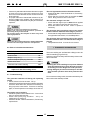
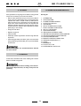
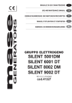
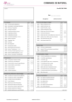
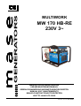
mase
GENERATORS
I
GB
D
E
F
FIN
MULTIWORK
MW 170 HB-RE
230V 3~
MANUALE DI USO E MANUTENZIONE
USE AND MAINTENANCE MANUAL
GEBRAUCHSANWEISUNG UND WARTUNGSVORSCHRIFTEN
MANUAL USO Y MANTENIMIENTO
MANUEL D’INSTRUCTIONS ET D’ENTRETIEN
KÄYTTÖ- JA HUOLTO-OPAS
REV.0 MC. 15-01-02
cod.42056
m a s e
MW 170 HB-RE 230V 3~
NR.000000
MASE GENERATORS S.p.A.
Tel.0547/354311
Fax 0547/31755
DICHIARAZIONE CE DI CONFORMITA'
EC DECLARATION OF CONFORMITY
Fabbricante/Manufacturer: MASE GENERATORS S.p.A.
Indirizzo /Address : Via Tortona 345, Pievesestina (FC)
Il sottoscritto Luigi Foresti in qualità di direttore tecnico della MASE GENERATORS S.p.A., dichiara sotto la
propria responsabilità che il gruppo elettrogeno modello .................... :
The undersigned Luigi Foresti as MASE GENERATORS S.p.A. technical manager declares, under his sole
responsability, that the generator model................:
Codice / Code
Descrizione / Model
No. matricola / Serial No.
E' conforme alle disposizioni delle Direttive di seguito elencate :
CEE 89/392 (come emendata delle Direttive CEE 91/368 e CEE 93/44)
CEE 89/336 (come emendata delle Direttive CEE 92/31)
CEE 73/23 modificata da CEE 93/68.
Corresponds to the requirements of the following EEC Directives :
89/392/EEC (as amended by the Directive 91/368/EEC and 93/44/EEC)
89/336/EEC (as amended by the Directive 92/31/EEC )
73/23//EEC as amended by 93/68/EEC.
Cesena,
/
/
......................................................
Direttore Tecnico
Technical Director
MASE GENERATORS S.p.A. Sede legale ed Amm.: 47023 CESENA (FC) ITALY - Via Tortona, 345 - C.F./P.I. 00687150409 Cap. Soc. milioni 1250
interamente versato - Registro Società Tribunale Forl' n. 6818 - CCIAA Forl' n.164063 - c.c.p. n. 11541471 - EXPORT FO n. 006368
Fig.1
2
m a s e
2
MW 170 HB-RE 230V 3~
1
3
4
5
GENERATORS
6
7
8
9
7
8
9
7
8
11
10
9
12
14
SERIAL No.
13
Fig.2
3
m a s e
MW 170 HB-RE 230V 3~
E
A
10
2
M
3
1
4
5
G
14
16
15
12
11
6
7
8
H
C
9
D
B
F
L
Fig.3
4
m a s e
MW 170 HB-RE 230V 3~
2
1
1
2
3
Fig.4
1
Fig.5
2
3
S.A.E
Service
Grade
Fig.6
5W
5W30
10W
MAX
10W30
20W
20W40
20
30
-30
MIN
-20
-10
40
0
10
20
30
o
Ambient temperature ( C)
40
Fig.8
Fig.7
0.7 - 0.8
Fig.9
5
m a s e
+
3x80 µF
3
-
1
MW 170 HB-RE 230V 3~
Fig.10
CODE 45225
6
m a s e
GB
MW 170 HB-RE 230V 3~
INDEX
1
1.1
1.2
1.3
1.4
1.5
1.6
1.7
1.8
1.9
1.10
GENERAL INFORMATION ...................................................................................... 18
Purpose and field of application of the manual ......................................................... 18
Symbols ................................................................................................................. 18
Reference documents ............................................................................................. 19
Facsimile of CE declaration of conformity ................................................................ 19
Reference regulations and legislative provisions ...................................................... 19
Marking ................................................................................................................... 19
Machine identification .............................................................................................. 19
Configurations ......................................................................................................... 19
Composition of the motor welding sets .................................................................... 20
Instrument panel ..................................................................................................... 20
2
2.1
2.2
2.3
TECHNICAL CHARACTERISTICS .......................................................................... 20
General characteristics ........................................................................................... 20
Welding graph ......................................................................................................... 20
Tables of technical characteristics ........................................................................... 20
3
3.1
3.2
3.3
SAFETY REGULATIONS ........................................................................................ 21
General precautions ................................................................................................ 21
Prescriptions for safety during installation and setup ............................................... 21
Connecting the motor welding set to earth .............................................................. 21
4
4.1
4.2
4.3
4.4
4.5
4.6
4.7
4.8
USING THE MOTOR WELDING SET ..................................................................... 22
Positioning .............................................................................................................. 22
Preliminary checks ................................................................................................. 22
Refuelling ................................................................................................................ 22
Starting the engine .................................................................................................. 22
Use as AC generator ............................................................................................... 23
Use as welder ......................................................................................................... 23
Using the remote control (optional) .......................................................................... 23
Stopping .................................................................................................................. 23
5
PROTECTIONS AND WARNING SIGNALS ............................................................ 24
6
6.1
6.2
6.3
6.4
6.5
6.6
6.7
MAINTENANCE ...................................................................................................... 24
Preamble ................................................................................................................ 24
Ordinary engine maintenance .................................................................................. 24
Engine oil change ................................................................................................... 24
Spark plug maintenance .......................................................................................... 24
Air filter cartridge cleaning/replacement ................................................................... 24
Scheduled maintenance table ................................................................................. 25
Troubleshooting ....................................................................................................... 25
7
TRANSPORT AND HANDLING .............................................................................. 26
8
STORAGE .............................................................................................................. 26
9
SCRAPPING .......................................................................................................... 26
10
WIRING DIAGRAM ................................................................................................ 26
17
m a s e
GB
MW 170 HB-RE 230V 3~
1 GENERAL INFORMATION
Carefully consult this manual before proceeding with any operation on the generator.
FAILURE TO RESPECT THE SPECIFICATIONS CONTAINED IN THIS USE AND MAINTENANCE
MANUAL WILL RESULT IN FORFEITURE OF THE GUARANTEE ON THE PRODUCT
1.1 Purpose and field of application of the manual
Thank you for choosing a MASE product.
This manual has been drawn up by the manufacturer with the purpose of providing essential information and instructions
for proper use and maintenance in conditions of safety and constitutes an integral part of the generator equipment. The
manual must be kept safely, protected from any agent which might damage it, for the entire life of the generator and
must accompany the generator if transferred to another user or owner.
The information contained in the manual is addressed to all those persons involved in the operating life cycle of the
generator, and is necessary to inform both those who effectively carry out the different operations and those who
coordinate the activities, arrange the necessary logistics and regulate access to the place where the generator will be
installed and operated.
The manual defines the purpose for which the generator was constructed and contains all the information necessary
to guarantee safe and proper use.
Constant observance of the instructions contained in this manual guarantees the safety of the operator, operating
economy and a longer life of the generator.
It is warmly recommended to carefully read the contents of this manual and the reference documents; only thus can
regular functioning and reliability of the generator be guaranteed over time, and protection against damage to persons
or things.
The drawings are provided by way of example. Even if the generator in your possession differs considerably from the
illustrations contained in this manual, the safety of the generator and the information provided are nevertheless
guaranteed.
To facilitate consultation, it has been divided into sections identifying the main concepts; for a quick look at the topics,
consult the index.
Note: the information contained in this publication is correct at the time of printing. The manufacturer in his pursuit
of a policy of constant development and upgrading of the product reserves the right to make modifications without prior
notice.
1.2 Symbols
Those parts of the text not to be ignored are highlighted in bold type preceded by a symbol, as illustrated and defined
below.
Indicates that particular attention must be paid in order to prevent running into serious danger which
could lead to death or possible hazards to the health of personnel.
A condition which may occur during the lifetime of a product, system or plant considered at risk
regarding damage to persons, property, the environment or economic loss.
Indicates that particular attention must be paid in order to prevent serious consequences which
could result in damage to tangible goods, such as the resources or the product.
Instructions of particular importance.
18
m a s e
GB
1.3 Reference documents
MW 170 HB-RE 230V 3~
– Part 1: Residential, commercial and light-industry
environments.
- Part 2: Industrial environment.
The instructions for use provided with each motor welding
set are made up of a collection of documents of which this
manual represents the General Part. Normally, the following documents are provided:
EN 50082-1/2 (Electromagnetic compatibility): General
regulation on immunity.
- Part 1: Residential, commercial and light-industry
environments.
- Part 2: Industrial environment.
a - CE declaration of conformity.
b - Instruction manual for use of the motor welding set
(this manual)
c - Wiring diagrams of the control panels and power
board.
d - Engine use and maintenance manual
e - Warranty card
f - List of Mase Service Centres
89/392/EEC and subsequent amendments contained in
the Directives 91/368/EEC, 93/44/EEC and 93/68/EEC:
Essential machine requirements for safety and health
protection (“Machine” directive).
73/23/EEC and subsequent amendments contained in
the Directive 93/68/EEC: Guarantee of safety of electrical
material intended for use within certain voltage limits
(“Low Voltage” directives).
1.4 Facsimile of CE declaration of conformity
The generators constructed by MASE, intended for
countries in the European Community, are in conformity
with the applicable EEC Directives (see 1.5) and are
furnished with an EC declaration of conformity (Fig. 1).
1.6 Marking
1.5 Reference regulations and legislative provisions
The generator identification plate carries all the identification data in conformity with ISO 8528 and in accordance
with the provisions for CE marking for those cases where
required. Below is a facsimile of the identification plate
fixed on the control panel of each generator (Fig.2)
All the MASE diesel generators are designed and manufactured in compliance with the legislation in force.
The generator and its components are constructed in
accordance with the following applicable regulations and
directives:
1.7 Machine identification
See Fig.2
1 – Manufacturer
2 – Machine code
3 – Year of construction
4 – Power during welding
5 – Power factor
6 – Declared frequency
7 – Continuous power
8 – Nominal tension
9 – Nominal current
10 – Weight
11 – Performance rating
12 – Serial number
EN 292-1/2: Machine safety regulations.
General design principles.
EN 294: Machine safety regulations.
Safety distances to prevent contact of dangerous parts
with the upper limbs.
ISO 3046: Alternate internal-combustion engines.
IEC 34-1: Rotary electric machines.
ISO 8528-1: Alternate current generators driven by alternate internal-combustion engines.
The machine code number, the serial number and the
year of construction must always be quoted when
contacting the manufacturer for information, requests
for spare parts, etc.
EN 60204-1 (CEI 44-5):
- Machine safety.
- Electrical equipment of machines.
EN 60439-1 (CEI 17-13/1): Assembled protection and
manoeuvring equipment for low voltage (low-voltage panels).
1.8 Configurations
One of the characteristics of the Multiwork series is that
it can be supplied in different configurations:
EN 50081-1/2 (Electromagnetic compatibility): General
regulation on emission
- without trailer (Fig.2)
- on trailer with handles
19
m a s e
MW 170 HB-RE 230V 3~
GB
2.2 Welding graph
1.9 Composition of the motor welding sets
See Fig.2
The motor welding sets are essentially made up of the
following components:
A
B
C
D
E
F
G
H
H
L
M
-
Frame
Engine
Fuel tank
Recoil assy
Muffler
Alternator
Control panel
Taps panel
Inductor
Diode bridge
Lift up
1.10 Instrument panel
2.3 Tables of technical characteristics
Each motor welding set is fitted with an instrument panel
for the controls with the following components:
GENERAL CHARACTERISTICS
800x530x520 mm
DIMENSIONS (L x W x H)
DRY WEIGHT (WITHOUT BATTERY)
98 Kg
CAPACITA' SERBATOIO CARBURANTE
6,5 Liters
MAX. INCLINATION
25°
See Fig.3
1
2
3
4
5
6
7
8
9
10
11
-
Voltmeter
Welding current regulation
Welding arc regulation
Remote control connector
Hour counter
Three-phase outlet,EEC 16A 230V 3P+GND
Differential switch 4P
Single-phase outlet, EEC 16A 230V 2P+GND
Earth connection terminal
48V Outlet (AC)
Welding couplings (+/-)
TYPE
ALTERNATOR
ASYNCHRONOUS, THREE-PHASE,
SELF-EXCITED AND SELF-REGULATING
INSULATION CLASS
F
WELDER
CONTROL
CURRENT AND SERVICE FACTORS
FLASHOVER VOLTAGE
ELECTRODE DIAMETER
ELECTRONIC
145 at 35% - 135 at 60%
68 V
4 mm MAX
GENERATOR
THREE-PHASE POWER (230V)
SINGLE-PHASE POWER (230V)
48 V POWER
FREQUENCY
VOLTAGE STABILITY
FREQUENCY STABILITY
POWER FACTOR
2 TECHNICAL CHARACTERISTICS
2.1
General characteristics
4.600 VA
3.000 VA
2.000 VA
50 Hz
10%
3%
0,8
ENGINE
TYPE
MODEL
COOLING
NUMBER OF CYLINDERS
DISPLACEMENT
POWER SUPPLY
POWER
SUCTION
ENGINE RPM
OIL SUMP CAPACITY
FUEL CONSUMPTION
STARTING
The motor welding sets of the Multiwork MW70 HB-RE
series (HONDA powered) are designed for use in the
industrial field in the welding sector.
The 4-stroke gasoline engine with air cooling designed
for heavy duty is extremely reliable and robust.
Particular attention has been paid to the degree of protection against external agents, engine protection and
protection of the electrical parts against overload or overheating.
The alternator is the 2-pole asynchronous type with excitation capacitors and is fitted with electronic control
of the welding current. It is able to deliver direct current
for welding, and 230V three-phase, 230V single-phase
and 48V single-phase alternate current.
20
HONDA
GX 270
AIR
1
270 cm3
GREEN GASOLINE
6 KW / 8,2 HP
NATURAL
3000 rpm
1.1 Litres
230 g/HP/h
MANUAL
m a s e
GB
MW 170 HB-RE 230V 3~
3 SAFETY REGULATIONS
- Do not allow access to persons wearing a pacemaker because of possible electromagnetic interference with the device.
- In the event of fire, use a homologated fire extinguisher and never use water.
3.1 General precautions
Before starting the motor welding set and before starting
any lubrication or maintenance operation, it is indispensable for the staff responsible to read and understand all
the WARNINGS and all the CAUTION and DANGER indications listed in this manual and in the supplementary
documentation furnished.
Nevertheless, the manufacturer cannot foresee all the
possible circumstances which may lead to potential risks
in the effective conditions of use of the generator.
Any operations and/or procedures for maintenance not
expressly recommended or indicated in the user manuals must always be notified to and approved by the Manufacturer.
In the event that a procedure not specifically recommended needs to be applied, the user is responsible for
assuring that such procedure is safe and does not cause
harm to persons or things.
When using the motor welding set, bear in mind that
in wet or very humid places and in confined
conduction spaces it is obligatory to comply with
Articles 313 and 318 of Presidential Decree No. 547
27/04/55, as well as CHAP. 11 SECT. IV of the CEI 648 regulation.
3.2 Prescriptions for safety during installation and
setup
- The personnel in charge of installation and starting
of the motor welding set must always wear a
protective helmet; wear safety shoes and overalls.
- Immediately change wet overalls.
- Use protective gloves.
- Do not leave disassembled parts, tools or anything
else not forming part of the system on or near the
engine.
- Never leave inflammable liquids or cloths soaked
in inflammable liquids in proximity of the motor
welding set, near electric equipment (including
lamps) or parts of the electrical system.
- Take the necessary precautions to prevent the
danger of electrocution.
- Check that the earthing system has been installed
and constructed in accordance with regulations.
The manufacturer declines all responsibility for damage
to persons or things deriving from inobservance of the
safety regulations.
Carefully examine the safety warning plates on the machine and respect the relevant instructions.
- Do not permit incompetent persons or without adequate
training to use the motor welding set.
- Do not permit children or animals to approach the motor welding set when it is in operation.
- Do not access the motor welding set with wet hands,
since it is a potential source of electric shock if improperly used.
- Any inspections of the motor welding set must be carried out with the engine off. Inspections with the engine on are to be carried out by specialised personnel
only.
- Exhaust gas contains carbon monoxide and other noxious residues. Never operate the generator in inadequately ventilated places.
- Do not operate the motor welding set near places with
a danger of explosion or fire.
- Refuelling must be carried out exclusively with the engine off.
- The motor welding set must be connected to earth using a copper wire of suitable cross-section (see section 3.3).
3.3 Connecting the motor welding set to earth
For the safety of the users, the earth connection of the
motor welding set must always be carried out paying
particular attention to the cable cross-section used, which
must be at least 10 mm2.
For the connection of the earth cable use the dedicated
terminal on the control panel (Fig. 3 Ref. 9).
The manufacturer is not responsible for any damage
caused by failure to earth the system.
21
m a s e
MW 170 HB-RE 230V 3~
GB
4 USING THE MOTOR WELDING SET
tor is not started on load;
- that the fuel pipes are undamaged and properly connected;
- that there are no electrical connections in a bad state.
4.1 Positioning
The motor welding sets of the Multiwork MW170 HBRE series must be positioned as horizontally as possible, i.e. placed on a flat surface or made to sit horizontally by placing shims under the frame.
4.3 Refuelling
Refuelling must be carried out with extreme care, ensuring that fuel does not overflow from the engine tank and
respecting the maximum level.
When refuelling has been completed, carefully close the
fillercap (Fig.4 Ref.1)
If necessary with the versions with trailer, use some
chocks on both wheels.
The engine functions properly if it does not exceed
a maximum inclination of 25°, both on the longitudinal and the transversal axis. Should the engine be
operated in conditions at a greater inclination, there
is a risk of insufficient lubrication or suction of engine oil from the air filter.
- Fuel is toxic and inflammable and must therefore
be kept in special airtight containers and stored in
inaccessible places.
- Refuelling must always be carried out with the engine off.
- Do not smoke and do not use open flames during
refuelling.
- Refuel in well-ventilated places.
- Avoid contact of fuel with the skin and do not inhale the fumes.Vaseline.
4.2 Preliminary checks
Before beginning with any starting procedure, it is extremely important to become “familiar” with the motor
welding set and its controls. Furthermore, a visual inspection must be carried out on the machine and the
installation.
Any source of potential or real danger must be eliminated before proceeding.
Identify the position of the Ignition / stopping key,
switches and other emergency systems on the motor
welding set.
Learn the special emergency procedures relative to
the installation in question.
Identify the position of the fire extinguisher or other
protection and emergency devices and learn their functioning.
Identify any sources of danger such as fuel, engine
oil or acid solution leaks, condensate in the drip caps,
high voltage, high pressure.
Ensure that the motor welding set is clean and that
the surrounding areas are clean and free of obstacles.
Check that there are no obstructions in the inlets and
ventilation ducts.
Check that the exhaust pipe is not oriented against
obstacles, or make sure that these are at least two
metres away.
Check that the earth connection has been carried out
properly.
4.4 Starting
Before starting the generator check that all the utilities
are off to prevent putting the still cold engine under stress.
The generator engine has been calibrated, in idle, to 3240
rpm equal to 54 Hz, as the engine stabilises at about 3000
rpm equal to 50Hz with a load. For this reason, the
accelerator lever, (Fig. 3, ref. 14), must never shift for any
reason, since the output voltage, frequency and power
values of the generator would be compromised.
To start proceed as follows.
• Disconnect the outlets, (alternatively the
magnetothermal differential switch), to prevent putting
the still cold engine under stress.
• Turn the engine stop switch to position "I", (Fig. 3,
ref. 15).
• Open the fuel cock by turning the lever shown in Fig.
3, ref. 12.
• If the engine is cold, close the air start lever by turning
it as shown in Fig. 3, ref. 16, before attempting to start.
If the engine is hot the start lever need not be turned.
• Proceed by firmly pulling the self-winding cord, (Fig. 3,
ref. D), to start engine rotation.
• Repeat the operation if the engine has not started at
the first attempt.
• As soon as the engine has started, gradually return
the air start lever to the original position.
At first starting of the motor welding set, after having
done any type of maintenance work, it is always good
practice to check:
- the oil level by means of the dipstick (Fig.2 Ref.13);
- that all the electrical utilities are off so that the genera-
22
m a s e
GB
MW 170 HB-RE 230V 3~
Bear in mind that for use of the
To prevent damage to the self-winding cord of the engine,
never release it abruptly after having pulled it out fully,
but guide it until complete rewinding.
majority of basic, rutile and basic cellulose electrodes, the electrode holder clip is connected to the
“+” outlet while for rutile acid and rutile cellulose
electrodes the electrode holder clip is connected to
the “-” outlet.
For the best results, refer to the instructions normally
given on the electrode packaging.
4.5 Use as AC generator
Before powering any utility, leave the engine to run without applied load for at least five minutes so that it gradually reaches the operating temperature. This will guarantee longer life of the engine and eliminate the risk of
seizures.
Each motor welding set is equipped with:
During the first 50 hours of operation, do not draw
more than 60% of maximum suppliable power and
frequently check the oil level with the graduated dipstick (Fig.2, Ref.13). The oil level must always be between the MAX and MIN notches on the dipstick
(Fig.8).
- a three-phase outlet, EEC 16A 230V 3P+GND
- a single-phase outlet, EEC 16A 230V 2P+GND
- 48V AC couplings
The available power is as indicated on the adhesive label
carrying the technical characteristics (Fig.2).
4.7 Using the remote control (optional)
The welding current can be remote-controlled by using
the special control (Fig.7, Ref. 6 ).
To do this the remote control plug (Fig.6, Ref.1) must be
inserted in the special connector (Fig.3, Ref.4) located
on the control panel . In this way the control device on
the control panel of the generator are overridden and those
of the remote control enabled. The welding current is
regulated in the same way as described in the preceding paragraph, by means of the potentiometer (Fig.6,
Ref. 2). The regulation of the arc of welding, is taken
place always through the potentiometer (Fig.3, Ref. 2).
- The sum of absorption of all the utilities connected
to the motor welding set must never exceed the
continuous power value of the motor welding set.
- During the first 50 hours of operation, do not draw
more than 60% of maximum suppliable power and
frequently check the oil level with the graduated
dipstick (Fig.3, Ref.1). The oil level must always
be between the MAX and MIN notches on the dipstick (Fig.8).
4.6 Use as welder
The remote control comes with a 20 m cable. Should
it be necessary to modify the length, “MASE” technical service must first be consulted.
The motor welding sets of the Multiwork MW 170 HBRE may be used as direct current generators for arc
welding. Before doing any welding, leave the engine to
idle for at least five minutes so that it gradually reaches
the operating temperature. This will guarantee longer
life of the engine and eliminate the risk of seizures.
The welding cables must be connected to the special
couplings (Fig.3, Ref.11) respecting the polarity indicated.
Regulate the welding current with the regulating knob
(Fig.3, Ref.3):
- turning clockwise, the current increases,
- turning anticlockwise, the current decreases.
The welding arc is regulated with the regulating knob
(Fig.3, Ref.2):
- turning clockwise, the arc penetration increases,
- turning anticlockwise, the arc penetration decreases.
4.8 Stopping
Before stopping the engine it is recommended to run it
without load for a few minutes and with the accelerator
at minimum, thus allowing the inside temperature of the
engine and the alternator to gradually reduce.
23
m a s e
MW 170 HB-RE 230V 3~
GB
5 PROTECTIONS AND WARNING SIGNALS
Daily check the oil level with the graduated dipstick
(Fig.2, Ref. 13)
The oil level must always be between the MAX and
MIN notches on the dipstick (see FIG.8).
The generators are equipped with a series of protections
which safeguard them against improper use and faults
which may compromise integrity and are:
6.3 Engine oil change
Low oil pressure protection
The engine is provided with oil for petrol engines with
viscosity SAE 10W/30.
Intervenes switching off the unit when sump oil level gets
down to the minimum. Its intervention is not signaled
by warning lights, therefore, in case machine stops it is
always necessary to check oil level to make sure that it
is not the cause of generator’s stopping.
Add the necessary quantity of oil to start up the
generator again.
Always check correct viscosity of lubricating oil in relation
to range of temperatures of the environment in which the
generator works, as indicated in table of Fig. 7.
Protection against short-circuit and overload
In case of short-circuit and overloaded, the motor welding
sets are autoprotette, disconnect in case of short-circuit
and limiting the tension of exit in case of overload
arriving up to the disconnect. Eliminating the cause of
the short-circuit or overloaded, he will restore initial
condition. The motor welding sets are provisions of a
general differential interrupter, that pour earth in case of
dispersion of tide, it has the assignment to interrupt the
disbursement of the tide to all the taking. (Fig.3, rif.7)
Top-up and fill through the hole indicated in Fig. 2, ref. 13.
For replacement of engine oil, remove the tap located on
the bottom part of the oil sump, (Fig. 2, rif. 14), and let it
flow into a suitable container.
It is recommended to drain the oil when it is still
sufficiently warm to flow easily.
Close the drain tap and add the necessary quantity of oil
in the sump.
Oil sump capacity is 1.1 lt.
6 MAINTENANCE
6.1
• Do not disperse of exhausted oil in the environment as
it is a polluting product.
• Deliver the exhausted engine oil to proper disposal
collecting centers.
• The first engine oil change must be carried out after
the first 20 working hours and, afterwards, at intervals
of 50 working hours.
Preamble
Any maintenance operation on the motor welding
set must be carried out with the engine off and leaving it to cool down sufficiently, and must only be
carried out by authorised and suitably trained personnel.
6.4 Spark plug maintenance
Spark plug type:
NGK - BR6HS
DENSO - W20EPR-U
It is necessary to periodically remove the carbon residues,
that, due to use, deposit on the spark plug, by using a
small metal brush or specific detergent.
Adjust distance of spark plug electrodes setting a value
of 0.7 - 0.8 mm, (Fig. 9).
It is recommended to scrupulously follow the instructions in the manual provided by the engine Manufacturer with each motor welding set.
It is important to regularly inspect and carry out maintenance on the motor welding set. The frequency of maintenance should be decided on the basis of the number
of hours of operation indicated in the table at point 6.6.
6.5 Air filter cleaning/replacement
For good operation and for a long life of the engine, it is
important to periodically clean and replace the air filter.
A non efficient filter could be the cause of loss of power of
the engine and excessive exhaust smoke.
To clean or replace the air filter, follow the steps here
below.
• Remove the filter holder cover, (Fig. 4, ref. 2), undoing
the butterfly retaining nut (Fig. 4, ref. 3).
• Extract the filter complete with the two elements: the
sponge element and the paper element.
• The sponge element is simply washed with a domestic
detergent or with a low-flammable solvent.
6.2 Ordinary engine maintenance
The periodic maintenance operations to be carried out
on the engine are indicated in the table at point 6.6.
For more detailed information consult the manual provided by the engine manufacturer with each motor welding set.
24
m a s e
GB
MW 170 HB-RE 230V 3~
There is high smoke emission from the exhaust.
• Check the air filter. Clean its elements or, if necessary,
replace them.
• Check that the oil level does not exceed the MAX
notch. Bring it down to the correct level.
• Leave to dry well and soak the clean element in engine
oil, then wring it out to remove the excess oil, since
too much oil in the element causes excessive smoke
at the exhaust.
• The paper element is cleaned with a blast of dry air,
from the inside to the outside, with a pressure not
exceeding 2 bar. Should it be very dirty or have holes,
replace it.
The alternator voltage is too low.
• Check that the engine rpm is 3240 without applied
loads. Consult an authorised Service Centre.
• Check the state of the air filter. Clean or replace if
necessary.
Clean the air filter every 50 hours of operation.
Reduce the intervals if the generator operates in
particularly dusty environments.
On average replace the complete air filter every three
cleaning operations.
The generator does not deliver power to the outlets
but the voltmeter indicates that voltage is present.
• Check that the magnetothermal differential switch, or
a magnetothermal switch, is in the ON position.
Never clean the air filter with petrol or highly inflammable
solvents since this might cause fire or explosions.
The generator does not deliver power to the outlets
and the voltmeter does not indicate that voltage is
present.
• Likely alternator fault. Consult Service Centre.
6.6 Table of scheduled maintenance
OPERATION
Check engine oil level in sump
Clean air filter
Replace sump oil (*)
Clean and adjust spark plug electrode
Check valve slack
Fuel tank and screen cleaning
(*)
7 TRANSPORT AND HANDLING
HOURS
The motor welding set are fitted with a lifting hook to be
used for handling (Fig.3 Ref. M).
Hook the machine carefully and lift it slowly without sudden movements.
8
50
100
100
300
300
- Hooking the motor welding set at points different
from that indicated may cause damage to the motor welding set or be dangerous to the operators.
- During lifting all personnel must keep a safe distance and the operators must wear protective helmets.
For the first time,
replace oil after 20 working hours.
6.7 Troubleshooting
For movement on the ground, the version with trolley can
be moved on the wheels provided.
The generator switches off during the operating
period.
• Check if there is fuel in the tank. Fill up.
• Check if the low oil level protection has been activated,
check the level and if low, add the oil necessary to
bring it up to the correct level. There are no warning
lights; a visual inspection must always be carried out.
The engine runs irregularly.
• Check the position of the starter lever. It must have
been re-opened after starting.
• Check the spark plug condition. Carry out
maintenance or replace it.
• Check the air filter. Clean its elements or, if necessary,
replace them.
25
m a s e
MW 170 HB-RE 230V 3~
GB
8 STORAGE
10 WIRING DIAGRAM REFERENCES
If the generator is not going to be used for a long period
of time it is necessary to proceed as follows.
See Fig.10
• Remove the spark plug and pour from 3 to 5 cm3 of
engine oil in the spark plug hole on the head of the
cylinder and make a couple of start-up attempts but
without turning on the generator; this will make the
engine turn a few times and let the oil expand and
lubricate cylinder and piston thus preventing rust on
cylinder and valve. After the above operation, put back
spark plug in its housing.
1
2
3
4
5
6
7
8
9
10
11
12
13
14
15
16
17
18
19
• Empty the fuel tank
• Replace engine oil
• Clean air filter
• Externally clean the generator unit removing dust and
impurities.
• Protect the generator unit with a nylon cover and stow
away positioning it horizontally in a dry and ventilated
environment.
Refer to the engine use and maintenance manual
for more details.
9 SCRAPPING
At the end of its lifetime the motor welding set must be
taken to official scrapyards.
Do not dispose of the motor welding set at household refuse disposal sites, as many of its parts are
polluting.
26
ALTERNATOR
HOUR COUNTER
POWER TERMINAL BOARD
OUTLET 2P+GND 16A
VOLTMETER
SET OF THREE CAPACITORS
EARTH CONNECTION SCREW
48V A.C. COUPLINGS
SCR DIODE BRIDGE
WELDING ADJUSTMENT CARD
WELDING ADJUSTMENT POTENTIOMETER
ARC ADJUSTMENT POTENTIOMETER
POTENTIOMETER CARD
REMOTE-CONTROL CONNECTOR
WELDING COUPLINGS (+/-)
SHUNT
IMPEDENCE
OUTLET 3P+T 16A
DIFFERENTIAL SWITCH 4P