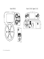
1
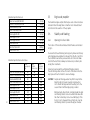
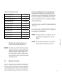
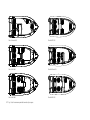
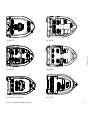
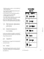
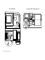
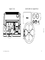
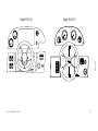
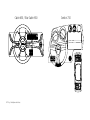
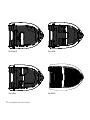
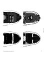
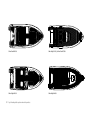
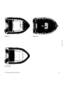
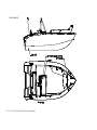
Omistajan käsikirja
Användarhandbok
Owner’s Manual
Eignerhandbuch
Manuel du propriétaire
2
ENGLISH
Silver
Owner’s Manual
3
Preface
Dear Silver boat owner! Thank you for buying a Silver boat. We hope
that you will enjoy it!
This Owner’s Manual is intended to help you use your boat safely. It
provides a detailed description of the boat and related systems and
accessories as well as information about the proper operation and
care of the boat. Please read this manual carefully before using the
boat for the first time.
Naturally, the Owner’s Manual is no course in seamanship or boating safety. If this is your first boat or you have traded your old boat
in for a new type that you are not familiar with, make sure, for
you own comfort and safety, that you gain enough experience in
handling and using the boat before accepting command. The dealer, boating clubs and national motor-boating and sailing associations will be happy to recommend local boating schools or competent instructors.
Make sure that the design category of your boat will meet the
predicted wind conditions and wave heights and that you and your
crew can handle the boat in such conditions. The wind and wave
conditions corresponding to design categories A, B, and C range
from a storm to strong winds involving a risk of exceptional waves
and gusting. Although your boat is designed for such conditions,
safe operation requires an able, trained crew and a well-maintained
boat.
4
This Owner’s Manual is not a detailed maintenance or troubleshooting guide. In case of problems, contact the manufacturer or your
dealer. Always have the boat serviced and repaired and any alterations done by qualified personnel. Any modifications that may
affect the safety of the boat should be evaluated, carried out and
documented by a qualified person. The manufacturer accepts no
liability for unauthorised modifications.
In some countries, a special boating licence or authorization may
be required to operate the boat. These countries may also apply
other additional regulations.
Always keep the boat in good condition. Consider wear and tear
due to ageing, rough treatment or misuse. Any boat – irrespective
of its strength – may be seriously damaged if it not used properly.
Misuse is not part of safe boating. Always adjust your speed and
direction of travel to the prevailing swell.
If your boat is equipped with a life raft, read its operating instructions with care. The boat should always have the appropriate safety equipment (life vests, safety harness, etc. ) according to the type
of boat, weather conditions, etc. In some countries, such equipment is compulsory. The crew should be familiar with the use of all
the safety equipment and emergency manoeuvres (for example, reboarding a person falling overboard, towing, etc.). Sailing schools
and clubs organise sea rescue exercises on a regular basis.
All persons onboard the boat should wear suitable flotation device
(life vest / boating vest) when on deck. Note that in some countries it
is mandatory to wear a flotation device at all times when onboard.
ENGLISH
KEEP THIS OWNER’S MANUAL IN A SAFE PLACE AND GIVE IT TO THE
NEXT OWNER IF YOU SELL THE BOAT.
5
Before departure
Read this Owner’s Manual carefully.
Always check the following items before departure:
Prevailing weather and weather forecast
Fuel
Make sure that you have enough fuel, including reserves in case of
foul weather.
Engine and equipment
Consider wind, wave height, and visibility. Is the design category of
your boat, its size and accessories as well as the skills of the master
and crew sufficient for the waters in which you intend to travel? In
strong winds and high seas, all hatches must be closed to prevent
water from entering the boat.
Check the operation and condition of the steering system, electrical equipment and the battery and carry out the daily checks specified in the engine manual. Ensure the seaworthiness of the boat by
checking for fuel and water leaks, make sure that all the safety gear
is onboard, etc. Make sure that the water level in the bilge is at its
minimum.
Load-carrying capacity
Ventilation
Do not overload the boat, and distribute the load evenly. Do not
place heavy objects in elevated positions because they may jeopardise the stability of the boat.
If the engine compartment in your boat is equipped with a fan, let it
run for at least 4 minutes before starting the engine. Start the engine following the manufacturer’s instructions. Ensure adequate
ventilation around fuel tank(s) to reduce the risk of fire.
Passengers
Make sure that there are enough life vests for all onboard. Before
departure explain the duties of every passenger during the trip.
6
Stowage of goods
Make sure that all the goods are secured so that they cannot move
in heavy seas and strong winds.
Nautical charts
If you are not navigating a route that you know by heart, make sure
that you have enough charts to make the trip safely.
Departure and landing manoeuvres
Agree with the crew members who will manage what rope. Make
sure that mooring lines, etc., cannot get entangled in the propeller
when departing or landing.
ENGLISH
Consult the engine manual for information concerning the engine.
7
Contents
8
1
General
145
2
Definitions
145
3
Warranty
145
4
Commissioning
4.1 Registration
4.2 Insurance
4.3 Training
146
146
146
146
5
Characteristics and operation of the boat
5.1 General
5.2 Basic boat data
5.3 Maximum number of persons the boat is
designed to carry
5.4 Loading
5.5 Engine and propeller 5.6 Stability and flooding
5.6.1 Openings in hull and deck
5.6.2 Bilge pumps and drainage
5.7 Prevention of fire and explosion 5.7.1 Engines
5.7.2 Other fuel-burning systems
5.7.3 Fire protection
5.8 Electrical system
146
146
146
147
147
148
148
148
149
153
153
153
153
153
5.9 Handling characteristics
154
5.9.1 Driving at high speeds
154
5.9.2 Visibility from the steering position
154
5.10 Proper seamanship – recommendations and instructions
155
5.10.1 Protection from falling overboard and
means of re-boarding
155
5.10.2 Stowage of life raft
155
5.10.3 Ventilation
155
5.10.4 Securing loose items
161
5.10.5 Respect for the environment
161
5.10.6 Anchoring, mooring and towing
161
5.10.7 Trailering
162
6
Maintenance and winterizing
6.1 Measures before winter docking
6.2 Washing and cleaning
6.3 Winter storage and servicing
6.4 Measures before launching
163
163
163
163
164
7
Repairs
164
Appendices
171
General
This Owner’s Manual helps you get to know your boat and learn
about its characteristics, maintenance and servicing. The manuals for the accessories installed in the boat are included, and reference is frequently made to them. Naturally, you can supplement
this manual with the manuals for any additional accessories you
may have retrofitted. Space is provided for your own notes at the
end of the manual.
2
Definitions
The following texts are used in this manual to indicate risk or danger:
DANGER! Means that there is a serious risk of injury or death
unless proper precautionary action is taken.
WARNING! Means that there is a risk of injury or death unless
proper precautionary action is taken.
3
Warranty
The manufacturer gives the boat and the accessories installed at
the boatyard a two-year warranty in accordance with the terms
indicated on the warranty card. Warranties for the following
components are given by the respective manufacturers:
– engine and drive
– trim tabs
– stove, refrigerator, and heater
– compass
– instruments
– navigation equipment.
The warranty certificates for these devices and the contact details
of the suppliers are attached. In case of inquiries concerning other
equipment, please contact
ENGLISH
1
TerhiTec Oy, Sorvitie 4, FI-63700 Ähtäri, Finland
Tel.+358 20 510 200, fax +358 20 510 201
[email protected]
CAUTION! Reminds of a safe procedure or highlights an unsafe
procedure that may lead to an injury or damage to the
boat or its components.
This manual makes use of the SI units of measurements. Other
units may be used in brackets in places.
9
4
Commissioning
4.1
Registration
Under the Finnish Boating Decree, motorboats with an engine with
an output at least 15kW or hull length at least 5,5 meters, must be
entered in the National Craft Register. For more details, contact the
local register office (maistraatti). A person operating a registered
boat must be at least 15 years of age.
4.2
Insurance
Boat insurance may cover damage sustained at sea or when the
boat is transported over land or docked. Check the insurance liability before the boat is lifted out of water. Indirectly, insurance may
also improve safety at sea: in case of an accident, you can concentrate on saving human life. Contact an insurance company for information about boat insurance.
4.3
Training
No one is born a master. Many books on boating and navigation are
available. Check about the possibilities of attending navigation and
boating courses. While they will get you started, true confidence
in handling, navigation, mooring and anchoring is only achieved
through long practice. It is also advisable to find out about the local
boating clubs and their activities.
10
5
Characteristics and operation
of the boat
5.1
General
This Owner’s Manual is not intended to be a complete servicing and
maintenance guide. However, it will help you get to know your boat
and its characteristics and operate it safely.
5.2
Basic boat data
The technical data on the various Silver boat models is listed in the
following table:
Design category:
Category C: Designed for voyages where conditions up to and including wind force 6 (Beaufort scale), or 14 m/s, and significant
wave heights of up to 2 m may be experienced (see Note below).
Such conditions may be encountered on open lakes, estuaries, and
coastal waters in reasonable weather conditions.
Category D: Designed for voyages where conditions up to and including wind force 4 (Beaufort scale), or 8 m/s, and significant wave
heights of up to 0.3 m may be experienced (with occasional wave
heights of 0.5 m). Such conditions may be encountered in sheltered
waters and coastal waters in good weather.
Main dimensions and capacities:
The boat’s length, beam, draught, total weight, etc., and tank capacities are indicated in the Technical Specifications in Appendix 1.
Builder’s plate:
A builder’s plate that shows some of the above information is affixed within the field of vision of the pilot. Supplementary data is
provided in the appropriate sections of this manual.
5.3
Maximum number of persons the boat
is designed to carry
The maximum numbers of persons the different Silver boat models
are designed to carry are indicated in the following table. The seats
intended for the passengers are indicated in Fig. 1.
WARNING! Never exceed the maximum number of passengers. Irrespective of the number of people onboard, the combined weight
of the passengers and equipment may never exceed the maximum
permissible load (see Loading). Always use the seats provided.
Maximum number of passengers:
Silver Fox Avant/DC/BR 485
Silver Wolf DC/Avant/BR 510
Silver Hawk BR/CC 540
Silver Shark BR/CC 540
Silver Eagle BR 650/CC 630
Silver Eagle WA 650
Silver Cabin 650
Silver Star Cabin 650
Silver Condor 730
5.4
5
6
7
7
7
7
7
7
8
Loading
ENGLISH
Note:
Significant wave height means the average height of the highest
1/3rd of the waves over a given period, which is equivalent to the
wave height estimated by an experienced observer. Waves of double that height may occasionally be experienced.
The maximum permissible load that Silver boats are designed to
carry include the following:
a)
total weight of the persons onboard (an adult is
assumed to weigh 75 kg and a child 37.5 kg )
b)
basic equipment
c)
weight of the liquids carried in portable containers
(water, fuel, etc.)
d)
total weight of the consumable liquids in integrated
tanks (water, fuel, etc. ) (with full tanks)
The recommended weight only includes the weight components
listed above.
WARNING: When loading things aboard, never exceed the maximum permissible load. Position the load carefully to
ensure the optimum balance of the boat (even keel).
Do not place heavy objects in elevated positions.
11
5.5
Maximum permissible load:
Silver Fox Avant/DC/BR 485
Silver Wolf DC/Avant/BR 510
Silver Hawk BR/CC 540
Silver Shark BR/CC 580
Silver Eagle BR 650
Silver Eagle CC 630
Silver Eagle WA 650
Silver Cabin 650
Silver Star Cabin 650
Silver Condor 730
465 kg
500 kg
615 kg
525 kg
675 kg
705 kg
675 kg
675 kg
600 kg
1005 kg
Maximum permissible load includes:
Basic
Fuel in
Fuel in
equipment, portable
integrated
kg
containers, kg tanks, kg
12
Silver Fox Avant/DC/BR 485
Silver Wolf DC/Avant/BR 510
Silver Hawk BR/CC 540
Silver Shark BR/CC 580
Silver Eagle BR 650
Silver Eagle CC 630
Silver Eagle WA 650
Silver Cabin 650
Silver Star Cabin 650
Silver Condor 730
10
10
10
11
15
15
20
20
20
25
40
40
80
100
100
100
100
100
100
250
Engine and propeller
The maximum engine outputs that may be used on Silver boats are
indicated in the following table. Follow the motor manufacturer’s
instructions in the selection of the propeller.
5.6
Stability and flooding
5.6.1
Openings in hull and deck
The location of thru-hulls and related shutoff valves are indicated
in Fig. 5.
To ensure that the self-draining works properly, make sure that any
extra baggage and equipment is removed from the floor and from
the container boxes before you leave the boat to the dock. Make
sure that the boat floats sideways as balanced as possible by balancing other load items.
Silver boats are lined with a self-draining fibreglass interior.
The self-draining outlets in the aft corners of the interior must be
kept open and free from debris to ensure drainage.
CAUTION! Despite self-drainage, water may find its way into the
bilge through motor well openings and inspection
doors. Check the bilge level before setting out to the
sea and drain it with the bilge pump provided.
On Silver Eagle, Silver Shark, and Silver Hawk, the deck
self-draining outlets can be closed with ball valves. On
the other models they can be closed with plugs. If the
boat is to carry a heavier-than-normal load, close the
self-draining outlets to prevent the ingress of water.
37 kW (50 hv)
45 kW (60 hv)
45 kW (60 hv)
75 kW (100 hv)
86 kW (115 hv)
130 kW (175 hv)
112 kW (150 hv)
130 kW (175 hv)
112 kW (150 hv)
112 kW (150 hv)
220 kW (300 hv)
With Silver Cab models, keep the cabin doors and
hatches closed in strong winds and heavy seas.
cuit breaker provided that the battery has been installed and connected. The electric bilge pump can also be operated from the
switch panel. The capacity of the bilge pump is about 45 litres/min.
Boats without a manual electric pump installed do not feature an
automatic emptying function: in this case, the pump is engaged by
a switch in the switch panel.
The electric bilge pump is operated from the switch panel described
in Section 5.8.
Carry out regular checks to ensure that the ends of the bilge pump
suction hoses are not blocked by debris.
WARNING! The bilge pump system is not designed for controlling
leaks resulting from running aground or other such
damage.
ENGLISH
Maximum permissible engine outputs:
Silver Fox Avant/DC 485
Silver Fox BR 485
Silver Wolf DC/Avant/BR 510
Silver Hawk BR/CC 540
Silver Shark BR/CC 580
Silver Eagle BR 650
Silver Eagle CC 630
Silver Eagle WA 650
Silver Cabin 650
Silver Star Cabin 650
Silver Condor 730
CAUTION! Check the bilge pump regularly for correct operation.
Remove any debris from the pump suction inlets.
WARNING! If you want to keep the cabin roof hatch open when under way, secure it in the open position with the locking
mechanism. Failing that, a sudden movement of the
boat may cause the roof hatch to close without warning and cause injuries. Secure all the other hatches and
doors in the same way.
5.6.2
Bilge pumps and drainage
Silver boats are equipped with an automatic electric bilge pump in
the location shown in Fig. 5. When the sensor detects the presence
of water in the bilge, the pump drains it automatically. The pump is
always in standby mode irrespective of the position of the main cir-
13
14
Silver Fox Avant 485
Silver Wolf DC 510
Silver Fox DC 485
Silver Wolf Avant 510
Silver Fox BR 485
Silver Wolf BR 510
Fig. 1. Seats for maximum permissible number of passengers.
Silver Shark BR 580
Silver Hawk BR 540
Silver Eagle BR 650
Silver Shark CC 580 ja Silver Eagle CC 630
Silver Eagle WA 650
ENGLISH
Silver Hawk CC 540
Fig. 1. Seats for maximum permissible number of passengers.
15
Silver Cabin 650
5.7
Prevention of fire and explosion
5.7.1
Engines
If the engine compartment in your boat is equipped with a fan, let it
run for at least 4 minutes before starting the engine as indicated in
the warning sign in front of the pilot. Also make sure that the ventilation openings are open and free from debris, etc. After starting
the engine, check the cooling water circulation.
Before refuelling switch off the engine, stove, heater and put out
any cigarettes. Do not operate any switches or devices that may
produce sparks.
The fuel inlet (
Silver Star Cabin 650
) is located on the stern deck.
When refuelling at a service station, do not use a plastic funnel because it will prevent the discharge of static voltage between the filler pistol and fuel inlet bushing. After refuelling (check tank capacity
in Section 5), make sure that no fuel has leaked into the bilge or engine well. Wipe off any fuel splashes right away.
Space has been provided for one slip tank under the aft seat. Do
not keep any reserve canisters in a non-ventilated space or leave
them loose.
Do not leave any loose objects in the engine well that may get in
touch with hot engine parts or damage the fuel lines. Check the fuel
lines once a year for wear.
16
Silver Condor 730
5.7.2
Other fuel-burning systems
Fig. 1. Seats for maximum permissible number of passengers.
If the boat is equipped with a paraffin heater, separate instructions
5.7.3
Fire protection
All Silver boats come with a 2 kg hand-held fire extinguisher
(13A70BC). Moreover, boats with petrol inboard motors have a fixed
extinguishing system in the engine compartment.
Fire extinguishers need to be serviced annually. Extinguishers older than 10 years may not be used unless a new pressure test is carried out. If the extinguisher is replaced, the new device must have the
same extinguishing capacity.
Keep the bilge clean and check the systems for any fuel or fuel vapour leaks regularly.
Do not suspend any freely hanging curtains or other fabrics above or
in the vicinity of the stove. Nor keep any flammable liquids in the engine compartment. If any non-flammable materials are stored in the
engine compartment, secure them in place to ensure that they cannot fall off or hit the machinery or block access to or from the space.
Never
−leave the boat unattended when the stove or heater is in operation.
−make any modifications to any boat systems (particularly the
electrical, fuel or gas system) or allow any unauthorised person
to do so.
−fill any fuel tanks or change gas bottles when the engine is running
or the stove or heater is in operation.
−smoke when handling fuel or gas.
− obstruct or make any modifications to the boat ventilation system
5.8
Electrical system
The wiring diagrams of the boat are shown in a special appendix.
Location and operation of the main circuit breaker:
−On the right-hand side of the steering position
−”OFF”: Both batteries are off.
−”1”: Battery 1 being used as service battery, charger recharging
both batteries.
−”2”: Battery 2 being used as service battery, charger recharging
both batteries.
The locations of the instruments and switches for the electrical
equipment are shown in Fig. 6. The circuit fuses are located next
to the appropriate switch and the fuse sizes are indicated in Fig. 6.
The Finnboat ce model features resetting fuses that can be reconnected after being blown by flipping up the tipping switch.
ENGLISH
are provided with the boat. Use only high-grade paraffin for fuel.
Before refuelling switch off the engine, stove, heater and put out
any cigarettes. Do not operate any switches or devices that may
produce sparks. Wipe off any fuel splashes right away.
If you leave the boat for a longer time, switch off the current from
the main circuit breaker.
When removing or re-installing batteries, take care not to touch the
poles of the battery with any metal object simultaneously or the
pole and the metal hull of the boat.
Use only the charger installed in the boat or a device of equal
capacity to recharge the batteries. Excessive recharging current
causes a risk of explosion.
When connecting the system to shore power, first connect the boat
outlet and then the jetty outlet.
WARNING! Never touch any part of a live AC system.
17
WARNING! When the boat is connected to shore power, never
swim near the boat. A defective cable may cause an
electric shock.
CAUTION! Never switch off the current from the main circuit
breaker while the engine is running.
CAUTION! Do not use the metal hull of the boat as an electrical
conductor.
5.9
Handling characteristics
5.9.1
Driving at high speeds
WARNING! Waves make it harder to control the boat and tend to
make it heel. Reduce the speed when waves get high.
Learn and follow the rules of the waterways and comply with the
COLREG (Convention on the International Regulations for Preventing Collisions at Sea) regulations. Navigate with care and use new
or updated nautical charts.
A few basic rules for adjusting the power trim:
−Use the ”bow down” position when making the boat plane.
−When the boat is planning and if the swell is low, lift the bow
until the boat starts to porpoise or the propeller loses its grip.
Then lower the bow slightly until the boat stabilises. Optimise the
power trim by means of the log.
−In head sea, lower the bow for a smoother ride. In following sea,
lift the bow to prevent it from nose-diving.
Always adjust your speed to prevailing conditions. Consider the
following:
−Swell (listen to your passengers)
−Wake (greatest when starting to plane and smallest at displacement speeds below 6 knots). Observe the No Waves signs. Reduce
your speed to diminish the wake out of respect for others and for
your own safety.
−Visibility (islands, fog, rain, sun in your eyes)
−Familiarity with the route (time required for navigation)
−Width of the channel (other boaters, noise and wake hitting the
shore)
−Room required for stopping and evasive manoeuvring.
See the engine manual as well.
5.9.2
Normally, an outboard engine is installed in the lowest position on
the transom.
When the weather is fine and the sea calm, boating is simple provided that you keep a sharp lookout in accordance with the COLREG
regulations. Make sure that you have the best possible visibility
from the steering position:
Do not use the boat if the engine output exceeds the maximum
power indicated on the builder’s plate.
18
drive the boat with the bow too low to prevent the boat
from turning abruptly.
Do not drive at high speeds with a negative power trim
(bow low). If you do so, the boat may veer to one side
and become unstable when turning.
WARNING! At high speeds, adjust the power trim with great care
– it alters the behaviour of the boat radically. Do not
Visibility from the steering position
5.10
5.10.1
Switch symbols on
Silver boats
symbol
explanation
navigation lights
anchor light
Proper seamanship – recommendations and instructions
windshield wiper
Protection from falling overboard and
means of re-boarding
bilge pump
In calm seas, the easiest way of re-boarding is to use the swim ladder mounted onto the transom. The ladder can also be pulled down
by a person who is in water. Fig. 4.
5.10.2
trim tabs
Stowage of life raft
interior light
On Silver Cabin models, a stowage point for the life raft is provided
in the open space astern.
5.10.3
heater
Ventilation
The stove draws the oxygen required for combustion from the cabin and generates combustion gases. Provide adequate ventilation
when using the stove.
ENGLISH
−Position the passengers, curtains, etc., in such a way that they do
not limit your field of vision.
−Do not drive continuously at the planing threshold because the
high bow will decrease visibility.
−Control the attitude of the boat by adjusting the power trim to
prevent the rising bow from reducing visibility.
−Use windshield wipers when necessary.
−In poor visibility conditions, open the cabin roof hatch to see better.
−Keep a lookout astern particularly in shipping lanes.
When it is dark or visibility is limited (e.g. fog), switch on the navigation lights. Turn off the cabin lights if the reflections decrease visibility.
Fig. 2. Switch panel and fuses.
19
Fox DC/BR 485
20
Fig. 2. Switch panel and fuses.
Fox Avant 485 / Wolf Avant 510
Hawk CC 540
Wolf DC/BR 510 / Hawk BR 540
4/4
12V
ENGLISH
1/4
Fig. 2. Switch panel and fuses.
21
Shark BR 580
Shark CC 580 / Eagle CC 630
2
2
1
TANK
0
1/4
3
4
1
5
0
6
7
3
4
5
30
40
20
6
7
1/4
4/4
60
0
70
4/4
12V
5
TRIM
1
12V
22
Fig. 2. Switch panel and fuses.
50
10
FUEL
Eagle BR 650
2
1
0
3
4
Eagle WA 650
5
6
TRIM
7
1/4
30
20
40
50
10
60
0
70
4/4
TANK
12V
Fig. 2. Switch panel and fuses.
ENGLISH
12V
23
Cabin 650 / Star Cabin 650
Condor 730
TRIM
1/4
TANK
24
Fig. 2. Switch panel and fuses.
4/4
Provide adequate ventilation in the sleeping compartment as well.
5.10.4
Securing loose items
Secure heavy loose items, such as anchors, firmly before departure.
5.10.5
Respect for the environment
Protecting the watercourses and the environment is a point of honour for a boater. Do not:
– spill fuel and oil
– release toilet waste into the water
– dump rubbish overboard or leave it on the shore
– release detergents or solvents into the water
– make loud noise at sea and in marinas
– make large wakes particularly in narrow straits and shallow waters.
Comply with all local laws and regulations. Read the international regulations on preventing the contamination of the marine environment (MARPOL) and follow them.
5.10.6
Anchoring, mooring and towing
Always moor your boat in a sheltered location as the conditions may
change quickly. The mooring lines should be fitted with compensators to reduce jerking. Use large enough fenders to avoid rubbing.
Ensure that the aluminium hull of the boat in dock or buoy mooring
does not come in touch with any other metal part (e.g. locking or
buoy chain), as this may cause galvanic corrosion between the
metals.
We recommend the following mooring line thicknesses and anchor
weights for your boat:
Mooring lines
Anchor line
Anchor chain
ø 12 mm
ø 12 mm
length 35 m
ø 8 mm
length 3 m
To calculate the right weight of the anchor for your boat, use the
following formula:
Weight of boat (tonnes) + length (m) + beam (m) = anchor weight (kg)
A lightweight anchor may be lighter than this, but it should still be
60 % of the weight yielded by the formula.
WARNING! Do not try to stop the boat by hand. Never put your
hand or foot between the boat and the jetty, bank or
another boat. Practice landing in easy conditions and
apply engine power with restraint but determination.
CAUTION! When mooring the boat, consider the shifting of the
wind, rise or fall of the water level, wake, etc. Additional
advice is available from your insurance company, etc.
When towing another boat, use a floating towing line of sufficient
strength. Start the towing operation at low speed without jerking
and overloading the engine. If you are towing a dinghy, adjust the
length of the towing line so that the dinghy rides on the wake. However, in narrow straits and heavy seas, pull the dinghy closer to re- 25
ENGLISH
At slow speeds under unfavourable circumstances (following wind),
exhaust fumes may find their way into the cabin through the open
door. If you smell any exhaust fumes, keep the door closed and ventilate the cabin via the deck hatches.
WARNING! The towing line is subjected to high tension. If it snaps,
the free end may whiplash dangerously. Always use a
sufficiently thick rope and stay clear of it when towing.
5.10.7
Fig. 3. Location of strong points for towing, anchoring and mooring.
Strong point strengths:
Silver Fox Avant/DC/BR 485
Silver Wolf DC/Avant/BR 510
Silver Hawk BR/CC 540
Silver Shark BR/CC 580
Silver Eagle CC 630
Silver Eagle BR 650
Silver Eagle WA 650
Silver Cabin 650
Silver Star Cabin 650
Silver Condor 730
12,1 kN
13 kN
14 kN
15,5 kN
17,4 kN
17,4 kN
17,9 kN
17,9 kN
17,9 kN
17,9 kN
duce yawing. Secure all the equipment in the dinghy firmly in case
it capsizes. Cover the dinghy on open waters to prevent splashes
from filling it.
When towing or being towed, attach the towing line to the strong
points indicated in Fig. 3.
26
Trailering
A Silver boat can be easily transported on a trailer. Make sure that
the trailer is suitable for your boat: that there are enough supports
to reduce point loads, its load-bearing capacity is sufficient to carry
the boat, engine, equipment, etc.
The maximum permissible weight of the trailer is indicated in the
vehicle registration.
The trailer keel supports should carry most of the weight of the
boat. Adjust the side supports to ensure that the boat is not jolted from side to side. Check once more that the trailer is securely
hitched to the towing hook.
When you reach your destination, clean the boat. Thoroughly rinse
any mud and salt that has accumulated on the boat. Take extra care
to rinse the aluminium sides to prevent salt from leaving permanent marks on the surface.
When you reach your destination, clean the boat. Thoroughly rinse
any mud and salt that has accumulated on the boat. Take extra care
to rinse the aluminium sides to prevent salt from leaving permanent marks on the surface.
CAUTION! The trailer should be slightly front-heavy. Make sure
that the boat is firmly attached to the trailer and its
weight is uniformly distributed over the supports. A
jolting boat will keep hitting individual supports and
the hull may be damaged in the process.
Maintenance and winterizing
Consult the engine manual for servicing recommendations. Carry out
the necessary measures or have them performed by an authorized
service centre. Other items requiring regular maintenance include:
− steering and controls
− bilge pumps
− heater
− stove
– fire extinguisher
− canopy.
Carry out the servicing in accordance with specific instructions and
manuals.
6.1
Measures before winter docking
If subzero temperatures are to be expected, drain the cooling
water from the engine as described in the engine manual. Lift your
Silver boat out of water well before the lake or sea freezes. Your
boat is not designed for use in ice or for in-water storage in winter.
Before lifting the boat on land, it is advisable to carry out the
following operations:
−Wash the hull.
−Drain all bilge water from the boat and remove equipment that is
not needed. However, leave the safety equipment, such as the fire
extinguisher, in the boat.
6.2
Washing and cleaning
Keep the boat clean to improve comfort and safety and to maintain
its re-sale value.
Usually it is enough to clean and wax the deck and sides. Use sweet
water and ordinary boat shampoos for washing. Do not use strong
solvents as they tend to dull the gloss of reinforced plastic surfaces.
To remove chafes or ingrained dirt, use a mildly abrasive polish.
Clean the bottom immediately after the boat is lifted out of water.
Algae and slime are easy to remove before they dry.
6.3
Winter storage and servicing
Service the engine and other equipment for the winter in accordance with the instructions provided. If you leave the boat out of
doors or in damp conditions, remove all textiles and other materials that may get mouldy or corrode in dampness. Wash the ropes in
sweet water and replace any worn ropes.
Open the plug in the transom to remove all water accumulated in
the bilge to prevent it from causing damage when freezing. Also,
leave the ball valves half-open to prevent freezing.
ENGLISH
6
Electrical instruments should also be protected against oxidization
and theft by removing and storing them in a dry place for the winter.
Remove the batteries and place them in a warm, dry location. Recharge the batteries at least twice during the winter. Spray a suitable
de-moisturizing and anti-corrosion agent to electrical connectors.
Cover the boat to prevent the accumulation of snow inside the boat.
However, provide adequate ventilation. Normally, no snow accumulates on top of the tarpaulin if the ridge angle is at least 90°.
CAUTION! The tarpaulin and its lashing ropes may not be in direct
contact with the boat surface because when fluttering
and chafing they leave black marks on the aluminium
surface that are hard to remove.
27
6.4 Measures before launching
Repair any damage to the gelcoat or have it repaired in accordance
with Section 7.
For sea conditions, fouling growth on the boat bottom must be
prevented using antifouling paint. A fouled bottom and propeller increase fuel consumption considerably. However, if the boat is
moored at a river mouth or in low-salt water, or if the boat is lifted out of water at least once a week, no antifouling is usually required. Follow the paint manufacturer’s instructions carefully. If you
remove the existing paint, remember that the dust or sludge produced during the process is toxic. No antifouling is required or recommended on sweet-water inland lakes.
CAUTION! Do not paint over the zinc anodes, log sensor or the
piston rods of the trim tab hydraulic cylinders. Do not
apply paint that contains copper to aluminium parts.
Follow the paint manufacturer’s instructions. Paints
containing lead and copper are corrosive to aluminium.
Carry out the required engine servicing in accordance with the
manual. Check the operation of electrical equipment and remove
oxidization from fuse connections, etc.
After launching the boat, open all the thru-hull valves and check
hoses and connectors for leaks. The location of thru-hulls is shown
in Section 5. Bring all the safety gear to the boat before setting out.
28
7
Repairs
In case of engine or equipment failure, contact the respective supplier.
Minor surface (gelcoat) damage on the hull and deck can be repaired by the owner himself. However, doing a good job requires
skill and effort:
−tape the surface around the damaged spot to protect it
−grind the perimeter of the dent to remove sharp edges and
degrease with acetone
−mix 1.5 to 2.0% of hardener in the gelcoat
−apply the gelcoat to the spot to be repaired so that it remains
slightly higher than the surrounding area
−attach a tape carefully over the repaired spot
−after the gelcoat has cured, remove the tape and sand the
repaired spot flush if necessary to make it neat
−polish the repaired spot with a polishing paste.
The colour scheme of the boat and more detailed instructions for
making repairs are available from the boatyard or your gelcoat
dealer.
When fitting new accessories, etc., to the boat, use only aluminium
or acid resistant steel rivets and screws. Isolate all equipment made
of metals other than aluminium from the hull and aluminium parts.
CAUTION! Certain retro-fittings and modifications may, if not correctly performed, damage the boat and compromise
safety. Contact the manufacturer or some other authorised yard before making new grounding connections, hatches, etc., or hiring somebody else to do it.
CAUTION! Always switch off the current before any work on electrical equipment. If you need to replace any electrical
components, make sure that they are compatible with
the onboard voltage.
ENGLISH
CAUTION! Tape that will be applied on the side striping can harm
the original tape surface. Please make sure that the
material will comply.
29
30
Silver Fox Avant 485
Silver Fox BR 485
Silver Fox DC 485
Silver Wolf DC 510
Fig. 4. Boarding ladder position and anti-slip surfaces.
Silver Hawk CC 540
Silver Wolf BR 510
Silver Hawk BR 540
ENGLISH
Silver Wolf Avant 510
Fig. 4. Boarding ladder position and anti-slip surfaces.
31
32
Silver Shark BR 580
Silver Eagle CC 630 ja Silver Shark CC 580
Silver Eagle BR 650
Silver Eagle WA 650
Fig. 4. Boarding ladder position and anti-slip surfaces.
Silver Condor 730
ENGLISH
Silver Cabin 650
Silver Star Cabin 650
Fig. 4. Boarding ladder position and anti-slip surfaces.
33
34
Appendices
GENERAL ARRANGEMENT DRAWINGS OF THE BOATS
DECLARATION OF CONFORMITY
TECHNICAL SPECIFICATIONS AND TANK CAPACITIES
WIRING DIAGRAM
ENGLISH
TANK DIAGRAM
35
Silver Fox Avant 485
36
Fig. 5. Location of thru-hulls, shutoff valves and bilge pumps.
ENGLISH
Silver Fox DC 485
Fig. 5. Location of thru-hulls, shutoff valves and bilge pumps.
37
Silver Fox BR 485
38
Fig. 5. Location of thru-hulls, shutoff valves and bilge pumps.
Silver Wolf DC 510
Fig. 5. Location of thru-hulls, shutoff valves and bilge pumps.
ENGLISH
BATTERY
39
Silver Wolf Avant 510
40
Fig. 5. Location of thru-hulls, shutoff valves and bilge pumps.
Silver Wolf BR 510
Fig. 5. Location of thru-hulls, shutoff valves and bilge pumps.
ENGLISH
BATTERY
41
Silver Hawk CC 540
42
Fig. 5. Location of thru-hulls, shutoff valves and bilge pumps.
Silver Hawk BR 540
Thru-hull shutoff valve
Fuse
Bilge pump
ENGLISH
Main circuit breaker and fuse
Battery
Thru-hull
Extinguisher
Fig. 5. Location of thru-hulls, shutoff valves and bilge pumps.
43
Silver Shark CC 580
Silver Eagle CC 630
Thru-hull shutoff valve
Bilge pump
Thru-hulls
Main circuit breaker and fuse
Battery
Thru-hulls
44
Fig. 5. Location of thru-hulls, shutoff valves and bilge pumps.
Extinguisher
Silver Shark BR 580
Thru-hull shutoff valve
Fuelfilter
Refuelling Bushing
Battery
Main circuit breaker andfuses
ENGLISH
Bilge pump
Thru-hull
Extinguisher
Fig. 5. Location of thru-hulls, shutoff valves and bilge pumps.
45
Silver Eagle BR 650
Bilge pump
Thru-hull shutoff valve
Battery Main circuit breaker and fuse
Thru-hulls
Fire extinguisher
46
Fig. 5. Location of thru-hulls, shutoff valves and bilge pumps.
Silver Star Cabin 650
Bilge pump Thru-hull shutoff valve
Main circuit breaker and fuse
ENGLISH
Thru-hull
Battery
Thru-hull
Fig. 5. Location of thru-hulls, shutoff valves and bilge pumps.
Fuse
47
Silver Cabin 650
Thru-hull shutoff valve
Thru-hull shutoff valve
Bilge pump
Thru-hull
Main circuit breaker and fuse
Thru-hull
Battery
Thru-hull
48
Fig. 5. Location of thru-hulls, shutoff valves and bilge pumps.
Silver Eagle WA 650
Bilge pump
Thru-hull shutoff valve
Main circuit breaker and fuse
ENGLISH
Filter
Battery
Fuses
Thru-hull
Fire extinguisher
Fig. 5. Location of thru-hulls, shutoff valves and bilge pumps.
49
Silver Condor 730
Thru-hull
Battery
Thru-hull
Main circuit breakers
Battery
Fuel filter
Thru-hull shutoff valve
Bilge pump
50
Fig. 5. Location of thru-hulls, shutoff valves and bilge pumps.
Life raft
Fuel Filter
51
ENGLISH
52
TECHNICAL
SPECIFICATIONS
FOX
Avant
485
FOX
DC
485
FOX
BR
485
WOLF
DC
510
WOLF
Avant
510
WOLF
BR
510
HAWK
CC/BR
540
SHARK
CC
580
SHARK
BR
580
EAGLE
CC
630
EAGLE
BR
650
CABIN
650
STAR
CABIN
650
EAGLE
WA
650
CONDOR
730
Length cm
485
485
485
510
510
510
540
580
580
630
650
650
650
650
727
Beam cm
194
195
195
198
198
198
217
225
225
240
240
240
240
240
261
Weight kg
400
400
420
480
520
520
520/
570
660
720
650
810
1000
900
900
1440
Draught cm
25
25
25
33
33
33
28
30
30
30
32
32
32
32
43
Bottom chine angle° 18
18
18
18,2
18,2
18,2
18,5
17,5
17,5
18,5
18,5
18,5
18,5
18,5
21
Fuel tank
capacity litres
–
–
–
–
–
–
105
130
130
130
130
130
130
130
340
Steering cable cm
365
335
396
365
457
396
–
–
–
–
–
–
–
–
–
Remote control
cable cm
396
396
426
457
518
487
518/365 518
365
518
487
518
518
518
–
Hydraulic steering
cable cm
–
–
–
400
400
400
420
600
600
600
600
600
600
600
600
FOX
Avant
485
FOX
DC
485
FOX
BR
485
WOLF
DC
510
WOLF
Avant
510
WOLF
BR
510
HAWK
CC/BR
540
SHARK
CC
580
SHARK
BR
580
EAGLE
CC
630
EAGLE
BR
650
CABIN
650
STAR
CABIN
650
EAGLE
WA
650
CONDOR
730
EU leisure
boat standard
yes
yes
yes
yes
yes
yes
yes
yes
yes
yes
yes
yes
yes
yes
yes
CE marking
C
design category
C
C
C
C
C
C
C
C
C
C
C
C
C
C
Self-bailing
yes
yes
yes
yes
yes
yes
yes
yes
yes
yes
yes
yes
yes
yes
yes
Number
of passengers
5
5
5
6
6
6
7
7
7
7
7
7
7
7
8
Recommended
engine size kW
(hp)
37 kW
(50 hp)
37 kW
(50 hp)
45 kW
(60 hp)
45 kW
(60 hp)
45 kW
(60 hp)
45 kW
(60 hp)
75 kW
86 kW
(100 hp) (115 hp)
86 kW
(115 hp)
112 kW 130 kW 112 kW 112 kW 130 kW 220 kW
(150 hp) (175 hp) (150 hv) (150 hp) (175 hp) (300 hp)
Maximum load
recommended
kg
435
435
435
500
500
500
615
525
525
635
675
625
450
675
1005
Hull material
marine
aluminium
yes
yes
yes
yes
yes
yes
yes
yes
yes
yes
yes
yes
yes
yes
yes
Minor variations in measures and weights may occur due to production techniques.
Owing to the manufacturing methods used to make the aluminium hull, the bottom of the boat and sides may give rise to small variations which have no affect on
the boat’s features and usability.
53
ENGLISH
ADDITIONAL
INFORMATION
Circuit diagram: Fox DC/BR
54
Fig. 5. Electrical diagram
CIN FI-SLVFB050-056J213, CIN FI-SLVFB057-112K213, CIN FI-SLVFB118J213, CIN FI-SLVFD065-115L213, CIN FI-SLVFD116-117L213
ENGLISH
Circuit diagram: Fox Avant/DC/BR
55
Fig. 5. Electrical diagram
Circuit diagram: Wolf DC/Avant/BR
5
1 RED
X2
X.2
1/4
1/4
NAV_LT_IN
1 RED
NAV_LT_IN
X1
2/8
X.1
2/8
1 RED
NAV_LT_IN
3/6
NAV_LT_OUT
X1
X.1
X1
4/8
4/8
1 RED
NAV_LT_OUT
1 RED
NAV_LT_OUT
1 BLACK
INPUT
1 BLACK
INPUT
1 BLACK
INPUT
A
H2
5/8
H3
H11
INST_LT
1/1
25/8
M2a
A3
+
AS212
12V DC
2/4
2/4
2.5 RED
PLOTTER/OUTLET
1.5 RED
BILGE_AT/IN
1.5 RED
BILGE_AT/IN
2.5 BLACK
X.2
2.5 RED
2.5 BLACK
BILGE_AT/IN
X.2
3/4
3/4
X1
X.1
3/8
D
S.2
X2
1.5 RED
BILGE_AT/IN
2/6
3/8
3/6
1.5 GREY
X.1
BILGE_MAN_OUT 6/8
X1
6/8
1 BLACK
1.5 GREY
BILGE_MAN_OUT
INPUT
M1
10A
F.3
INPUT
A.1
1.5 RED
2
2
V25AS00B
BILGE P AT
C
A.3
PLOTTER/OUTLET
X2
3
F.2
2.5 RED
1
A3
15A
1
2
PLOTTER/OUTLET
2
2.5 RED
B
PLOTTER
INPUT+
M
1/1
25/8
2.5 RED
M2
M2b
INPUT
1
2.5 RED
5/8
INPUT+
+
M_S1d
0 I
M_S1
25 BLACK
2
G1b
25 RED
M_S1d
1
1/1
204
2.5 BLACK
NAV_LT_OUT
INPUT
NAV. LT
1
2
1/1
4487
275A/1250A
1/1
203
G1a
G1c
1 BLACK
1 RED
X.1
25/10
M_S1c
B
2.5 BLACK
NAV_LT_OUT
INPUT+
M_S1b
1/1
25/10
D
1 RED
8
1 BLACK
M
2.5 RED
M_S1a
BATTERY+
C
1 RED
10A
F.1
25 RED
NAV_LT_OUT
H1
2/6
2
1
2
2
7
1 RED
NAV. LT
NAV LT
S.1
A
1
6
NAV. LT
4
V15AS00C
3
3
2
1
E
E
X1
1/8
X.1
1/8
1.5 BLACK
INPUT
2
SPARE
1
1
1.5 BLACK
INPUT
F.4
2.5 BLACK
INPUT
2.5 BLACK
INPUT
1 BLACK
INPUT
Date
Date of modification Modified by
56
Description
1
Fig. 5. Electrical diagram
X1
X.1
X1
7/8
7/8
8/8
8/8
1 BLACK
INPUT
1 BLACK
INPUT
1.5 BLACK
INPUT
F
10A
F
X.1
2
3
Silver
22.9.2011
Drawing by
RN
Sheet rev.
4
Project rev.
C
4
Boat
Subproduct code
WOLF BR/DC
5
Product code
DIAGRAM
6
Project ID
HL
Title
Boat model
1/ 5
Loc
7
Sheet
8
ENGLISH
Circuit diagram: Hawk BR/CC and Shark BR
57
Fig. 5. Electrical diagram
Circuit diagram: Eagle CC and Shark CC
58
Fig. 5. Electrical diagram
ENGLISH
Circuit diagram: Eagle BR
59
Fig. 5. Electrical diagram
Circuit diagram: Eagle WA, Cabin, Star Cabin and Condor
CIRCUIT BREAKER
N:O
AMP
F1
F2
F3
F4
F5
CONN .
SWITCH
CABLE
N:O/COL OR
10
RED
1,5
NAVIGATION LIGHTS
ORANGE
1,5
INSTRUMENT LIGHTS
GREEN/BLACK 1,5
OUTLETS
10
WHITE/YELLOW 1,5
CABIN LIGHTS
10
RED
1,5
CD/RADIO
WHITE/BL UE
1,5
WIPER CONT.
LIGHT RED
1,5
WIPER I
WHITE/GREEN
1,5
WIPER II
10
F6
F7
F8
20
RED
6
TRIM
10
GREY/BLACK
1,5
EXTRA 1
10
PURPLE /BLACK 1,5
EXTRA 2
GREY
2,5
BILGE P. MANUAL
F9
F10
7
RED
2,5
BILGE P. AUTOMATIC
10
BL UE/RED
1,5
RADIO MEMORY
RED
35
TO SERVICE BA TTERY
85
BL UE/YELLOW 1,5
FROM START KEY
86
BLACK
1,5
MINUS
RED
50
TO START BATTERY
RED
50
TO ENGINE
K2
MODIFICA TION DESCRIPTION:
Re vision
A1
Da te
Dra wn by
RN
8.11.-07
Modifie d by
xx
xx.xx.-xx
PAG E: 1/1
Fig. 5. Electrical diagram
FUNCTION
10
K1
60
SIZE
mm2
Silver Condor DIAGRAM
N: 0
6206DRA
Tank diagram
REFUELLING
BUSHING
FUEL TANK VENT
FILLING LINE
ENGLISH
FUEL VENT LINE
FUEL FEED TO
ENGINE
SENSOR
TANK
61
Essential safety requirements in the Recreational Craft Directive listed according to inspection category
Standards applied
General requirements
Principal data
2.1
Hull identification
2.2
Builder’s plate
2.5
Owner’s manual
Arrangement and equipments
2.3
Protection from falling overboard
3.7
Life raft stowage
3.8
Escape
3.9
Anchoring, mooring and towing
5.7
Navigation lights
5.8
Discharge prevention
Installations
5.1
Engine and engine spaces
5.2
Fuel system
5.3
Electrical system
5.4
Steering system
5.5
Gas system
5.6
Fire protection
Structural requirements
3.1
Structure
Hydrostatic
3.2
Stability and freeboard
3.3
Buoyancy and flotation
3.6
Manufacturer’s max. recommended load
62
3.4
Openings in hull, deck and superstruct.
3.5
Flooding
Handling characteristics
4
Handling characteristics
2.4
Visibility from the main steering position
Silver Fox Avant/DC/BR 485
Silver Wolf DC/Avant/BR 510
Silver Hawk BR/CC 540
EN ISO 8666:2002
ISO 10087:1996 / A1 2000
RCD annex I, 2.2
EN ISO 10240:2004
EN ISO 8666:2002
ISO 10087:1996 / A1 2000
RCD annex I, 2.2
EN ISO 10240:2004
EN ISO 8666:2002
ISO 10087:1996 / A1 2000
RCD annex I, 2.2
EN ISO 10240:2004
EN ISO 15085:2003
EN ISO 15085:2003/A1:2009
EN ISO 15085:2003
EN ISO 15084:2003
1972 COLREG
EN ISO 15084:2003
1972 COLREG
EN ISO 15084:2003
1972 COLREG
EN ISO 10088:2001,
EN ISO 11105:1997
EN ISO 10133:2000,
ISO 8846:1990
EN ISO 28848 + A1:2000
EN ISO 11105:1997
EN ISO 10088:2001,
EN ISO 11105:1997
EN ISO 10133:2000,
ISO 8846:1990
EN ISO 28848 + A1:2000,
EN ISO 10592:1995
EN ISO 9094-1:2003
EN ISO 9094-1:2003
EN ISO 9094-1:2003
RSG Guidelines,
NBS-VTT Extended rule
RSG Guidelines,
NBS-VTT Extended rule
RSG Guidelines,
NBS-VTT Extended rule
EN ISO 12217:2002
EN ISO 12217:2002
EN ISO 12217:2002,
EN ISO 14946:2001
EN ISO 12217-3:2002 + A1:2009
EN ISO 1221-3:2002
EN ISO 14946:2001/AC 2005
EN ISO 12217:2002
EN ISO 12217:2002
EN ISO 12217:2002,
EN ISO 14946:2001
EN ISO 10133:2000,
EN ISO 28846:1993/A1:2000
EN ISO 28848 + A1:2000
EN ISO 9093-1:1997
EN ISO 15083:2003, ISO 8849
EN ISO 11592:2001
RSG Guidelines, NBS F10
EN ISO 11592:2001, EN ISO 8665:2006
EN ISO 11591:2000
EN ISO 11592:2001
RSG Guidelines, NBS F10
Essential safety requirements in the Recreational Craft Directive listed according to inspection category
General requirements
Principal data
2.1
Hull identification
2.2
Builder’s plate
2.5
Owner’s manual
Arrangement and equipments
2.3
Protection from falling overboard
3.7
Life raft stowage
3.8
Escape
3.9
Anchoring, mooring and towing
5.7
Navigation lights
5.8
Discharge prevention
Installations
5.1
Engine and engine spaces
5.2
Fuel system
5.3
Electrical system
5.4
Steering system
5.5
Gas system
5.6
Fire protection
Structural requirements
3.1
Structure
Hydrostatic
3.2
Stability and freeboard
3.3
Buoyancy and flotation
3.6
Manufacturer’s max. recommended load
3.4
Openings in hull, deck and superstruct.
3.5
Flooding
Handling characteristics
4
Handling characteristics
2.4
Visibility from the main steering position
Silver Shark BR/CC 580
Silver Eagle CC 630
Silver Eagle BR 650
EN ISO 8666:2002
ISO 10087:1996 / A1 2000
RCD annex I, 2.2
EN ISO 10240:2004
EN ISO 8666:2002
ISO 10087:1996 / A1 2000
RCD annex I, 2.2
EN ISO 10240:2004
EN ISO 8666:2002
ISO 10087:1996 / A1 2000
RCD annex I, 2.2
EN ISO 10240:2004
EN ISO 15085:2003
EN ISO 15085:2003
RSG Guidelines
EN ISO 15084:2003
1972 COLREG
EN ISO 15084:2003
1972 COLREG
EN ISO 15085:2003
RSG Guidelines
EN ISO 9094-1:2003
EN ISO 15084:2003
1972 COLREG
EN ISO 11105:1997
EN ISO 10088:2001,
EN ISO 11105:1997
EN ISO 10133:2000,
ISO 8846:1990
EN ISO 10592:1995
EN ISO 10088:2001,
EN ISO 11105:1997
EN ISO 10133:2000,
ISO 8846:1990
EN ISO 10592:1995
EN ISO 9094-1:2003
EN ISO 9094-1:2003
EN ISO 9094-1:2003
RSG Guidelines,
NBS-VTT Extended rule
RSG Guidelines,
NBS-VTT Extended rule
RSG Guidelines,
NBS-VTT Extended rule
EN ISO 12217:2002
EN ISO 12217:2002
EN ISO 12217:2002, EN ISO 14946:2001
EN ISO 12217:2002
EN ISO 12217:2002
EN ISO 12217:2002, EN ISO 14946:2001
EN ISO 12217:2002, EN ISO 14946:2001
EN ISO 10088:2001,
EN ISO 11105:1997
EN ISO 10133:2000,
ISO 8846:1990
EN ISO 28848 + A1:2000,
EN ISO 10592:1995
ENGLISH
Standards applied
EN ISO 15083:2003
EN ISO 11592:2001
RSG Guidelines, NBS F10
EN ISO 11592:2001
RSG Guidelines, NBS F10
EN ISO 11592:2001
RSG Guidelines, NBS F10
63
Essential safety requirements in the Recreational Craft Directive listed according to inspection category
Standards applied
General requirements
Principal data
2.1
Hull identification
2.2
Builder’s plate
2.5
Owner’s manual
Arrangement and equipments
2.3
Protection from falling overboard
3.7
Life raft stowage
3.8
Escape
3.9
Anchoring, mooring and towing
5.7
Navigation lights
5.8
Discharge prevention
Installations
5.1
Engine and engine spaces
5.2
Fuel system
5.3
Electrical system
5.4
Steering system
5.5
Gas system
5.6
Fire protection
Structural requirements
3.1
Structure
Hydrostatic
3.2
Stability and freeboard
3.3
Buoyancy and flotation
3.6
Manufacturer’s max. recommended load
64
3.4
Openings in hull, deck and superstruct
3.5
Flooding
Handling characteristics
4
Handling characteristics
2.4
Visibility from the main steering position
Silver Eagle WA 650
Silver Cabin 650
Silver Cabin DTI
EN ISO 8666:2002
ISO 10087:1996 / A1 2000
RCD annex I, 2.2
EN ISO 10240:2004
EN ISO 8666:2002
ISO 10087:1996 / A1 2000
RCD annex I, 2.2
EN ISO 10240:2004
EN ISO 8666:2002
ISO 10087:1996 / A1 2000
RCD annex I, 2.2
EN ISO 10240:2004
EN ISO 15085:2003
RSG Guidelines
EN ISO 9094-1:2003
EN ISO 15084:2003
1972 COLREG
EN ISO 15085:2003
RSG Guidelines
EN ISO 9094-1:2003
EN ISO 15084:2003
1972 COLREG
EN ISO 15085:2003
RSG Guidelines
EN ISO 9094-1:2003
EN ISO 15084:2003
1972 COLREG
EN ISO 8099:2000
EN ISO 10088:2001,
EN ISO 11105:1997
EN ISO 10133:2000,
ISO 8846:1990
EN ISO 10592:1995
EN ISO 10088:2001,
EN ISO 11105:1997
EN ISO 10133:2000,
ISO 8846:1990
EN ISO 10592:1995
EN ISO 11105:1997
EN ISO 10088:2001,
EN ISO 11105:1997
EN ISO 10133:2000,
ISO 8846:1990
EN ISO 10592:1995
EN ISO 9094-1:2003
EN ISO 9094-1:2003
EN ISO 9094-1:2003
RSG Guidelines,
NBS-VTT Extended rule
RSG Guidelines,
NBS-VTT Extended rule
RSG Guidelines,
NBS-VTT Extended rule
EN ISO 12217:2002
EN ISO 12217:2002
EN ISO 12217:2002
EN ISO 12217:2002,
EN ISO 14946:2001
EN ISO 12217:2002,
EN ISO 14946:2001
EN ISO 12217:2002,
EN ISO 14946:2001
EN ISO 11592:2001
RSG Guidelines, NBS F10
EN ISO 11592:2001
RSG Guidelines, NBS F10
EN ISO 15083:2003
EN ISO 11592:2001
RSG Guidelines, NBS F10
Essential safety requirements in the Recreational Craft Directive listed according to inspection category
General requirements
Principal data
2.1
Hull identification
2.2
Builder’s plate
2.5
Owner’s manual
Arrangement and equipments
2.3
Protection from falling overboard
3.7
Life raft stowage
3.8
Escape
3.9
Anchoring, mooring and towing
5.7
Navigation lights
5.8
Discharge prevention
Installations
5.1
Engine and engine spaces
5.2
Fuel system
5.3
Electrical system
5.4
Steering system
5.5
Gas system
5.6
Fire protection
Structural requirements
3.1
Structure
Hydrostatic
3.2
Stability and freeboard
3.3
Buoyancy and flotation
3.6
Manufacturer’s max. recommended load
3.4
Openings in hull, deck and superstruct.
3.5
Flooding
Handling characteristics
4
Handling characteristics
2.4
Visibility from the main steering position
Silver Star Cabin 650
Silver Star Cabin DTI
Silver Condor 730
EN ISO 8666:2002
ISO 10087:1996 / A1 2000
RCD annex I, 2.2
EN ISO 10240:2004
EN ISO 8666:2002
ISO 10087:1996 / A1 2000
RCD annex I, 2.2
EN ISO 10240:2004
EN ISO 8666:2002
ISO 10087:1996 / A1 2000
RCD annex I, 2.2
EN ISO 10240:2004
EN ISO 15085:2003
RSG Guidelines
EN ISO 9094-1:2003
EN ISO 15084:2003
1972 COLREG
EN ISO 15085:2003
RSG Guidelines
EN ISO 9094-1:2003
EN ISO 15084:2003
1972 COLREG
EN ISO 8099:2000
EN ISO 15085:2003
RSG Guidelines
EN ISO 9094-1:2003
EN ISO 15084:2003
1972 COLREG
EN ISO 10088:2001,
EN ISO 11105:1997
EN ISO 10133:2000,
ISO 8846:1990
EN ISO 10592:1995
EN ISO 11105:1997
EN ISO 10088:2001,
EN ISO 11105:1997
EN ISO 10133:2000,
ISO 8846:1990
EN ISO 10592:1995
EN ISO 10088:2001,
EN ISO 11105:1997
EN ISO 10133:2000,
ISO 8846:1990
EN ISO 10592:1995
EN ISO 9094-1:2003
EN ISO 9094-1:2003
EN ISO 9094-1:2003
RSG Guidelines,
NBS-VTT Extended rule
RSG Guidelines,
NBS-VTT Extended rule
RSG Guidelines,
NBS-VTT Extended rule
EN ISO 12217:2002
EN ISO 12217:2002
EN ISO 12217:2002
EN ISO 12217:2002,
EN ISO 14946:2001
EN ISO 12217:2002,
EN ISO 14946:2001
EN ISO 12217:2002,
EN ISO 14946:2001
ENGLISH
Standards applied
EN ISO 15083:2003
EN ISO 11592:2001
RSG Guidelines, NBS F10
EN ISO 11592:2001
RSG Guidelines, NBS F10
EN ISO 11592:2001
RSG Guidelines, NBS F10
65
Declaration of Conformity
Recreational Craft Directive 94/25/EY and 2003/44/EY
MANUFACTURER
Manufacturer’s name: TerhiTec Oy
Address: Sorvitie 4
Post code: FI-63700
City: Ähtäri
Country: Finland
Module used: B+C, Aa
NOTIFIED BODY
Name: VTT Expert Services Oy
Distinguishing number: 0537
Address: PL 1001
Post code: FI-02044 VTT
City: Espoo
Country: Finland
Name: International Marine Certification Institute (IMCI)
Distinguishing number: 0609
Address: Rue Abbé Cuypers 3
Post code: B-1040
City: Brussels
Country: Belgium
66
Silver Fox Avant
Design
category
C
Type-examination certificate
no:
VTT-C-10210-10-vene-005-13
Type of craft
Silver Fox DC
C
VTT-C-4999-10-vene-002-10
45
4,85/1,95/0,25
Silver Fox BR
C
VTT-C-4998-10-vene-003-10
45
4,85/1,95/0,25
Silver Wolf DC/BR
C
VTT-C-7653-10-vene-001-11
45
5,09/1,98/0,3
Silver Wolf Avant
C
VTT-C-10209-10-vene-002-13
45
5,09/1,98/0,3
Silver Hawk BR/CC
C
VTT-C-5001-10-vene-002-10
75
5,40/2,17/0,28
Silver Shark BR/CC
C
BBSKVVT002
86
5,80/2,25/0,30
Silver Eagle BR
C
VTT-C-5027-10-vene-002-10
130
6,30/2,40/0,30
Silver Eagle CC
C
VTT-C-4995-10-vene-003-10
112
6,30/2,40/0,30
Silver Condor
C
VTT-C-4982-10-vene-002-10
220
7,26/2,60/0,50
Silver Eagle WA
C
VTT-C-4994-10-vene-002-10
130
6,50/2,40/0,32
Silver Cabin
C
VTT-C-4997-10-vene-002-10
112
6,50/2,40/0,32
Silver Star Cabin
C
BBSKVVT001
112
6,50/2,40/0,32
Silver Cabin DTI
C
VTT-C-4996-10-vene-003-10
86
6,50/2,40/0,32
Silver Star Cabin DTI
C
BSILVER003
86
6,50/2,40/0,32
Open craft with
outboard engine
Decked craft with
outboard engine
Decked craft with
inboard engine
I hereby declare that the recreational craft identified above
satisfy all the relevant essential requirements in accordance with
the itemised list on the reverse of this document (including the EC
type-examination certificate, if such a certificate has been issued).
Construction
material
Aluminium alloys
Reinforced plastic
Max. engine power (kW) Length/beam/draught
(m)
37
4,85/1,95/0,25
Jarmo Sundin, Managing director
Date: November 3, 2013
ENGLISH
Craft make and model
67
Notes:
68
69
ENGLISH
www.silverboats.fi
Finland
www.terhitec.fi