1
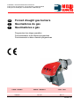
Installation, use and maintenance instructions
Instrucciones de Instalación, Funcionamiento y Mantenimiento
Instruções de Instalação, Funcionamento e Manutenção
GB
E
P
Forced draught gas burners
Quemadores de gas
Queimadores a gás
Progressive two-stage operation
Funcionamiento a dos llamas progresivas
Funcionamento a duas chamas progressivas
CODE - CÓDIGO
MODEL - MODELO
TYPE - TIPO
3785814
RS 190
835 T1
2916007 (2)
GB
CONTENTS
TECHNICAL DATA . . . . . . . . . . . . . . . . . . . . . . . . . . . . . . page
Accessories . . . . . . . . . . . . . . . . . . . . . . . . . . . . . . . . . . . . . . . . .
Burner description . . . . . . . . . . . . . . . . . . . . . . . . . . . . . . . . . . . .
Packaging - Weight . . . . . . . . . . . . . . . . . . . . . . . . . . . . . . . . . . .
Max. dimensions . . . . . . . . . . . . . . . . . . . . . . . . . . . . . . . . . . . . .
Standard equipment . . . . . . . . . . . . . . . . . . . . . . . . . . . . . . . . . . .
Firing rates . . . . . . . . . . . . . . . . . . . . . . . . . . . . . . . . . . . . . . . . . .
Test boiler. . . . . . . . . . . . . . . . . . . . . . . . . . . . . . . . . . . . . . . . . . .
Commercial boilers. . . . . . . . . . . . . . . . . . . . . . . . . . . . . . . . . . . .
Gas pressure . . . . . . . . . . . . . . . . . . . . . . . . . . . . . . . . . . . . . . . .
2
2
3
3
3
3
4
4
4
5
INSTALLATION . . . . . . . . . . . . . . . . . . . . . . . . . . . . . . . . . . . . . . 6
Boiler plate . . . . . . . . . . . . . . . . . . . . . . . . . . . . . . . . . . . . . . . . . . 6
Blast tube length . . . . . . . . . . . . . . . . . . . . . . . . . . . . . . . . . . . . . 6
Securing the burner to the boiler . . . . . . . . . . . . . . . . . . . . . . . . . 6
Setting the combustion head . . . . . . . . . . . . . . . . . . . . . . . . . . . . 7
Gas line . . . . . . . . . . . . . . . . . . . . . . . . . . . . . . . . . . . . . . . . . . . . 8
Electrical system . . . . . . . . . . . . . . . . . . . . . . . . . . . . . . . . . . . . . 9
Adjustments before firing . . . . . . . . . . . . . . . . . . . . . . . . . . . . . . 12
Servomotor. . . . . . . . . . . . . . . . . . . . . . . . . . . . . . . . . . . . . . . . . 12
Burner starting . . . . . . . . . . . . . . . . . . . . . . . . . . . . . . . . . . . . . . 12
Burner firing . . . . . . . . . . . . . . . . . . . . . . . . . . . . . . . . . . . . . . . . 12
Burner calibration: . . . . . . . . . . . . . . . . . . . . . . . . . . . . . . . . . . . 13
1 - Firing output . . . . . . . . . . . . . . . . . . . . . . . . . . . . . . . . . . . . . 13
2 - 2nd stage output . . . . . . . . . . . . . . . . . . . . . . . . . . . . . . . . . . 13
3 - 1st stage output. . . . . . . . . . . . . . . . . . . . . . . . . . . . . . . . . . . 14
4 - Intermediates outputs . . . . . . . . . . . . . . . . . . . . . . . . . . . . . . 14
5 - Air pressure switch . . . . . . . . . . . . . . . . . . . . . . . . . . . . . . . . 15
6 - Minimum gas pressure switch. . . . . . . . . . . . . . . . . . . . . . . . 15
Flame present check . . . . . . . . . . . . . . . . . . . . . . . . . . . . . . . . . 15
Burner operation. . . . . . . . . . . . . . . . . . . . . . . . . . . . . . . . . . . . . 16
Final checks . . . . . . . . . . . . . . . . . . . . . . . . . . . . . . . . . . . . . . . . 17
Maintenance. . . . . . . . . . . . . . . . . . . . . . . . . . . . . . . . . . . . . . . . 17
Burner start-up cycle diagnostics . . . . . . . . . . . . . . . . . . . . . . . 18
Resetting the control box and using diagnostics. . . . . . . . . . . 18
Fault - Probable cause - Suggested remedy . . . . . . . . . . . . . . . 19
Status (optional) . . . . . . . . . . . . . . . . . . . . . . . . . . . . . . . . . . . . . 20
N.B.
Figures mentioned in the text are identified as follows:
1)(A)
= part 1 of figure A, same page as text;
1)(A)p.3 = part 1 of figure A, page number 3.
1
TECHNICAL DATA
MODEL
RS 190
TYP
835 T1
2nd stage
OUTPUT (1)
kW
1279 - 2290
1100 - 1970
Mcal/h
min. 1st stage
kW
470
405
Mcal/h
FUEL
NATURAL GAS: G20 - G21 - G22 - G23 - G25
G20
G25
- net calorific value
kWh/Nm3
Mcal/Nm3
10
8.6
8.6
7.4
- absolute density
kg/Nm3
0.71
0.78
230
267
15
22
3
- max. delivery
Nm /h
- pressure at max. delivery
mbar
OPERATION
• On-Off (1 stop min each 24 hours).
• Two-stage (high and low flame) and single stage (all - nothing)
STANDARD APPLICATIONS
Boilers: water, steam, diathermic oil
AMBIENT TEMPERATUR
°C
COMBUSTION AIR TEMPERATURE
0 - 40
°C max 60
ELECTRICAL SUPPLY
V
Hz
ELECTRIC MOTOR
rpm
W
V
230 - 400 with neutral ~ +/-10%
50 - three-phaes
2800
4500
220/240 - 380/415
Running current
A
15.8 - 9.1
Start-up current
A
126 - 72.8
IGNITION TRANSFORMER
V1 - V2
I1 - I2
230 V - 1 x 8 kV
1 A - 20 mA
ELECTRICAL POWER CONSUMPTION
W max
ELECTRICAL PROTECTION
5500
IP 44
IN CONFORMITY WITH EEC DIRECTIVES
90/396 - 89/336 - 73/23
NOISE LEVELS (2)
dBA
83.1
APPROVAL
CE
0085AT0042
(1) Reference conditions: Ambient temperature 20°C - Barometric pressure 1000 mbar - Altitude 100 m a.s.l.
(2) Pressure at test point 17)(A)p.3, with zero pressure in the combustion chambre, with open gas ring 2)(B)p.7 an maximum burner output
(3) Sound pressure measured in manufacturers combustion laboratory, with burner operating on test boiler and at maximum rated output.
GAS CATEGORY
COUNTRY
CATEGORY
IT - AT - GR - DK - FI - SE
II2H3B / P
ES - GB - IE - PT
II2H3P
NL
II2L3B / P
FR
II2Er3P
DE
II2ELL3B /P
BE
I2E(R)B, I3P
LU
II2E 3B/P
ACCESSORIES (optional):
• KIT FOR LPG OPERATION: The kit allows the RS 190 burners to operate on LPG.
BURNER
OUTPUT
RS 190
kW
CODE
465 … 2290
3010166
• VIBRATION REDUCTION KIT: cod. 3010375
• STATUS (see page 20): code 3010322
• GAS TRAIN ACCORDING TO REGULATION EN 676 (with valves, pressure governor and filter): see page 8.
Important:
The installer is responsible for the addition of any safety device not forseen in the present manual.
2
(A)
D3144
mm
RS 190
BURNER DESCRIPTION (A)
1 Combustion head
2 Ignition electrode
3 Screw for combustion head adjustment
4 Sleeve
5 Servomotor controlling the gas butterfly
valve and of air gate valve (by means of a
variable profile cam mechanism).
When the burner is stopped the air gate
valve will be completely closed to reduce
heat loss due to the flue draught, which
tends to draw air from the fan air inlet.
6 Plug-socket on ionisation probe cable
7 Extension for slide bars 16)
8 Motor contactor and thermal cut-out reset
button
9 Flame stability disk
10 Terminal strip
11 Fairleads for electrical connections by installer
12 Two switches:
- one ≈burner off-on∆
- one for ≈1st - 2nd stage operation∆
13 Control box with lock-out pilot light and lockout reset button
14 Flame inspection window
15 Minimum air pressure switch
(differential operating type)
16 Slide bars for opening the burner and
inspecting the combustion head
17 Gas pressure test point and head fixing screw
18 Air pressure test point
19 Flame sensor probe
20 Air gate valve
21 Air inlet to fan
22 Screws securing fan to sleeve
23 Gas input pipework
24 Gas butterfly valve
25 Boiler mounting flange
26 Socket for electrical connections
A
B
C
kg
1250
725
785
82
Two types of burner failure may occur:
• Control box lock-out: if the control box
13)(A) pushbutton (red led) lights up, it indicates that the burner is in lock-out.
To reset, hold the pushbutton down for
between 1 and 3 seconds.
• Motor trip: release by pressing the pushbutton on thermal cutout 8)(A).
PACKAGING - WEIGHT (B)
Approximate measurements
• The burner stands on a wooden base which
can be lifted by fork-lifts.
Outer dimensions of packaging are indicated
in (B).
• The weight of the burner complete with packaging is indicated in Table (B).
(B)
D36
MAX. DIMENSIONS (C)
Approximate measurements
The maximum dimensions of the burner are
given in (C).
Bear in mind that inspection of the combustion
head requires the burner to be opened by withdrawing the rear part on the slide bars.
The maximum dimension of the burner when
open is give by measurement I.
D1261
mm
RS 190
A
B
C
D
E
F
G
H
I
L
M
N
O
681 366 315 555 856 372 222 430 1312 230 150 186 DN80
(C)
3
STANDARD EQUIPMENT
1 - Gas train flange
1 - Flange gasket
4 - Flange fixing screws M 10 x 35
1 - Thermal insulation screen
4 - Screws to secure the burner flange to the
boiler: M 12 x 35
3 - Plugs for electrical connections
1 - Instruction booklet
1 - Spare parts list
FIRING RATES (A)
The RS 190 model burner can work in two way:
one-stage and two-stage.
MAXIMUM OUTPUT must be selected in area
A.
pressure mbar
Combustion chamber
RS 190
MINIMUM OUTPUT must not be lower than the
minimum limit shown in the diagram.
RS 190
Important
The FIRING RATE value range has been
obtained considering an ambient temperature of
20 °C, and an atmospheric pressure of 1000
mbar (approx. 100 m above sea level) and with
the combustion head adjusted as shown on
page 7.
(A)
D1262
length m
Combustion chamber
= 470 kW
(B)
D715
4
TEST BOILER (B)
The firing rates were set in relation to special
test boilers, according to EN 676 regulations.
Figure (B) indicates the diameter and length of
the test combustion chamber.
Example:
Output 756 kW:
diameter = 60 cm; length = 2 m.
COMMERCIAL BOILERS
The burner/boiler combination does not pose
any problems if the boiler is CE type-approved
and its combustion chamber dimensions are
similar to those indicated in diagram (B).
If the burner must be combined with a commercial boiler that has not been CE type-approved
and/or its combustion chamber dimensions are
clearly smaller than those indicated in diagram
(B), consult the manufacturer.
GAS PRESSURE
The adjacent table shows minimum pressure
losses along the gas supply line depending on
the burner output in 2nd stage operation.
∆p (mbar)
RS 190
3
kW
1
2
3970146
3970160
3970181
3970182
3970147
3970161
3970148
3970162
3970149
3970163
1280
7,0
1,8
30,0
25,0
11,0
5,6
-
1400
7,3
2,0
35,0
29,0
15,0
7,0
-
1500
7,6
2,2
40,0
32,0
16,0
8,0
-
1600
8,0
2,5
45,0
35,0
17,0
9,0
4,5
1700
8,7
2,8
52,0
38,5
19,0
10,0
4,7
1800
9,3
3,0
58,0
42,0
21,0
11,0
5,0
1900
10,2
3,2
63,0
46,0
23,0
12,0
5,8
2000
11,3
3,4
68,0
50,0
25,0
13,0
6,1
2100
12,5
3,7
74,0
53,0
27,5
14,0
6,8
2290
15,0
4,3
88,0
60,0
34,0
17,0
8,0
Column 1
Pressure loss at combustion head.
Gas pressure measured at test point 1)(B), with:
• Combustion chamber at 0 mbar
• Burner operating in 2nd stage
• Combustion head adjusted as indicated in
diagram (C)p. 7.
Column 2
Pressure loss at gas butterfly valve 2)(B) with
maximum opening: 90°.
Column 3
Pressure loss of gas train 3)(B) includes: adjustment valve VR, safety valve VS (both fully
open), pressure governor R, filter F.
The values shown in the various tables refer to:
natural gas G20 PCI 10 kWh/Nm3 (8.6 Mcal/Nm3).
With:
(A)
natural gas G25 PCI 8.6 kWh/Nm3 (7.4 Mcal/Nm3)
multiply tabulated values by 1.3.
Calculate the approximate 2nd stage output of
the burner thus:
- Subtract the combustion chamber pressure
from the gas pressure measured at test point
1)(B).
- Find the nearest pressure value to your result
in column 1 of the table (A).
- Read off the corresponding output on the left.
Example:
• 2nd stage operation
• Natural gas G20 PCI 10 kWh/Nm3
• Gas pressure at test point 1)(B)
= 11 mbar
• Pressure in combustion chamber = 3 mbar
11 - 3= 8 mbar
A 2nd stage output of 1600 kW shown in Table
(A) corresponds to 8 mbar pressure, column 1.
This value serves as a rough guide, the effective
delivery must be measured at the gas meter.
D1263
(B)
To calculate the required gas pressure at test
point 1)(B), set the output required from the
burner in 2nd stage operation:
- Find the nearest output value in the table (A).
- Read off the pressure at test point 1)(B) on
the right in column 1.
- Add this value to the estimated pressure in
the combustion chamber.
Example:
• Required burner output in 2nd stage operation: 1600 kW
• Natural gas G20 PCI 10 kWh/Nm3
• Gas pressure at burner output of 1600 kW,
taken from table (A), column 1
= 8 mbar
• Pressure in combustion chamber = 3 mbar
8 + 3 = 11 mbar
pressure required at test point 1)(B).
5
INSTALLATION
mm
RS 190
A
B
C
230
325-368
M 16
BOILER PLATE (A)
Drill the combustion chamber locking plate as
shown in (A). The position of the threaded holes
can be marked using the thermal screen supplied with the burner.
(A)
D455
BLAST TUBE LENGTH (B)
The length of the blast tube must be selected
according to the indications provided by the
manufacturer of the boiler, and in any case it
must be greater than the thickness of the boiler
door complete with its fettling. The length available, L (mm), is 372 mm.
For boilers with front flue passes 15) or flame
inversion chambers, protective fettling in refractory material 13) must be inserted between the
boiler fettling 14) and the blast tube 12).
This protective fettling must not compromise the
extraction of the blast tube.
For boilers having a water-cooled front the
refractory fettling 13)-14)(B) is not required
unless it is expressly requested by the boiler
manufacturer.
SECURING THE BURNER TO THE BOILER
(B)
Before securing the burner to the boiler, check
through the blast tube opening to make sure
that the flame sensor probe and the ignition
electrode are correctly set in position, as shown
in (C).
(B)
D3036
Probe
Electrode
Now detach the combustion head from the
burner, fig.(B):
- Loosen the 4 screws 3) and remove the cover 1)
- Disengage the articulated coupling 7) from
the graduated sector 8).
- Remove the screws 2) from the slide bars 5).
- Remove the two screws 4) and pull the burner
back on slide bars 5) by about 100 mm.
Disconnect the wires from the probe and the
electrode and then pull the burner completely
off the slide bars.
Secure the flange 11)(B) to the boiler plate, interposing the thermal insulating screen 9)(B) supplied with the burner. Use the 4 screws, also
supplied with the unit, after first protecting the
thread with an anti-locking product.
The seal between burner and boiler must be airtight.
(C)
D1265
(D)
D1266
6
If you noticed any irregularities in positions of
the probe or ignition electrode during the check
mentioned above, remove screw 1)(D), extract
the internal part 2)(D) of the head and proceed
to set up the two components correctly.
Do not attempt to turn the probe. Leave it in the
position shown in (C) since if it is located too
close to the ignition electrode the control box
amplifier may be damaged.
SETTING THE COMBUSTION HEAD
Installation operations are now at the stage
where the blast tube and sleeve are secured to
the boiler as shown in fig. (B). It is now a very
simple matter to set up the combustion head, as
this depends solely on the output developed by
the burner in 2nd stage operation.
It is therefore essential to establish this value
before proceeding to set up the combustion
head.
There are two adjustments to make on the
head.
Air adjustment (B) See diagram (C).
Turn screw 4)(B) until the notch identified is
aligned with the front surface 5)(B) of the flange.
D1267
(A)
(B)
Nr. Notches
Gas adjustment (A)
When the burner is installed for an output in 2nd
stage ≤ 1300 Mcal/h (about 1500 kW) assemble
the supplied disks 1)-2)(A) removing the inner
pipe 3)(A). If there is little gas in the network, the
head may be left in standard configuration, limiting the minimum modulation to 450 Mcal/h
(circa 520 kW).
Example
Burner output = 1593 kW (1370 Mcal/h).
If we consult diagram (C) we find that for this
output, air must be adjusted using notch 3, as
shown in fig. (B).
Continuing with the previous example, page 5
indicates that for burner with output of 1593 kW
(1370 Mcal/h) a pressure of approximately 8
mbar is necessary at test point 6)(B).
(C)
Burner output in 2nd stage operation
D1268
Once you have finished setting up the head, refit
the burner to the slide bars 3)(D) at approximately 100 mm from the sleeve 4)(D) - burner
positioned as shown in fig. (B)p. 6 - insert the
flame detection probe cable and the ignition
electrode cable and then slide the burner up to
the sleeve so that it is positioned as shown in
fig. (D).
Refit screws 2) on slide bars 3).
Secure the burner to the sleeve by tightening
screw 1).
Reconnect the articulation 7) to the graduated
sector 6).
Important
When fitting the burner on the two slide bars, it
is advisable to gently draw out the high tension
cable and flame detection probe cable until they
are slightly stretched.
(D)
D3037
7
GAS LINE
• The gas train can enter the burner from the
right or left side, depending on which is the
most convenient.
• Gas solenoids 8)-9)(A) must be as close as
possible to the burner to ensure gas reaches
the combustion head within the safety time
range of 3 s.
• Make sure that the pressure governor calibration range (colour of the spring) comprises the
pressure required by the burner.
GAS TRAIN (A)
It is type-approved according to EN 676 Standards and is supplied separately from the burner
with the code indicated in Table (B).
(A)
D1270
BURNERS AND RELEVANT GAS TRAINS APPROVED ACCORDING TO EN 676
Gas train L
13
14
Æ
C.T.
Code
Code
Code
2∆
-
3970146
3010123
3010128
2∆
♦
3970160
-
3010128
2∆
-
3970181
3010123
3010128
2∆
♦
3970182
-
3010128
DN 65
-
3970147
3010123
3000831
DN 65
♦
3970161
-
3000831
DN 80
-
3970148
3010123
3000832
DN 80
♦
3970162
-
3000832
DN 100
-
3970149
3010123
3010127
DN 100
♦
3970163
-
3010127
P1 - Pressure at combustion head
P2 - Pressure down-line from the pressure governor
P3 - Pressure up-line from the filter
(B)
GAS TRAINS COMPONENTS L
L - Gas train supplied separately with the code
indicated in Table (B)
L1 - The responsibility of the installer
Components
Code
3970146
3970160
Filter
5
Pressure governor
6
Valves
8-9
GF 520/1
FRS 520
DMV-DLE 520/11
3970181
3970182
KEY (A)
1 - Gas input pipe
2 - Manual valve
3 - Vibration damping joint
4 - Pressure gauge with pushbutton cock
5 - Filter
6 - Pressure governor
(vertical)
7 - Minimum gas pressure switch
8 - Safety solenoid
VS
(vertical)
9 - Adjustment solenoid
VR (vertical)
Two adjustments:
• ignition delivery
(rapid opening)
• maximum delivery
(slow opening)
10 - Standard issue burner gasket
11 - Gas adjustment butterfly valve (DN 80)
12 - Burner
13 - Gas valve 8)-9) leak detection control
device.
In accordance with EN 676 Standards, gas
valve leak detection control devices are
compulsory for burners with maximum outputs of more than 1200 kW; therefore only
for model RS 130.
14 - Gas train/burner adaptor.
Multiblock MB DLE 420
3970147
3970161
GF 40065/3
FRS 5065
DMV-DLE 5065/11
3970148
3970162
GF 40080/3
FRS 5080
DMV-DLE 5080/11
3970149
3970163
GF40100/3
FRS 5100
DMV-DLE 5100/11
KEY TO TABLE (B)
C.T.=Gas valves 8) - 9) leak detection control
devices:
- = Gas train without gas valve leak detection control device; device that can be
ordered separately and assembled subsequently (see Column 13).
♦= Gas train with assembled VPS valve
leak detection control device.
13 = VPS valve leak detection control device.
Supplied separately from gas train on
request.
14 = Gas train/burner adaptor.
Supplied separately from gas train on
request.
Note
See the accompanying instructions for the
adjustment of the gas train.
8
ELECTRICAL SYSTEM
ELECTRICAL EQUIPMENT FACTORY-SET
RS 190
ELECTRICAL SYSTEM as set up by the manufacturer
LAYOUT (A)
Burner RS 190
• Models RS 190 leaves the factory preset for
400 V power supply.
• If 230 V power supply is used, change the
motor connection from star to delta and
change the setting of the thermal cut-out as
well.
RMG88.62A2
(A)
D3145
Key to Layout (A)
CMV
- Motor contactor
DA
- Control box (Landis RMG)
F1
- Protection against radio interference
K1
- Relay
I1
- Switch: burner off - on
I2
- Switch: 1st - 2nd stage operation
MB
- Burner terminal strip
MV
- Fan motor
PA
- Air pressure switch
RT
- Thermal cut-out
SM
- Servomotor
SO
- Ionisation probe
SP
- Plug-socket
TA
- Ignition transformer
TB
- Burner ground
XP1
- Connector for STATUS
XP4
- 4 pole socket
XP6
- 6 pole socket
XP7
- 7 pole socket
ATTENTION
In the case of phase-phase feed, a bridge
must be fitted on the control box terminal strip
between terminal 6 and the earth terminal.
9
ELECTRICAL CONNECTIONS
Use flexible cables according to EN 60 335-1
Regulations:
• if in PVC sheath, use at least H05 VV-F
• if in rubber sheath, use at least H05 RR-F.
All the wires to connect to the burner terminal
strip 9)(A) must enter through the supplied fairleads.
The fairleads and hole press-outs can be used
in various ways; the following lists show one
possible solution:
(A)
D955
RS 190 without leak detection control device
1 - Pg 13,5 Three-phase power supply
2 - Pg 11 Socket XP6 - gas valves
3 - Pg 11 Socket XP7 - remote control device
TL and single-phase power supply
4 - Pg 9
Socket XP4 - remote control device
TR
5 - Pg 13,5 Not utilized
6 - Pg 13,5 Gas pressure switch or gas valve
leak detection control device
7 - Pg 11 Open the hole, if a pipe union is to
be added
8 - Pg 9
Open the hole, if a pipe union is to
be added
LAYOUT (B)
Electrical connection RS 190 burners without leak detection control device.
LAYOUT (C)
Electrical connection RS 190 burners with
VPS leak detection control device.
Gas valve leak detection control takes place
immediately before every burner start-up.
(B)
D3141
RS 190 with leak detection control device VPS
(C)
D3142
RS 190
230 V 400 V
F
A
T25
T25
L
mm2
2,5
2,5
(D)
10
Fuses and cables cross-section layouts (B) and
(C), see table (D).
Cross-section when not indicated: 1,5 mm2.
KEY TO LAYOUTS (B - C)
h1 - 1st stage hourcounter
h2 - 2nd stage hourcounter
IN - Burner manual stop switch
X4 - 4 pole plug
X6 - 6 pole plug
X7 - 7 pole plug
XP- Plug for leak detection control device
MB- Burner terminal strip
PG- Min. gas pressure switch
S - Remote lock-out signal
S1 - Remote lock-out signal of leak detection
control device
TR- High-low mode load remote control system:
controls operating stages 1 and 2.
If the burner is to be set up for single stage
operation, replace of remote control device
TR with a jumper.
TL - Load limit remote control system:
shuts down the burner when the boiler temperature or pressure reaches the preset
value.
TS - Safety load control system:
operates when TL is faulty
VR- Adjustment valve
VS- Safety valve
LAYOUT (A)
Calibration of thermal cut-out 8)(A)p. 3
This is required to avoid motor burn-out in the
event of a significant increase in power absorption caused by a missing phase.
• If the motor is star-powered, 400 V, the cursor
should be positioned to "MIN".
• If the motor is delta-powered, 230 V, the cursor should be positioned to "MAX".
Even if the scale of the thermal cut-out does not
include rated motor absorption at 400 V, protection is still ensured in any case.
CALIBRATION OF THERMAL RELAY
(A)
D867
N.B.
Burner RS 190 leaves the factory preset for 400
V power supply. If 230 V power supply is used,
change the motor connection from star to delta
and change the setting of the thermal cutout as
well.
The RS 190 burner has been type- approved for
intermittent operation. This means it shoulds
compulsorily be stopped at least once every 24
hours to enable the control box to perform
checks of its own efficiency at start-up. Burner
halts are normally provided for automatically by
the boiler load control system.
If this is not the case, a time switch should be fitted in series to IN to provide for burner shutdown at least once every 24 hours.
The RS 190 burner is factory set for two-stage
operation and must therefore be connected to
control device TR.
Alternatively, if single stage operation is
required, instead of control device TR install a
jumper lead between terminals 6 and 7 of the
terminal strip.
WARNING: Do not invert the neutral with
the phase wire in the electricity supply
line. Inverting the wires will make the
burner go into lock-out because of firing
failure.
11
MIN GAS PRESSURE SWITCH
AIR PRESSURE SWITCH
(A)
(B)
D897
ADJUSTMENTS BEFORE FIRST FIRING
Adjustment of the combustion head, and air and
gas deliveries has been illustrated on page 7.
In addition, the following adjustments must also
be made:
- open manual valves up-line from the gas
train.
- Adjust the minimum gas pressure switch to
the start of the scale (A).
- Adjust the air pressure switch to the zero
position of the scale (B).
- Purge the air from the gas line.
Continue to purge the air (we recommend
using a plastic tube routed outside the building) until gas is smelt.
- Fit a U-type manometer (C) to the gas pressure test point on the sleeve.
The manometer readings are used to calculate the 2nd stage operation burner power
using the tables on page 5.
- Connect two lamps or testers to the two gas
line solenoid valves VR and VS to check the
exact moment at which voltage is supplied.
This operation is unnecessary if each of the
two solenoid valves is equipped with a pilot
light that signals voltage passing through.
Before starting up the burner it is good practice
to adjust the gas train so that ignition takes
place in conditions of maximum safety, i.e. with
gas delivery at the minimum.
SERVOMOTOR (D)
The servomotor provides simultaneous adjustment of the air gate valve, by means of the variable profile cam, and the gas butterfly valve.
The servomotor rotates through 130 degrees in
15 seconds.
Do not alter the factory setting for the 4 levers;
simply check that they are set as indicated
below:
(C)
D3038
SERVOMOTOR
(D)
D1272
1
2
Burner off
1st stage
Burner on
2nd stage
(E)
D469
12
Cam I
: 130°
Limits rotation toward maximum position.
When the burner is in 2nd stage operation the
gas butterfly valve must be fully open: 90°.
Cam II
: 0°
Limits rotation toward the minimum position.
When the burner is shut down the air gate valve
and the gas butterfly valve must be closed: 0°.
Cam III
: 15°
Adjusts the ignition position and the output in 1st
stage operation.
Cam V
: 125°
Lights up the 2nd stage LED (STATUS)
BURNER STARTING
Close the control devices and set:
• switch 1)(E) to "Burner ON" position;
• switch 2)(E) to "1st STAGE" position.
As soon as the burner starts check the direction
of rotation of the fan blade, looking through the
flame inspection window 14)(A)p.3.
Make sure that the lamps or testers connected
to the solenoids, or pilot lights on the solenoids
themselves, indicate that no voltage is present.
If voltage is present, then immediately stop the
burner and check electrical connections.
BURNER FIRING
Having completed the checks indicated in the
previous heading, the burner should fire. If the
motor starts but the flame does not appear and
the control box goes into lock-out, reset and wait
for a new firing attempt.
If firing is still not achieved, it may be that gas is
not reaching the combustion head within the
safety time period of 3 seconds.
In this case increase gas firing delivery.
The arrival of gas at the sleeve is indicated by
the U-type manometer (C).
Once the burner has fired, now proceed with
global calibration operations.
BURNER CALIBRATION
The optimum calibration of the burner requires
an analysis of the flue gases at the boiler outlet.
1
Adjust successively:
1 - First firing output
2 - 2nd stage burner output
3 - 1st stage burner output
4 - Intermediate outputs between 1st and 2nd stage
5 - Air pressure switch
6 - Minimum gas pressure switch
2
Burner off
1st stage
Burner on
2nd stage
1 - FIRING OUTPUT
According to EN 676 Regulations:
(A)
D469
Burners with max. output up to 120 kW
Firing can be performed at the maximum operation output level. Example:
• Max. operation output
: 120 kW
• Max. firing output
: 120 kW
Burners with max. output above 120 kW
Firing must be performed at a lower output than
the max. operation output. If the firing output
does not exceed 120 kW, no calculations are
required. If firing output exceeds 120 kW, the
regulations prescribe that the value be defined
according to the control box safety time "ts":
• for "ts" = 2s, firing output must be equal to or
lower than 1/2 of max. operation output.
• For "ts" = 3s, firing output must be equal to or
lower than 1/3 of max. operation output.
Example: MAX operation output of 600 kW.
Firing output must be equal to or lower than:
• 300 kW with "ts" = 2s
• 200 kW with "ts" = 3s
In order to measure the firing output:
- disconnect the plug-socket 6)(A)p.3 on the
ionization probe cable (the burner will fire and
then go into lock-out after the safety time has
elapsed).
- Perform 10 firings with consecutive lock-outs.
- On the meter read the quantity of gas burned.
This quantity must be equal to or lower than
the quantity given by the formula, for ts = 3s:
Nm3/h (max. burner delivery)
360
Example: for G 20 gas (10 kWh/Nm3):
Max. operation output: 600 kW corresponding to
60 Nm3/h.
After 10 firings with lock-outs, the delivery read
on the meter must be equal to or lower than:
60 : 360 = 0,166 Nm3.
2 - 2ND STAGE OUTPUT
2nd stage output of the burner must be set
within the firing rate range shown on page 4.
In the above instructions we left the burner running in 1st stage operation. Now set switch 2)(A)
to the 2nd stage position: the servomotor will
open, simultaneously, the air gate valve and the
gas butterfly valve to 90°.
Gas calibration
Measure the gas delivery at the meter.
A guideline indication can be calculated from the
tables on page 5, simply read off the gas pressure on the U-type manometer, see fig.(C) on
page 12, and follow the instructions on page 5.
- If delivery needs to be reduced, diminish outlet gas pressure and, if it is already very low,
slightly close adjustment valve VR.
- If delivery needs to be increased, increase
outlet gas pressure.
13
Adjusting air delivery
Progressively adjust the end profile of cam 4)(A)
by turning the screws 7).
- Turn the screws clockwise to increase air
delivery.
- Turn the screws counter-clockwise to reduce
air delivery.
3 - 1ST STAGE OUTPUT
Burner power in 1st stage operation must be
selected within the firing rate range shown on
page 4.
Set the switch 2)(A)p.13 to the 1st stage position: the servomotor 1)(A) will close the air gate
valve and, at the same time, closes the gas butterfly valve down to 15°, i.e. down to the original
factory setting.
Adjusting gas delivery
Measure the delivery of gas from the gas meter.
- If this value is to be reduced, decrease the
angle of the orange lever (B) slightly by proceeding a little at a time until the angle is
changed from 15° to 13° or 11°....
- If it is necessary to increase the mains pressure, move to 2nd stage operation by altering
the setting of switch 2)(A)p.13 and increase
the angle of the orange lever, proceeding a little at a time until the angle is changed from
15° to 17° - 19°....
At this point return to 1st stage operation and
measure gas delivery.
D891
(A)
Note
The servomotor follows the adjustment of the
orange lever only when the angle is reduced.
If, however the angle must be increased, switch
to 2nd stage operation, increase the angle and
then return to 1st stage operation to check the
effect of the adjustment.
In order to adjust cam III, especially for fine
movements, the key 10)(B), held by a magnet
under the servomotor, can be used.
Adjustment of air delivery
Progressively adjust the starting profile of cam
4)(A) by turning the screws 5). It is preferable
not to turn the first screw since this is used to set
the air gate valve to its fully-closed position.
4 - INTERMEDIATE OUTPUTS
Adjustment of gas delivery
No adjustment of gas delivery is required.
D889
(B)
1
2
3
4
5
6
7
8
Servomotor
Servomotor 1) - Cam 4): engaged
Servomotor 1) - Cam 4): disengaged
Adjustable profile cam
Cam starting profile adjustment screws
Adjustment fixing screws
Cam end profile adjustment screws
Graduated sector for gas butterfly
valve
9 Index for graduated sector 8
10 Key for cam III adjustment
Adjustment of air delivery
Switch off the burner using switch 1)(A)p.13,
disengage the cam 4)(A) from the servomotor,
by pressing the button 3)(B) and moving it to the
right, and check more than once that the movement is soft and smooth, and does not grip, by
rotating the cam 4) forward and backward by
hand.
Engage the cam 4) to the servomotor again by
moving the button 2)(B) to the left.
As far as is possible, try not to move those
screws at the ends of the cam that were previously adjusted for 1st and 2nd stage air gate
valve control.
Finally fix the adjustment by turning the screws
6)(A).
Note
Once you have finished adjusting outputs 2ND
STAGE - 1ST STAGE - INTERMEDIATE, check
ignition once again: noise emission at this stage
must be identical to the following stage of operation.
If you notice any sign of pulsations, reduce the
ignition stage delivery.
14
5 - AIR PRESSURE SWITCH (A)
Adjust the air pressure switch after having performed all other burner adjustments with the air
pressure switch set to the start of the scale (A).
With the burner operating in 1st stage, increase
adjustment pressure by slowly turning the relative knob clockwise until the burner locks out.
Then turn the knob anti-clockwise by about 20%
of the set point and repeat burner starting to
ensure it is correct.
If the burner locks out again, turn the knob anticlockwise a little bit more.
AIR PRESSURE SWITCH 15)(A)p. 3
Attention
As a rule, the air pressure switch must limit the
CO in the fumes to less than 1% (10,000 ppm).
To check this, insert a combustion analyser into
the chimney, slowly close the fan suction inlet
(for example with cardboard) and check that the
burner locks out, before the CO in the fumes
exceeds 1%.
(A)
D521
MIN GAS PRESSURE SWITCH 7)(B)p. 8
The air pressure switch may operate in "differential" operation in two pipe system. If a negative pressure in the combustion chamber during
pre-purging prevents the air pressure switch
from switching, switching may be obtained by fitting a second pipe between the air pressure
switch and the suction inlet of the fan. In such a
manner the air pressure switch operates as differenzial pressure switch.
Warning
The use of the air pressure switch with differential operation is allowed only in industrial applications and where rules enable the air pressure
switch to control only fan operation without any
reference to CO limit.
(B)
D896
(C)
D3023
15
6 - MINIMUM GAS PRESSURE SWITCH (B)
Adjust the minimum gas pressure switch after
having performed all the other burner adjustments with the pressure switch set at the start of
the scale (B).
With the burner operating in 2nd stage, increase
adjustment pressure by slowly turning the relative knob clockwise until the burner locks out.
Then turn the knob anti-clockwise by 2 mbar
and repeat burner starting to ensure it is uniform.
If the burner locks out again, turn the knob anticlockwise again by 1 mbar.
FLAME PRESENT CHECK (C)
The burner is fitted with an ionisation system
which ensures that a flame is present. The minimum current for plant operation is 5 ±A.
The burner provides a much higher current, so
that controls are not normally required. However, if it is necessary to measure the ionisation
current, disconnect the plug-socket 6)(A)p.3 on
the ionisation probe cable and insert a direct
current microamperometer with a base scale of
100 ±A.
Carefully check polarities!
BURNER OPERATION
NORMAL FIRING
(n° = seconds from instant 0)
BURNER STARTING (A)
•
•
•
•
0s
2s
3s
• 28 s
• 43 s
• 45 s
• 53 s
RMG
LED *
*
Off
Yellow
Green
Red
For further details see page 18.
(A)
D3051
NO FIRING
RMG
LED *
*
Off
Yellow
: Control device TL closes.
Servomotor starts: it rotates during
opening up to the angle set on cam
with orange lever.
After about 3s:
: The control box starting cycle begins.
: Fan motor starts.
: Servomotor starts: it rotates during
opening until contact is made on cam
with red lever.
The air gate valve is positioned to 2nd
stage output.
Pre-purge stage with air delivery at
2nd stage output.
Duration 25 seconds.
: Servomotor starts: it rotates during
closing up to the angle set on cam
with orange lever.
: The air gate valve and the gas butterfly are positioned to 1st stage output.
Ignition electrode strikes a spark.
Safety valve VS and adjustment valve
VR (rapid opening) open. The flame
is ignited at a low output level, point
A. Output is then progressively
increased, with the valve opening
slowly up to 1st stage output, point B.
: The spark goes out.
: If remote control device TR is closed
or if it has been replaced by a jumper,
the servomotor will continue to turn
until the cam with red lever come into
operation, setting the air gate valve
and the gas butterfly valve to the 2nd
stage operation position, section C-D.
The control box starting cycle ends.
STEADY STATE OPERATION (A)
System equipped with one control device TR.
Once the starting cycle has come to an end,
control of the servomotor passes on to the control device TR that controls boiler temperature or
pressure, point D.
(The control box will continue, however, to monitor flame presence and the correct position of
the air pressure switch).
• When the temperature or the pressure
increases until the control device TR opens,
the servomotor closes the gas butterfly valve
and the air gate valve and the burner passes
from the 2nd to the 1st stage of operation,
section E-F.
• When the temperature or pressure decreases
until the control device TR closes, the servomotor opens the gas butterfly valve and the
air gate valve and the burner passes from the
1st to the 2nd stage of operation, and so on.
• The burner stops when the demand for heat
is less than the amount of heat delivered by
the burner in the 1st stage, section G-H. Control device TL now opens, the servomotor
returns toward the 0° position, limited in this
movement by cam with blue lever. The air
gate valve closes completely to reduce heat
losses to a minimum.
Systems not equipped with control device TR
(jumper wire installed)
The burner is fired as described in the case
above. If the temperature or pressure increase
until control device TL opens, the burner shuts
down (Section A-A in the diagram).
FIRING FAILURE (B)
If the burner does not fire, it goes into lock-out
within 3 s of the opening of the gas solenoid
valve and 49 s after the closing of control
device TL. The control box red pilot light will
light up.
Red
For further details see page 18.
(B)
D3052
16
BURNER FLAME GOES OUT DURING OPERATION
If the flame should accidentally go out during
operation, the burner will lock out within 1s.
FINAL CHECKS (with burner running)
• Disconnect one of the wires on the minimum
gas pressure switch:
• Open remote control device TL:
• Open remote control device TS:
the burner must stop
FLAME INSPECTION WINDOW
• Disconnect the common wire P from the air
pressure switch:
• Disconnect the ionisation probe lead:
the burner must lock out
• Make sure that the mechanical locking systems on the various adjustment devices are
fully tightened.
MAINTENANCE
(A)
D709
OPENING THE BURNER
Combustion
The optimum calibration of the burner requires
an analysis of the flue gases. Significant differences with respect to the previous measurements indicate the points where more care
should be exercised during maintenance.
Gas leaks
Make sure that there are no gas leaks on the
pipework between the gas meter and the burner.
Gas filter
Change the gas filter when it is dirty.
Flame inspection window
Clean the flame inspection window (A).
Combustion head
Open the burner and make sure that all components of the combustion head are in good condition, not deformed by the high temperatures,
free of impurities from the surroundings and correctly positioned. If in doubt, disassemble the
elbow fitting 5)(B).
Burner
Check for excess wear or loose screws in the
mechanisms controlling the air gate valve and
the gas butterfly valve. Also make sure that the
screws securing the electrical leads in the
burner terminal strip are fully tightened.
Clean the outside of the burner, taking special
care with the transmission joints and cam
4)(A)p.14.
(B)
D3041
Combustion
Adjust the burner if the combustion values found
at the beginning of the operation do not comply
with the regulations in force, or at any rate, do
not correspond to good combustion. Use the
appropriate card to record the new combustion
values; they will be useful for subsequent controls.
TO OPEN THE BURNER (B):
- switch off the electrical power.
- Loosen screws 1) and withdraw cover 2).
- Disengage the articulated coupling 7) from
the graduated sector 8).
- Fit the two standard supplied extensions onto
the slide bars 4).
- Remove screws 3), and pull the burner back
by about 100 mm on the slide bars 4). Disconnect the probe and electrode leads and then
pull the burner fully back.
Now extract the gas distributor 5) after having
removed the screw 6).
TO CLOSE THE BURNER (B):
- push the burner until it is about 100 mm from
the sleeve.
- Re-connect the leads and slide in the burner
until it comes to a stop.
- Refit screws 3), and pull the probe and electrode leads gently out until they are slightly
stretched.
- Re-couple the articulated coupling 7) to the
graduated sector 8).
- Remove the two extensions from the slide
bars 4).
17
BURNER START-UP CYCLE DIAGNOSTICS
During start-up, indication is according to the followin table:
COLOUR CODE TABLE
Sequences
Colour code
Pre-purging
Ignition phase
Operation, flame ok
Operating with weak flame signal
Electrical supply lower than ~ 170V
Lock-out
Extraneous light
Legenda:
Off
Yellow
Green
Red
RESETTING THE CONTROL BOX AND USING DIAGNOSTICS
The control box features a diagnostics function through which any causes of malfunctioning are easily identified (indicator: RED LED).
To use this function, you must wait at least 10 seconds once it has entered the safety condition (lock-out), and then press the reset button.
The control box generates a sequence of pulses (1 second apart), which is repeated at constant 3-second intervals.
Once you have seen how many times the light pulses and identified the possible cause, the system must be reset by holding the button
down for between 1 and 3 seconds.
RED LED on
wait at least 10s
Lock-out
Press reset
for > 3s
Pulses
Interval
3s
Pulses
The methods that can be used to reset the control box and use diagnostics are given below.
RESETTING THE CONTROL BOX
To reset the control box, proceed as follows:
- Hold the button down for between 1 and 3 seconds.
The burner restarts after a 2-second pause once the button is released.
If the burner does not restart, you must make sure the limit thermostat is closed.
VISUAL DIAGNOSTICS
Indicates the type of burner malfunction causing lock-out.
To view diagnostics, proceed as follows:
- Hold the button down for more than 3 seconds once the red LED (burner lock-out) remains steadily lit.
A yellow light pulses to tell you the operation is done.
Release the button once the light pulses. The number of times it pulses tells you the cause of the malfunction, according to the coding
system indicated in the table on page 19.
SOFTWARE DIAGNOSTICS
Reports burner life by means of an optical link with the PC, indicating hours of operation, number and type of lock-outs, serial number of
control box etc ...
To view diagnostics, proceed as follows:
- Hold the button down for more than 3 seconds once the red LED (burner lock-out) remains steadily lit.
A yellow light pulses to tell you the operation is done.
Release the button for 1 second and then press again for over 3 seconds until the yellow light pulses again.
Once the button is released, the red LED will flash intermittently with a higher frequency: only now can the optical link be activated.
Once the operations are done, the control box»s initial state must be restored using the resetting procedure described above.
BUTTON PRESSED FOR
CONTROL BOX STATUS
Between 1 and 3 seconds
Control box reset without viewing visual diagnostics.
More than 3 seconds
Visual diagnostics of lock-out condition:
(LED pulses at 1-second intervals).
More than 3 seconds starting from the visual
diagnostics condition
Software diagnostics by means of optical interface and PC (hours of operation, malfunctions etc. can be viewed)
The sequence of pulses issued by the control box identifies the possible types of malfunction, which are listed in the table on page 19.
18
SIGNAL
FAULT
PROBABLE CAUSE
2 x blinks
After pre-purge and
safety time, the burner
goes tolock-out and the
flame does not appear
1
2
3
4
5
6
7
8
9
10
11
12
13
-
3 x blinks
The burner does not start 14 - Air pressure switch in operating position
and lock-out warning
appears
The burner starts and
then locks out
15
16
17
18
-
SUGGESTED REMEDY
The solenoid VR allows little gas through . . . . . . . . . . . . . . Increase
Solenoid valves VR or VS fail to open . . . . . . . . . . . . . . . . Renew the coil or rectifier panel
Gas pressure too low . . . . . . . . . . . . . . . . . . . . . . . . . . . . . Increase pressure at governor
Ignition electrode wrongly adjusted . . . . . . . . . . . . . . . . . . . Adjust, see fig. (C)p. 6
Electrode grounded due to brocken insulation . . . . . . . . . . Replace
High voltage cable defective . . . . . . . . . . . . . . . . . . . . . . . . Replace
High voltage cable deformed by high temperature . . . . . . . Replace and protect
Ignition trasformer defective . . . . . . . . . . . . . . . . . . . . . . . . Replace
Erroneous valve or trasformer electrical connections . . . . . Check
Control box defective . . . . . . . . . . . . . . . . . . . . . . . . . . . . . Replace
A cock down-line of the gas train is closed . . . . . . . . . . . . . Open
Air in pipework. . . . . . . . . . . . . . . . . . . . . . . . . . . . . . . . . . . Bleed air
VS and VR gas valves unconnected or with interrupted coil . . Check connections or replace coil
Adjust or replace
Air pressure switch inoperative due to
insufficient air pressure:
Air pressure switch adjusted badly . . . . . . . . . . . . . . . . . . . Adjust or replace
Pressure switch pressure point pipe blocked . . . . . . . . . . . Clean
Head wrongly adjusted . . . . . . . . . . . . . . . . . . . . . . . . . . . . Adjust
High negative draft in chamber . . . . . . . . . . . . . . . . . . . . . . . . . Connect air pressure switch to fan suction inlet
Lock-out during pre-purg- 19 - Defective motor remote control switch . . . . . . . . . . . . . . . . Replace
ing
20 - Defective electrical motor . . . . . . . . . . . . . . . . . . . . . . . . . . Replace
21 - Motor protection tripped . . . . . . . . . . . . . . . . . . . . . . . . . . . Reset thermal cut-out when third phase
is re-connected
4 x blinks
7 x blinks
The burner starts and
then locks out
22 - Flame simulation . . . . . . . . . . . . . . . . . . . . . . . . . . . . . . . . . Replace control box
Lock out when burner
stops
23 - Flame remains in combustion head . . . . . . . . . . . . . . . . . . Eliminate persistence of flame
or flame simulation
or replace control box
The burner goes to lockout right after flame
appearance
24
25
26
27
28
29
30
-
The solenoid VR allows little gas through . . . . . . . . . . . . . . Increase
Ionisation probe wrongly adjusted. . . . . . . . . . . . . . . . . . . . Adjust, see fig. (C)p. 6
Insufficient ionisation (less than 5 µA). . . . . . . . . . . . . . . . . Check probe position
Probe grounded . . . . . . . . . . . . . . . . . . . . . . . . . . . . . . . . . Withdraw or replace cable
Burner poorly grounded . . . . . . . . . . . . . . . . . . . . . . . . . . . Check grounding
Phase and neutral wires inverted . . . . . . . . . . . . . . . . . . . . Correct by interventing
Defective control box. . . . . . . . . . . . . . . . . . . . . . . . . . . . . . Replace
Burner locks out at transi- 31 - Too much air or too little gas. . . . . . . . . . . . . . . . . . . . . . . . Adjust air and gas
tion between 1st and 2nd
stage or between 2nd and
1st stage
During operation, the
burner stops in lock out
10 x blinks
The burner does not start 34 - Erroneous electrical connections . . . . . . . . . . . . . . . . . . . . Check connections
and lock-out warning
appears
The burner goes to lockout
No blink
32 - Probe or ionisation cable grounded . . . . . . . . . . . . . . . . . . Replace worn parts
33 - Fault on air pressure switch . . . . . . . . . . . . . . . . . . . . . . . . Replace
35 - Control box defective . . . . . . . . . . . . . . . . . . . . . . . . . . . . . Replace
The burner does not start 36
37
38
39
40
41
42
-
No electrical power supply . . . . . . . . . . . . . . . . . . . . . . . . . Close all switches - Check connections
A limiter or safety control device is open. . . . . . . . . . . . . . . Adjust or replace
Control box fuses blown . . . . . . . . . . . . . . . . . . . . . . . . . . . Replace
Control box lock-out . . . . . . . . . . . . . . . . . . . . . . . . . . . . . . Reset control box
No gas supply. . . . . . . . . . . . . . . . . . . . . . . . . . . . . . . . . . . . . . . .Open the manual valves between meter and train
Mains gas pressure insufficient . . . . . . . . . . . . . . . . . . . . . . Contact your GAS COMPANY
Minimum gas pressure switch fails to close . . . . . . . . . . . . Adjust or replace
The burner repeats the
43 - Mains gas pressure is near the value to which the . . . . . . . Reduce operating pressure
starting cycle without lock
min. gas pressure switch gas is adjusted. The
of minimum gas pressure switch.
out
repeated drop in pressure which follows valve
Replace gas filter
opening causes temporary opening of the pressure
switch itself, the valve immediately closes and the
burner comes to a halt. Pressure increases again, the
pressure switch closes again and the firing cycle is
repeated. The sequence repeats endlessly.
Ignition with pulsation
44
45
46
47
-
Poorly adjusted head . . . . . . . . . . . . . . . . . . . . . . . . . . . . . Adjust, see p. 7
Ignition electrode wrongly adjusted . . . . . . . . . . . . . . . . . . . Adjust, see fig. (C)p. 6
Poorly adjusted fan air gate: too much air. . . . . . . . . . . . . . Adjust
Output during ignition phase is too high . . . . . . . . . . . . . . . Reduce
The burner does not pass 48 - Remote control device TR does not close . . . . . . . . . . . . . Adjust oe replace
to 2nd stage
49 - Defective control box. . . . . . . . . . . . . . . . . . . . . . . . . . . . . . Replace
50 - Servomotor faulty . . . . . . . . . . . . . . . . . . . . . . . . . . . . . . . . Replace
Burner stops with air gate 51 - Sevomotor faulty . . . . . . . . . . . . . . . . . . . . . . . . . . . . . . . . . Replace
valve open
52 -
19
STATUS
Accessory available on request.
See page 2.
STATUS (optional)
ASSEMBLY
The burners are preset to accept the Status. To
assemble, proceed as follows:
- Connect Status 1) using connector 2) fitted on
the bracket 3).
- Fasten Status to the bracket using the screws
4) supplied with the kit.
Assembly
The STATUS unit has three functions:
1
2
3
4
1
Status
Connector
Bracket of the burner
Fixing screws
3
4
2
1 - BURNER OPERATING HOURS AND THE
NUMBER OF FIRINGS ARE SHOWN ON
DISPLAY V
Total operating hours
Press button "h1".
2nd stage operating hours
Press button "h2".
1st stage operating hours (calculated)
Total hours - 2nd stage operating hours
Number of firings
Press button "count".
Resetting operating hours and number of firings
Press the three "reset" buttons simultaneously.
Non-volatile memory
The operating hours and the number of firings
will remain in memory even in the case of electrical power failures.
2 - INDICATES THE TIMES RELATIVE TO
THE FIRING STAGE
The leds illuminate in the following sequence, fig. A:
D3057
WITH REMOTE CONTROL THERMOSTAT TR
CLOSED:
1 - Burner off, TL open
2 - Control device TL closed
3 - Motor start:
seconds count starts on read-out V
4 - Burner firing
5 - Transition to 2nd stage
seconds count stops on read-out V
6 - 10 seconds after stage 5 the code IIII will
appear on the read-out: this indicates that
the starting phase is terminated.
WITH REMOTE CONTROL THERMOSTAT TR
OPEN:
1 - Burner off, TL open
2 - Control device TL closed
3 - Motor start:
seconds count starts on read-out V
4 - Burner firing
7 - 30 seconds after stage 4:
seconds count stops on read-out V
8 - 10 seconds after stage 7 the code IIII will
appear on the read-out: this indicates that
the starting phase is terminated.
The times, in seconds, shown on read-out V,
indicate the succession of the various starting
stages described on page 16.
3 - IN THE CASE OF BURNER MALFUNCTIONS, THE STATUS PANEL INDICATES
THE EXACT TIME AT WHICH THE FAULT
OCCURRED.
There are 11 possible combinations of illuminated leds, see fig. (B).
For the causes of the malfunction refer to the numbers shown between brackets; see the legend on
page 19 for interpretation of the numbers.
1 ................(23)
2 ................(15 … 22)
3 ................(21)
4 ................(1 … 13, 31 … 33, 35)
5 ................(21)
6 ................(31)
7 ................(21)
8 ................(31 … 33)
9 ................(31 … 33)
10 ..............(21)
11 ..............(21)
Key to symbols:
Led flashing
Led illuminated
Time in seconds
Burner start cycle terminated
= Power on
= Fan motor blocked (red)
= Burner lock-out (red)
D962
= 2nd stage operation
= 1st stage operation
= Load level reached (Stand-by),
D978
20
led: on