1
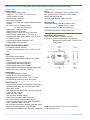
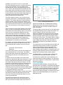
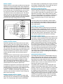
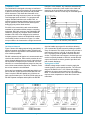
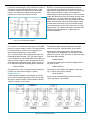
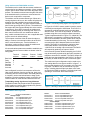
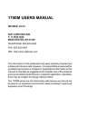
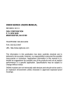
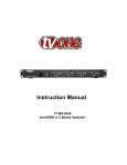
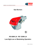
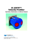
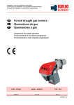
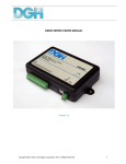
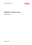
D3000 and D4000 SERIES
COMPUTER TO ANALOG OUTPUT MODULES
D3000 and D4000 FEATURES
• Analog output ranges: 0-1V, ±1V, 0-5V, ±5V, 0-10V,
±10V, 0-20mA, 4-20mA.
• Communicates in ASCII with RS-232 or RS-485 serial
ports.
• Programmable high/low output limits.
• 500Vrms output isolation.
• 12-bit output resolution.
• Scaling in engineering units.
• Baud rates: 300 to 38,400.
• Nonvolatile digital calibration.
• Output protection: 240VAC (current output).
±30V (voltage outputs).
• Direct connection to ‘dumb’ terminals or modems.
• Requires +10 to +30Vdc unregulated supply.
• May be located up to 4,000 feet from host (RS-485).
• Addressable: up to 124 units per serial port.
• ‘Bumpless’ manual control inputs.
D4000 PROGRAMMING FEATURES
Provides intelligent features not found in the D3000.
• Fully programmable output slopes: 0.01V/s (mA/s)
to 10,000V/s (mA/s).
• Programmable data scaling to any desired units.
• True analog readback of output signal.
• Programmable starting value.
• Programmable watchdog timer provides orderly
shutdown in the event of host failure.
APPLICATIONS
• Motion control
• Motor speed control
• Robotic welding control
• Interfaces to modems
• Programmable analog source for product test
D3000/4000 SPECIFICATIONS (typical @+25°C and nominal power supply unless otherwise noted.)
Analog Output
• Single channel analog output.
Voltage: 0-1V, ±1V, 0-5V, ±5V, 0-10V, ±10V.
Current: 0-20mA, 4-20mA.
• Output isolation: 500V rms.
• 12-bit output resolution.
• Accuracy: 0.1% FSR max (Integral & Differential Nonlinearity.
• Zero drift: ±30µV/°C (Voltage Output).
±1.0µA/°C (Current Output).
• Span tempco: ±50ppm/°C max.
• 1000 conversions per second.
• Settling time to 0.1% FS: 300µs typ (1ms max).
• Output change manual mode (-FS to +FS): 5s.
• Programmable output slope (D4000): 0.01V/s (mA/s)
to 10,000V/s (mA/s).
• Current output voltage compliance: ±12V.
• Voltage Output drive: 5mA max.
Power
Requirements: Unregulated +10V to +30Vdc, 0.75W
max. (voltage output), 1.0W max. (current output).
Internal switching regulator.
Protected against power supply reversals.
Environmental
Temperature Range: Operating -25°C to +70°C.
Storage -25°C to +85°C.
Relative Humidity: 0 to 95% noncondensing.
Specifications are subject to change without notice.
Mechanicals and Dimensions
Case: ABS with captive mounting hardware.
Connectors: Screw terminal barrier plug (supplied).
Repace with Phoenix MSTB 1.5/10 ST 5.08
or equivalent.
Analog Output Readback (D4000)
• 8-bit analog to digital converter.
• Accuracy over temperature (-25 to +70°C): 2.0% FS
max.
Digital
• 8-bit CMOS microcomputer.
• Digital scaling and calibration stored in nonvolatile
memory.
• Programmable High/Low output limits.
• Programmable data scaling (D4000).
• Programmable starting value (D4000).
• Programmable watchdog timer provides orderly shutdown in the event of host failure (D4000).
Digital Inputs
• Three digital inputs per module.
• Voltage levels: ±30V without damage.
• Switching levels: High, 3.5V min., Low, 1.0V max.
• Internal pull up resistors for direct switch input.
Communications
• Communications in ASCII via RS-232C, RS-485 ports.
• Selectable baud rates: 300, 600, 1200, 2400, 4800,
9600,19200, 38400.
• NRZ asynchronous data format; 1 start bit, 7 data bits,
1 parity bit and 1 stop bit.
• Parity: odd, even, none.
• User selectable channel address.
• ASCII format command/response protocol.
• Up to 124 multidrop modules/host serial port.
• Communications distance up to 4,000 feet (RS-485).
• Can be used with “dumb” terminal.
• All communications setups (address, baud rate, parity)
stored in nonvolatile memory using EEPROM.
• Checksum can be added to any command or response.
NOTE: Spacing for mounting screws = 2.700" (6.858 cm).
Screw threads are 6 X 32.
GENERAL DESCRIPTION & BLOCK DIAGRAM
The DGH D3000/4000 series are complete computer-toanalog output interfaces. They are designed to be
mounted remotely from a host computer and communicate, in ASCII, with standard RS-232 and RS-485 serial
ports. Simple ASCII commands are used to control a 12bit DAC (Digital-to-Analog Converter) which is scaled to
provide commonly used current and voltage ranges. An
8-bit CMOS microprocessor provides an intelligent
interface between the host and the DAC.
The DGH modules are easy to use. You do not need
engineering experience in complicated data acquisition
hardware. This modular approach to data acquisition is
extremely flexible, easy to use and cost effective. The
modules can be mixed and matched to fit the application.
They can be placed remote from the host and from each
other. You can string up to 124 modules on one set of
wires.
Figure 1 shows a functional block diagram of the D3000/
4000. The DAC converts digital data derived from host
commands into the desired analog output. The microprocessor receives commands and data from the host
computer through an RS-232 or RS-485 port. A wide
variety of two-or-three-letter commands from the host
control the DAC, read status information, and configure
the module to fit your requirements. Responses to
commands are produced by the microprocessor and
transmitted back to the host over the serial link.
For example, the module's analog output is controlled by
the Analog Output (AO) command from the host. The
host command/module response sequence looks like
this:
Command: $1AO+00010.00
Response: *
If a 0-20mA output module is used for this example, the
AO command produces a 10mA output. The module
performs the output function and responds with a '*' as an
acknowledgement that the command has been performed.
In response to host commands, the microprocessor
produces the appropriate digital data necessary to control
the DAC. Digital data is transmitted to the DAC through
opto-isolators that provide electrical isolation. The DAC
produces a precise analog current that is directly proportional to the magnitude of the digital data. The DAC
output current is processed and amplified by signal
conditioning circuits to produce the desired output voltage
or current. Output protection circuits protect the module
from potentially damaging output faults.
An EEPROM (Electrically Erasable Programmable ReadOnly Memory) retains important data such as the address, baud rate, parity and calibration data even if the
module is powered down.
The D4000 series features an 8-bit ADC (Analog to
Digital Converter) that monitors the output signal. The
ADC input is tied to the analog output and converts the
Figure 1. D3000/4000 Block Diagram.
signal level to digital data. The digital data is optically
isolated and may be read by the microprocessor. The
ADC allows the user to monitor the output signal and
ensure its integrity.
The power supply converts the raw 10 to 30V input power
into regulated voltages used to operate the module. The
power it supplies to the DAC and output circuits is
transformer isolated from the input power and communications connections. The transformer and opto-isolators
provide an isolation barrier between the output section
and the rest of the circuitry. The isolation barrier is helpful
in breaking ground loops, isolating troublesome commonmode voltages and protects the host and module in
cases where the output may accidentally contact AC
power lines.
The combination of an accurate high-resolution DAC and
a dedicated microprocessor produces a very powerful
system for generating process control signals. The
microprocessor provides software addressing for multidrop capability, data formatting in engineering units, limit
checking, digital calibration and many other features not
possible with unintelligent analog output systems.
The D3000/4000 are compatible with the DGH D1000
and D2000 series and may be mixed in any order.
All modules are supplied with screw terminal plug connectors and captive mounting hardware. The connectors
allow system expansion, reconfiguration or repair without
disturbing field wiring.
UTILITY SOFTWARE
Complimentary Utility Software is included with each
purchase order. The software is compatible with Windows
95, 98, NT 4.0+, 2000 operating systems and distributed
on CD-ROM. The Utility Software simplifies configuration
of all user-selectable options such as device address,
baud rate and filtering constants. The latest version of our
software is always downloadable from our web site at
www.dghcorp.com.
MANUAL MODE
Manual Up/Down control option provides a local operator
interface to control the analog output value independent
of the host. As shown in Figure 2, the analog output may
be moved up or down by shorting the UP* or DN* inputs
to the GND terminal. Grounding both pins at once holds
the output at its present value and inhibits any output
commands from the communications ports. The control
inputs may also be logic signals from other equipment.
The manual mode controls the output with a linear slope.
The slope rate on D3000 modules is fixed and scaled so
that a full-scale output change takes 5 seconds.
The manual slope is independent of the slopes used with
the computer controlled output. The manual rate may be
changed with the Manual Slope command.
INPUT DATA SCALING (D4000)
All D3000 and D4000 modules are factory set with data
values in millivolts or milliamps. The D4000 allows the
user to scale the input data to any desired units. In many
applications a change in input scaling makes the data
easier to read and interpret. For example, a D4000 used
to control a valve actuator may be easier to use if the
data is scaled with a range of 0-100% rather than 420mA.
The input scaling may be changed by using the Maximum and Minimum commands to assign input data values corresponding to the module's maximum and minimum output values.
STARTING VALUE (D4000)
When a D4000 module is powered up from a cold start,
the analog output is automatically forced to a user-programmable predetermined starting value. This feature is
useful for cold-starting systems in a controlled manner.
Usually the starting value is specified as a “safe” condition to protect equipment and material from damage.
Figure 2. Manual Up/Down Control.
SLOPE CONTROL (D4000)
Most DACs provide a step function when a new output
value is desired. That is, the analog output change is instantaneous subject only to DAC settling time. In many
applications this characteristic is undesirable and a gradual controlled output slew rate is more appropriate. In applications where controlled output rates are needed, precious host computer time must be used to continually
monitor and step the DAC until the desired output is
reached.
The D4000 allows controlled output slopes automatically
without host computer intervention. User-programmable
output slew rates are stored in nonvolatile memory. If a
command is sent to the D4000 to change the output
value, the output will automatically slope to the new
value at the specified rate. The nonvolatile slope value is
restored each time the module is powered up.
The D4000 microprocessor controls the output slew rate
by updating the DAC at a rate of 1000 conversions per
second at precise 1ms intervals. In this manner the DAC
is smoothly stepped until the final output value is
reached. The DAC's incremental output steps and its
conversion rate combine to make the output change appear to be a linear ramp.
MANUAL SLOPE CONTROL (D4000)
The D4000 allows the user to specify the output slope
when the output is controlled by the manual UP/DOWN
inputs. The manual slope data is stored in EEPROM.
WATCHDOG TIMER (D4000)
The D4000 contains a user-programmable software timer
to provide an orderly shutdown of the output signal in the
event of host computer or communications failure. The
timer is preset using the Watchdog Timer command to
specify a timer interval in minutes. The timer is continually incremented in software. Each time the D4000 module receives a valid command, the timer is cleared to
zero and restarted. If the timer count reaches the preset
value, the output will automatically be forced to slew to
the starting value using the present output slope rate.
The starting value should be programmed to provide a
"safe" output value to minimize damage and disruption to
the system under control.
ANALOG READBACK (D4000)
The Read Data command in the D3000/4000 series provides a status report of the output of a module. However,
the data obtained with this command only indicates the
digital data that is being transferred from the onboard microprocessor to the DAC. It does not indicate whether the
the DAC output is correct. It cannot detect fault conditions such as shorts or open circuits.
The D4000 series contains an ADC that provides true
readback of the analog output signal. The ADC is independent of the DAC. The ADC provides true analog readback data to the microprocessor. While not intended to
be a highly accurate measurement of the output signal,
the ADC greatly enhances the user’s confidence that the
analog output is being produced as intended. Output fault
conditions from improper wiring or loads can be easily
detected. The ADC also provides a form of redundancy
to ensure that the module is working properly.
COMMAND SET
The D3000/4000 series uses a simple command/
response protocol for communication. A module must
be interrogated by the host to obtain data. A module
can never initiate a command sequence. A typical
command/response sequence could look like this:
Command: $1RD
Response: *+00075.00
A command is initiated with a command prompt, which
may be a dollar sign ($) or a pound sign (#). Following
the prompt a single address character must be transmitted. Each module on a communications bus must be
setup with a unique address. In this case, the command is directed to module address ‘1’. The address is
followed by a two-or-three-character command which in
this case is RD for Read Data. The command is
terminated with a carriage return.
After module address ‘1’ receives the command it will
respond with the analog output data. The response
begins with a response prompt, which is an asterisk (*).
The data is read back in a standardized format of sign,
5 digits, decimal point, and 2 more digits. All D3000/
4000 modules represent data in the same standard
format.
Table 1 shows all of the D3000/4000 commands. For
each case, a sample command and response is shown.
Note that some commands only respond with an * as
an acknowledgment. For clarity, Table 1 separates
D4000 commands from the commands that are common to both the D3000 and D4000. Table 1 also
separates write protected commands from commands
that are not write protected.
For greater data security, options are available to echo
transmitted commands and to send and receive checksums. The # command prompt requests a response
message from the module that begins with an *,
followed by the channel address, command, data (if
necessary) and checksum. This response echoes the
channel address and command for verification and
adds checksum for error checking. Checksum is a two
character hexadecimal value that can be added to the
end of any command message, regardless of prompt,
at your option. Checksum verifies that the message
received is exactly the same as the message sent.
The D3000/4000 performs extensive error checking on
commands and responds with an error message if
necessary. All error messages start with an error
prompt (?) followed by the channel address and the
error description. In the following example, the D3000/
4000 does not recognize ‘AB’ as a valid command.
Command: $1AB
Response: ?1 COMMAND ERROR
Table 1 D3000/4000 Command Set
Command Definition
D3000/4000 Commands
ACK Acknowledge
AO
Analog Output
DI
Digital Input
HX
Hex Output
RAO Read Analog Output
RD
Read Data
RHI Read High Limit
RID Read Identification
RLO Read Low Limit
RMS Read Manual Slope
RMX Read Maximum
RMN Read Minimum
RS
Read Setup
RSU Read Setup
WE Write Enable
Typical
Command
Message
Typical
Response
Message
$1ACK
$1AO+00020.00
$1DI
$1HX0FFF
$1RAO
$1RD
$1RHI
$1RID
$1RLO
$1RMS
$1RMX
$1RMN
$1RS
$1RSU
$1WE
*
*
*0007
*
*+00017.50
*+00012.34
*+00020.00
*BOILER
*+00000.00
*+00004.00
*+00020.00
*+00000.00
*31070140
*31070140
*
The following D3000/4000 commands are Write Protected
HI
High Limit
$1HI+00015.00
*
ID
Identification
$1IDBOILER
*
LO
Low Limit
$1LO+00004.00
*
RR
Remote Reset
$1RR
*
SU
Setup
$1SU310701C0
*
TMX Trim Maximum
$1TMX+00020.17 *
TMN Trim Minimum
$1TMN+00000.95 *
D4000 Commands
RAD Read Analog Data
RPS Read Present Slope
RSL Read Slope
RSV Read Starting Value
RWT Read Watchdog Timer
$1RAD
$1RPS
$1RSL
$1RSV
$1RWT
*+00012.34
*+00001.00
*+00001.00
*+00005.00
*+00010.00
The following D4000 commands are Write Protected
MS
Manual Slope
$1MS+00001.00
*
MX
Maximum
$1MX+00100.00
*
MN Minimum
$1MN-00025.00
*
SL
Slope
$1SL+00001.00
*
SV
Starting Value
$1SV+00004.00
*
TRX Trim Readback Maximum $1TRX
*
TRN Trim Readback Minimum $1TRN
*
WT Watchdog Timer
$1WT+00010.00
*
WSL Write Slope To EEPROM $1WSL+00100.00 *
COMMUNICATIONS
The D3000/4000 is designed to be easy to interface to
all popular computers and terminals. All communications
to and from the module are performed with printable
ASCII characters. This allows the information to be
processed with string functions common to most highlevel languages such as BASIC. For computers that
support standard interfaces such as RS-232C, no
special machine language software drivers are necessary for operation. The ASCII format makes system
debugging easy with a dumb terminal.
RS-232C is the most widely used communications
standard for information transfer between computing
equipment. RS-232C versions of the D3000/4000 will
interface to virtually any computer without additional
hardware. RS-232C is not designed to be used as a
multiparty system; however the D3000/4000 modules
can be daisy-chained, as shown in Figure 3, to allow
many modules to be connected to a single communica-
tions port. In this network, any characters transmitted by
the host are received by each module in the chain and
passed on to the next station until the information is
echoed back to the host. In this way all commands given
Figure 3. RS-232 Daisy Chain Network.
APPLICATIONS
100 Channel Network
Figure 5 shows 100 analog outputs being controlled by a
personal computer and D4000 modules. RS-485 is the
obvious choice for high channel count networks because
of its multidrop capability.
RS-485 is inherently half-duplex so it cannot transmit and
receive at the same time. Each module contains its own
unique channel address that you specify. Only the channel requested will respond to your command. The modules work on a command/response protocol so they can
never initiate a transmission sequence. Therefore, errors
due to bus contention are eliminated.
Since very few computers or terminals have built-in support for RS-485, a DGH A1000 RS-232C/RS-485 Converter is required. RS-485 handles only 32 drivers on
each communications port. The DGH A1000 acting as an
RS-485 Repeater reshapes and amplifies the RS-485
signal to handle as many as 32 more drivers allowing
you to extend the RS-485 network by adding a repeater
every 30 channels. The A1000 converter also provides a
power supply output of +24V @ 1A to power the modules. The supply protects against overloads and short
circuits. To protect the host computer, the host input connection is optically isolated to 1500Vac, and the RS-485
output connections are tied to ground to provide a safe
path for static discharge.
Scaling data in RPM
A D4000 voltage output module is used to supply the
control signal to a motor speed controller. The full scale
range of the D4000 is 0 to +10V. When this voltage is
applied to the motor, speed varies from 100 to 3000
RPM. To command the motor to turn at a specified RPM
requires some computation to obtain the correct command data.
Figure 5a. 100 Channel Network.
by the host are examined by every module in the chain. If
a module is correctly addressed and receives a valid
command, it transmits a response on the daisy chain
network. The response is rippled through any other
modules in the chain until it reaches the host.
RS-485 is a communications standard developed for
multi-dropped systems that can communicate at high
data rates over long distances, as shown in Figure 4. RS485 is similar to RS-422 in that it uses a balanced
differential pair of wires switching from 0 to 5V to communicate data. RS-485 receivers can handle common mode
voltages from -7 to +12V without loss of data, making
them ideal for transmission over great distances. RS-485
differs from RS-422 by using one balanced pair of wires
for both transmit and receive. Since an RS-485 system
cannot transmit and receive at the same time it is a halfduplex system. For systems that require more than a few
modules, long wiring distances, or high speed, we
recommend RS-485.
Figure 4. RS-485 Multidrop Network.
For instance, to command the motor to go at 1500 RPM
requires an output voltage of 4.666V. This data is difficult
to read and interpret. A solution to this problem is to
scale the input data directly in units of RPM.
The - full scale output of 0V is assigned the value 100
RPM with the MN command. The + full scale output of
+10V is assigned the value 3000 RPM with the MX command. Once the endpoint values are assigned, all other
data values are interpolated linearly. Now to set the motor to 1500 RPM requires the analog output command:
The Minimum (MN) command assigns an input data
value of 0mA to the - full scale output of the module.
Using the two scaling points (4mA = 0%) and (20mA =
100%) and a bit of computation, we find that 0mA interpolates to a value of -25%. This value is used in the argument of the MN command:
$1MN-00025.00
The maximum scaling point of 20mA is assigned the input value of 100%:
$1MX+00100.00
$1AO+01500.00
The data is much easier to interpret since the scaling is
in RPM. The actual output voltage is +4.666V.
Scaling data in %
A valve actuator accepts a 4-20mA signal: at 4mA the
valve is fully closed and at 20mA the valve is fully open.
We wish to rescale a D4252 0-20mA module to accept
data of 0% closed to 100% open.
The module is now scaled in percentage of valve opening. To set the valve to 50% opening:
$1AO+00050.00
In this case the D4000 module produces an output of
12mA, opening the valve halfway.
Figure 5b. 100 Channel Network.
Using modems and D3000/4000 modules
The modules can be used with auto-answer modems at
remote sites for long-distance operation. A host computer
may be used to call a modem and check the status of the
process. The modules communicate using RS-232 which
is the standard used by modems to communicate with
devices such as printers or computers.
The modem must be an auto-answer type. When an incoming telephone call occurs, the modem will pickup the
telephone line and establish communication with the
computer at the other end. The other modem function required is the Ignore RS-232C DTR line. The modules do
not support the Data Transmit Ready line so the modem
must ignore it. Since DTR is ignored, the modem and
module are always ready for incoming calls. Other modem control functions such as: enable auto redial on
busy, enable command mode, etc. are not applicable and
may be set to their default settings.
The computer must have either an internal modem or
ability to connect to an external modem via an RS-232
serial communications port. Terminal software, or
equivalent, is also required to control the modem and
communicate with the remote module.
All communications parameters needed to establish communication with the remote module are shown in the following table.
Baud rate
Parity
Data bits
Stop bits
Auto-dial
Auto-ans.
Terminal
software
Computer
modem
Remote
modem
D4000
module
1200
N
7
1
1200
1200
1200
N
On
On
Once configured, have the host computer call the site.
Upon carrier detection from the remote site, begin communicating with the remote module. After data gathering
is complete, use the terminal software to hang up the
telephone. Once the telephone is back on the hook, the
remote modem will reset itself and await the next call.
Transmitting analog signals over long distances
The D4000 models may be paired with an appropriate
D1000 module to transmit analog signals over great distances without a host computer.
Figure 6. Transmitting analog signals over long distances.
In Figure 6, a D1251C sensor module is used to convert
a 0-20mA process signal to ASCII data. The D1251C is
operated in continuous output mode to produce data
without a host. The D1251C will produce an ASCII output data string after every analog-to-digital conversion.
Typical output data shown in Figure 6 is *+00020.00. The
data output is connected to a modem which allows the
data to be transmitted to another modem which may be
located thousands of miles away. The receive modem
reconstructs the ASCII data and feeds it to the D4251
module. The D4251 is configured in continuous input
mode which allows it to accept the data string of
*+00020.00 as an analog output command. The D4251
will respond by producing an output of 20mA.
In this case the process variable sensed by the D1251C
may be accurately reproduced by the D4251 anywhere a
telephone connection is available. The D4251 output will
follow the input signal applied to the D1251C. No host is
necessary on either end to provide a continuous signal.
The continuous input configuration may be used to convert analog data from one type to another. In figure 7, a
thermocouple signal may be converted to a 0-20mA analog output. The D4251 may be rescaled to any input
range, including thermocouple input data. In this case,
we rescale the D4251 to produce a 0-20mA signal corresponding to 100°-300°F at the thermocouple.
Figure 7. Rescaling a temperature input to a 0-20mA output.
D3000/D4000 Ordering Guide
MODEL
OUTPUT RANGE/INPUT
Voltage Output
D3121/D4121
±1V Output/RS-232C Input
D3122/D4122
±1V Output/RS-485 Input
D3131/D4131
±5V Output/RS-232C Input
D3132/D4132
±5V Output/RS-485 Input
D3141/D4141
±10V Output/RS-232C Input
D3142/D4142
±10V Output/RS-485 Input
D3161/D4161
0 to 1V Output/RS-232C Input
D3162/D4162
0 to 1V Output/RS-485 Input
MODEL
OUTPUT RANGE/INPUT
D3171/D4171
0 to 5V Output/RS-232C Input
D3172/D4172
0 to 5V Output/RS-485 Input
D3181/D4181
0 to 10V Output/RS-232C Input
D3182/D4182
0 to 10V Output/RS-485 Input
Current Output
D3251/D4251
0 to 20mA Output/RS-232C Input
D3252/D4252
0 to 20mA Output/RS-485 Input
D3261/D4261
4 to 20mA Output/RS-232C Input
D3262/D4262
4 to 20mA Output/RS-485 Input