1
8 /R8
®
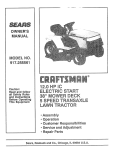
MODEL NUMBER 917.258660
OWNER'S MANUAL
e Assembly
Operation
o Customer Responsibilities
e Service and Adjustments
o Repair Parts
CAUTION:
Read
and follow
FOR CONSUMER
I
all safety
ASSISTANCE
rules and instructions
before
operating
HOT LINE, CALL THIS TOLL FREE NUMBER:
this equipment.
1-800-659-5917
i_
SAFETY
Practices RULES
for Ride-On
Safe Operation
Mowers
IMPORTANT:
THIS CUTTING MACHINE tS CAPABLE OF AMPUTATING
HANDS AND FEETAND
THROWING OBJECTS
FAILURE TO OBSERVE THE FOLLOWING SAFETY INSTRUCTIONS
COULD RESULT IN SERIOUS INJURY OR DEATH
Io
•
•
•
•
•
•
•
•
o
•
•
•
.
o
o
Ii.
GENERAL
OPERATION
Read, understand, and follow all instructions in the manual
and on the maci_ine before starting
Only allow responsible adults, who are familiar with the
instructions, to operate the machine.
Clear the area of objects such as rocks, toys, wire, etc,
which could be picked up and thrown by the blade.
Be sure the area is clear of other people before mowing. Stop
machine if anyone enters the area.
Never carry passengers.
Do not mow in reverse unless absolutely necessary. Always
took down and behind before and while backing.
Be aware of the mower discharge direction and do not point
it at anyone Do not operate the mower without either the
entire grass catcher or the guard in place.
Stow down before turning.
Never leave a running machine unattended Always turn off
blades, set parking brake, stop engine, and remove keys
before dismounting.
Turn off blades when not mowing
Stop engine before removing grass catcher or unclogging
chute
II!.
Tragic accidents can occur if the operator is not alert to the
presence
of children°
Children are often attracted to the
machine and the mowing activity.
Never assume that
children will remain where you last saw them
•
Keep children out of the mowing area and under the watchful
care of another responsible adult
•
Be alert and turn machine off if children enter the area
•
•
•
•
Before and when backing, look behind and down for smaff
children
Never carry children,, They may fall off and be seriously
injured or interfere with safe machine operation
Never allow children to operate the machine,
Use extra care when approaching blind corners, shrubs,
trees, or other objects that may obscure vision.
IV. SERVICE
•
Mow only in daylight or good artificial light
Do not operate the machine while under the influence of
aIcohol or drugs.
Watch for traffic when operating near or crossing roadways.
Use extra care when loading or unloading the machine into
a trailer or truck_
SLOPE
CHILDREN
.
•
OPERATION
•
Slopes are a major factor related to Ioss-of_control
and
tipover accidents,
which can result in severe injury or
death. All slopes require extra caution. If you cannot back
up the slope or if you feel uneasy on it, do not mow it.
•
.
DO:
•
Mow up and down slopes, not across
.
Remove obstacles such as rocks, tree limbs, etc
•
Watch for holes, ruts, or bumps.
Uneven terrain could
overturn the machine
Tall grass can hide obstacles.
•
Use slow speed Choose a low gear so that you will not have
to stop or shift while on the slope
•
Follow the manufacturer's
recommendations for wheel
weights or counterweights to improve stability
•
Use extra care with grass catchers or other attachments
These can change the stability of the machine.
•
Keep all movement on the slopes slow and gradual Do not
make sudden changes in speed or direction.
•
Avoid starting or stopping on a slope tf tires lose traction,
disengage the blades and proceed slowly straight down the
slope,
•
•
•
•
Use extra care in handling gasoline and other fuels They are
flammable and vapors are explosive_
Use only an approved container
Never remove gas cap or add fue! with the engine
running Allow engine to cool before refueling Do not
smoke
Never refuel the machine indoors
Never store the machine or fuel container inside where
there is an open flame, such as a water heater.
Never run a machine inside a closed area
Keep nuts and botts, especially blade atlachment bolts, tight
and keep equipment in good condition
Never tamper with safety devices
Check their proper
operation regularly
Keep machine free of grass, leaves, or other debris build-uF
Clean oil or fuel spillage.
Allow machine to cool before
storing
Stop and inspect the equipment if you strike an object
Repair, if necessary, before restarting
Never make adjustments or repairs with the engine running.
Grass catcher components are subject to wear, damage, and
deterioration, which could expose moving parts or allow
objects to be thrown. Frequently check components and
replace with manufacturer's recommended pads, when necessary.
Mower blades are sharp and can cut Wrap the blade(s) or
wear gloves, and use extra caution when servicing them
Check brake operation frequently. Adjust and service as
required.
safety
precautions,
it
means
Lookfor
this symbol
to point
out important
CAUTION!_J
BECOME
ALERT!!!
YOUR
SAFETY IS INVOLVED.
DO NOT:
•
°
°
°
•
Donotturnonslopesunlessnecessary,
andthen, turnslowty
and gradually downhill, if possible.
Do not mow near drop-offs, ditches, or embankments. The
mower could suddenly turn over if a wheel is over the edge
of a cliff or ditch, or if an edge caves in
Do not mow on wet grass. Reduced traction could cause
sliding.
Donot tryto stabilize the machine by putting your foot on the
ground
Do not use grass catcher on steep slopes.
I
wire and place wire where it cannot contact
spark plug in order to prevent accidental
starting
setting
up, transporting,
CAUTION: when
Always
disconnect
spark plug
adjusting or making repairs.
WARNING A
The engine exhaust from this product contains
chemicals known to the State of California
to
cause cancer, birth defects, or other reproductive harm.
2
I
I
PRODUCT
CONGRATULATIONS
on your purchase of a Sears
Tractor.. It has been designed, engineered and manufactured to give you the best possibte dependability and
performance°
Should you experience any problem you cannot easily
remedy, please contact your nearest Sears Authorized
Service Center/Department
Department_ We have competent, weiHrained technicians and the proper tools to
service or repair this tractor.
Please read and retain this manual. The instructions will
enable you to assemble and maintain your tractor properly.
Always observe the "SAFETY RULES".
MODEL
NUMBER
SERIAL
NUMBER
SPECIFICATIONS
HORSEPOWER:
19 5
GASOLINE CAPACITY
AND TYPE:
3.5 GALLONS
UNLEADED REGULAR
OIL TYPE (APf-SF/SG):
SAE 30 (above 32°F)
SAE 5W_30 (beiow 32°F)
OIL CAPACITY:
3.0 PINTS
i SPARK PLUG:
i (GAP: .030")
CHAMPION
RJ19LM
VALVE CLEARANCE:
INTAKE:
EXHAUST:
.004" - ..006"
.007" - °009"
GROUND SPEED (MPH):
FORWARD:
1st
2nd
3rd
4th
5th
6th
REVERSE:
917,258660
DATEOF PURCHASE
THE MODEL AND S ERIAL NUMBERS WILL BE FOUND
ON A PLATE UNDER THE SEAT.
YOU SHOULD RECORD BOTH SERIAL NUMBER AND
DATE OF PURCHASE AND KEEP IN A SAFE PLACE
FOR FUTURE REFERENCE.
MAINTENANCE
AGREEMENT
A Sears Maintenance
Agreement
uct. Contact your nearest Sears
CUSTOMER
.
.
o
is available on this F' dstore for details.
TIRE PRESSURE:
FRONT:
REAR:
CHARGING SYSTEM:
3 AMPS BATTERY
5 AMPS HEADLIGHTS
BATTERY:
AMP/HR:
MIN CCA:
CASE SIZE:
BLADE BOLT TORQUE:
30-35 FT LBS
RESPONSIBILITIES
Read and observe the safety rules.
Follow a regular schedule in maintaining, caring for and
using your tractor.
Follow the instructions
under"Customer
Responsibilities" and "Storage" sections of this owner's manual.
14 PSI
10 PSI
30
240
U1R
(if any),. If a spark arrester is used, it should be maintained
in effective working order by the operator
In the state of California the above is required by law
(Section 4442 of the California Public Resources Code).
Other states may have similar laws. Federal laws apply on
federal lands. A spark arrester for the muffler is available
through your nearest Sears Authorized Service Center/
Department (See REPAIR PARTS section of this manual).
WARNING:
This tractor is equipped with an internal
combustion engine and should not be used on or near any
unimproved forest..covered, brush-covered or grass-covered land unless the engine's exhaust system is equipped
with a spark arrester meeting applicable local or state laws
LIMITED TWO YEAR WARRANTY
11
t 5
23
35
44
57
17
ON CRAFTSIVtAN
RIDING EQUIPMENT
For two (2) years from the date of purchase, if this Craftsman Riding Equipment is maintained, lubricated and tuned up according
to the instructions in the owner's manual, Sears will repair or replace, free of charge, any parts found to be defective in material or
workmanship..
This Warranty does not cover:
Expendable items which become worn during normal use, such as blades, spark plugs, air cleaners, belts, etc
°
Tire replacement or repair caused by punctures from outside objects, such as nails, thorns, stumps, or glass,
°
Repairs necessary because of operator abuse, negligence, improper storage or accident or the failure to maintain the
equipment according to the instructions contained in the owner's manual
°
Riding equipment used for commercial or rental purposes.
LIMITED 90 DAY WARRANTY
ON BATTERY
For ninety (90) days from date of purchase, if any battery included with this riding equipment proves defective in material or
workmanship and our testing determines the battery will not hold a charge, Sears will replace the battery at no charge..
IN-HOME WARRANTY SERVICE ON YOUR CRAFTSMAN RIDING EQUIPMENT IS AVAILABLE AT NO-CHARGE FOR 30
DAYS FROM THE DATE OF PURCHASE. PLEASE CONTACT YOUR NEAREST SERVICE CENTER. AFTER 30 DAYS FROM
THE DATE OF PURCHASE, WARRANTY SERVICE IS AVAILABLE BY TAKING YOUR CRAFTSMAN RIDING EQUIPMENT TO
YOUR NEAREST SEARS SERVICE CENTER, (1N-HOME WARRANTY SERVICE WILL STILL BE AVAILABLE AFTER 30 DAYS
FROM THE DATE OF PURCHASE BUT A STANDARD TRIP CHARGE WILL APPLY.)
THIS WARRANTY APPLIES ONLY
WHILE THIS PRODUCT IS IN THE UNITED STATES..
This Warranty gives you specific legal rights, and you may also have other rights which may vary from state to state.
SEARS,
ROEBUCK
AND CO.
D/817 WA, HOFFMAN
3
ESTATES,
IL 60179
TABLE OF CONTENTS
SAFETY RULES ............................................................
2
PRODUCT SPECIFICATIONS ...................................... 3
CUSTOMER RESPONSIBILITIES ..................... 3, 17-19
WARRANTY .............................................................
;..,. 3
TRACTOR ACCESSORIES .......................................... 5
ASSEMBLY ..............................................................
7-10
OPERATION ...........................................................
11-15
MAINTENANCE SCHEDULE ......................................
16
SERVICE AND ADJUSTMENTS ............................ 20-26
STORAGE ...................................................................
27
TROUBLESHOOTING ............................................
28-29
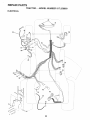
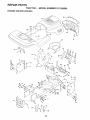
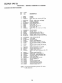
REPAIR PARTS - TRACTOR ................................. 32-49
REPAIR PARTS - ENGINE .................................... 50-55
PARTS ORDERING/SERVICE .................. BACK PAGE
iNDEX
A
Accessories ............................................ 5
Adjustments:
Brake ............................................
22
Carburetor
................................... 25
Mower:
Front-To-Back .......................... 2!
Side-To-Side ......................... 21
Throttle Control Cable ............... 25
Ai_;Filler, Engine ...........................................
18
Air' Screen, Engine .........................
18
Assembly
7-109
B
.......................................
Battery:
Charging ........................................ 17
Cleaning ..............................................17
Starting with Weak Battery .......... 24
Storage
27
Terminals ....................................... 17
Belts:
Motion Drive
Removal/Replacement
........... 22
Mower Blade Drive
RemovaltReplacement
.............22
Blade:
............................................
Sharpening .................................
17
Replacement ...............................
17
Brake Adjustment ....................................22
C
Carburetor Adjustment ............................25
Controls, Tractor ..........................................
13
Customer Responsibilities ...........3,17-19
Engine:
Air Filter ...........................................
18
Air Screen, Engine ................... 18
Battery ...........................................17
Cooling Fins, Engine ..................19
Engine Oil ................................ 18
Fuel Filter .................................... 19
Spark Plugs ............................. 19
Tractor:
Blades ......................................... 17
Lubrication Chart ....................... 16
Maintenance Schedule ...............16
Tire Care ..................................
8,17,23
Cutting Height, Mower ...........................13
E
Electrical:
Interlocks and Relays .................. 24
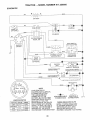
Schematic ....................................... 31
Wiring Diagram ...............................32
Engine:
Air Filter ..............................................18
Air Screen ..................................
18
Cooling Fins, Engine ......................19
Oil Change .........................
18
Oil Level .................................. 13,18
Oil Type ........................
18
Preparation ...............................
14
Repair Parts
50-55
Starting ..................................
14
Storage
27
F
Filters:
Air ...................................................... 18
Fuel .....................................................19
Fuel:
....................
..........................................
Type ..................................
Storage .............................
Fuse .................................................
G
!4
27
24
Gauge Wheels ...................................
10
H
Hood Removal/Installation
.................. 24
L
Leveling Mower Deck .............................21
Lubrication Chart ................................... 16
M
Maintenance Schedule ..........................16
Mower:
Adjustment, Front4o-Back ........ 21
Adjustment, Side-to-Side .............. 21
Blade Sharpening .......................... 17
Blade Replacement .........................17
Cutting Height .....................................
13
Installation ...................................... 20
Operation
...................................
1
1
--1
.......................................................
..................................
4
Spark Attester
11 - t 5
t3q4
5
........................... 3,40
P
Perking Brake ...................................
13
Parts Bag
6
Parts, Replacement/Repair
........... 32-49
Product Specifications .................................
3
...................................................
R
Repair Parts ....................
S
,..........
32-49
Safety Rules .........................
2
Seat ..........................................
8
Service and Adjustments .................20-26
Brake ...............................
22
Carburetor ...................................
25
Fuse ......................................
24
Hood Removal/Installation
.....
24
Motion Drive Belt
Removal/Replacement
..... 22
Mower Blade Drive Belt
Removal/Replacement
.......... 22
Mower Adjustment:
Front4o-Back .................
21
Side4o-Side ..................
21
Mower lnstaJtation ............
20
Mower Removal .......................... 20
Tire Care ..........................
8,17,23
Slope Guide Sheet ................................ 56
Spark Plugs ...............................................19
Specifications
3
Starting the Engine ............................14-15
Steering Wheel ................................. 7,23
Stopping the Tractor .............................. 13
Storage .................................................... 27
.........................................
T
Throttle Control Cable Adjustment ..... 25
Tires ...........................................
8,17,23
5
Removal ....................................... 20
Mowing Tips
15
Muffler
19
Spark Arrester
3,40
Mulcher Plate ........................................... 9
O
Oil:
Cold Weather Conditions ..... 14,18
Engine ......................................................
18
Storage ............................................ 27
............................................................
Operation ....................................
Operating Mower
..............
Options:
Accessories .........................
Trouble Shooting Chart
.............
28°29
Transaxle Repair Parts .................. 48-49
W
Warranty .................................................... 3
Wiring Diagram ................................... 32
Wiring Schematic ..........................
31
iii
,i,,
i
i
,i
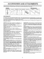
,CCESSORIES
.....
AN
......................
ATTACHMENTS
These accessories and attachments were available through most Sears retail outlets and service centers when the tractor was purchased
Most Sears stores can order these items for you when you provide the model number of your tractor
ENGINE
SPARK PLUG
MAINTENANCE
GAS CAN
ENGINE OIL
FUEL STABILIZER
AIR FILTER
BLADES
BELTS
PERFORMANCE
Sears offers a wide variety of attachments that fit your tractor
you This list was current at the time of publication; however,
may be made in these attachments, or some may no longer
accessories
and attachments
that are available for your
Most of these attachments
attaching and detaching
Many of these ere listed below with brief explanations of how they can help
it may change in future years - more attachments may be added changes
be availabte or fit your model Contact your nearest Sears store for the
tractor,
do not require additional hitches or conversion
AERATOR promotes deep root growth for a healthy lawn. Tapered 2,5_inch steel spikes mounted on 10-inch diameter discs
puncture holes in soil at close intervals to let moisture so_ in.
Steel weight tray for increased penetration
BAGGER lets you collect
grass ctlppings and ieaves for a
healthier, nearer looking Iawn Two Permanex containers hold
30-gallon plastic bags.
kits (those that do are indicated) and are designed for easy
SNOWBLADEforsnowremovalonly.
14-inchhigh 48-inchwide
blade clears 42-inch path when angled teft or righto Raises, lowers
w{thside]ever,
Adjustableskids;
replaceable, reversiblescraper
bar (Use with tire chains and wheel weights and/or rear drawbar
weight,)
SNOWTHROWER has 40-inch swath Drum-type auger handles
powdery and wet/heavy snow, Mounts easily with simple pin
arrangement
Discharge chute adjusts from tractor seat, 6-inch
diameter spout discharges snow 10 to 50 feet, Lift controlled at
tractor seat. (Use with chains and wheel weights and/or rear
d rawbar weight,)
SPRAYERS use 12-volt DC electric motor that connects to the
tractor battery or other 12-volt source
Includes booms for
automatic spraying and hand held wand for spot spraying, Wand
has adjustable spray pattern_ For applying herbicides, insecticides, fungicides and liquid fertilizers,.
SPREADER/SEEDERS
make seeding, fertilizing, and weed killing easy. Broadcast spreaders are also useful for granular deicers and sand.
BUMPER protects front end of tractor from damage,
CARTS make hauling easy. Variety of sizes available, p}us
accessories such as side panel kits, too} caddy, cart cover,
protective mat and dolly,
CORING AERATOR takes small plugs out of soil to af[ow moisture and nutrients to reach grass roots
36-inch swath
24
hardened steel coring tips, t 50 tb, capacity weight tray,
EASY OIL DRAIN VALVE makes oil changes easier, faster,
FRONT NOSE ROLLER canters in front of mower deck to reduce
chances of "scalping" on uneven terrain,
CAN G HITCH lets you tow 2 or3 pull-behind attachments at once,
such as sweepers, dethatchers, aerators (not for use with rollers,
carts or other heavy attachments)
GAUGE WHEELS on both sides of the mower deck reduce
chances of "scalping" on uneven terrain For mower decks not so
equipped
MULCH RAKE/DETHATCHER
loosens soil and flips thatch and
matted leaves to lawn surface for easy pickup. Twenty spring tine
teeth Useful to prepare bare areas for seeding. Available for front
or rear mounting,
HIGH PERFORMANCE
REEL-ACTION
SPRING TINE DETHATCHER covers 36-inch wide path and
tosses thatch into _arge hopper, Mounts behind t[actor
MULCHING CLOSE-OUT PLATE KIT. once instafled, fets you
mulch, discharge or bag clippings (bagger optional) without
changing blades For models not equipped as 3-in-1 Convertible
mowers
See "MOWER" in the Repair Parts section of this
manual,
SWEEPERS fet you collect grass clippings and leaves
TILLER has 5 hp engine and 36-inch swath to prepare seed beds.
cultivate and compost garden residue, Tiller has its own bu_lt-in
lift and depth control system and does NOT require a sleeve hitch
Fits any lawn, yard or garden tractor Simply hook up to the tractor
drawbar and go!
Optional
accessories
convert unit for
dethatching, aerating, hi{ling ,without tools,
TIRE CHAINS are heavy duty; closely spaced extra-large cross
Iinks give smooth ride, outstanding tr._ction,
TRACTOR CAB has heavy duty vinyl fabric over tubular steel
frame, ABS plastic top; clear plastic windshield offers 360 degree
visibility Hinged metal doors with catch. Keeps operatorwarm
and dry. Remove vinyl sides and windshields for use as sun
protector in summer, Optional accessories
include:
tinted/
tempered solid safety glass windshield with hand operated wiper;
12-volt amber caution light for mounting on cab top,
VACS for powerful collection of heavy grass clippings and leaves
Optional wand attachment to pick up debris in hard-to-reach
places, VAClCHIPPER includes a chipper-shredder,
WEIGHT BRACKET for drawbar for snow removal applications_
Uses (1) 55 lb weight.
RAMP TOPS AND FEET let you load and unload tractor from a
pickup truck
Use with 2 x 8 or 2 x 10 lumber
ROLLER for smoother lawn surface.
36-inch wide, 18-inch
diameter water-tight drum holds upto 390 Ibs of weight° Rounded
edges prevent harm to turf, Adjustable scraper automatically
cleans drum.
WHEEL WEIGHTS for rear wheels provide needed traction for
snow removal or dozing heavy materials
5
......
-
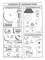
CONTENTS
i1_1
. nuu
I
inn
lU
,i
.....
,
i i,.llnl,,,
lunI,I,,H,U,,
PACK
u n n.i,
.
iiii
ii.,Ulll
OF HARDWARE
.11
Parts Bag contents
lU i,
I" I
' I 'lnl
shown full size
L
Parts packed separately
in carton
...........................
(1) Hex Bolt
3/8-16 x 1
C_
Seat
Video
Cassette
®
(1) Large Flat Washer
(1) Lockwasher
Hex Bolt 5116-18 x 1-1/4
3/8
Steering
Wheel
Mulcher
Plate
(1) Locknut 5116-18
Steering
Boot
(1) Shou{der
Bolt 5/16-18
Parts Bag
(1) Hex Bolt
1/2-13 x 1
was
he,
u .i. ,11
1.1.111
i.u.i
Parts bag contents
........
u...u n"","ll" "U'l''
il
, imnll .........................
_
(2) Shoulder
Bolts
Gauge
/_,_
_,
k.J
_.
"_,=i
_
-
(2)
Lock
Washers
(2)
Screws
#10
x 518
#_o _
} (2) Washers
J 3/16 x 3/4
x 16 Gauge
(2) Hex Bolts 1/4-20 x 3/4
G
_j_
(2) Weld
Nuts #10
®
(2) Hex Nuts 1/4-20
2) Washers 9/32 x 5/8 x 16 Gauge
........................
(2) Lock Washers 1;4 .
Steering Wheel
Adapter
x(2)Washers
7/8 x 14 Gauge
3/8
(2) Gauge
Wheels
©
(1) Lock Washer' 1/2
,_
..f_--....
I
not shown full size
(2) Centerlock Nuts
_o
(2) Keys
k
C_
) Wheel
Steering
Insert
Assemblys
1
Slope Sheet
i
Steering
Extension
Shaft
.,i-,
,11,,
,.................
ii1,1,1,11,11,1,1
H"I'I
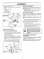
ASSEMBLY
Your new tractor has been assembled at the factory with exception of those parts left unassembled for shipping purposes
To ensure safe and proper operation of your tractor all parts and hardware you assemble must be tightened securely. Use
the correct tools as necessary to insure proper tightness.
TOOLS
REQUIRED
FOR ASSEMBLY
A socket wrench set will make assembly easier. Standard
wrench sizes are listed.
,
(1) 5/16" wrench
(1) 3/4" Socket w/drive rachet
(2) 7/16" wrenches
Phillips Screwdriver
(1) 1/2" wrench
Tire pressure gauge
(2) 9/16" wrench
Utility knife
When right or left hand is mentioned in this manual, it
means when you are in the operating position (seated
behind the steering wheel)
TO REMOVE TRACTOR
UNPACK
•
o
o
'_.....
;_
3/8 HEX BOLT
INSERT
(
LOCK WASHER
.....::: : _i"!.........
/:- : ....
STEERING
WHEEL
_
LARGE FLAT
WASHER
.............]
/
BOOT
FROM CARTON
STEERING
CARTON
ADAPTER
EXTENSION
Remove all accessible loose parts and parts cartons
from carton (See page 6).
Cut, from top to bottom, along lines on alt four corners
of carton, and lay panels flat.
Check for any additional {oose parts or cartons _nd
SHAFT
5/16 HEX BOLT
remove
BEFORE ROLUNG TRACTOR OFF SKID
ATTACH
STEERING
WHEEL
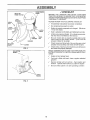
(See Fig. 1)
ASSEMBLE EXTENSION SHAFT AND BOOT
SIide extension shaft onto lower steering shaft. Align
mounting holes ]n extension and lower shafts and
install 5/16 hex bolt and loci<nut Tighten securely.
IMPORTANT: TIGHTEN BOLT AND NUT SECURELY TO
18-22 FT LBSTORQUE
FIG. 1
•
=
•
°
Place gearshift lever in neutral (N) position.
Roll tractor backwards off skid.
•
Remove banding holding discharge guard up against
tractor.
Place tabs of steering boot over tab slots in dash and
push down to secure.
HOW TO SET UP YOUR TRACTOR
INSTALL STEERING WHEEL
o
Position front wheels of the tractor so they are pointing
straight forward..
°
Slide steering wheel adapter onto steering shaft extension
•
Position steering wheel and sleeve assembly so cross
bars are horizontal (left to right) and slide onto adapter
-
Assemble large flat washer, 3/8 lock washer, 3/8 hex
bolt and tighten securely°
-
Snap steering wheel insert into center of steering
wheel
CONNECT
BATTERY
(See Fig. 2)
CAUTION; Do not short battery terminals.
Before connecting
battery, remove metal bracelets,
wristwatch
bands, rings, etc,
Positive terminal must be connected
first to prevent sparking from accidental grounding.
,__
Lift hood to raised position
o Remove protective plastic from tractor hood and grill.
IMPORTANT: CHECK FOR AND REMOVE ANY STAPLES
IN SKID THAT MAY PUNCTURE TIRES WHERETRACTOR
IS TO ROLL OFF SKID.
°
Open terminal access doors, remove terminal protective caps and discard_
•
If this battery is put into service after month and year
indicated on label (label located between terminals)
charge battery for minimum of one hour at 6-t0 amps
TO ROLL TRACTOR
section for location
.
First connect RED battery cable to positive (+) battery
terminal with hex bolt, flat washer, lock washer and hex
nut as shown. Tighten securely.
o
Connect BLACK grounding c_ble to negative (-) battery
terminal with remaining hex bolt, flat washer, lock
washer and hex nuL Tighten securely.
Close terminal access doors
OFF SKID (See Operation
and function
of controls)
,
Press lift lever plunger and raise attachment lift lever to
its highest position.
.
Release parking
pedal.
brake by depressing
clutch/brake
o
i
i
in
m
r
I q
ill
i
i
n,
t
J
i
i H m ¸
u
.... Ullll/
IIH
......
u'
'1
ASSEMBLY
U l
III
_
I
I
...................................i
Use terminal access doors for:
o
CHECK
o
Lnspection for secure connections
ware)
Inspection for corrosion
,
Testing battery
o
o
o
Jumping (if required)
Periodic charging
CHECK
HEX NUT_,
(to tighten hard
LOCK
WASHER
FLAT
WASHER
DISCARD TERMINAL
_
HEX
PROTECTIVE
_
BOLT
CAPS
nL
i
iH,l,l_,l,r.,
nl Ul
TIRE PRESSURE
The tires on your tractor were ovednfiated at the factory for
shipping purposes Correct tire pressure is important for
best cutting performance
Reduce tire pressure to PSi shown in PRODUCT
SPECIFICATIONS" on page 3 of this manual
BRAKE
SYSTEM
After you learn how to operate your tractor check to see
that the brake is properly adjusted
See TO ADJUST
BRAKE in the Service and Adjustments section of this
manual,,
INSTALL
IVIULCHER
PLATE
(See Figs
4 and
5)
o
POSITIVE
(RED)
CABLE
NEGATIVE
(BLACK)
CABLE
FIG. 2
INSTALL
SEAT (See Fig
3)
Adjust seat before tightening adjustment bolt
=
Remove cardboard packing on seat pan
•
=
Place seat on seat pan and assemble shoulder bolt
Assemble adjustment bolt lock washer and flat washer
looseiy Do not tighten°
o
Tighten shoulder bolt securely
•
Lower seat into operating position and sit on seat
Slide seat until a comfortable position is reached which
allows you to press clutchlbrake pedal all the way
down_
o
Get off seat without moving its adjusted position,
•
Raise seat and tighten adjustment boit securely,,
SEAT
SEAT PAN
BOLT
SHER
FIG 3
NOTE: Pre assemble weld nut to latch hook by inserting
weld nut from the top with hook pointing down
o
Tighten hardware securely
•
Raise and hotd deflector shield in updght position
•
o
Place front of mulcher plate over front of mower deck
opening and slide into place as shown
Hook front latch into hole on front of mower deck
o
Hook rear {arch into hole on back of mower deck
-
,_.
_
CAUTION: Do not remove discharge-_
guard from mower. Raise and hold
guard when attaching mulcher plate
and allow it to rest on plate while in
operatic
TO CONVERT
DISCHARGING
TO BAGGING
J
.........................................
DOOR
Install two latch hooks to mulcher plate using screw
washer lock washer and weld nut as shown
l
L
TERM[NAL
ACCESS
I
I
i
OR
Simply remove mulcher plate and store in a safe place
Your mower is now ready for discharging or installation of
optional grass catcher accessory
NOTE: It is not necessary to change blades The mulcher
blades are designed for discharging and bagging also
ASSEMBLY
- v" CHECKLIST
HOOK POINTS
DOWN
WELD NUT
FROM THE TOP.
BEFORE YOU OPERATE AND ENJOY YOUR NEW
TRA CTOR, WE WISH TO A SSURE THAT YOU RECEIVE
THE BESTPERFORMANCE AND SA TISFACTION FROM
THIS QUALITY PRODUCT
LOCK
WASHER
WELD.
NUT _
PLEASE REVIEW THE FOLLOWING
SCREW
-\
LATCH
,/
Ail assembly instructions have been completed..
,/
No remaining loose parts in carton.
v"
Battery is properly prepared and charged.
1 hour at 6 amps)_
HOOK
WASHER
(Minimum
Seat is adjusted comfortably and tightened securely
,/"
LOCK
WASHER
CHECKLIST.
WELD
NUT
AII tires are properly inflated. (For shipping purposes,
the tires were overinflated at the factory).
,," Be sure mower deck is properly leveled side-to-side/
front-to-rear for best cutting results. (Tires must be
properly inflated for leveling)
WASHER
MULCHER
PLATE
FIG. 4
,/
Check mower and drive belts. Be sure they are routed
properly around pulleys and inside all belt keepers
-/
Check wiring_ See that all connections are still secure
and wires are properly clamped.
WHILE LEARNING HOW TO USE YOUR TRACTOR, PAY
EXTRA ATTENTION TO THE FOLL OWING IMPORTANT
ITEMS:
DEFLECTOR
SHIELD
,/
Engine oit is at proper level
,/
Fuel tank is filled with fresh, clean, regular unleaded
gasoline_
Become familiar with all controls - their location and
function Operate them before you start the engine
L
/
,/
'LATCH
HOOKS
FIGo 5;
9
Be sure brake system is in safe operating condition
= ,=,H,
=N!l
Hi =l
,=,=
i=,lH=/
H,=
.... =PHil
"
ASSEIV]SL¥
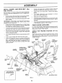
INSTALL
MOWER
AND
DRIVE
BELT
(See
o
Figs. 6 and 24)
-
Be sure tractor is on level surface and mower suspension
arms are raised with attachment lift control Engage parking brake
Connect anti-sway bar to chassis bracket under left
footrest and retain with double loop retainer spring,.
Install clutch rod in clutch level. Secure with retainer
spring
°
Turn height adjustment knob clockwise
slack from mower suspension,
to remove
o
Cut and remove ties securing anti-sway bar and belts,
Swing anti-sway bar to left side of mower deck_
o
Raise deck to highest position.,
,
Slide mower under tractorwith discharge guard to right
side of tractor,
o
IMPORTANT: CHECK BELT FOR PROPER ROUTING IN
ALL MOWER PULLEY GROOVES. INSTALL BELT INTO
ENGINE PULLEY GROOVE
Assemble gauge wheels as shown using long shoulder
bolts, 318washers, and 3/8-1 6 center locknuts_ Tighten
securely,
-
Adjust gauge wheels before operating mower as shown
in the Operation section of this manual
°
Install one front link in top hole of the LH, front mower
bracket and L H. front suspension bracket. Retain with
two single loop retainer springs as shown_
=
Install second front link in R.Ho front suspension bracket
and retain with single loop retainer spring as shown
For best cutting results, mower should be properly leveled.
See "TO LEVEL MOWER HOUSING" in the Service and
Adjustments section of this manual
o
Slide right side of mower back and instafJ link in top hole
of R,H front mower bracket, Retain with single loop
retainer spring as shown,
CHECK
BELTS
°
Turn height adjustment knob counterclockwise
stops
o
Lower mower linkage with attachment lift control,
°
Place the suspension arms on outward pointing deck
pins, if necessary, rock and raise front of mower to
align deck pins with the holes in suspension arms.
Retain with doub{e loop retainer springs with loops
down as shown=
CHASSIS
BRACKET
DOUBLE LOOP
RETAINER SPRING
(outward pointing
deck pins)
CHECK
until it
MOWER
FOR
LEVELNESS
PROPER
POSITION
OF
ALL
See the figures that are shown for replacing motion, mower
drive, and mower blade drive belts in the Service and
Adjustments section of this manual Verify that the heirs ale
[outed correctly_
CLUTCH
LEVER
RETAINER
SPRING
FRONT
SUSPENSION
BRACKETS
CLUTCH
ROD
SUSPENSION
ARMS
ENGINE
PULLEY
FRONT
LINK
SINGLE
LOOP
RETAINER
SPRINGS
SHOULDER
BOLT
FRONT
MOWER
BRACKET
/
GAUGE
WHEEL
/
3/8 WASHER
3/S-16
CENTER
LOCKNUT
/
DOUBLE LOOP
RETAINER
ANTbSWAY
SPRING
USE PLIERS FOR
RETAINER SPRINGS
BAR
• j:_o .
/
J
/
IDLER
PULLEY
DISCHARGE
FIG. 6
10
GUARD
i
i
.........
n,
'IH' n I
I ,III,,,U,UU,,,II,, I U "
I I
I
OPERATION
,u u ,n,u,,m,,,
These
symbols may appear
,,,,
,,
,i,
,...................................
on your tractor or in literature supplied with the produgt.
Learn and understand
their meaning,
BATTERY
CAUTION OR
WARNING
REVERSE
FORWARD
FAST
SLOW
ENGINE ON
ENGINE OFF
OIL PRESSURE
CLUTCH
LIGHTS ON
LIGHTS OFF
MOWER HEIGHT
DIFFERENTIAL
LOCK
PARKING BRAKE
LOCKED
UNLOCKED
\
FUEL
CHOKE
REVERSE
MOWER LIFT
NELITRAL
ATTACHMENT
CLUTCH ENGAGED
HIGH
LOW
ATTACHMENT
CLUTCH DISENGAGED
PARKING BRAKE
IGNITION
HYDROSTATIC FREE WHEEL
(Hydro Models only)
DANGER, KEEP HANDS AND FEET AWAY
11
READ THIS OWNER'S
MANUAL
AND SAFETY
RULES
BEFORE
OPERATING
YOUR TRACTOR
Compare the illustrations with your tractor to familiarize yourself with the locations of various controls and adjustment&
this manual for future reference,
ATTACH MENT
CLUTCH LEVER
Save
LIGHT SWITCH
IGNITION
SWITCH
AMMETER
THROTTLE
CONTROL
ATTACHMENT
LEVER
CLUTCH/BRAKE
PEDAL
PARKING
BRAKE
HEIGHT
ADJUSTMENT
KNOB
GEARSHIFT
LEVER
FIG. 7
Our tractors conform to the safety standards of the American National Standards Institute.
t.
ATTACHMENT CLUTCH LEVER: Used to engage the
mower blades, cr other attachments mounted to your
tractor.
LIGHT SWITCH:
THROTTLE
GEARSHIFT LEVER: Selects the speed and direction of
tractor_
ATTACHMENT LIFT LEVER; Used to raise and Iowe[ the
mower deck or other attachments mounted to your tractor
Turns the headlights on and off.
CONTROL:
CHOKE CONTROL:
Used to control engine speed_
Used when starting a cold engine.
CLUTCH/BRAKE PEDAL: Usedfordectutching
ing the tractor and starting the engine.
PARKING BRAKE:
brake pos{tion.
LIFT LEVER PLUNGER: Used to release attachment lift
lever when changing its position,
IGNITION SWITCH:
engine.
and brak_
Used for starting and stopping the
HEIGHT ADJUSTMENT KNOB: Used to adjust the mower
cutting heighL
Locks clutch/brake pedal into the
AMMETER:
(-)
12
Indicates battery charging (+) c)r discharging
OPERATION
Jt,Ju_
The operation of any tractor can result in foreign objects thPown into the eyes, which can result
in severe eye damage. Always wear safety glasses or eye shields while operating your tractor
or performing any adjustments or repairs. We recommend a wide vision safety mask over the
spectacles or standard safety glasses.
lUl ii
HOW TO USE YOUR TRACTOR
TO USE THROTTLE
TO SET PARKING
Always operate engine at full throttle_
o Operating engine at less than full throttle reduces the
battery charging rate,,
o Fuii throttle offers the best bagging and mower perfor+
mance+
BRAKE
(See Fig. 8)
Your tractor is equipped with an operator presence
switch. When engine is running, any attempt
operator to leave the seat without first setting the
brake will shut off the engine.
.
Depress clutch/brake pedai into full "BRAKE"
and hold
•
sensing
by the
parking
position
TO USE CHOKE
•
ATTACHMENT CLUTCH LEVER
"ENGAGED"
POSITION
THROTTLE
• "DISENGAGED"
POSITION
HEIGHT ADJUSTMENT
KNOB
(See Fig. 8)
po-
GROUND DRIVE-
-
pedal into ful! "BRAKE" position
position,,
NOTE: Failure to move throttle control to slow (,_,)
position and ailowing engine to idle before stopping may
cause engine to "backfire"_
o
•
Turn ignition key to "OFF" position and remove key.
Always remove key when leaving tractor to prevent
unauthorized use.
g_%,
,_
MOWER
position..
CUTTING
.
Turn knob clockwise (r-l)
.
Turn knob counterclockwise
heighL
HEIGHT
(See
to raise cutting height
(F"_)to
lower cutting
•
The average lawn should be c.ut to approximately 2t/2 inches during the coot season and to over 3 inches
during hot months, For healthier and better looking
lawns, mow often and after moderate growth.
-
For best cutting performance, grass over 6 inches in
height should be mowed twice. Make the first cut
relatively high; the second to desired height+
Never use choke to stop engine,
TO OPERATE
NOTE: Under certain conditions when tractor is standing
idle with the engine running, hot engine exhaust gases may
cause "browning" of grass. To eliminate this possibility,
always stop engine when stopping tractor on grass areas.
__
Move gearshift lever to desired
The cutting height range is approximately 1-1/2" to 4", The
heights are measured from the ground to the blade tip with
the engine not running. These heights are approximate
and may vary depending upon soil conditions, height of
grass and types of grass being mowed,
lever to neutral (N) position.
Move throttle control to slow (._)
o
and
The cutting height is controlled by turning the height
adjustment knob in desired direction°
Move attachment clutch lever to "DISENGAGED"
sition
°
Move gearshift
ENGINE -
Start tractor with clutch/brake pedal depressed
gearshift lever in neutral (N) position
Fig. 8)
MOWER BLADES -
Depress clutch_rake
is controlled by the
,,
TO ADJUST
FIG. 8
o
(See
o
Slowly release clutch/brake pedalto start movement..
IMPORTANT: BRING TRACTOR TO A COMPLETE STOP
BEFORE SHIFTING OR CHANGING GEARS. FAILURE
TO DO SO WILL SHORTEN THE USEFUL LIFE OF YOUR
TRANSAXLE.
LEVER
-
AND BACKWARD
The direction and speed of movement
gearshift lever
PARKING BRAK_
"ENGAGED'"
POSITION
MOTION
STOPPING
(See Fig. 8)
To engage choke control, pull knob ouL Slowly push
knob in to disengage..
TO MOVE FORWARD
Fig. 8)
"DISENGAGED"
POSITION
CLUTCH/BRAKE
PEDAL "DRIVE"
POSITION
CONTROL
(See Fig. 8)
Use choke control whenever you are starting a cold engine
Do not use to start a warm engine.
Place parking brake lever in "ENGAGED" position and
reiease pressure from clutchtbrake pedal Pedal should
remain in "BRAKE" position+ Make sure parking brake
will hold tractor secure.
CHOKE
CONTROL
CONTROL
MOWER
(See Fig. 9)
You r tractor is equipped with an operator presence sensing
switch. Any attempt by the operator to leave the seat with
the engine running and the attachment clutch engaged wilt
shut off the engine.
CAUTION" Always stop tractor cornI
pletely, as described above, before leavI
ing the operator's position; to empty
I
ra+._ss.??t+€+h
e?, etc+__.................................... J
'13
o
o
Select desired height of cut.
Lower mower with attachment lift control.
=
Start mower blades by engaging attachment
control.
clutch
i iii
i ii ........................
OPERATION
...............
o
BEFORE
TO STOP MOWER BLADES - disengage attachment
clutch control.
,,,,,,..
CHECK
, ...,.,
.
without either the entire grass catcher,
CAUTION:
on
mowers Do
so not
equipped,
operate or
the the
mower
discharge guard in place.
, .i .i.ii
i .i.,..i.ii1.111.
ATTACHMENT CLUTCH
LEVER "DISENGAGED"
POSITION
]._L.ul.i
"ENGAGED"
POSITION
HEIGHT
ADJUSTMENT
KNOB
.,,
i.illl,
=
-
.......
•
ATTACHMENT
• LEVER
HIGH POSITION
•
LOW
POSITION
i
STARTING
ENGINE
i ill
THE ENGINE
OIL LEVEL (See Fig. 15)
The engine in your tractor has been shipped, from the
factory, already filled with summer weight oil
Check engine oil with tractor on level ground
Remove oi! fill cap/dipstick and wipe clean, reinsert tile
dipstick and screw cap tight, wait for a few seconds,
remove and read oil revel ff necessary, add oit unfit
"FULL" mark on dipstick is reached. Do not overfill
For cold weather operation you should change oil for
easier starting (See OIL VISCOSITY CHART in the
Customer Responsibilities section of this manual)
To change engine oi!, see the Customer Responsibilities section in this manual.
ADD GASOLINE
o
Fif] fuel tank_ Use fresh, clean, regular unleaded
gasoline with a minimum of 87 octane. (Use of leaded
gasoline will increase carbon and lead oxide deposits
and reduce valve life). Do not mix oil with gasoline.
Purchase fuel in quantities that can be used within 30
days to assure fuel freshness.
IMPORTANT: WHEN OPERATING IN TEMPERATURES
BELOW 32°F(0°C), USE FRESH, CLEAN WINTER GRADE
GASOLINE TO HELP INSURE GOOD COLD WEATHER
STARTING
WARNING:
Experience indicates that atcoho] blended
fuels (called gasohol or using ethanol or methanol) can
attract moisture which leads to separation and formation of
acids during storage. Acidic gas can damage the fuel
system of an engine while in storage. To avoid engine
problems, the fuel system should be emptied before storage of 30 days or longer, Drain the gas tank, start the
engine and iet it run until the fuel lines and carburetor are
empty. Use fresh fuel next season. See Storage Instructions for additional information_ Never use engine or
carburetor cteaner products in the fuel tank or permanent
damage may occur'.
DISCHARGE
GUARD
FIG, 9
TO OPERATE
ON HILLS
i iii ill ill
................
ii
i,ii
not
up or
with slopes greater than 15 and do not
CAUTION: Do
drive
down hills
drive across any slope.
.
Choose the slowest speed before starting up or down
hilts.
.
Avoid stopping or changing speed on hilts_
°
If slowing is necessary,
slower position..
-
if stopping is absolutely necessary, push clutch/brake
pedal quickly to brake position and engage parking
brake.
-
move throttle control lever to
b0.om
Move gearshift lever to 1st gear, Be sure you have
allowed room for tractor to roll slightly as you restart
movemen[
]
-
To restart movement, slowly release parking brake and
crutch/brake pedal.
TO START
o
Make air turns slowly.
Raise attachment
ment lift control
•
When pushing or towing your tractor, be sure gearshift
lever is in neutral (N) position°
°
Do not push or tow tractor at more than five (5) MPH
_k
II
spilled oil orFill
fuel,to Do not store,
gas
spilt
tank
or
use gasoline near an open flame.
ENGINE
(See Fig. 8)
When starting the engine for the first time or if the engine
has run out of fuel, it will take extra cranking time to move
fuel from the tank to the engine.
Depress clutch/brake pedal and set parking brake.
o Place gear shift lever in neutral (N) position.
o Move attachment clutch to "DISENGAGED" position.
.
Move throttle control to fast (,_,) position
°
Pull choke control out for a cold engine start attempL
For a warm engine start attempt the choke control may
not be needed.
TO TRANSPORT
.
CAUTION:
filler neck, Do not overfilL Wipeoffany
loll
_,
lift to highest position with attach-
NOTE: To protect hood from damage when transporting
your tractor on a truck or a trailer, be sure hood is closed
and secured to tractor •. Use an appropriate means of tying
hood to tractor (rope, cord, etc.)..
Note: Before starting, read the warm and cold starting
procedures below.
•
Insertkeyintoign{tionandturnkeyc!ockwiseto"START"
position and release key as soon as engine starts Do
not run starter continuously for more than fifteen seconds per' minute. If the engine does not start after
several attempts, push choke control in, wait a few
minutes and try again tf engine still does not start, pull
the choke control out and retry.
14
OPERATmON
i,i,, unn,,,
n ....
i
.....................
WARM WEATHER STARTlNG (50 ° F and above)
•
When engine starts, slowly push choke control in until
the engine begins to run smoothly, tf the engine starts
to run roughly, pull the choke control out slightly for a
few seconds and then continue to push the control in
slowly.
•
The attachments and ground drive can now be used. If
the engine does not accept the lead, restart the engine
and allow itto warm up for one minute using the choke
as described above.
f
COLD WEATHER STARTING (50 ° F and beFow)
o
When engine starts, slowly push choke control in until
the engine begins to run smoothly_ Continue to push
the choke control in small steps allowing the engine to
accept small changes in speed and load, until the
choke control is fulty in. If the engine starts to run
roughly, pull the choke control out slightly for a few
seconds and then continue to push the control in
slowly. This may require an engine warm-up period
from several seconds to several minutes, depending
on the temperature,,
•
The attachments can be used duringthe engine warmup period and may require the choke control be pulled
out slightly,
NOTE: If at a high altitude (above 3000 feet) or in cold
temperatures (below 32 F) the carburetor fuet mixture may
need to be adjusted for best engine performance. See "TO
ADJUST CARBURETOR" in the Service and Adjustments
section of this manual..
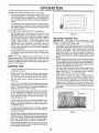
MOWING
MULCHING
Tire chains cannot be used when the mower housing
is attached to tractor.
•
Mower should be properly leveled for best mowing
performance. See "TO LEVEL MOWER HOUSING"
in the Service and Adjustments section of this manual.
The left hand side of mower should be used for
trimming,.
-
Drive so that clippings are discharged onto the area
that has been cut. Have the cut area to the right of the
tractor_ This will result in a more even distribution of
clippings and more uniform cutting
•
When mowing large areas, start by turning to the right
so that clippings will discharge away from shrubs,
fences, driveways, etc After one or two rounds, mow
in the opposite direction making left hand turns until
finished (See Fig.. 10 )
•
If grass is extremely tall, it should be mowed twice to
reduce toad and possible fire hazard from dried
clippings. Make first cut relatively high; the second to
the desired height°
"
Do not mow grass when it is wet.. Wet grass will plug
mower and leave undesirable clumps Allow grass to
dry before mowing.
,
Always operate engine at full throttle when mowing to
assure better mowing performance and proper discharge of material. Regulate ground speed by selecting a low enough gear to give the mower cutting
performance as well as the quality of cut desired.
•
When operating attachments, select a ground speed
that will suit the terrain and give best performance of
the attachment being used°
MOWING
"I"IPS
IMPORTANT:
FOR BEST PERFORMANCE,
KEEP
MOWER HOUSING FREE OF BUILT-UP GRASS AND
TRASH. CLEAN AFTER EACH USE
° The special mulching blade will recut the grass clippings many times and reduce them in size so that as
they falt onto the lawn they will disperse into the grass
and not be noticed. Also, the mulched grass will
biodegrade quickly to provide nutrients for the lawn.
Always mulch with your highest engine (blade) speed
as this will provide the best recutting action of the
blades.
Avoid cutting your lawn when it is weL Wet grass tends
to form clumps and interferes with the mulching action,
The best time to mow your lawn is the early afternoon,
At this time the grass has dried and the newly cut area
will not be exposed to the direct sun
o For best results, adjust the mower cutting height so that
the mower cuts off only the top one-third of the grass
blades (See Fig. 11)., For extremely heavy mulching,
reduce your width of cut and mow sfowly.
o Certain types of grass and grass conditions may require that an area be mulched a second time to
completely hide the clippings., When doing a second
cut, mow across or perpendicular to the first cut path_
o Change your cutting pattern from week to week., Mow
north to s 3uth one week then change to east to west the
next week. This will help prevent matting and graining
of the Fawn.
TiPS
,
°
FIG. 10
MAX 1/3
FIG, 11
15
Check Brake Operation
6##
Check Tire Pressure
6##'
6,/
J7
Check for Loose Fasteners
a
Sharpen/Replace
(_
Lubrication
T
Check Battmy
Level/Recharge
6#1_
0
Clean Battery
and Terminals
61#
R
Check Transaxle
Mower
Blades
e"
_1'4
Chart
6,/
Cooling
e/
64#
Adjust Blade Belt(s) Tension
Adjust Motion Drive Belt(s} Tension
Check Engine
Change
Ott Level
_4
Engine Oi1
_
Clean Air Filter
E
CleanAir
G
Inspect
Replace
I
_"2
Screen
Muffler/Spark
V'
_2.3
_
6/_
v'
Arrester
V; l
iV' l
Oil Filter (If equipped)
C,ea,o
Engine
Coo,h0
ios
Replace
JIv'
Spark Ptug
_
Replace Air FiJter Paper Cartridge
Replace
e/
Fuel Filter
5- It equipped with adjustable system
6- Not _equiredif equippedwith maintenance4ree bette_*y
7 - Tightentrent axle pivotbolt to 35 fblbs maximum
Do not evertighren
1 - Change more often when operating onder e heavy load er in high ambient temperatures
2 oService more ellen when operating _ndkty or dusty cendillons
3 * If equipped with etI filter, change oil avery 50 hours
4 - Reptace blades more often when mowing in sandy soil
GENERAL
LUBRICATION
RECOMMENDATIONS
CHART
The warranty on this tractor does not cover items that have
been subjected to eperato_ abuse or negligence_ To
receive full value from the warranty, operator must maintain
tractor as instructed in this manual
Some adjustments will need to be made periodically to
properly maintain your tractor_
All adjustments in the Service and Adjustments section of
this manual should be checked at least once each season_
,
®
Once a year you should replace the spark plug, clean
or replace air filter, and check blades and belts for
wear. A new spark plug and clean air filter assure
proper air-fuel mixture and help your engine run better
and last longer.
BEFORE
EACH
CLUTCH
PIVOT(S)
USE
*
Check engine oil level.
o
Check brake operation.
o
-
Check tire pressure°
Check for' loose fasteners..
PIVOTS
(_)SAE
30 OR 10W30 MOTOR OIL
®GENERAL
(_)REFER
16
PURPOSE
GREASE
TO CUSTOMER
RESPONSIBILITIES
"ENGINE"
SECTION
IMPORTANT:
DO NOT OIL OR GREASE THE PIVOT POINTS
WHICH HAVE SPECIAL NYLON BEARINGS
VISCOUS LUBRICANTS WtLL ATTRACT
DUST AND DIRT THAT WILL SHORTEN
THE LIFE OF THE SELF-LUBRICATING
BEARINGS.
IF YOU
FEEL THEY MUST BE LUBRICATED,
USE ONLY A DRY, POWDERED GRAPHITE TYPE LUBRICANT
SPARINGLY
==l
= ===
H
.................
= ==H==
TRACTOR
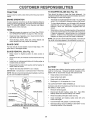
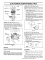
TO SHARPEN
Always observe safety rutes when performing any mainte-
Care should be taken to keep the blade balanced° An
unbalanced blade will cause excessive vibration and eventual damage to mower and engine.
nanceo
BRAKE
OPERATION
If tractor requires more than six (6) feet stopping distance
at high speed in highest gear, then brake must be adjusted_
(See "TO ADJUST BRAKE" in the Service and Adjustments section of this manual),
TIRES
o
Maintain proper air pressure in all tires (See "PRODUCT SPECIFICATIONS" on page 3 of this manual)..
.
Keep tires free of gasoline, oil, or insect control chemicals which can harm rubber.
•
Avoid stumps, stones, deep ruts, sharp objects and
other hazards that may cause tire damage_
BLADE
The blade can be sharpened with a file or on a grinding
wheel. Do not attempt to sharpen while on the mower..
-
To check blade balance, you will need a 5/8" diameter
steel bolt, pin, ora cone balancero (When using a cone
balancer, follow the instructions supplied with balancer) o
o
Slide blade on to an unthreaded portion of the steel bolt
or pin and hold the bolt or pin parallel with the ground.
If blade is balanced, it should remain in a horizontal
position. If either end of the blade moves downward,
sharpen the heavy end until the blade is balanced,
NOTE: Do not use a nail for balancing blade. The lobes of
the center hole may appear to be centered, but are not.
CENTER
For best results mower blades must be kept sharp
place bent or damaged blades.
REMOVAL
(See
Fig.
HOLE
Re-
12)
°
Raise mower to highest position to allow access to
blades,,
o
Remove hex bolt, lock washer and flat washer securing
blade
o
Install new or resharpened blade with trailing edge up
towards deck as shown..
o
Reassemble hex bolt, lock washer and flat washer in
exact order as shown
BLADE
5t8" BOLT
OR PIN
FIG. 13
BATTERY
.
Tighten bolt securely (30-35 Ft. Lbs torque),.
IMPORTANT: BLADE BOLT IS GRADE 8 HEATTREATED
Your tractor has a battery charging system which is sufficient for normal use However, periodic charging of the
battery with an automotive charger will extend its life
NOTE: We do not recommend sharpening blade- but if you
do, be sure the blade is balanced..
BLADE
(See Fig. 13)
o
CARE
BLADE
BLADE
MANDREL
•
Keep battery and terminals cfean_
•
Keep battery bolts tight.
•
Keep small vent holes open.
°
Recharge at 6-10 amperes for 1 hour
TO CLEAN BATTERY AND TERMINALS
Corrosion and dirt on the battery and terminals can cause
the battery to "leak" power.
TRAILING
HEXBOLT
LocKFLAT
WASHER
(GRADE
EDGE
.
Remove terminal guard_
o
Disconnect BLACK battery cable first then RED
battery cable and remove battery from tractor.
o
Rinse the battery with plain water and dry°
•
Clean terminals and battery cable ends with wire
brush until bright.
o
Coat terminals with grease or petroleum jelly°
.
Reinstall battery (See "CONNECT
Assembly section of this manual).
!
*A GRADE 8 HEAT TREATED BOLT CAN BE
IDENTIFIED BYS|XLINES
ONTHEBOLTHEAD_
FIG. 12
17
BATTERY" in the
=!n
................
n,,u
CUSTOME
,,,,,,,
RESPON
= n= ,n,,,,
11 mn
BILITHES
= u,=,,,,,,
in= H,,
= = ,,,,,,
V-BELTS
AIR
Check V_belts for deterioration and wear after 100 hours of
operation and replace if necessary. The belts are not
adjustable, Replace belts if they begin to slip from wear,
TRANSAXLE
SCREEN
OIL
DRAIN
PLUG
COOLING
Keep transaxle free from buiid-up of dirt and chaff which
can restrict cooling:
OIL FILL
CAPA31PSTSICK
ENGINE
LUBRICATION
FIG. 15
Only use high quality detergent oi{ rated with API service
classification SForSG Setecttheoit's SAEviscositygrade
according to your expected operating temperature.
sA__EE
W__SCOSITY
GRACES
_F,
"20_
TEMPERATURE
0"
30"
32 °
40 _
RANGE ANTICIPATED
60_
CLEAN
..............
80 '_
AIR SCREEN
(See Fig. 15)
Air screen must be kept free of dirt and chaff to prevent
engine damage from overheating. Clean with a wire brush
or compressed air to _emove dirt and stubborn dried gum
fibers.
AIR FILTER (See Fig. 16)
100°
Your engine wit] not run properly using a dirty air filter.
Clean the foam pre-cleaner after every 25 hours of operation or every season. Service paper cartridge every 100
hours of operation or every season, whichever occurs first
BEFORE NEXT OIL CHANGE
FIG. 14
NOTE: Although multi-viscosity oils (5W30, 10W30 etc)
improve starting in cold weather, these multi-viscosity oils
will result in increased oil consumption when used above
32°F. Check your engine oil level more flequently to avoid
possible engine damage flom running low on oil,
Service air cleaner more often under dusty conditions
=
Remove knob(s) and covet
TO SERVICE PRE-CLEANER
Change the oil after the first two hours of operation and
every 25 hours thereafter or' at least once a year if the
tractor is not used for 25 hours in one year_
o
Slide foam pre-cleaner off cartridge,
,,
Wash it in liquid detergent and water
•
Squeeze it dry in a clean cloth,
Check the crankcase oil level before starting the engine
and after each eight (8) hours of operation, Tighten oil fill
cap/dipstick securely each time you check the oil level°
-
Saturate it in engine oil. Wrap it in clean, absorbent
cloth and squeeze to remove excess oil,.
•
If very dirty or damaged, replace pre-cleaner,
TO CHANGE ENGINE OIL (See Fig 15)
°
Reinstall pre-cleaner over cartridge,
•
Reinstall cover and secure with knob(s),
Determine temperature range expected before oil change
Atl oil must meet API service classification SF or SG
TO SERVICE CARTRIDGE
-
Be sure tractor is on level surface.
.
Remove wing nuts and cartridge plate,
o
Oil will drain more freely when warm
-
.
Catch oif in a suitable container.
Carefully remove cartridge
entering carburetor.
•
Remove oil fill cap/dipsticko Be careful not to allow dirt
to enter the engine when changing oil,
o
Clean cartridge by tapping gently on fiat surface
dirty or damaged, replace cartridge
.
Remove drain plug.
•
After oil has drained completely, replace oil drain plug
and tighter_ securely.
.
Refill engine with oil through oil fitl dipstick tube. Pour
slowly. Do not overfill. For approximate capacity see
"PRODUCT SPECIFICATIONS"
on page 3 of this
manual,.
•
Use gauge on oil fill cap/dipstick for checking level Be
sure dipstick cap is tightened securely for accurate
reading Keep oil at "FULL" line on dipstick.
o
to prevent debris from
If very
ReinstaLl cartridge plate, wing nuts, precteaner, cover
and secure with knob(s).
IMPORTANT:
PETROLEUM SOLVENTS, SUCH AS
KEROSENE, ARE NOT TO BE USED TO CLEAN THE
CARTRIDGE THEY MAY CAUSE DETERIORATION OF
THE CARTRIDGE. DO NOT OiL CARTRIDGE, DO NOT
USE PRESSURIZED
AIR TO CLEAN
OR DRY
CARTRIDGE
18
CUSTOMER
RESPONSDBULNTIES
,
/
ENGINE
COVER
i
OIL FILTER (See Fig. 18)
Replace the engine oil filter every season or every other oi[
change if the tractor is used more than 100 hours in one
year.
PLATE
=
Unscrew old filter by turning counterclockwise.
suitable container to catch oil.
•
Apply a thin coating of new engine oil to rubber gasket
on replacement oil filter.
Install replacement oil filter by turning clockwise until
rubber gasket contacts mounting surface, then tighten
filter an additional 1/2 to 3/4 turn.
FOAM
o
AIR SCREEN
CARTRIDGE
o
o
FIG, 16
ENGINE
COOLING
Use a
Fill crankcase with new oil (See "TO CHANGE ENGINE OIL" in this section of this manual). For approximate capacity see "PRODUCT SPECIFICATIONS" on
page 3 of this manual.
Start engine and check for oil leaks. Correct any leaks
before placing engine into full operation
FINS (See Fig. 17)
OIL FILTER
Remove any dust, dirt or oil from engine cooling fir_ to
prevent engine damage from overheating. Air guide c(..ers
must be removed, Remove side panels and hood (See "TO
REMOVE HOOD AND GRILL ASSEMBLY" in the Service
and Adjustments section of this manual).
TOP AIR
GUIDE COVE
FIG. 18
IN-LINE
ENGINE
COOLING
FUEL
FILTER
(See Fig. 19)
The fuel filter should be replaced once each season If fuel
filter becomes clogged, obstructing fuel flow to carburetor,
replacement is required,,
FINS
o
=
o
-
With engine cool, remove filter and plug fue{ line
sections.
Place new fuel filter in position in fuel !ine with arrow
pointing towards carburetor.
Be sure there are no fuel line leaks and clamps are
properly positioned°
lmmediatetywipe up any spi{led gasoline.
AIR GUIDE COVER (BOTH SIDES)
CLA_LAMP
FIGo 17
FUEL
/
FILTER _
\
//
_-""_-_-----J
/
_d
MUFFLER
FIG. 19
Inspect and replace corroded muffler and spark arrester (if
equipped) as it could create a fire hazard and/or damage
CLEANING
SPARK
o
Clean engine, battery, seat, finish, etc of all foreign
matter
-
Keep finished surfaces and wheels free of al! gasoline,
oil, etc.
-
Protect painted surfaces with automotive type wax
PLUGS
Replace spark plugs at the beginning of each mowing
season or after every 100 hours of operation, whichever
occurs first. Spark plug type and gap setting are shown in
"PRODUCT SPECIFICATIONS" on page 3 of this manual.
19
We do not recommend using a garden hose to clean your
tractor unless the electrical system, muffler, air filter and
carburetor are covered to keep water out Water in engine
can result in a shortened engine life
CAUTION:BEFORE
PERFORMING ANY SERVICE OR ADJUSTMENTS:
Depress clutch/brake pedal fully and set parking brake,
Place gearshift lever in neutral (N) position.
Place attachment clutch in "DISENGAGED"
position.
Turn ignition key "OFF" and remove key,
Make sure the blades and all moving parts have completely stopped.
Disconnect spark plug wire from spark plug and place wire where it cannot come in contact
with plug=
o
o
o
i,i ,,11iii
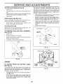
TO REMOVE
.............
MOWER
(See Fig. 20)
°
o
Place attachment clutch in "DISENGAGED"
position°
,
Turn height adjustment knob to lowest setting.
o
Lower mower to its lowest position
,
Disconnect clutch rod from clutch lever by removing
retainer spring,
=
Remove retainer spring holding anti-swayba_ to chassis bracket and disengage anti-swaybar from bracket
Slide mower out from under right side of tractor.
IMPORTANT: tFAN ATTACHMENT OTHER THAN THE
MOWER DECK 1STO BE MOUNTED ON THE TRACTOR,
REMOVE THE FRONT LINKS.
•
Remove retainer springs from suspension
deck and disengage arms from deck
•
Raise attachment lift to its highest position.
•
Remove two retainer' springs from each front link and
remove links.
TO INSTALL
MOWER
FOllow procedure described in 'qNSTALL MOWER AND
DRIVE BELT" in the Assembly section of this manual
arms at
CLUTCH
LEVER
SUSPENSION
ARMS
Slide mower forward and remove belt from engine
pulley.
RETAINER
SPRING
FRONT
SUSPENSION
BRACKET
CLUTCH
ROD
ADJUSTMENT
NUTS
ENGINE
PULLEY
LIFT
LINKS
CHASSIS
BRACKET
LINKS
RETAINER
- SPRINGS
FRONT MOWER
BRACKET
RETAINER
SPRING
ANTI-SWAY
BAR
RETAINER
SPRINGS
FIG. 20
2O
SE
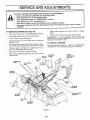
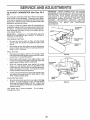
TO LEVEL
MOWER
CE AN
ADJUSTMENTS
HOUSING
FRONT-TO-BACK ADJUSTMENT (See Figs., 23 and 24)
IMPORTANT: DECK MUST BE LEVEL SIDE-TO-SIDE. IF
THE FOLLOWING FRONT-TO-BACK ADJUSTMENT lS
NECESSARY, BE SURE TO ADJUST BOTH FRONT LINKS
EQUALLY SO MOWER WILL STAY LEVEL SIDE-TOSIDE..
Adjust the mower while tractor is parked on level ground or
driveway.
Make sure tires are properly inflated (See
"PRODUCT SPECIFICATIONS" on page 3 of this manual).
If tires are over or underinflated, you will not properly adjust
your mower..
To obtain the best cutting results, the mower housing
should be adjusted so that the front is approximately 1/8" to
1/2" lower than the rear when the mower is in its highest
position.
SIDE-TO-SIDE ADJUSTMENT (See Figs 2t and 22)
o
Raise mower to its highest position.
o
At the midpoint of both sides of mower, measure height
from bottom edge of mower to ground. Distance "A" on
both sides of mower should be the same or within I/4"
of each other.
o
If adjustment is necessary, make adjustment on one
side of mower only..
o
To raise one side of mower, tighten lift link adjustment
nut on that side.
o
To lower one side of mower, loosen lift link adjustment
nut on that side
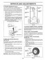
Check adjustment on right side of tractor. Measure distance"D" directly in front and behind the mandrel at bottom
edge of mower housing as shown_
o Before making any necessary adjustments, check that
both front links are equal in length Both links should
be approximately 10-3/8"
°
If links are not equal in length, adjust one link to same
length as other link..
•
To lower front of mower loosen nut "E" on both front
links an equal number of turns
•
When distance "D" is 1/8" to 1/2" lower at front than
rear, tighten nuts "F" against trunnion on both front
links..
o To raise front of mower, loosen nut"F" from trunnion on
both front links. Tighten nut "E" on both front links an
equal number of turns.
o When distance "D" is 1/8" to 1/2" lower at front than
rear, tighten nut"F" against trunnion on both front links.
o Recheck side-to-side adjustment°
NOTE: Each full turn of adjustment nut will change mower
height about 1/8".
.
Recheck measurements
after adjusting.
BOTTOM EDGE
OF MOWER TO
GROUND
BOTTOM EDGE
OF MOWER TO
GROUND
,',:,, ':_o
GROUND LINE
,
,t
MANDREL
FIG. 21
SUSPENSION
ARM
FIG. 23
BOTH FRONT LINKS MUST BE EQUAL IN LENGTH
LIFT LINK
ADJUSTMENT
NUT
FIG. 22
NUT "E"
NUT "F"
FRONT LINKS
21
TRUNNION
FIG. 24
..................
H'm'H"
'1==
I
I
== ,,,
I
I'
ADJUST IENTS
...........
i i m,.,ll ......................
n
11, mn,
n, ,,
.....................
MOWER DRIVE BELT REMOVAL (See Fig_ 25)
TO REPLACE
(See Fig. 26)
•
Park the tractor on level surface_ Engage parking brake°
TO REPLACE
•
MOWER
DRIVE BELT
Park tractor on a level surface. Engage parking brake.
Disengage attachment crutch contro}
Remove four screws from L.H. mandrel cover and
remove cover.
•
Roll belt over the top of L_H. mandrel pulley.
,
Remove belt from engine puttey_
o
Remove belt from idler pulleys.
°
Remove any dirt or' grass clippings which may have
accumulated around mandrels and entire upper deck
surface.
MOWER
BLADE
DRIVE
BELT
•
Remove mower drive belt (See'TO REPLACE MOWER
DRIVE BELT" in this section of this manua!).
=
Remove mower (See "TO REMOVE MOWER" in this
section of this manual)°
Remove four screws from R H. mandrel cover and
remove cover
.
=
Disconnect secondary clutch rod from pivot rod by
removing retainer spring.
o
Carefully roll belt off R H. mandrel pulley°
Check primary idler arm and two idlers to see that they
rotate freely.
°
Remove belt from center mandrel pulley, idler pulley,
and L.H mandrel pulley
MOWER DRIVE BELT INSTALLATION (See Fig. 25) o
Install belt in both idlers. Make sure belt is in both belt
keepers at the idlers as shown..
.
Remove any dirt or grass which may have accumulated around mandrels and entire upper deck surfacer
=
Check secondary idler arm and idler to see that they
rotate freely
=
Be sure spring is hooked in secondary idler arm and
sway-bar bracket.
.
Install new belt in lower groove of L H mandrel pulley,
idler pulley, and center mandrel pulley as shown.
-
Roll belt over R_H mandrel pulley Make sure bett is in
all grooves properly.
-
Reconnect secondary
retainer springy
•
Reinstall RHo mandrel cover
•
Reinstall mower to tractor (See "INSTALL MOWER
AND DRIVE BELT" in the Assembly section of this
manual)
•
Reassemble mower drive belt (See "TO REPLACE
MOWER DRWE BELT" in this section of this manua0_
=
,
Install new be_t onto engine pulley.
o
Rolt belt into upper groove of L°H. mandrel pulley_
°
Carefully check belt routing making sure belt is in the
grooves correctly and inside belt keepers.
Reassemble L.H. mandrel cover.
o
SCREWS
%RELA
IDLER
PULLEYS
ENGINE
PULLEY
LH. MANDREL
clutch rod to pivot rod with
MOWER
BLADE
DRIVE BELT
CENTER
MANDREL
SECONDARY
IDLER ARM
LI
MANDREL
SPRING
MOWER
DRIVE
BELT
BELT
KEEPERS
FIG_ 25
SWAYBAR
BRACKET
IDLER
PULLEY
FIG. 26
22
SCREW
SERVICE
TO ADJUST
ID ADJUSTMENTS
(See Fig. 27)
BRAKE
PULLEY
Your tractor is equipped with an adjustable brake system
which is mounted on the right side of the transaxle.
IDLER
If tractor requires more than six (6) feet stopping distance
at high speed in highest gear, then brake must be adjusted
o
Depress clutch/brake pedal and engage parking brake
•
Measure distance between brake operating arm and
nut "A" on brake rod
_LOCATOR
TABS
BELT
KEEPER
IDLER
If distance is other than 1-1/2", loosen jam nut and turn
nut "A" until distance becomes 1-1/2". Retighten jam
nut against nut "A"_
Road test tractor for proper stopping distance as stated
above, Readjust if necessary, If stopping distance is
stilt greater than six (6) feet in highest gear, further
maintenance is necessary_ Contact your nearest authorized service center/department.
WITH PARKING
PULLEY
BRAKE "ENGAGED"
FIG_ 28
TO ADJUST
STEERING
WHEEL
ALIGNMENT
NUT "A"
If steering wheel crossbars are not horizontal (left to right)
when wheels are positioned straight forward, remove steering wheel and reassemble per instructions in the Assembly
section of this manual
JAM NUT
OPERATING
FRONT WHEEL
The front wheel toe.in and camber are not adjustable on
your tractor, if damage has occurred to affect the front
wheel toeqn or camber, contact your nearest authorized
service center/department.
ARM
TO REMOVE WHEEL
(See Fig. 29)
FIG. 27
TO REPLACE
(See
Fig.
MOTION
DRIVE
TOE-IN/CAMBER
.
o
BELT
28)
Park the tractor on level surface. Engage parking brake.
For assistance, there is a belt installation guide decal on
bottom side of ]eft footresL
,
•
.
Remove mower (See "TO REMOVE MOWER" in this
section of this manuaL)
°
.
Remove upper belt keeper1
o
•
•
Remove belt from stationary idler and clutching idler,
Puff belt slack toward rear of tractor, Remove belt
upwards from transaxle pulley by deflecting belt keepers.
•
Pull belt toward front of tractor and remove downwards
from around engine pulley.
FOR REPAIRS
B]ock up axle securely.
Remove axle cover, retaining ring and washers to allow
wheel removal (rear wheel contains a square key- Do
not Iose)_
Repair tire and reassemble_
On rear wheels only: align grooves in rear wheel hub
and axte. Insert square key
Replace washers and snap retaining ring securely in
axle groove,
Replace axle cover.
WASHERS
RETAINING
RING
.
Install new belt by reversing above procedure,
IMPORTANT:
MAKE SURE UPPER BELT KEEPER IS
POSITIONED PROPERLY BETWEEN LOCATER TABS
AXLECOVER
'_I_SQUAREKEY
(REAR WHEELONLY)
23
FIG, 29
SERVmC
i, i i, ii
,, i,,,i
,,,i .........................................
TRANSAXLE
SHIFTER
LINKAGE
JUSTMENT (See Figs. 30 and 31)
AND
TO START ENGINE WITH A WEAK BATTERY
AD-
(See Fig. 32)
....................
The transaxle should be in neutral when the gear shift lever
is in the neutral (N) (lock gate) position The adjustment is
preset at the factory; however, if adjustment is needed,
proceed as follows:
°
•
Make sure transaxte is in neutral (N),
Loosen two Iocknuts on tie rod.
,
Turn center rod unti! gearshift lever falls into neutral
lock gate on fender console_
,
Tighten locknuts securely.
&
iii
,H
,,111
NI
i llll
ll,ll
!l
CAUTION: Lead-acid batteries generate explosive gases. Keep sparks,flame
and smoking materials away from batteries,
Always wear eye protection
when around batteries.
ii ,,i i,iii i,
,H,,,,,,,
i,
If your battery is too weak to start the engine, it should be
recharged.
If "jumper cables" are used for emergency
starting, follow this procedure:
IMPORTANT:
YOUR TRACTOR
IS EQUIPPED
WiTH A
12 VOLT NEGATIVE GROUNDED
SYSTEM. THE OTHER
VEHICLE
MUST ALSO
BE A 12 VOLT
NEGATIVE
GROUNDED
SYSTEM,
DO NOT USE YOUR TRACTOR
BATTERY TO START OTHER VEHICLES,,
LEVER
rRAL
LOCK GATE
TO ATTACH JUMPER CABLES .
o
,
FIG. 30
Connect each end of the RED cable to the POSITIVE
(+) terminal of each battery, taking care not to short
against chassis,
Connect one end of the BLACK cable to the NEGATiVE (-) terminal of fully charged battery,
Connect the other end of the BLACK cable to good
CHASSIS GROUND, away from fuel tank and battery
TO REMOVE CABLES, REVERSE ORDER o
BLACK cabfe first from chassis and then from the fully
charged battery
RED cable last from both batteries.
"POSITIVE"
(+)
"NEGATIVE"(=)
ii
_(_
TRANSAXLE
L H, PANE:
11
;OL,
,
FIG, 31
FIG. 32
24
/
SERVICE AN
TO REPLACE
HEADLIGHT
ADJUSTMENTS
BULB
TO ADJUST
•
Raise hood,
o
Pull bulb holder out of the hole in the backside of the
grill.
•
Replace bulb in holder and push bulb holder securely
back into the hole in the backside of the grill
Close hood,
°
INTERLOCKS
.
Remove air cleaner cover, filter and cartridge plate to
expose carburetor choke (see "AIR FILTER" in the
Customer Responsibilities section of this manual),
o
Choke should be closed. If it is not, loosen casing
clamp screw and move choke cable until choke is
compIetety closed Tighten casing clamp screw securely.
Reassemble air cleaner
o
FUSE
Replace with 30 amp automotiveqype plug-in fuse
fuse holder is located behind the dash
TO REMOVE
HOOD
AND
GRILL
(See Fig. 35)
With engine not running, move choke control (located
on dash panel) to full choke (N) position.
Check wiring. See electrical wiring diagram in the
Repair Parts section of this manual
TO REPLACE
CONTROL
°
AND RELAYS
Loose or damaged wiring may cause your tractor to run
poorly, stop running, or prevent it from starting
o
CHOKE
The choke control has been preset at the factory and
adjustment should not be necessary, Check adjustment as
described below before loosening cable. If adjustment is
necessary, proceed as foIlows:
The
CLAMP SCREW
ASSEMBLY
(See Fig. 33)
o
Raise hood,
•
Unsnap headlight wire connector.
°
Standinfrontoftractor.
Grasphoodatsides,
engine and lift off of tractor,
°
To replace, reverse above procedures.
titttoward
HOOD
/
SWIVEL
l
" "
_"
FIG. 34
WIRE
HEADLIGHT
CONNECTOR
CHOKECLOSED_
FIG. 33
ENGINE
TO ADJUST THROTTLE
(See Fig. 34)
LEVER
CONTROL
CABLE
CLAMP
SCREW
The throttte contro! has been preset at the factory and
adjustment should not be necessary. Check adjustment as
described below before loosening cable. If adjustment is
necessary, proceed as follows:
=
With engine not running, move throttle control lever to
fast (,_) position.
•
Check that swivel is against side of quarter circle. If it
is not, loosen cabte clamp screw and pull cable back
until swivef is against quarter circle. Tighten cabie
clamp screw securely
25
TO ADJUST
37)
CARBURETOR
IMPORTANT:
NEVER TAMPER
WITH THE ENGINE
GOVERNOR,
WHICH IS FACTORY
SET FOR PROPER
ENGINE SPEED, OVERSPEEDING
THE ENGINE ABOVE
THE FACTORY
HIGH
SPEED
SETTING
CAN BE
DANGEROUS
tF YOU THINK THE ENGINE-GOVERNED
HiGH SPEED NEEDS ADJUSTING,
CONTACT
YOUR
NEAREST
AUTHORIZED
SERVICE
CENTER/
DEPARTMENT,
WHICH HAS PROPER EQUIPMENT AND
EXPERIENCE
TO
MAKE
ANY
NECESSARY
ADJUSTMENTS,
(See Figs. 36 &
The carburetor' has been preset at the factory and adjustment should not be necessary, However, minor adjustment may be req uired to compensate for differences in fuel,
temperature, altitude or toado If the carburetor' does need
adjustment, proceed as follows:
In general, turning the mixture screw in (clockwise) decreases the supply of fuel to the engine giving a leaner fuel!
air mixture Turning the mixture screw out (counterclockwise) increases the supply of fuel to the engine giving a
richer' fuel/air mixture_
IMPORTANT:
DAMAGE TO THE NEEDLES AND THE
SEATS IN CARBURETOR MAY RESULT 1F SCREW IS
TURNED IN TOO TIGHT
PRELIMINARY
•
•
IDLE SPEED
SCREW
IDLE MIXTURE
SCREW
SETTING -
Be sure you have a clean air filter, and the throttle
control cable and choke are adjusted properly (see
above)
THROTTLE
LEVER
With engine off turn idle mixture screw in (clockwise)
closing it finger tight and then turn out (counterclockwise) 1-1/4 to 1-1/2 turns
FINAL SETTING •
o
Start engine and allow to warm for five minutes. Make
final adjustments with engine running and shift/motion
control lever in neutral (N) position.
With throttle control lever in slow (,_,) position, hold
throttle lever against idle speed screw and adjust idle
speed screw to obtain 1200 to 1400 RPM.
•
While still holding throttle lever against idle speed
screw, turn idle mixture screw in (clockwise) until
engine begins to die and then turn out (counterclockwise) until engine runs rough. Turn screw to a point
midway between those two positions
•
Continue to hold throttle lever against idle speed screw
and adjust idle speed screw to obtain 900 to 1200
RPM Release throttle lever.
ACCELERATION
,
FIG. 36
THROTTLE
LEVER
TEST-
Move throttle control lever from slow (,_=,) to fast (,_)
position If engine hesitates or dies, turn idle mixture
screw out (counterclockwise) 1/8 turn, Repeat test
and continue to adjust, if necessary, until engine accelerates smoothly.
High speed stop is factory adjusted
damage may result
IDLE MIXTURE
SCREW
FIG. 37
Do not adjust -
26
ENGRNE
Immediately prepare your tractor for storage at the end of
the season or if the tractor will not be used for 30 days or
more.
FUEL SYSTEM
IMPORTANT:
IT tS IMPORTANT
TO PREVENT
GUM
DEPOSITS
FROM
FORMING
IN ESSENTIAL
FUEL
SYSTEM PARTS SUCH AS CARBURETOR,
FUEL FILTER,
FUEL HOSE, OR TANK DURING
STORAGE.
ALSO,
EXPERIENCE
INDICATES
THAT ALCOHOL
BLENDED
FUELS (CALLED
GASOHOL
OR USING ETHANOL
OR
METHANOL)
CAN ATTRACT MOISTURE
WHICH LEADS
TO SEPARATION
AND FORMATION
OF ACIDS DURING
STORAGE.
ACIDIC
GAS CAN DAMAGE
THE FUEL
SYSTEM OF AN ENGINE WHILE IN STORAGE
gasoline in the tank inside a building
where
fumesNever
may store
reachthe
an tractor
open flame
CAUTION:
with
or spark.
Allow the engine to cool
before storing in any enclosure.
TRACTOR
Remove mower from tractor for winter storage,. When
mower is to be stored for a period of time, clean it thoroughly, remove all dirt, grease, leaves, etc. Store in a
clean, dry area..
•
Clean entire tractor (See "CLEANING" in the Customer
Responsibilities section of this manual).
o
Inspect and replace belts, if necessary (See belt replacement instructions in the Service and Adiustments
section of this manual)_
o
Lubricate as shown in the Customer Responsibi
section of this manual.
o
Be sure that all nuts, bolts and screws are securely
fastened, Inspect moving parts for damage, breakage
and wear. Replace if necessary.
o
Touch up all rusted or chipped paint surfaces; sand
lightly before painting,
,
Drain the fuel tank_
•
Start the engine and let it run until the fuel lines and
carburetor are empty.
o
Never use engine or carburetor cleaner products
fuel tank or permanent
damage may occur
o
Use fresh fuel next season,
in the
NOTE: Fuel stabilizer is an acceptable alternative in
minimizing the formation of fuel gum deposits during storage. Add stabilizer to gasoline in fuel tank or storage
container. Always follow the mix ratio found on stabilizer
container
Run engine at least 10 minutes after adding
stabilizer to allow the stabilizer to reach the carburetor. Do
not drain the gas tank and carburetor if using fuel stabilizer
_es
ENGINE
OIL
Drain oil (with engine warm) and replace with clean engine
oil. (See "ENGINE" in the Customer Responsibilities
section of this manual).
BATTERY
°
Fully charge the battery for storage.
•
After a period of time in storage, battery may require
recharging,
•
Remove spark plug(s)o
•
To help prevent corrosion and power leakage during
long periods of storage, battery cables should be
disconnected and battery cleaned thoroughly (see "TO
CLEAN BATTERY AND TERMINALS" in the Customer Responsibilities section of this manual)°
•
Pour one ounce of oil through spark plug hole(s) into
cylinder(s)
,
Turn ignition key to"START" position for a few seconds
to distribute oil
After cleaning, leave cables disconnected and place
cables where they cannot come in contact with batter:/
terminals.
.
Replace with new spark plug(s)
•
Be sure battery drain tube is securely attached.
°
Do not store gasoline from one season to another
•
If battery is removed from tractor for storage, do not
store battery directly on concrete or damp surface&.
*
Replace your gasoline can if your can starts to rust.
Rust and/or dirt in your gasoline will cause problems°
°
If possible, store your tractor indoors and cover it to
give protection from dust and dirt
•
CYLINDERS
OTHER
o
Cover your tractor with a suitable protective cover that
does not retain moisture, Do not use plastic. Plastic
cannot breathe which allows condensation to form and
will cause your tractor to rust.
IMPORTANT: NEVER COVER TRACTOR WHILE ENGINE
AND EXHAUST AREAS ARE STILL WARM
27
TRO
CAUSE
PROBLEM
ii
,H,I
II1,1,1 ¸
Will not start
1,
Out offuef
2
3
4
5
6
7.
Engine not"CHOKED"
Engine fiooded.
Bad spark plug
Dirty air filter
Dirty fuel fifter
Water in rue!
8
9
Loose or damaged wiring
Carburetor out of adjustment
10
1.
2
3
4
5
6
7
property.
8
9
10
Engine valves out of adjustment,
i in,,n
in,,,,n
i
Fill fuel tank
See "TO START ENGINE" in Operation section
Wait several minutes before attempting to start
Replace spark plug
Clean/replace air filter,
Replace fuel filter
Drain fuel tank and carburetor, relill tank with fresh
gasoline and replace fuel filter,
Check all wiring.
See "To Adjust Carbufeto¢' in Service Adjustments
section
Contact an authorized service center/department
n lnnnnn,l,,,,
1
2
3
4
5
6
7
Dirty air filter
Bad spark plug
Weak or dead battery
Dirty fuel filter
Stale or dirty fuel
Loose or damaged wiring
Carburetor out of adjustment
1
2
3
4
5
6
7
8
Engine valves out of adjustment
8
Clean/replace air filter
Replace spark plug
Recharge or replace battery
Replace fuel filter
Drain fuel tank and refill with fresh gasoline
Check all wiring.
See "To Adjust Carburetor" in Service Adjustments
section
Contact an authorized service center/department
1
2
3
4
5
6
7
8
9
Clutch!brake pedal not depressed
Attachment clutch is engaged,
Weak or dead battery,
Blown fuse
Corroded battery terminals
Loose or damaged wiring
Faulty ignition switch.
Faufly solenoid or starter
Faulfy operator presence switch(es)
t
2
3
4.
5
6
7
8
9
Depress clulchibrake pedal
Disengage attachment clutch
Recharge or replace battery
Replace fuse
Clean battery terminals
Check all wiring
Check!replace ignition switch
Check/replace solenoid or starter
Confact an authorized service center/department
Engine clicks but will not
start
1
2
3
4
Weak or dead battery,
Corroded battery terminals
Loose or damaged wiring
Faulty solenoid or starter
1
2
3
4,
Recharge or replace battery
Clean battery terminals
Check all wiring
ChecWreplace solenoid or starter
Loss of power
1
2
3
4
5,
6
7
8
9
Cutting too much grass/too fast
Throttle in "CHOKE" position.
Build=up of grass, leaves and trash under mower
Dirty air filter.
Low oil levelldirty oiL
Faulty spark plug
Dirty fuel filter
Stale or dirty fuel
Water in fuel
1
2
Set in "Higher Cut" position!reduce speed
Adiust throttle control,.
Clean underside of mower housing
Clean/replace air filter
Check oil level/change oil
Clean and regap or change spark plug
Replace fuel filter,
Drain fuel tank and refill with fresh gasolin&
Drain fuel tank and carburetor, refill tank with fresh
Hard to start
1iLL JLLIUJUU_
I
Engine will not turn over
i
,,u
vibration
4
5
6
7
8
9
10
l I
12
t3
t4
Spark plug wire toose
Dirty engine air screen/fins
Dirty/clogged muffler
Loose or damaged wiring
Carburetor out of adjustment
10
1l
12
13,
14
15.
Engine valves out of adjustment
15
ii
Excessive
3,
1
2
3
gasoline and replace fuel filter
Corrnect and tighten spark plug wire
Clean engine air screen/fins
Clean!replace muffler
Check all wiring.
See 'q'o Adjust Carburetor" in Service Adjustments
section.
Contact an authorized service centerideparlment
iii iiii1,111, ii
1
2
3
Worn, bent or Ioose blade,
Bent blade mandrel
Loose/damaged part(s}
28
Reptace blade Tighten blade bolt
Replace blade mandrel.
Tighten loose part(s) Replace damaged
parts.
POmNTS
TROUIBLESHOOTJNG
PROBLEM
CAUSE
CORRECTION
Engine continues to run
when operator leaves seat
with attachment
clutch
t
Faulty operalor-safety
1
2
3
4
Worn, bent or loose blade
Mower deck notlevel
Buildup of grass, leaves, and trash under mower
Bent blade mandrel
5
Ctogged mower deck vent hotes from buildup of
grass, leaves, and trash around mandrels
Mower blades will not
rotate
1
2
3
4
Obstruction in clutch mechanism
Worn/damaged mower drive bell
Frozen idter pulley
Frozen blade mandret
Poor grass discharge
1
2,
3
4
5,
6.
7
8
Engine speed too slow
Travel speed too fast
Wet grass
Mower deck not level
Low/uneven tire air pressure
Worn, bent or loose blade
Buildup of grass, leaves and |rash under mower
Mower drive belt worn
9
t0
t 1
Blades improperly installed
Improper blades used
Clogged mower deck vent holes from buildup of
grass, leaves, and trash around mandrels
presence control system,
1
Check wiring, switches and connections
If not
corrected, conlact an authorized service center/
department,
1
2
Replace blade Tighten blade bolt
Level mower deck
3
4
5
Clean underside of mower housing
Replace blade mandrel
Clean around mandrels to open vent holes
engaged
Poor cut - uneven
Headlight(s) not working
(if so equipped)
I
Remove obstruction
2
3
4
Reprace mower drive belt
Replace idler pulley
Replace blade mandrel
1
2
3
4
P_ace throttle controt in "FAST" posilion
Shift to slower speed
Aflow grass to dry before mowing
Level mower deck,
5
6
7
8
9
I0
11
Checktires for proper air pressure
Repface/sharpen blade Tighten blade bolt
Clean underside of mower housing
Replace mower drive belt
Reinstall blades sharp edge down,
Replace with blades listed in this manual
Clean around mandrels to open vent holes
1
2
3
4
5
Swifc!_ is "OFF"
Bulb(s) burned out
Faulty light switch
Loose or damaged wiring
Blown fuse
1
Turn switch "ON"
2
3
4
5
Replace bulb(s)
ChecWreplace light switch
Check wiring and connections
Replace fuse
I,
2.
Bad battery cell(s)
Poor cable connections
1
2
Repface battery
ChecWclean all connections
3,
4
Faulty regulator (if so equipped)
Faulty alternator
3
4
Replace regulator
Replace alternator
i,,,,ui.ulul
Battery will not charge
Engine "backfires"
when turning engine
"OFF"
Engine throttle control not set at "SLOW"
position for 30 seconds before stopping engine
29
Move lhrottle control to "SLOW" position and allow
to idle for 30 seconds before stopping engine
3O
TRACTOR
- - MODEL NUMBER
917.258660
SCHEMATIC
BLACK
RED
BATTERY
)
c/'Lp
RED
I
,
+
)
RED
FUSE 30 AMP
AMMETER
(OPTIONAL)
t
t
I
BLACK
I
WHSTE
I
I
i
t
•
I
i
fi_
(PEDALUP)
[
STARTER
WHITE
SEAT SWITCH
IGNITION
SWITCH
k
--,_-
/
(NOT OCCUPIED)
,z--4_- ,zq--,
,,-¢_
-1T--
_
I ¢'_'
r_F---
F
/7
__ BL_CK_ __ _ ___j_A.fCT_MENT CLUTCH"_
"L._
-HO--_METER
__m
(CLUTCHOFF)
!
(OPTIONAL)
" -GR-OUNE_ING-'
j
__oSPARK
B_CK O[
)
CONNECTOR
)
PLUG
)
GAP
0-'-----4
(2 PLUGS ON
TWIN CYL ENGINES)
IGNITION
UNIT
CHARGING SYSTEM OUTPUT
3 AMP DC @ 3600 RPM
26 VOLTS AC M(N. @ 3600 RPM
(CHARGING SYSTEM DISCONNECTED)
t
BLUE
LIGHT)NG
SYSTEM
OUTPUTDIODE
ORANGE
-\
JAL
.....
_4 VOLTS AC MIN
@ 3600 RPM (LIGHTS
J
OFF)
HEADLIGHTS
BROWN
NOTE
YOUR TRACTOR IS
EQUIPPED WITH A SPECIAL
ALTERNATOR SYSTEM,
THE LIGHTS ARE NOT
O
----O--CONNECTED TO THE
NON-REMOVABLE
REMOVABLE
BATTERY, BUT HAVE THEIR
CONNECTIONS
CONNECTIONS
OWN ELECTRICAL SOURCE.
IGNITION SWITCH
BECAUSE OF THIS, THE
WIRING INSULATED CLIPS
BRIGHTNESS OF THE LIGHTS
POSITION,
.....
,'cIRCuIT
( "MAKE"
(
WILL
CHANGE
WITH
ENGINE
NOTE:
IF WIRING INSULATED
bFF i_"+M÷_
SPEED. AT IDLE THE LIGHTS
CLIPS WERE REMOVED FOR
WILL DIM. AS THE ENGINE tS
SERVICING OF UNIT, THEY
SPEEDED LIP, THE LIGHTS
BE REPLACED TO
S'TAm"
]B+L+S[N--'-O_']WILL BECOME THEIR BRIGHTEST. SHOULD
PROPERLY SECURE YOUR WIRING
31
7
REPAaR PARTS
TRACTOR
- - MODEL NUMBER
917.258660
ELECTRICAL
19
20
\
/
,t
32
1
7
32
REPAIR PARTS
TRACTOR
-- MODEL NUMBER
917.258660
ELECTRICAL
KEY
NO.
PART
NO.
1
2
3
4
6
7
8
9
10
tl
12
16
19
20
21
22
24
25
26
28
29
30
31
32
33
40
4I
42
43
44
45
52
55
70
144926
74760412
STD551025
STD551125
STD541025
769_J
7603J
109596X
145211
150109
145769
153664
STD551125
73350400
147430
4152J
4799J
146148
108824X
145491
121305X
14O301
1242t1X
141226
1093t0X
156442
711'10408
131563
145673
73640400
121433X
141940
17490508
140413
DESCRIPTION
Battery
Bolt, Hex 1/4_20 x 3/4
Washer 9/32 x 5/8 x 16 Gauge
Washer, Lock 1/4
Nut, Hex 1/4-20
Tube
Tray, Battery
Clamp, Hose
Bolt, Btr Front 1/4_20 x 7-I/2
Holddown Battery Front Mount
Nut, Push Nylon Battery Front 1/4
Switch Interlock Pushqn
Washer, Lock !/4
Nut, Hex,,Jam 1/4-20
Harness, Light Socket (w/4152J)
Light Bulb
Cable, Battery
Cable, Battery
Fuse
Cable, Ground
Switch, Seat
Switch, Ignition 4 Position
Nut, Ignition
Cover, Ignition Switch
Key, Molded, Craftsman
Harness, Ignition
Bolt BIk Fin Hex 1/4-20 UNC x '1/2
Cover, Terminal
Solenoid
Nut Keps Blk Hex 1/4-20 UNC
Ammeter Rectangular 6 Amp
Protection Wire Loop (Hour Meter)
Screw Thdrol 5/16-18 x t/2
Harness Engine B&S/Tec Dual
NOTE= All component dimensions given in U,So inches
1 inch = 2&4 mm
33
REPAIR PARTS
TRACTOR
CHASSIS
-- MODEL NUMBER
917.258660
AND ENCLOSURES
29
28
58
5
12
53
57
(
14
37
54
60
10
14
34
REPAIR PARTS
TRACTOR
CHASSIS
-- MODEL NUMBER
917.258660
AND ENCLOSURES
KEY
NO.
1
2
3
PART
NO,
153871
140356
17490612
4
5
9
10
1t
12
13
14
STD551025
155272
150156X011
STD533710
155927
145660
155936
17490608
17
18
20
23
25
26
144983X558
126938X
156437
124028X
19131312
STD54t437
28
29
30
31
37
38
145198X558
145200
151287X558
139976
17490508
139886
39
139887
51
52
53
54
73800400
19091416
145201
17030814
55 145202
57 STD552507
58 140547
6O 72140606
64 154798
74 STD541437
I22 157301
123 152927
140 150556
142 156095
143 154966
144 154207
NOTE:
DESCRIPTION
Chassis
Drawbar
Screw, Thd., Roll. 3/8-16 x 3/4 Type
TT
Washer 13/32 x 3/4 x 16 Gauge
Bumper Hood/Dash
Dash, Silkscreened
Bolt, Carriage 3/8q 6 x 1
Panel, Dash, LH
Clip Tinnerman Grille P/L
Panel, Dash, RH
Screw, Thd. Roll. 3/8-16 x 1/2 Type
TT
Hood Assembly
Bumber Hood
Plate Mtg Battery Fuel Tank
Bushing, Snap, Nylon, Fuel Line
Washer 13/32 x 13/16 x 12 Gauge
Locknut, Hex, with Insert 3/8-16 UNC
Grille, W/Clips MS-558
Lens, Grille
Fender/Footrest
Bracket, Fender/Support
Screw, Thdrol. 5/16-18 x 1/2 TYT
Pivot Bracket Assembly, LH, Mower,
Rear
Pivot Bracket Assembly, RH, Mower,
Rear
Nut Lock W/Insert 1/4 - 20 UNC
Washer 9/32 X 7/8 X 16 Ga.
Bracket Grille Pickoff LH
Screw, Hex Head, Spidedock #8 x 7/8
AB
Bracket Grille Pickoff RH
Bolt FinHex 1/4 -20 UNC X,.75
Air Duct P/L 18HP B&S Opp. Twin
Bolt Rdhd Sqnk 3/8-16 UNC x 3/4
Dash Lower STLT
Nut Crownlock 3/8-16 UNC
Bracket Shift STLT
Screw
Bracket Chassis Front
Plate Reinforcement STLT
Backrest Swaybar Chassis
Bracket Footrest STLT
All component dimensions given in U.S. inches
1 inch = 25°4 mm
35
REP+41RPARTs
ORIVE
_ACToR
" " MODEL NUMBER
917.258660
121
... 48
118
,26
19 24
53
26
27
REPAIR PARTS
TRACTOR
- - MODEL NUMBER
917.258660
DRIVE
KEY
NO,
1
2
3
4
5
6
8
10
11
13
14
15
18
t9
21
22
24
25
26
27
28
29
30
31
32
34
35
36
37
38
39
40
41
42
47
48
49
50
51
52
PART
NO.
........
146682
123666X
12000028
121520X
17490512
154792
STD561210
105701X
74550412
STD551125
74490544
STD523710
STD541437
106933X
130804
STD541237
106888X
STD551037
STD561210
145204
124236X
130807
127275X
STD523107
155071
120183X
STD551062
STD571810
123674X
STD523727
4470J
154777
19131312
127783
154604
123205X
STD523715
STD541437
STD541431
KEY
NO.
DESCRIPTION
Transaxte (See Breakdown)
Peerless 930-057A
Spring, Return, Brake
Pulley,, Transaxle
Ring, Retainer
Strap, Torque
Screw, Thd,, Roll. 5/16-18 x 3/4
Rod Shifter FenderSTLT
Pin, Cotter
Washer, Shift Plate
Bolt 1/4-28 UNF W/Patch Grade 8
Washer
Bolt, Hex Flghd 5/16-18 Grade 5
Bolt Fin Hex 3/8-16 UNC x 1_ Gr 5
Nut
Knob
Rod, Brake
Nut
Spring, Brake Rod
Washer
Pin
Rod, Parking Brake
Cap, Parking Brake, Red
Bracket, Transaxle
Keeper, Belt, L.H°
Bolt
Shaft Assembly, Foot Pedal
Bearing, Nylon
Washer
Roll Pin
Pulley, Idler, Flat
Bolt
Spacer, Split _395 x °59
Keeper, Belt, Idler Fool*Proof
Washer 13/32x 13/!6x 12 Gauge
Pulley, idler, V-Groove, Plastic
Belicrank Assembly
Retainer, Belt
Bolt
Nut Crown Lock3/8-16 UNC
Nut Crown Lock 5/16-18 UNC
PART
NOo
53
55
56
57
58
59
61
62
63
64
105710X
105709X
STD523712
130801
127274X
140312
17490612
8883R
140186
71170764
65
66
72
74
75
76
77
78
79
80
8'1
82
83
84
85
86
87
88
89
90
96
!12
113
116
118
121
124
STD551143
154778
19132012
137057
121749X
STD58t075
123583X
121748X
2228M
145090
156049
123782X
19171216
t45643
150360
71208
19212016
12000008
154886
124346X
4497H
19091210
127285X
72110610
154774
154419
156470
DESCRIPTION
Link, Clutch
Spring, Clutch Return
Bolt Fin Hex 3/8-16 x 1-1/4
V-Belt, Ground Drive
Keeper, Belt, Roll.
Keeper, Belt, Center Span
Screw, Thd., Roll. 3/8-16 x 3/4
Cover, Pedal
Pulley, Engine
Bolt, Hex Head, Fin.
7/16-20 x 4 Grade 5
Washer
Keeper, Belt, Engine, Fool-Proof
Washer t3/32 x 1-!/4 x !2 Gauge
Spacer, Axte
Washer 25/32 x '1-1/4 x 16 Gauge
E-Ring
ey, Square 2.0 x ,1845/o1865
Washer 25132 x 1-5/8 x t6 Gauge
Key Woodruff #9 3/16 × 3/4
Arm, Shift
Shaft Assembly
Spring, Torsion
Washer t7/32 x 3/4 x 16 Gauge
Tie Rod
Nut, Nylock
Bushing, Pivot
Washer
E-Ring
Console, Shift, STLT
Nut, Self-Threading, Washer Hd 1/4
Retainer Spring !" Zinc Cad
Washer 9/32 x 3/4 x 10 Gauge
Strap Torque LT
Boft Rdhd Sqneck 3/8_16 x 125
Spacer Bellcrank
Nyliner Clutching STL
Guide, Belt RH Engine
NOTE: All component dimensions given in U.S. inches
1 inch = 25°4 mm
37
REPAIR PARTS
TRACTOR
STEERING
-- MODEL
NUMBER 917.258660
ASSEMBLY
i
I
51
"_
54
68
46
67
_" d.
_i::
;:'<'_
15
43
2Q
30
38
/
t
/
/
REPAIR PARTS
TRACTOR
STEERING
- - MODEL NUMBER
917.258660
ASSEMBLY
KEY
NO.
PART
NO,
1
2
3
4
5
6
7
8
9
10
11
13
I5
17
18
19
20
21
22
139768
154427
154422
154423
6266H
121748X
19272016
12000029
3366R
156438
STD551137
154779
73901000
156546
57079
124035X
126684X
STD551125
71100410
23
25
26
27
28
29
30
32
36
37
38
39
40
41
42
43
44
46
47
51
54
62
63
65
66
67
68
127501
1544O6
126847X
136874
19131416
17490612
STD561210
130465
155099
152927
139769
19133808
STD541537
100711L
145054
121749X
153720
121232X
6855M
STD541431
74780520
156594
STD523710
154780
154404
74781044
154429
NOTE:
DESCRIPTION
Steering Wheel
Axte Assembly STMP Dropped STL
Spindle Assembly, L.H.
Spindle Assembly, RH.
Bearing, Race, Thrust, Hardened
Washer 25/32 x 1-5/8 x 16 Gauge
Washer 27/32 x 1-1/4 x 16 Gauge
Ring, Klip
Bearing, Steering Column
Draglink Extended Stamped
Washer, Lock
Bearing Ax{e STLTiGT
Nut, Lock, Flange 5/8q 1 UNC
Shaft Assembly, Steering
Washer, Thrust .515 x .750 x °033
Support, Shaft
Washer, Shim 1/4 x 5/8 x .062
Washer
Screw, Hex Socket Head
1/4_20 x 5/8
Pittman Shaft Assembty
Bracket, Steering
Bushing, Link, Drag
Gear, Sector
Washer 13/32 x 7/8 x 16 Gauge
Screw, Thd,, RoE 3/8-16 x 3/4
Pin
Rod, Tie
Bushing, Steering
Screw
Insert, Steering Wheel
Washer 13/32 x 2-3/8 x 8 Gauge
Gripco Nut
Adaptor, Steering Wheel
Boot, Steering Shaft
Washer 25/32 x 1-1/4 x 16 Gauge
Extension Shaft Steering LRLT
Cap, Spindle
Fitting, Grease
Nut Lock Hex wttns 5/16-18 UNC
Bolt Fin Hex 5/16-18 UNC x 1-1/4
Kit Steering Asm Service
Bolt, Fin Hex 3/8-16 UNC x 1 Gr5
Spacer Axle
Bearing Arm Pittman
Bolt, Fin Hex 5/8_11 UNC x 2-3/4
Axle, Brace
All component dimensions given in US. inches
t inch = 25.4 mm
39
REPAIR PARTS
TRACTOR
- - MODEL NUMBER
917.258660
ENGINE
13
81
,LL
32
31
34
33
37
39
40
OPTIONAL
33
41
EQUIPiViENT
Spark Arrester
40
REPAIR PARTS
TRACTOR
-- MODEL NUMBER
917.258660
ENGINE
KEY
NOo
1
2
3
PART
NO.
151273
17720410
4
5
6
7
8
10
11
12
13
14
15
18
I7
23
25
26
27
29
31
32
33
34
35
37
38
149723
144069
144068
138129
150176
145552
STD551125
STD522507
272250
13280336
13200300
STD551237
17490624
156123
145996
73920600
152927
137180
153630
155971
123487X
I06082X
17490512
8543R
.......
39
4O
41
81
109227X
3645J
139277
128861
DESCRIPTION
Control Throt Paddle 32 22
Screw Hex Thd Cut I/4-20x5/8 T
Engine (See Breakdown) Briggs
Model No,, 42E707-1631-01
Muffler Exhaust
Exhaust Asm, Left
Exhaust Asm. Right
Clamp Tube Double Engine
Bolt 5/16 - 18 UNC X 3/4 W/Sems
Heat Shield Lt
Washer Lock Hvy. Helical 1/4
Bolt Fin Hex 1/4-20 x 3/4
Gasket Muffler
Nipple Pipe 4-1/2"
Elbow Std 90 Degree 3/8-18 Npt
Washer Lock Ext Tooth 3/8
Screw Thdrol 3/8-16x 1- 1/2 Tytt
Shield Browning
Control Choke
Nut Keps 3/8-24 Unf
Screw TT #10-32 x 5 x 3/8 Flange
Arrestor Spark
Tank Fuel 3 50 Rear
Cap Fuel Guage STLT
Clamp Hose Blk
Spacer Pad
Screw Thdrol 5/16-18 x 3/4 TYT
Line Fuel
Plug Oil Drain (Order From Engine
Manufacturer)
Pad ldJer 1,75 x 75 x ,06
Bushing
Stem Tank Fuel
Nut, Flange 1/4-20 Starter Nut
NOTE: All component dimensions given in U,& inches
1 inch = 25.4 mm
41
REPAIR PARTS
TRACTOR
MOWER
-- MODEL NUMBER
917.258660
LIFT
5
49
11
12
13
19
13
20
15
32
19
15
13---_
42
REPAIR PARTS
TRACTOR-MOWER
MODEL NUMBER
917,258660
LIFT
KEY
NO,
I
2
3
4
5
6
7
8
10
11
12
13
15
16
17
18
19
20
23
24
25
26
27
28
29
30
31
32
49
PART
NO.
136973
145'117
105767X
12000002
19211621
120183X
125631X
122365X
1225t2X
'139865
139866
STD624008
127218
73350800
130171
73800800
139868
STD624008
110807X
19131016
2876H
76020308
126971X
73350600
138057
150233
140302
73540600
145212
DESCRIPTION
Wire Assy., Inner, with Plunger
Shaft Asm, Lift
Pin Groove
E Ring #5133-62
Washer 21/32 x I x 21 Gao
Bearing Nylon
Grip Handle Fluted
Button Plunger Read
Spring Cprsn
Link Lift Lh Fixed Length
Link Lift Rh Fixed Length
Retainer Spring
Link Front
Nut Jam Hex 1/2-13 Unc
Trunnion BIk Zinc
Nut Lock W/Wsh 1/2-13 Unc
Arm Suspension Rear
Retainer Spring
Nut Spring
Washer 13/32 x 5/8 x 16 Gao
Spring 2-1/8"
Pin cotter 3/32 x 1/2
Rod Adio Lift
Nut Hex Jam 3/8.-16
Knob fnf, 3/8-t6
Trunnion Infin, Height
Bearing, Pivot, Lift. Special
Nut, Crowntock 3/8-24
Nut Flange Lock
NOTE: All component dimensions given in UoSoinches
1 inch = 25°4 mm
43
REPAIR PARTS
TRACTOR
MOWER
- - MODEL
NUMBER
917.258660
DECK
83
8O
75
46
45
21
3_
118
21
19
103102
105
lO
t04
101
44
105
REPAUR PARTS
TRACTOR
MOWER
KEY
NO.
- - MODEL NUMBER
917.258660
DECK
PART
NO.
1
3
5
8
8
9
10
156948
138457
4939M
130832
850857
10030600
140296
1t
12
13
152443
129895
137553
14
15
16
18
19
20
21
22
23
24
25
26
27
28
29
30
31
32
33
34
35
36
37
38
39
40
41
42
43
44
45
46
47
48
49
50
51
137152
110485X
140329
7214O5O5
132827
145055
73680500
134753
131267
105304X
123713X
110452X
157788
19111016
131491
138776
129963
153531
137266
144945
17490628
19131316
131494
156086
144917
137273
17490620
122052X
144949
133943
145059
137729
144959
139573
73680600
72110612
153390
KEY
NO.
DESCRIPTION
Deck Asm_, Mower 46"
Bracket Asm, Sway Bar
Retainer Spring
Arm, Suspension, Rear (Sway Bar)
BoIt, Patched 3/8-24 x 1-1/4 Gr.. 8
Washer, Lock Hvyo, Unplated 3/8
Washer, Hard Blade, Mower
Vented
Blade, 46" Mower Deck
Bearing, Bali, Mandrel #6204
Shaft Asmo w/Lower Bearing
(Includes Key No, 12)
Housing, Mandrel
Bearing, Ball, Mandrel
Stripper, Mower Round
Bolt, Carriage 5/16-18 x 5/8
Bolt, Hex Head, Shoulder 5/!6-18
Baffle, Vortex Mower 46"
Nut, Crownlock 5/16-18 UNC
Stiffiner, Bracket
Bracket, Deflector
Cap, Sleeve
Spring, Torsion, Deflector
Nut, Push
Shield, Deflector Mower
Washer 11/32 x 5/8 x 16 Ga.
Rod, Hinge
Screw, Hex Head, Thdrol!
Washer, Spacer Mower Vented
Pulley, Mandrel
Nut, Fig. Top Lock Cntr. 9/t6
Anchor, Spring Deck 46
Screw, Thdroll 3/8q6 x 1-3/4 Tytt
Washer 13/32 x 13/16 x 16 Ga,
Pulley, idler, Fiat
Keeper, Belt, idler
Pulley, Idler, Driven
Spring, Secondary 44/46/50 Vent
Screw, Thdroll 3/8-!6 x 1-1/4 Tytt
Spacer, Retainer
Arm, idler Secondary
Washer, Hardened
Cover, Mandrel Deck
Screw, Thdroll. 1/4-20 x 5/8
V-Belt, Mower, Secondary
V-Belt, Mower, Primary
Nut, Crownlock 3/8-16 UNC
Bolt, Carriage 3/8-16 x t-1/2 Gr. 5
Washer, Felt
PART
NO.
52
53
54
55
58
59
60
61
62
63
67
68
69
70
71
72
73
74
75
76
77
78
79
80
81
82
83
84
87
92
101
102
103
104
105
106
116
I17
118
1t9
126
127
....
156493
19131312
74780616
72140608
156488
157034
156722
139888
131870
156473
74760512
156487
73350600
142028
133551
19111116
76020412
156474
127847
154809
127845
127498
'153701
121748X
12000029
4497H
129803
149846
158373
73800600
145579
71161010
10071000
19061216
130758
2029J
137644
133957
73930600
19121414
156472
146763
157'112
_..
143651
DESCRIPTION
Pulley, Idler, Flat, 46 Pd. Drive
Washer, 13/32 x 13/16 x 12 Ga.
Bolt, Fin. Hex 3/8-16 x 1 Gr. 5
Bolt, RDHD Sqnko 3/8-16 UNC x 1
Link, Brake 46" Mech
Guide, Belt 46" Mower
Arm Assm. Brake 46"
Bolt, Shoulder 5/16-!8 Type TT
Spring Return
Bracket, Clutch Rod Pivot
Bolt, Hex Head 5/16-18 x 3/4
Rod, Clutch
Nut, Hex Jam 3/8-16 Unc
Trunnion, Adj. 94
Rod, Pivot with Nibs
Washer 11/32 x 11/16 x t6 Ga.
Pin, Cotter 1/8 x 3/4
Link, Clutch 46" Mech
Arm, Clutch Secondary
Lever, Assm° Clutch Primary
Keeper, Spring
Bushing, .747 OD x 794 iD.
Spring, Mower Clutch
Washer 25/32 x 1-5/8 x 16 Gao
Ring, Clip
Retainer Spring 1"
Bolt, Shoulder 3/8-16 Unc
Knob, Custon Oval
• Bracket, Extension
Locknut, Hex, w/Insert 3/8-16 UNC
Cover, Mulching
Screw
Washer, Lock #10
Washer
Latch Asm. Bagger
Nut, Weld
Bolt, Shoulder
Gauge Wheel, Wide
Nut, Centedock 3/8-16 UNC
Washer 3/8 x 7/8 x 14 Gao
Arm, idler, Deck 46" Mech.
Pulley, Idler, V-Groove Dim. 4..25
Deck Complete (Std. Deck-Order
separately mulcher plate and gauge
wheel components Key Nos. 101106 and 116-118)
Mandrel Assm Service
NOTI_: All component dimensions given in U.S. inches
1 inch = 25°4 mm
45
REPAIR PARTS
TRACTOR
- - MODEL NUMBER
917.258660
SEAT ASSEMBLY
KEY
NO=
PART
NO,
1
2
3
4
5
6
7
8
9
10
12
140123
140551
74760616
19131610
145006
STD541437
124181X
17490616
19131614
155925
121246X
DESCRIPTION
KEY
NO.
PART
NO.
Seat
Bracket Pnt Pivot Seat (bfk)
Bolt Fin Hex 3/8-16 UNC x 1
Washer FEat 13/32 x 1 x 10 Ga
Clip Push-In
Nut Lock Hex W/Ins 3/8 -16 UNC
Spring Seat Cprsn 2 250 Blk Zi
Screw 3/8-16xl
Washer 13/32 x 1 x 14 Ga
Pan Pnt Seat (bik)
Bracket Pnt Mounting Switch
13
14
15
!6
17
21
22
23
24
25
26
121248X
72050411
134300
121250X
123976X
153236
STD541431
74780814
19171912
127018X
STD551150
DESCRIPTION
Bushing Snap Blk Nyl 50 ld
Bolt Rdhd Sht Nk 1/4-20xl-3/8
Spacer Split 28 X 96 Zinc
Spring Cprsn 1 27 BIk Pnt
Nut Lock 1/4 Lge Fig Gr 5 Zinc
Bolt Shoulder 5/16-18 Unc
Nut Lock Hex W/Ins 5/16-18
Bolt Fin Hex I/2-13 X 7/8 Gr5
Washer 17/32 X 1-3/16 X 12 Ga
Bolt Shoulder' 51164 8 X 62
Washer Lock Hvy Hlcl Spr 1/2
NOTE: All component dimensions given in U.& inches
1 inch = 25.4 mm
46
REPAIR PARTS
TRACTOR
- - MODEL NUMBER
917.258660
DECALS
7
7
17
14
\
13
14
15
KEY
NO,
1
2
3
4
6
7
9
10
1t
13
PART
NO.
156439
273503
151299
151300
133644
150927
146709
150333
156368
146046
KEY
NO.
DESCRIPTION
14
15
17
19
20
22
=-----
Decal Fender Danger Sears
Decal, Engine 19.5 HP Turbo
Decal Hood Rh Craftsman
Decal Hood Lh Craftsman
Decal Maint Customer Sears Dom
Decal Panel Side B&S
Decal Fender Craftsman Gold
Decal Cap CNSMR Help Line SRS
Decal Fender STLT Oper Inst E/S
Decal V-belt Dr Sch Tractor E
4,10
7
11
PART
NO,
151432
139346
158215
138047
156787
149516
138311
157324
157325
154515
154516
KEY
NO.
PART
NO.
1
2
3
4
59192
65139
106222X
59904
5
6
7
8
9
10
106732X427
278H
9040H
106108X427
122082X
7152J
11
--
104757X
144334
NOTE:
47
DESCRIPTION
Decal
Decal
Decal
Decal
Decal
Decal
Decal
Chassis 46"
Mower Drive Schematic
Insert, Hood
Battery Diehard Sears
Deck Mower EZ3 Mulching
Battery
Lift Handle
Manual, Owner's (English)
Manual, Owner s (Spanish)
Pad Footrest Lh STLT
Pad Footrest Rh STLT
DESCRIPTION
Vatve Cap, Tire
Stem, Valve
Tire, Front
Tube, Front Tire
(Not Provided, Service Item Only)
Rim, Front
Fitting Grease (Front Wheel Only)
Bearing, Flange (Front Wheel On y)
Rim, Rear
Tire, Rear
Tube, Rear Tire
(Not Provided, Service Item Only)
Cap, Axle
Sealant, Tire (10 oz Tube)
All component dimensions given in U S. inches
1 inch = 25.4 mm
REPAIR PARTS
TRACTOR
PEERLESS
TRANSAXLE
- MODEL
/
NUMBER
NUMBER
917.258660
930-057A
8
7
35
- - MODEL
67
9
31
/
6
/
8
5
31
23
35
77
29
50
76 83
69
11
/
13
15
9O
150
48
REPADRPARTS
TRACTOR
PEERLESS
REF PART
NO. NO.
1
2
3
4
5
6
7
8
8A
9
10
11
12
13
14
15
17
18
20
21
22
23
25
772108A
780086A
770102A
776260A
776219B
778139
778136
792136A
792047
784352
784355
778229
778113A
778221
778068
778260
786139
786102
792077
792078
792079
788061
792073
26
792125
27
28
29
30
31
32
33
34
35
36
37
38
39
40
41
42
792035
788040
780072
780108
780001
792001
788095
780105A
780118A
790003
790007
799021
786026
792076A
790079
792073
42A 792085A
TRANSAXLE
- MODEL
= - MODEL NUtV18ER 917.258660
NUMBER
930-057A
REF PART
NO, NOo
DESCRIPTION
Cover. Transaxle
Bearing, Needle
Case, Transaxte
Shaft, Counter
Shaft and Pinion Assembly, Output
Gear, Output, 35 Teeth
Gear, Spur, t5 Teeth, Steel
Key, Shift
Key, Woodruff
Collar, Shifter
Rod and Fork Assembly, Shift
Gear. Bevel, 42 Teeth
Bevel Pinion, Input
Gear, Bevel, 16 Teeth
Gear, Bevel Pinion
Gear, Ring
Pin. Drive
Spacer, Neutral
Ball, Steel 5/16" diameter
Set Screw 3/8q6 x 3/8
Spring
Ring, Seal
Screw, Flanged Hex Head. Thread
Forming 1/4-20x 1-1/4
Ring, Retainer
(4 Required, Package of 2)
Ring, Retainer
Ring, Retainer
Washer, Thrust
Washer. Thrust
Washer
"O" Ring
Seal, Square Cut
Bushing, Flanged
Bushing. Flanged
Disk, Brake
Plate, Brake Pad
Pad, Brake (Package of 2)
Pin, Dowel
Washer, Flat
Lever, Brake
Screw, Flanged Hex Head, Thread
Forming t/4-20 x 1-1/4
Screw t/4_20 x 2-1/4
43
44
45
46
47
48
49
50
51
52
53
54
56
57
58
59
60
61
65
66
67
68
69
70
71
72
72A
76
77
792075
790025
786066
786086
774690
774691
778215
778125
778124A
778123A
778122A
778273
778230
778151
778126A
778127A
778128A
778163
780109
776135
776315A
786116A
780051
786118
788069
792165
788091
780090
788078A
79
8t
792144
786081
82
83
90
103
104
150
900
786082
786123
788067B
792166
792167
788093
794602
DESCRIPTION
Locknut 5/16-24
Holder, Brake Pad
Spacer
Bracket, Brake Levei"
Axle 11-5t16" long
Axle 16-1/2" long
Gear, Spur, 37 Teeth, Steel (1,,)
Gear, Spur, 35 Teeth (2_.)
Gear, Spur, 30 Teeth (3_,)
Gear, Spur, 25 Teeth (4..)
Gear, Spur, 22 Teeth (5_,)
Gear, Spur, 19 Teeth, Steel (6,.,,)
Gear, Spur, I2 Teeth, Steel (1,,)
Gear, Spur, 15 Teeth (2_,)
Gear, Spur, 20 Teeth (3-)
Gear, Spur, 25 Teeth (4°,)
Gear, Spur, 28 Teeth (5,,)
Gear, Spur, 31 Teeth (6°,)
Washer, Thrust
Shaft, Input
Shaft, Brake, 4 Keyed
Plug
Washer, Thrust
Spacer
Square Cut Ring
Plug, Threaded 9/16-18
"O" Ring
Washer, Thrust
Ring, Retaining, Inverted
(Package of 2)
Spring, Brake
Chain, Roller
(Number 41 Chain, 24 Links)
Sprocket, 9 Teeth (Reverse)
Sprocket, 18 Teeth (Reverse)
Grease, Bentonite, 32 Ounce Bottle
Screw 1/4-20 x 2
Locknut 1/4-20
Gasket Eliminator (Loctite #515)
Replacement Transaxle
NOTE: All component dimensions given in US
1 inch = 25.4 mm
inches
Pads must be ordered from Tecumseh Products Co.
49
REPADR PARTS
TRACTOR
BRIGGS
& STRATTON
ENGINE
- - MODEL NUMBER
= MODEL
NUMBER
917.258560
42A707,
TYPE NUMBER
1624-01
642
18
165
643
535
842
445
422
284
_
235
284A
52_
240
524 O ..........8_
537
5O
REPAaR PARTS
TRACTOR
BRIGGS
& STRATTON
ENGINE
- - MODEL NUiVIBER 9!7.258560
- MODEL
NUMBER
42A707,
TYPE
NUMBER
1624-01
5t
!3s8GASKET'SE--TI
108
51A
52
[121
CARBURETOR
KIT
104
103
_119
232
202
.....
116 !
98
257
394
859
52
54
434
117
78
334
851
468
332
Q
75
482
188
_363
@
1006
1 -_
-
L
i
51
726
i
383
REPABR PARTS
TRACTOR
BRIGGS
& STRATTON
ENGINE
- - MODEL
- MODEL
NUMBER
NUMBER
42A707,
917.258560
TYPE
NUMBER
1624-01
801
783
8O2
311
803
653
544
201
209A
(_
267
265
209
414
224
206
207
_)
229 L.__
@ 592
ii
ii
259
LL
52
REPAIR PARTS
TRACTOR
BRIGGS
& STRATTON
ENGINE
- - MODEL
- MODEL
NUMBER
NUMBER
42A707,
3
5
7
917.258560
TYPE NUMBER
1624-0'1
4?)
_
22
51 _)
1_
.[-1058 0wNER'S
MANUAL-]
1[-_9
LABEL
KiT]
"_r REQUIRES SPECIAL TOOLS
TO INSTALL. SEE REPAIR
INSTRUCTION MANUAL.
305
305
304
308A
307
308
306
305A
307
53
REPAIR PARTS
TRACTOR
BRIGGS
& STRATTON
KEY PART
NO. NO.
1
2
3
5
5A
7
7A
8
8A
497074
399265
391086
493457
493458
271867
271868
495754
222892
9
10
106
11
12
27803
94382
94830
280225
271703
271188
271189
94565'
94239
394028
94196
493304
291675
94724
491180
222698
394955
394956
394957
394958
394959
394960
394961
394962
260924
299691
391286
394306
397158
94671
390420
261528
65906
26828
221596
292260
494553
261368
213520
213290
271412
281411
270884
93970
13
15
16
18
20
22
23
24
25
26
27
28
29
32
33
34
35
36
40
41
42
45
46
50
51
51A
52
53
ENGINE
-- MODEL NUMBER
- MODEL
NUMBER
917.258560
42A707,
TYPE NUMBER
KEY PART
NO. NO,
DESCRIPTION
Cylinder Assembly
Bushing
* Seal, Oil
Head, Cylinder #1
Head, Cylinder #2
* Gasket, Cylinder Head #1
* Gasket, Cylinder Head #2
Breather Assembly #1
Cover, Breather Cylinder #2
(Used Only on Key #572,
Air Baffle with Holes for Mounting)
* Gasket, Breather
Screw, Sems
Screw, Sems
Tube, Breather
* Gasket, Crankcase, _015"Thick
* Gasket, Crankcase, _005" Thick
* Gasket, Crankcase, ..009"Thick
Screw, Cylinder' Head
Plug, Oil Drain
Crankshaft
Timing Gear Key
Sump, Engine
*Seal, Oil
Screw, Sems
Flywheel
Key, Flywheel
Piston Assembly, Standard Size
Piston Assembly, 010" Oversize
Piston Assembly, .020" Oversize
Piston Assembly, .030" Oversize
Ring Set, Standard Size
Ring Set, .010" Oversize
Ring Set, 1.020"Oversize
Ring Set, .030" Oversize
Lock, Piston Pin
Pin, Piston, Standard Size
Pin, Piston, .005" Oversize
Rod, Connecting, Standard Size
Rod, Connecting, .020" Undersize
Screw, Connecting Rod
Valve, Exhaust
Valve, Intake
Spring, Valve, Intake
Spring, Valve, Exhaust
Retainer', Valve, Intake
Retainer, Valve, Exhaust
Keeper, Valve
Tappet, Valve
Gear, Cam
Manifold, Intake
Gasket, Carburetor Mounting
Spacer, Carburetor
Gasket, Intake Manifold Mounting
Screw, Hex Head,
Carburetor to Manifold
54
75
78
90
91
93
94
95
96
97
98
99
102
103
104
105
107
108
109
116
117
94764
222511
94834
495181
495035
231209
491538
93499
221939
392672
91920
26157
271607
298514
230896
394683
491543
223534
392673
280474
231338
231333
t19
t21
127
161
165
187
188
201
202
203
205
206
207
209
209A
219
219A
222
224
227
94152
491539
223472
496599
94289
299146
94627
262683
262684
280997
93971
94298
262337
262352
261563
394348
3934t5
491282
94297
491297
*
1624-01
DESCRIPTION
Screw,
Seres
Washer', Spring
Screw, Seres
Carburetor
Body Assembly, Upper
Bushing, Throttte Shaft
** Valve, Idle Adjust
Screw, Seres
Valve, Throttle
Shaft, Throttle
Screw, Filiister Head
Spring, Throttle Adjust
** Gasket, Carburetor Body
Float, Carburetor
** Pin, Float Hinge
** Valve, Needle
Body Assembly, Lower
Valve, Choke
Shaft, Choke
* O-Ring
Jet, Needle Valve, Fixed
Jet, Needle Valve, Fixed,
High Altitude
Screw, Hex Head
Carburetor Kit
** Plug, Welch
Base, Air Cleaner
Nut, Wing
Line, Fuel, 28" Long (Cut to Suit)
Screw
Link
Link
Crank, Belt
Screw, Hex Head
Nut, Square
Spring, Control Rod
Spring, Governor
Spring, Governor Idle
Gear, Governor
Oil Slinger
Bracket, Control
Screw, Pan Head
Lever Assembly, Governor
Included in Gasket Set (495868)
**
Included in Carburetor Kit (491539)
***
Included in Carburetor Kit (491539),
and Pump Repair' Kit (393397)
....
Included in Gasket Set (495868),
and Carburetor Kit (491539)
NOTE: All component dimensions given in U,S. inches
1 inch = 2&4 mm
54
REPARR PARTS
TRACTOR
BRIGGS
KEY PART
NO. NO.
& STRATTON
ENGINE
- - MODEl
- MODEL
NUMBER
NUMBER
917.258560
42A707,
KEY PART
NO. NO.
DESCRIPTION
230 223882
Washer, Governor Crank, Inside
235 224995
Shield, Fuel Spray
240 394358
Filter, Fuel
244 230318
Connector, Fuel Line
257 93897
Screw, Sems
258 94623
Screw, Seres
259 223890
Bracket, Cable
265 221535
Clamp, Casing
267 94906
Screw, Sems
284 94674
Screw, Hex Head
284A 94694
Screw, Hex Head
304
495587
Housing, Blower, Red
305
94786
Screw, Seres
305A 93343
Screw, Seres
306
222846
Shield, Cylinder
306A 223734
Shield, Cylinder
307
94386
Screw, Self-Tapping
308
224774
Cover, Air Guide
308A 224775
Cover, Air Guide
309 497596
Motor, Starter
310 94003
Bolt, Thru
311 497608
Brush Set
332 230674
Nut, Hex
333 394891
Armature, Magneto
334 93381
Screw, Seres
337 802592
Plug, Spark
356 494705
Wire, Stop
358 491856
Gasket Set
363 19203
Flywheel Puller
383 89836
Wrench, Spark Plug
387 280197
Body, Pump
392 261395
*** Spring, Diaphragm
394 270988
*** Diaphragm, Carburetor
414 220680
Washer
422 222875
Bracket, Oil Fill
432 221377
*** Cap, Spring
434 223688
Cover, Diaphragm
435 93829
Screw, Diaphragm Cover
445 394019
Filter, Air
468 497908
Screen, Rotating
474 393474
Alternator, Dual Circuit
482 93621
Screw, Sems
510 497606
Drive, Starter
523 494947
Cap, Oil Fill
524 271157
* Sea!, Fill Tube
525 495348
Tube, Oil Fill (Includes Seals)
528 393815
Pipe, Fuel
534 94823
Screw, Air Cleaner
535 272490
Filter, Air
537 271411
.... Gasket, Air Cleaner
544 497603
Armature, Starter
552 262332
Lower Bushing, Governor
552A 262331
Upper Bushing, Governor
556
93585
Screw, Hex Head
562
93853
Bolt, Governor Lever
567
94811
Screw, Hex Head,
Back Plate to Cylinder
569
572
573
592
601
615
616
634
634A
635
642
643
653
726
272645
224816
491304
92278
93053
94296
491530
271013
491287
66538
225008
496700
93585
391362
741
783
801
802
803
819
842
847
851
858
859
860
861
868
869
870
871
262989
280104
394860
497607
497604
94675
270920
495715
221798
270989
271025
26't358
393397
497212
261463
213316
261961
231218
393456
495901
397882
281053
224413
496726
272112
497605
877
881
955
1085
1006
10t9
1058
1090
TYPE NUMBER
1624-01
DESCRIPTION
* Gasket, Base
Baffle, Air, Cylinder #2
Plate, Back
Nut, Hex,
Clamp, Hose
Retainer, E-Ring
Crank, Governor
*'Washer, ThrottJe Shaft
* Seal, Governor Shaft
Boot, Spark Plug
Cover, Air Cleaner
Plate, Air Cleaner
Screw, Hex Head
Gear, Ring
(Inc{udes Mounting Parts)
Gear, Timing
Gear, Starter
Cap, Drive
Cap, End
Housing, Starter
Screw, Hex Head
* Seal, Cap
Tube Assembly, Oil
Terminal, Cable
***Diaphragm, Carburetor
*** Gasket, Pump
*** Spring, Diaphragm
Repair Kit, Pump
' Seal, Valve
Seat, Valve, intake
Seat, Valve, Exhaust
Bushing, Guide (Exhaust Only)
Bushing, Guide (intake, Brass)
Wire, Alternator
Plate, Cover
Plug and Seal, Solenoid
Fan, Flywheel
Retainer, Fan
Label Kit
Owner's Manual
Retainer, Brush
RPM Settings: Low Speed: t600-1800
High Speed: 3200-3400
*
Included in Gasket Set (495868)
**
Included in Carburetor Kit (491539)
***
Included in Carburetor Kit (491539),
and Pump Repair Kit (393397)
****
Included in Gasket Set (495868),
and Carburetor Kit (491539)
NOTE: All component dimensions given in U S, inches
1 inch = 25°4 mm
55
56
OTES
57
fr
i
i
" '"'
'..................
i
SiZRVICE NOTES
58
i
Z
0
m
I--
<
It
rr
I
I,LI
n
I
0
!
LU
I
,€
I
"r
i--
0
IJ.
:>
t/)
UJ
0
<
C_
IpB
p..
-r
n
1/)
rr
0
UJ
0
I
=3
i
I
IL!
!
t,/)
IL!
iI
=3
t/)
I
®
SWARS
OWNER'S
MANUAL
MODEL NO.
917.258660
19.5 HP
ELECTRIC START
46" MOWER
6 SPEED TRANSAXLE
LAWN TRACTOR
Each tractor has its own model number
its own mode! number
Each engine has
The model number for your tractor will be found on the
model plate located under the seat,
The model number for your engine will be found on the
blower housing of the engine
IF YOU NEED
REPAIR SERVICE
OR PARTS:
FOR REPAIR SERVICE, CALL
THIS TOLL FREE NUMBER:
1-800-4-REPAIR
(1-800-473-7247)
All parts listed herein may be ordered from any Sears,
Roebuck and Co_ Service Centeri'Department and most Retail Stores
WHEN ORDERING REPAIR PARTS, ALWAYS
FOLLOWING INFORMATION:
. PRODUCT-
GIVE THE
TRACTOR
° MODEL NUMBER - 917.258660
• ENGINE MODEL NO. - 42E707-1631-01
° PART NUMBER
FOR REPLACEMENT PARTS
INFORMATION AND
ORDERING, CALL THIS
TOLL FREE NUMBER:
1-800-FON-PART
(1-800-366-7278)
FOR CONSUMER ASSISTANCE
HOT LINE, CALL THIS
TOLL FREE NUMBER:
° PART DESCRIPTION
Your Sears merchandise has added value when you
consider Sears has service units nationwide staffed with
Sears trained technicians,,°
professional
technicians
specifically trained to insure that we meet our pledge to
you, we service what we sell,
1-800-659-5917
157324
01 _29o97
KFSW
Printed in U,,S,A.