1
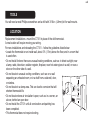
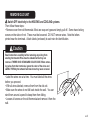
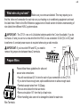
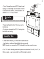
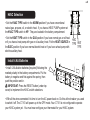
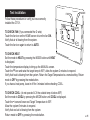
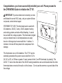
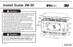
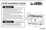
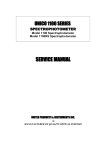
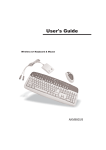
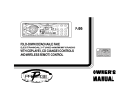
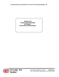
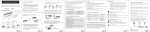
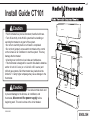
PG
1
Install Guide CT101
Caution
• Your thermostat is a precise instrument, handle it with care.
• Turn off electricity to the HVAC system before installing or
servicing thermostat or any part of the system.
• Do not turn electricity back on until work is completed.
• Do not short (jumper) across electric terminals at the control
on the furnace or air conditioner to test the system. This may
damage the thermostat.
• All wiring must conform to local codes and ordinances.
• This thermostat is designed for use with 4AA alkaline batteries
and/or 24 volt AC C wire (or a 12-24 AC or DC source) and
millivolt gas systems. Each thermostat relay load should be
limited to 1.0 amp; higher amperage may cause damage to the
thermostat.
Caution
To avoid electrical shock and
to prevent damage to the furnace, air conditioner, and
thermostat, disconnect the power supply before
beginning work. This can be done at the circuit breaker.
1202-003-002
top cover
Reset
button
Wire
terminals
Power Grid
status
indicator
Mode
button
MENU
button
HVAC
selections
switches
Touch screen
bottom
cover
ENGLISH
PG
TOOLS
You will need a small Phillips screwdriver and a drill with 3/16-in. (4.8mm) bit for wall mounts.
LOCATION
Replacement installations - mount the CT101 in place of the old thermostat.
A new location will require moving your wiring.
For new installations and relocating the CT101 - follow the guidelines listed below:
• Locate the thermostat on an inside wall, about 5 ft. (1.5m) above the floor, and in a room that is used often.
• Do not install it where there are unusual heating conditions, such as: in direct sunlight; near
a lamp, radio, television, radiator register, fireplace; near hot water pipes in a wall; or near a
stove on the other side of a wall.
• Do not locate in unusual cooling conditions, such as: on a wall
Good
separating an unheated room; or in a draft from a stairwell, door,
or window.
• Do not locate in a damp area. This can lead to corrosion that will
shorten thermostat life.
• Do not locate where air circulation is poor, such as: in a corner, an
5ft.
(1.5m)
alcove; behind an open door.
• Do not install the CT101 until all construction and painting has
been completed.
• This thermostat does not require leveling.
2
REMOVE OLD UNIT
Switch OFF electricity to the HEATING and COOLING systems.
Then follow these steps:
• Remove cover from old thermostat. Most are snap-on types and simply pull off. Some have locking
screws on the side or front. These must be loosened. DO NOT remove wires. Note the letters
printed near the terminals. Attach labels (enclosed) to each wire for identification.
Caution
• Label the wires one at a time. You must label all the wires
before you proceed.
• With all wires labeled, remove them from the old unit.
• Make sure the wires do not fall back inside the wall. You can
wind them around a pencil to keep them from falling.
• Loosen all screws on the old thermostat and remove it from the
wall.
W
Read instructions carefully before removing any wiring from
existing thermostat. Wires must be labeled before they are
removed. THERE IS NO STANDARD COLOR CODE. When removing wires from their terminals, ignore the color of the wires and
LABEL THEM by the lettered terminal where they were screwed.
C
G
PG
3
PG
4
What wires do you have?
Make sure your wires are labeled. This may require you to
find the ‘other end’ connection for each wire on your heating or air conditioning equipment and read
the label there. Refer to the Wire Reference page at end of install section for better understanding of
wire labels from different HVAC system makers.
IMPORTANT: The CT101 runs on 4 AA alkaline batteries and/or the C wire if available. If you do
not have a C wire you can run a new wire from the HVAC or use a standard 12-24V [AC or DC] wall
transformer. A constant power source is required when using a radio module.
IMPORTANT: If you have both RH and RC you need to
remove the jumper wire between these 2 terminals.
Prepare Wires
from HVAC
System
Jumper
wire
Y2
Y
2.6"
RH RC G A
C
RH
Y
W
Please follow these guidelines for safe and
secure wire connections:
• You will need at least 2.6” of wire for each of your connections to the CT101.
• If you do not have enough wire, splice additional wire to allow enough slack.
• Terminals accept wires from 16-22awg.
• Fan out wires below the hole as shown.
• Remove insulation 1/8” from the tip of each wire.
• When handling, take care not to damage the labels for each wire.
Wire Terminals
G
Find the step-by-step diagram for your system
W
CWRG
From
HVAC
R
W
C
Go To Page 13
Yn
R
C
G
G
W
C
B
R
4 Wire Heat Pump
w/o Aux Heat
O
From
HVAC
C
G
W
Go To Page 14
Y
R
or
Go To Page 15
Y
C B or O Y R G
From
HVAC
C W Y RH RC G
4 Wire
Heat/Cool
Go To Page 15
G
WIRES
Wn
Multi-stage Cool
Multi-Stage Heat
WIRES
WIRES
C
R
From
HVAC
Go To Page 13
C Wn Yn R G
From
HVAC
3 Wire
Heat
CWYRG
WIRES
WIRES
C
2 Wire
Heat
WIRES
WIRES
C W R
From
HVAC
5 Wire
Heat/Cool
Y
RH
RC
G
Go To Page 14
C B or O AUXn Yn R G
Multi-stage
Heat Pump w/
Multi-stage
Aux Heat
From
HVAC
C
B
O
Wn Yn R
or
G
• Select the referenece page
with your wiring diagram and
set-up information below.
• The C-wire is optional but
prefered for all installations
[shown dotted in diagrams].
• Hot Water systems
accessoroes are on Page 16
• If your combination of
wires is not above you can
use the wiring table at the
end if the install section to
determine your connections,
contact customer support for
help.
Go To Page 16
PG
5
PG
from HEAT/COOL system
• “Fan out” wires as illustrated with CT101 below the wall
opening. As in the example: fan out the wires so that the
C wire is above the C terminal, the W above the W. This
allows the CT101 to fit snug to the wall.
Caution
C
W
Y
RH
G
C B O W W2 Y Y2 RHRCG A
Do not allow wires to touch each other or parts on thermostat.
• Position the Wires behind the CT101 and up over the
terminal area.
• Do not bunch wires behind the CT101. Feed any slack
back into the wall opening.
Connect Your Wires
• Connect labeled wires only to a terminal with the same letter label.
• Insert the wire in the terminal well and tighten the screw securely.
NOTE: If you wish you can mount the CT101 to the wall first, and then connect the wires.
• The CT101 can be externally powered with a power source rated from 12V to 24V, AC or DC, at
300ma or greater. If used, connect to the C and RH terminals (no polarity).
6
Wall
Mount the CT101 to Wall
1. Hold the CT101 against the wall, with the wires coming over the top;
above terminal block. The CT101 will cover the hole in the wall.
2. Position CT101 for best appearance.
CT101
3. Attach the CT101 to the wall with the screws provided.
4. If you are mounting the CT101 to sheet rock or if you are using the old
mounting holes, use the plastic anchors provided.
5. Mark first and drill a 3/16-in.(4.8mm) hole for the insert at each screw
location, then mount the unit.
from
HEAT/COOL
system
C
W RH G
Y
Wires
Place wires like this
Wall
anchor
Screw to wall
PG
7
PG
HVAC Selection
HEAT�
PUMP
NORMAL
• Set the HVAC TYPE switch in the NORM position if you have conventional
natural gas, propane, oil, or electric heat. If you have a HEAT PUMP system set
the HVAC TYPE switch to HP. They are located in the battery compatrment.
• Set the HEAT TYPE switch in the GAS position if you have normal gas or oil heat
or if you have a heat pump with gas or oil auxiliary heat. Put the HEAT SOURCE in
the ELEC position if you have normal electric heat or if you have a heat pump with
electric auxiliary heat.
ELEC
GAS
HEAT�
TYPE
HVAC
TYPE
HVAC
TYPE HEAT
TYPE
Install 4 AA Batteries
• Install 4 AA alkaline batteries [required] following the
marked polarity in the battery compartments. Put the
battery in negative end first against the spring, then
push the positive end in.
IMPORTANT: Press the RESET button (under top
cover) to implement the HVAC switch selections.
AA
AA
AA
AA
• With all the wires connected it is time to turn the AC power back on. Do this at the breaker you used
to switch it off. The CT101 will power-up in the OFF mode. Your CT101 is not configured to operate
your HVAC system yet. You must now configure your thermostat for your HVAC system.
8
Caution
Special Thermostat Battery Cautions
Always replace the batteries as soon as the “Low Batt” flashes. The thermostat is a battery powered
device. You must be responsible to replace batteries before they run out. Failure to replace batteries can
result in overheating or excessive cooling of your house.
• Even if the “Low Batt” indicator does not flash, you should always replace the batteries at least once a
year. Replacing the batteries also helps to prevent leakage that can corrode and damage the thermostat.
• If you are leaving your home for a month or more, you should replace the batteries as a precaution
against battery failure in your absence.
• Always use new alkaline batteries.
BATTERY WARNING
Do Not Mix Old And New Batteries.
Do Not Mix Alkaline, Standard (Carbon - Zinc),
Or Rechargeable (Nickel - Cadmium) Batteries
DO NOT DISPOSE OF BATTERIES IN FIRE. BATTERIES
MAY EXPLODE OR LEAK.
• Failing to replace the batteries, when necessary,
could cause the thermostat to lose power or
malfunction. If the thermostat loses power, then the thermostat will not control the temperature which
could result in your HVAC system not functioning as you intended and lead to possible damage from
overheating or excessive cooling.
• If the thermostat batteries fail with the heat OFF, this can result in NO HEAT and possible frozen or
broken pipes and water damage.
• If the thermostat batteries fail with the cool OFF, this can result in NO COOL and could cause possible
damage or excessive temperatures.
PG
9
PG
HVAC Setup on Screen
IMPORTANT: Make sure the CT101 is powered up and
the mode is set to OFF. HVAC selection switches must be
set first [pg 8].
• With mode in OFF press MENU and touch HVAC SET UP.
• Use +/- icons to select HVAC SET UP number on screen.
The LCD display will show your selection and indicate the
number of stages you have selected. During setup, 2nd
stage will blink when both heat and cool have 2nd stages.
If you have a Normal HVAC system and
you want fast temperature recovery...
HEAT and COOL
select 1
2 stage HEAT, 1 stage COOL select 2
1 stage HEAT, 2 stage COOL select 3
2 stage HEAT, 2 stage COOL select 4
Caution
HVAC
SETUP
HEAT
2ND
STG
COOL
If you have a HEAT PUMP HVAC system...
HEAT PUMP with no AUX heat
select A
2stage HEAT PUMP with no AUX
select b
HEAT PUMP with AUX heat
select C
HEAT PUMP with 2stage AUX heat
select d
2stg HEAT PUMP with AUX heat
select E
2stg HEAT PUMP with 2stg AUX heat select F
Do not change he HVAC setup or HVAC selection switches if the
thermostat is included to Z-Wave network. The HVAC system must be changed, first EXCLUDE the
thermostat from the network, change the HVAC setup, and INCLUDE the thermostat to the network.
10
Test Installation
MODE
FAN
Follow these procedures to verify you have correctly
installed the CT101.
AUTO
TO CHECK FAN (If you connected the G wire):
Touch the fan icon on the HOME screen to turn the fan ON.
Verify that air is blowing from the system.
Touch the fan icon again to return to AUTO.
RADIO
1
MODE
F
LINK
TARGET TEMP
HEAT
MENU
TO CHECK HEAT
Set the mode to HEAT by pressing the MODE button until HEAT
is displayed.
Touch the temperature display to bring up the MANUAL screen.
Touch the + icon and raise the target temp to 90oF; allow the system 2 minutes to respond.
Verify that heat is blowing from the system. Return the Target Temperature to a nomal setting. Return
mode to OFF by pressing the mode button.
If you have a heat pump, leave in off for 4 minutes before checking COOL.
TO CHECK COOL (do not operate AC if the outside temp is below 65oF)
Set the mode to COOL by pressing the MODE button until COOL is displayed.
Touch the - icon and lower cool Target Temperature to 50oF.
Allow the system 5 minutes to respond.
Verify that cool air is blowing from the system.
Return mode to OFF by pressing the mode button.
PG
11
PG
Congratulations, you have successfully installed your unit. Please proceed to
the OPERATING Guide to initialize the CT101.
IMPORTANT: If you have labeled and connected your wires
and followed the correct HVAC setup, and your system still does
not operate, contact technical support.
STATEMENT OF USE: This thermostat can be used with
4AA batteries, 24VAC (C wire), 24VAC adapter, heating
and cooling systems and also millivolt heating. It cannot
be used with line voltage systems. This thermostat is digital
and your desired heat or cool temperatures can easily
be set on the large touch screen with the +/- buttons. A
minimum 4 minute off time protects the compressor from
damage. AUTO
RADIO
1
MODE
F
LINK
TARGET TEMP
HEAT
MENU
This thermostat runs on 4AA batteries. The CT101 can be
externally powered with a power source rated from 12V to
24V, AC or DC, at 300ma or greater. If used, connect to the C and RH terminals (no polarity). The
24VAC “C” wire is the other side of the 24VAC heating transformer and can be found where the other
thermostat wires connect at the wall or at the furnace. Do not use the common or ground side of the
line voltage.
12
Step-by-step wiring diagrams
WIRES
3 Wire Heat GAS MILLIVOLT or 24VAC system
STEP 1 - Connect the R (or RH) wire to the RH terminal. This
connects the heat power.
STEP 2 - Connect the W wire to the W terminal.
This connects the heat.
STEP 3 - Connect the C wire to the C terminal.
Your heater is now connected to the CT101.
Please Go To Page 6
HVAC SYSTEM
POWER
C
W
R
C B O W W2 Y Y2 RH RC G A
THERMOSTAT
WIRES
4 Wire Heat
STEP 1 - Connect the R (or RH) wire to the RH terminal. This connects the heat power.
STEP 2 - Connect the W wire to the W terminal. This connects the heat.
STEP 3 - Connect the G wire to the G terminal on the thermostat. This
HVAC SYSTEM
connects the fan.
C
W R G
POWER
STEP 4 - Connect the C wire to the C terminal.
Your system is now connected to the CT101.
Please Go To Page 6
C B O W W2 Y Y2 RH RC G A
THERMOSTAT
PG
13
PG
WIRES
W Y RH G 5 Wire Heat/Cool
STEP 1 - Connect the W wire to the W terminal. This connects the heat.
STEP 2 - Connect the Y wire to the Y terminal. This connects the cooling compressor.
STEP 3 - Connect the RH or R wire to the RH terminal. This connects the power.
STEP 4 - Connect the G wire to the G terminal on the thermostat.
HVAC SYSTEM
This connects the fan.
C
W Y R G
POWER
STEP 5 - Connect the C wire to the C terminal.
Your HVAC system is now connected to the CT101.
Please Go To Page 6
C B O W W2 Y Y2 RH RC G A
WIRES
W Y RH RC G
THERMOSTAT TERMINALS
6 Wire HEAT/Cool
STEP 1 - Connect the W wire to the W terminal. This connects the heat.
STEP 2 - Connect the Y wire to the Y terminal. This connects to the cooling compressor.
STEP 3 - Disconnect the Rc and Rh terminals by placing the Rc-Rh switch in the UP position.
STEP 4 - Connect the RH wire to the RH and the RC wire to the RC terminals. This connects power.
STEP 5 - Connect the G wire to the G terminal. This connects the fan.
STEP 6 - Connect the C wire to the C terminal.
Your HVAC system is now connected to the CT101.
Please Go To Page 6
C Wn Yn RH G
Multi-stage Heat and Multi-stage Cool
The CT101 can handle up to 2 stages of HEAT and 2 stages of
HVAC SYSTEM
POWER
C W
Y RH RC G
C B O W W2 Y Y2 RH RC G A
THERMOSTAT TERMINALS
*RC and RH
disconnected
14
COOL.
STEP 1 - Connect the W, W2 wires to the W terminals.
This connects the stages of HEAT.
STEP 2 - Connect the Y and Y2 wires to the Y terminals.
This connects the stages of COOL.
STEP 3 - STEP 5 - Connect the RH or R wire to the RH terminal.
This connects the power.
STEP 4 - Connect the G wire to the G terminal.
This connects the fan.
STEP 5 - Connect the C wire to the C terminal.
Your HVAC system is now connected to the CT101.
Please Go To Page 6
HVAC SYSTEM
POWER
C W W2 Y Y2
R G
C B O W W2 Y Y2 RH RC G A
THERMOSTAT TERMINALS
4 Wire Heat Pump (heat/cool) without Auxiliary Heat
STEP 1 - Connect O wire to the O terminal or B wire to the B. This connects the change-over valve.
If you have both O and B - connect only the O wire to the O terminal and D
O NOT connect B to B
terminal (see wire reference under Trane for B wire terminal).
STEP 2 - Connect the Y wire to Y terminal. This connects the compressor.
STEP 3 - Connect the R wire to RH. This connects the power.
HVAC SYSTEM
STEP 4 - Connect the G wire to the G. This connects the fan.
C
B O Y R G
STEP 5 - Connect the C wire to the C terminal.
POWER
or
Your HVAC system is now connected to the CT101.
or
Please Go To Page 6
C O or B AUXn Yn RH G Multi-stage Heat Pump with Multi-stage
C B O W W2 Y Y2 RH RC G A
THERMOSTAT TERMINALS
PG
15
PG
Aux Heat
The CT101 can handle up to 2 stages of Pump compression and 2 stages of AUX heat.
STEP 1 - Connect O wire to the O terminal or B wire to the B. This connects the change-over valve.
If you have both O and B - connect only the O wire to the O terminal and D
O NOT connect B to B
terminal (see wire reference under Trane for B wire terminal).
STEP 2 - Connect the AUX 1, AUX 2, to the AUX 1 and 2 respectively.
HVAC SYSTEM
This connects the auxiliary heat.
C
B O AUX1 AUX2 Y Y2 R
STEP 3 - Connect the Y and Y2 wires to the Y terminals.
POWER
or
This connects the compressor.
STEP 4 - Connect the R wire to RH terminal. This connects the power.
or
STEP 5 - Connect the G wire to G terminal. This connects the fan.
STEP 6 - Connect the C wire to the C terminal.
C B O W W2 Y Y2 RH RC G A
THERMOSTAT TERMINALS
Your HVAC system is now connected to the CT101.
Please Go To Page 6
Accessory Wiring Zoned Hot Water Heat -
For Solenoid valve or Motor valve connect the wires based on
diagrams below to the correct terminal on the CT80. USE ONLY
IN HEAT MODE. The third wire on your valve may be called 6,
Y, or G (see page 18). As always the CT80 must be powered by
24vac
G
FOR
R 3WIRE ZONED
HOT WATER
CT101
W
RH
W
R
A
A
MOTOR VALVE
CT101
AR
H
W
R
W
A
SOLENOID VALVE
16
Wire Reference Table
Possible WiresWhat They Control
R or V or VR RH and RC Single power for HEAT and COOL
RH or 4 RH Power for HEAT (RH not connected to RC jumper clip removed)
RC RC Power for COOL (RH not connected to RC jumper clip removed)
W W Heat control
W2 W2 2nd stage HEAT or heat pump auxiliary heat
W3W3 3rd stage HEAT or 2nd stage of 2 stage auxiliary heat
Y Y COOL control or 1st stage compression for heat pump
Y2 Y2 2nd stage COOL control or 2nd stage compression for a heat pump
G or F G FAN control
C or X C 24VAC power (to power thermostat)
NOTE: TRANE uses B for this connection
HH External Humidifier
DHDH External De-Humidifier
EXEX external fresh air baffle
B B Heat pump changeover (cool to heat, powered in heat)
O O Heat pump changeover (heat to cool, powered in cool)
B and O
IMPORTANT: If there are both B and O wires (Trane pump
products) DO NOT CONNECT B to B terminal, connect B to C
terminal. If not a Trane product tape off B.
E n/a Emergency heat (do not connect, tape off)
L n/a System monitor (do not connect, tape off)
T n/a Outdoor sensor (do not connect, tape off) Wire Reference
PG
17
PG
Wire Reference cont.
Possible Wires
Lennox Heat Pump
V or VR or R M or Y Y or W or W2 F or G R or O X or X2 or C What They Control
RH Power for HEAT
Y COOL control
W2 2nd stage HEAT
G Fan control
O
C
Trane Products [American Standard]
BC 24VAC power (to power thermostat)
W or W1
W2 2nd stage HEAT
X2
Emergency heat (do not connect, tape off) 3 Wire
Solenoid Valves
Zoned Hot Water
R 2 wire
W Your Wires
Thermostat Terminal
Y or G (the 3rd wire) R RH
W W
3 Wire
Motor Driven Valves
R or 5 RH (power)
W or 4W (heat ON)
Y or G or 6 (the 3rd wire)
A (heat OFF)
RH (power)
A (heat ON)
W (heat OFF)
18
FCC Warning: Changes or modifications to this unit not expressly approved by the party responsible for compliance
could void the user’s authority to operate the equipment.
NOTE: This equipment has been tested and found to comply with the limits for a Class B digital device, pursuant to
Part 15 of the FCC Rules. These limits are designed to provide reasonable protection against harmful interference in
a residential installation. This equipment generates, uses and can radiate radio frequency energy and, if not installed
and used in accordance with the instructions, may cause harmful interference to radio communications.
However, there is no guarantee that interference will not occur in a particular installation. If this equipment does cause
harmful interference to radio or television reception, which can be determined by turning the equipment off and on, the
user is encouraged to try to correct the interference by one or more of the following measures:
- Reorient or relocate the receiving antenna.
- Increase the separation between the equipment and receiver.
- Connect the equipment into an outlet on a circuit different from that to which the receiver is connected.
- Consult the dealer or an experienced radio/TV technician for help.
BATTERY WARNING
Do Not Mix Old And New Batteries.
Do Not Mix Alkaline, Standard (Carbon - Zinc), Or Rechargeable (Nickel - Cadmium) Batteries
DO NOT DISPOSE OF BATTERIES IN FIRE. BATTERIES MAY EXPLODE OR LEAK.
PG
19