1
PG
from HEAT/COOL system
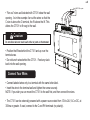
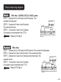
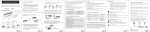
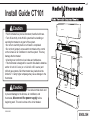
• “Fan out” wires as illustrated with CT101 below the wall
opening. As in the example: fan out the wires so that the
C wire is above the C terminal, the W above the W. This
allows the CT101 to fit snug to the wall.
Caution
C
W
Y
RH
G
C B O W W2 Y Y2 RHRCG A
Do not allow wires to touch each other or parts on thermostat.
• Position the Wires behind the CT101 and up over the
terminal area.
• Do not bunch wires behind the CT101. Feed any slack
back into the wall opening.
Connect Your Wires
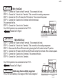
• Connect labeled wires only to a terminal with the same letter label.
• Insert the wire in the terminal well and tighten the screw securely.
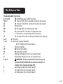
NOTE: If you wish you can mount the CT101 to the wall first, and then connect the wires.
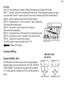
• The CT101 can be externally powered with a power source rated from 12V to 24V, AC or DC, at
300ma or greater. If used, connect to the C and RH terminals (no polarity).
6