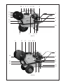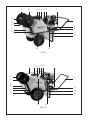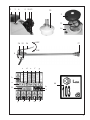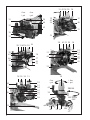
1
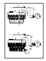
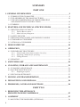
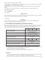
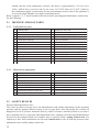
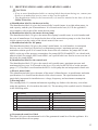
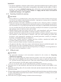
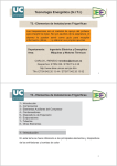
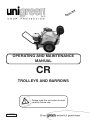
ISH
L
NG
E
OPERATING AND MAINTENANCE
MANUAL
CR
TROLLEYS AND BARROWS
Please read this instruction booklet
carefully before use.
01/2005
ALLOWED EQUIPMENTS
Pump
COMET PUMPS
ANNOVI REV.
PUMPS
COMBUSTION
MOTORS
ELECTIC
MOTOTRS
HOSE-REELS
SPRAYGUNS
WEED-KILLING
BOOMS
NOZZLES
NOZZLE TIPS
MC 20
WEIGHT IN Kg
2
CR 125P
X
MP 30
X
“ “
MP 40
X
“ “
APS 31
“ “
Pump
AR 252
“ “
CR 80
2R
CR 75
1R
CR 70
1R
CR 50P
X
X
X
X
X
X
X
X
X
X
X
AR 30
Oleo Mac
550
X
X
X
X
X
CM
46
X
X
X
X
X
B. & S.
6,5 HP
X
4 HP
X
X
X
X
X
X
X
X
X
X
X
X
X
X
X
Honda GX120
Tecumsen
X
5 HP
Honda GC160
5 HP
Honda GX160
5,5 HP
X
X
Robin
2 HP
X
B. & S.
3,5 HP
X
220 V
X
Monofase
Trifase
380 V
X
X
AVT.
20
X
X
X
X
“ “
40
X
X
X
X
“ “
50
X
X
X
Lever Spraygun
X
X
“Mitra” Spraygun
X
X
3 mt Weed-killing boom
X
X
Standard Nozzle
X
X
Antidrip Unijet Nozzle
X
X
Fan
KEMATAL
X
X
“
“
CERAMIC
X
X
“
“
BRASS
X
X
“
“
X
X
X
X
Stainless-Steel
Cone
LAWNMOWER
CR 125P
CERAMIC
Tow-hook kit
X
X
Net Weight (full optionals)
55
80
45
45
30
30
Total Weight (full optionals)
180
205
125
120
100
80
20 1 2 3
4 5 21
6
19
18
17
7
16
15
9
8
10
13
14
12 11
CR 75
1
17
13
2 3 21 5
7
18
4
6
14
16
15
11
10
8
4
CR 50
3
1
17
2 3 4 5 21
8
18
7
20
19
6
9
16
15
11
10
14
12
CR 80
1
2 3 4 5 21
6
18
17
7
16
8
15
9
11
10
14
13
12
CR 125
4
2
3
4
5 21 12
22
2
23
16
24 25
OFF
26
27
ON
S
c
d
e
f
g
b
a
44
h
i
11
p
o
n
m
l
5
31 43 38 29 30
+ bar
+ psi
- bar
- psi
32
33
39
33
28 42 31 29 30
28 31 43 36 29 30
32
42
34
40
38
37
32
34
36
37
38
41
33
40
41
33
39
39
28 29 30 31
41
40
40
42
38
42
35
32
42
34
29
40
31
29
32
33
34
35
36
37
38
- bar
- psi
+ bar
+ psi
42
PRESS
30
BY-PASS
OFF
39
40
6
36 41
ON
13
12
1
16
4
22
13
4
1
16
12
5
7
SUMMARY
PART ONE
1. GENERAL INFORMATION _______________________________________9
1.1 TERMS OF THE GUARANTEE..................................................................................9
1.2 THE ADDRESS OF THE MANUFACTURER..........................................................10
1.3 USE AND CONSERVATION OF THESE OPERATING
AND MAINTENANCE INSTRUCTIONS ................................................................10
1.4 SYMBOLS .................................................................................................................11
2. FEATURES AND TECHNICAL SPECIFICATIONS__________________11
2.1 IDENTIFICATION OF PARTS...................................................................................12
2.1.1 Trolley/Barrow parts ......................................................................................12
2.1.2 Motor-driven pump parts ...............................................................................12
2.2 SAFETY DEVICES ....................................................................................................12
2.3 IDENTIFICATION LABEL AND WARNING LABELS...........................................13
2.4 STANDARD ACCESSORIES ....................................................................................14
2.5 OPTIONAL ACCESSORIES ......................................................................................14
3. DESIGNATED USE _____________________________________________14
4. OPERATION ___________________________________________________15
4.1 PRELIMINARY PROCEDURES ...............................................................................15
4.1.1 Control and connection to mains electricity...................................................16
4.1.2 Preparing chemicals for spraying ..................................................................17
4.1.3 Filling the tank ...............................................................................................17
4.2 SPRAYING..................................................................................................................18
5. SWITCHING OFF ______________________________________________20
6. CLEANING, STORAGE AND MAINTENANCE _____________________21
6.1 CLEANING AND STORAGE ....................................................................................21
6.2 ROUTINE MAINTENANCE .....................................................................................22
6.2.1 Diaphragm rupture .......................................................................................22
6.3 SPECIAL MAINTENANCE.......................................................................................23
7. MOVING AND TRANSPORTATION_______________________________23
8. DISMANTLING AND DISPOSAL _________________________________24
9. PROBLEMS, CAUSES AND SOLUTIONS __________________________24
PART TWO
1. REMOVING THE APPLIANCE
FROM ITS PACKING MATERIALS _______________________________25
2. ASSEMBLY ____________________________________________________25
2.1 MOUNTING THE HOSE REEL (OPTIONAL)..........................................................26
8
INTRODUCTION
This manual is divided into two separate sections.
The first is for use by the end user and the Skilled Technician; the second is for use by the Skilled
Technician alone.
Skilled Technician means a person, generally employed by the service centre, who has received
appropriate training and is authorised to carry out special maintenance and repairs on the appliance
(the term “appliance” is used to indicate both trolleys and barrows). Any work on electrical parts
must be carried out by a Skilled Technician who is also a Qualified Electrician, i.e. a person
with professional training who is authorised to check, install and repair electrical equipment
correctly and according to the current regulations in the country where the appliance is installed.
CAUTION
• The appliances are supplied in a kit and must be assembled; the motor-driven pump
(operated by an electric motor or combustion engine) must be the type recommended by the
Manufacturer. Other types of motor-driven pumps must not be used unless prior authorisation
is granted by the Manufacturer.
• The kits must be assembled and the motor-driven pump must be installed by a Skilled
Technician according to the instructions contained in part two of these instructions.
The Declaration of Conformity contained at the end of this section in the instructions is
only guaranteed if the above requisites are met.
PART ONE
1. GENERAL INFORMATION
Congratulations for choosing one of our products! We would like to remind you that we took the
safety of the operator, the efficiency of its use and the protection of the environment into great
consideration when designing and manufacturing this product.
In order to preserve its features over time, please read and follow these instructions carefully.
Particular attention must be awarded to the parts with the following symbol:
CAUTION
as they contain important instructions regarding safety when using the appliance.
The Manufacturer is not liable for damage caused by:
•
failure to comply with these instructions and the instructions for the combustion engine, if
any, used with the appliance;
•
use of the appliance not included in the list in the “DESIGNATED USE” section;
•
failure to comply with current safety regulations and regulations for the prevention of
accidents in the workplace when using the appliance;
•
tampering with the safety devices and devices limiting the maximum operating pressure
•
incorrect installation
•
failure to carry out the required maintenance;
•
modifications or actions without prior authorisation by the Manufacturer;
•
use of non-original or non-specific spare parts or accessories for this model of appliance;
•
repairs which were not carried out by a Skilled Technician.
1.1
TERMS OF THE GUARANTEE
The guarantee is valid for a period of 24 months from the date on the sales document (receipt,
invoice etc.) provided the guarantee certificate included with the appliance’s documents was sent
9
back to the Manufacturer within 10 days of the purchase date with all its parts filled in.
The purchaser has sole right to the replacement of the parts that are deemed faulty by the
Manufacturer, or by his authorised representative, as regards their material or manufacture. This
does not imply any right to compensation for any type of direct or indirect damage. Any costs for
labour, packing and transportation are at the purchaser’s expense.
Should the product be sent to the Manufacturer for repairs under this guarantee, on arrival it must
be complete with all its original parts and not be tampered with. Any request under this guarantee
will be refused if this is not the case.
All replaced parts become the property of the Manufacturer.
Any faults or failures which occur during or after the period of the guarantee do not imply the
right to suspend payment or to any further extension.
This guarantee does not cover the replacement of the appliance and automatically becomes void
should the agreed terms of payment not be abided by.
The following are not covered by the guarantee:
•
direct or indirect damage, of any type, caused by falls, incorrect use of the appliance and
failure to observe regulations regarding safety, installation, operation and maintenance
which are contained in these instructions and the instructions for the combustion engine, if
any, used with the appliance;
•
damages due to the inactivity of the appliance for repairs;
•
any parts which are subject to wear during normal use;
•
any parts which are deemed faulty due to negligence or carelessness during use;
•
damage caused by the use of non-original spare parts or accessories or any not expressly
authorised by the Manufacturer, and by repairs not carried out by a Skilled Technician
•
damage caused by incorrect electrical power supply or the use of unsuitable fuel.
The guarantee becomes void should the appliance be tampered with, especially its safety and
maximum pressure limiting devices, and the Manufacturer will no longer be held liable.
The Manufacturer reserves the right to make any modification at any time which it deems
necessary to improve the product and is not liable to make these modifications to previously
manufactured products, be they delivered or under delivery.
The conditions in this section exclude any previous explicit or implicit condition.
1.2
THE ADDRESS OF THE MANUFACTURER
The address of the Manufacturer of this appliance is given in the Declaration of Conformity,
and at the end of this instruction manual.
1.3 USE AND CONSERVATION OF THESE OPERATING AND
MAINTENANCE INSTRUCTIONS
CAUTION
• These operating and maintenance instructions must be used in conjunction with those for
the combustion engine, if any, which is used with the appliance. The latter, which is taken
as copied in full in this booklet, must always be kept with the appliance and read carefully
in addition to these instructions.
The operating and maintenance instructions are an integral part of the appliance and they must
be kept in a safe place for future reference so that they may be readily consulted in case of need.
The operating and maintenance instructions contain important information for the safety of the
operator and of any people near him and for the protection of the environment.
In case of deterioration or loss, a new copy should be requested from the dealer or from an
authorised service centre.
If the appliance is passed on to a third party, please make sure these operating and maintenance
10
instructions are also given to the new owner.
We take great care when drawing up our instructions. If you note any mistakes, please do inform
the Manufacturer or an authorised service centre.
The Manufacturer reserves the right to modify, update and correct these instructions without
notice.
It is illegal to copy these instructions, even partially, without prior authorisation by the
Manufacturer in writing.
1.4
SYMBOLS
The symbol:
CAUTION
next to certain parts of the text, is to indicate that there is the firm possibility of injury to persons
if the relative instructions and indications are not followed.
The symbol:
WARNING
next to certain parts of the text, is to indicate that there is the possibility of damaging the
appliance if the relative instructions are not followed.
2. FEATURES AND TECHNICAL SPECIFICATIONS
Barrows (one wheel) and trolleys (two wheels) are made up of a supporting tubular steel frame,
a polyethylene tank, rubber hoses, a sprayer lance and a motor-driven pump with an electric
motor or combustion engine. They may also be fitted with a hose reel (optional).
CR 50
ELECTRICAL CONNECTION
FUEL
PUMP OIL
REDUCER OIL
CR 75
CR 125
AGIP SAE 20W/40
(AGIP Blasia S 150 only for MC16)
(only for MP30, MP40, APS31 and APS 41)
AGIP SAE 80W/90
HYDRAULIC SUPPLY
Maximum inlet water temperature
Minimum inlet water temperature
Tank capacity
EFFICIENCY
Maximum acoustic pressure level with electric motor
Maximum acoustic pressure level with combustion engine
Acoustic power level with electric motor
Acoustic power level with combustion engine
WEIGHT
CR 80
Voltage, frequency and power are given
on the electric motor’s label.
The fuel to be used is given in the instructions
for the combustion engine
40˚ C (104˚ F)
5˚ C (41˚ F)
55 l
14.5 US gal
75 l
19.8 US gal
80 l
21.1 US gal
125 l
33.0 US gal
Maximum pressure and flow rate are given
on the pump’s label.
84 dB (A)
88 dB (A)
101 dB(A) - guaranteed level is 103 dB(A)
106 dB(A) - guaranteed level is 108 dB(A)
Refer to data given on barrow/trolley’s label
• For appliances fitted with a combustion engine, the specifications given refer to atmospheric pressure
of 1013 hPa at sea level with a room temperature of 16°C / 61°F.
• Features and technical specifications are approximate.
• The Manufacturer reserves the right to modify the appliance without notice
WARNING
• In order to supply full power, the combustion engine must be run in for at least 10 hours
with a load that is 15-20% below the appliance’s maximum efficiency.
• With the combustion engine, the maximum power that can be supplied decreases as the
11
altitude and the room temperature increase (the drop is approximately 3.5% for every
305m / 1000 ft above sea level and 1% for every 5.6°C/42°F above 16°C/61°F). Refer to
the combustion engine’s instructions for any precautionary steps to take if the appliance is
to be used at high altitudes or at high room temperatures.
Refer to figures 1, 2, 3 and 4 located at the start of these operating and maintenance instructions
for the following.
2.1
2.1.1
2.1.2
2.2
IDENTIFICATION OF PARTS
Trolley/Barrow parts
1
Delivery hose
15
Support for hose reel
2
Cover
16
Tank
3
Aperture for passage of by-pass hose
17
Central hose reel coupling
4
By-pass hose
18
Hose reel (optional)
5
Intake filter (external)
19
Hose reel handle
6
Identification label for barrow/trolley
20
Side hose reel coupling
7
Handle
21
Filter coupling
8
Connection hose
22
Intake filter (internal)
9
Base
23
Filling filter
10
Tank discharge cap
24
Spray angle adjustment/blocking
11
Warning label
25
Lance coupling
12
Intake hose
26
Lance lever
13
Lance
27
Nozzle
14
Frame
Motor-driven pump parts
28
Filling cap for reducer oil
37
Pressure gauge
29
Pressure adjustment knob
38
Identification label for pump
30
By-pass/pressure lever
39
Identification label for motor-driven pump
31
Filling cap for pump oil
40
Coupling for delivery outlet
32
Volumetric oil compensator
41
Tap lever
33
Intake coupling
42
By-pass coupling
34
Hook
43
Pressure accumulator
35
Identification label for control unit
44
Label with guaranteed sound level
36
Inlet tap
SAFETY DEVICES
Pressure limit/adjustment valve
This valve has been correctly set by the Manufacturer and enables adjustment of the operating
pressure and the pumped fluid to return to the by-pass hose, thus preventing the creation of
dangerous levels of pressure when the delivery outlet is closed or should pressure be set that is
above permitted levels. A pressure limit/adjustment valve complete with interception/distribution
devices for the pumped liquid (for example taps) is usually called a pump control unit. For
simplicity’s sake, these instructions use the term control unit to refer to both the pressure limit/
adjustment valve and the pump control unit.
12
2.3
IDENTIFICATION LABEL AND WARNING LABELS
CAUTION
• If one or more identification labels or warning labels deteriorate during use, contact your
dealer or an authorised service centre so they can be replaced.
• The identification label for the barrow/trolley (6) must be attached to the base (9) by the
Skilled Technician
a) Identification label for the barrow/trolley
The identification label (6) gives the barrow/trolley’s model name, its weight when empty, its
tank capacity, and the year of manufacture. It is located on the base (9). For the appliance’s
serial number, refer to that of the motor-driven pump.
b) Identification label for the motor-driven pump
The identification label (39) gives the motor-driven pump’s model name, its serial number and
the year of manufacture. It is located on the base of the motor-driven pump or on the foot of the
electric motor or on the casing of the electric motor’s fan cover.
c) Identification label for the pump
The identification label (38) gives the pump’s model name, its serial number, its maximum
delivery rate (at 0 bar/0 psi) its delivery at maximum pressure, maximum pressure and
maximum rotation speed. It is located on the front of the oil crankcase for pumps MC16 and
MP30; on the top of the pressure accumulator for pumps MC20/20 and MC25; on a head (with
adhesive label) for pumps APS31 and APS41; on a special label case fixed to a screw on one of
the heads for pumps MP40.
d) Identification label for the control unit
The identification label (35) gives the control unit’s model name, maximum pressure and
maximum delivery rate. It is located on the lever (30) (only for MC20/20) or on the pressure
gauge (37). This label is not found on the MC16 as this pump has an incorporated control unit.
e) Electric motor label
This identification label gives the name of the motor’s Manufacturer, its model name and main
specifications. It is located on the chassis of the electric motor. The specifications that are
particularly important for installation are: voltage, frequency, and maximum consumption.
f) Warning label
The warning label (11) contains information regarding any further risks that may exist when
using the appliance. It is located on the tank (16). The meaning of the symbols used is illustrated
in the following table:
a
b
c
d
e
f
g
No smoking
Read instruction manual
Do not remain in range of the appliance
Do not abandon waste in the environment
Do not remove safety devices
Do not lubricate or clean when in use
Do not drink! Water not safe for drinking
h
i
l
m
n
o
p
Poisonous
Corrosive
Wash hands after each use
Wear gloves
Wear mask
Wear ear protection
Wear protective clothing
g) Guaranteed sound level label
This label (44) gives the maximum level of the guaranteed sound level for the appliance. It is
located on the motor-driven pump.
13
2.4
STANDARD ACCESSORIES
Check that the product purchased is made up of the following parts:
•
barrow/trolley with the chosen motor-driven pump;
•
hose reel (if this optional has been chosen);
•
lever lance with standard nozzle (1.5mm Ø);
•
operating and maintenance instructions for combustion engine, if any.
•
operating and maintenance instructions for barrow/trolley;
•
guarantee certificate.
Please contact your dealer or authorised service centre if there are any problems with the above.
2.5
OPTIONAL ACCESSORIES
CAUTION
• The operation of the appliance may be impaired if unsuitable optional accessories are used
and may even make it dangerous. Only use the original optional accessories endorsed by
the Manufacturer.
• Refer to the documents provided with the optional accessories for information regarding
their general use, safety warnings, installation and maintenance.
The standard accessories for the appliance can be integrated with the following range of
accessories:
• hosereel(variousmodelsaccordingtothetypeofappliance);
• weedkillingbars(onlyforCR125)
• “Multispray”spraylance;
• spraylancewithknob;
• highpressurelance;
• varioustypesofnozzleholderheads;
• varioussizesofnozzles.
Please contact your dealer for further details.
3. DESIGNATED USE
CAUTION
• This appliance is to be used exclusively for:
- spraying and protection of plants in gardens, greenhouses, lawns and small cultivated areas;
- distributing detergents and soluble paints that have been diluted in water;
- spraying water not for human consumption.
• This appliance is not to be used for spraying:
- water based solutions whose density and viscosity is greater than that of water;
- chemical solutions if their compatibility with the materials that the appliance is made of,
is not known;
- seawater or water with a high salt content;
- all fuels and lubricants;
- inflammable liquids or liquid gas;
- liquids meant for human consumption;
- all solvents and diluents;
- all non-soluble paints and varnishes;
- liquids at a temperature above 40°C or below 5°C;
- liquids containing granules or suspended solid matter.
14
• The appliance must not be used to wash people, animals, energized electrical appliances,
delicate objects or the appliance itself.
• The accessories (standard and optional) used with the appliance must be those endorsed by
the Manufacturer.
• The appliance is not suitable for use:
- in situations where certain conditions may be found such as in corrosive or explosive
atmospheres;
- in a closed space if it is fitted with a combustion engine.
• Contact the Manufacturer’s service centre before use on board vehicles, ships or airplanes,
as there may be additional instructions for use.
Any other use is considered improper.
The Manufacturer is not liable for any damage caused by improper or incorrect use.
4. OPERATION
4.1
PRELIMINARY PROCEDURES
CAUTION
a)
b)
c)
d)
• Check that all the delivery outlets are closed or connected to closed applications (for
example closed tap (36) or spray lance in its closed position).
• Check that all the hooks (34) located on the control unit have been inserted correctly.
Particular attention must be paid to any control units that are secured to the pump by means
of a hook.
• Check the grips that connect the hoses to their respective couplings are fastened down
tightly.
• Make sure the appliance’s moving parts are suitably protected and are not accessible to
unauthorised personnel.
• Do not use the appliance if:
- the power supply cable or other important parts, such as the high pressure delivery hose
(1), the safety devices or the lance, are damaged;
- it has been tipped over or has been bumped;
- there are obvious leaks of oil.
- there are obvious leaks of liquid.
In these circumstances, the appliance should be tested by a Skilled Technician.
• Under no circumstances should the inflation pressure of the pressure accumulator (43)
(when present) exceed the maximum values shown in the table below.
• Make sure the special maintenance checks are carried out by a Skilled Technician.
Checkthattheconditionsoftheplantsorcropsactuallyrequiretreatment.
Followthepreliminaryproceduresindicatedintheoperatingandmaintenanceinstructionsfor
combustionenginefittedwiththeappliance,ifany.Inparticular,remembertorefuelandto
checkthelevelofoilintheengine.
Whentheengineisoffandtheappliancehascooleddowncompletely,checkthelevelofthe
pumpoilcorrespondstothereferencenotchfoundonthevolumetriccompensator(32).
Ifitmustbetoppedup,refertothetypesoflubricantsshowninthesectionon“FEATURES
AND TECHNICAL SPECIFICATIONS”.
Checkthattheinflationofthepressureaccumulator,ifany,iscorrectusinganormalcompressed
airgunwithpressuregauge,suchasthoseusedtocheckthepressureofcartyres.
Theinflationdependsonthefieldofpressurewheretheapplianceistobeused,asshownin
thetablebelow:
15
PUMP OPERATING PRESSURE
PRESSURE ACCUMULATOR INFLATION
bar
psi
bar
2-5
29-73
2
psi
29
5-10
73-145
2-5
29-73
10-20
145-290
5-7
73-102
20-40
290-580
7
102
e) Checktheexternalintakefilter(5)isclean(onlyforCR75,CR80andCR125).
WARNING
• Make sure ice has not formed inside the pump, hoses and tank if the appliance is used in
very low temperatures.
• The routine maintenance checks must be carried out, particularly those concerning the
oil.
4.1.1
Control and connection to mains electricity
CAUTION
• A Skilled Technician must check that the electrical supply complies with the data indicated
on the electric motor’s identification label. It is especially important that the supply voltage
does not differ more than +-5% from that indicated on the label.
• The connection to mains electricity must be carried out by a Qualified Electrician according
to IEC 364 regulations or the equivalent standard in the country where the appliance is to
be used. It is especially important that the current outlet where the appliance is connected
is provided with an earth conductor, a suitable fuse, and it must be protected by a magnetothermal differential circuit breaker, whose sensitivity is not in excess of 30 mA. It must be
possible to insulate the appliance from the mains electricity with a universal switch with 3
mm minimum opening between its contacts.
• If the appliance is not to be connected permanently to the electric supply and the power
cable is not provided with a plug, contact a Qualified Electrician for the installation of a
plug according to the current regulations in the country where the appliance is to be used.
• If the appliance is to be connected permanently to the electric supply, it must be installed
by a Qualified Electrician according to IEC 364 regulations or the equivalent standard in
the country where the appliance is to be used. It is especially important that regulations
are followed concerning its connection to earth, protection by a suitable fuse and magnetothermal differential circuit breaker, whose sensitivity is not in excess of 30 mA, and the
insulation of the appliance from the mains electricity with a universal switch with 3 mm
minimum opening between its contacts.
Note: to facilitate the reader, these operating and maintenance instructions always assume
that the appliance is connected to the electrical supply with a plug.
If the appliance is connected permanently to the electrical supply, it is presumed that:
- when the universal circuit breaker is in the off position (‘0’ position) it is equivalent to the
plug being disconnected from the current outlet.
- when the universal circuit breaker is in the on position (‘1’ position) it is equivalent to the
plug being inserted in the current outlet.
• If the power supply cable is too short, an extension cord can be used provided it is no longer
than 50 m /164 ft, the section of the wires is at least 1.5mm² and the plug and the socket are
waterproof. Contact a Qualified Electrician to ensure all these requirements are met.
• The use of unsuitable extension cords can be dangerous.
• Do not use adaptors between the electric plug and the current outlet.
16
WARNING
• For electric appliances with three-phase motors, particular attention must be paid to ensure
the direction of rotation of the motor corresponds to that shown on the reducer. If this is
not the case, contact a Skilled Technician who will be able to solve the problem by simply
inverting a wire inside the power plug. Failure to comply with the above will result in
considerable damage to the appliance.
4.1.2
Preparing chemicals for spraying
CAUTION
• Keep products in a ventilated place with a door that can be locked. Products must be kept
out of reach of children and unauthorised adults. Appropriate warning notices should be
placed outside to inform of the danger.
• Read instructions and safety information provided on the chemical product’s container
carefully so that the most appropriate action may be taken to avoid endangering oneself or
the environment. It is especially important that the maximum recommended concentrations
are not exceeded, that only the amount of product needed for the treatment is prepared and
that spillages onto soil and into water are avoided.
• Should chemicals come into contact with your eyes, wash immediately with water. Contact
a doctor without delay and remember to take the product’s container with you.
• Should chemicals be swallowed, do not provoke vomiting. Contact a doctor without delay
and remember to take the product’s container with you. Avoid inhaling the fumes that
develop by using appropriate equipment for personal protection (a mask, for example).
Drinking, eating and smoking are prohibited.
• Always wear suitable protective clothing and keep children, unauthorised adults and
personnel without protection at a safe distance.
• Always wash your hands and face carefully after finishing work.
• All garments that have come into contact with chemicals must be washed thoroughly. Any
item that may have been contaminated must be cleaned immediately.
• The containers used for chemicals must be disposed of according to current legislations in
the country where the appliance is used.
4.1.3
Filling the tank
CAUTION
a)
b)
c)
d)
• Pay particular attention to the instructions contained in the section on “Preparing
chemicals for spraying”.
• Take care to avoid spilling the product onto the ground or into water when filling the tank.
• Water must only be added to the tank using free-fall water pipes or indirectly (jugs, drums,
etc). The hose used for filling must never come into contact with the liquid contained in the
tank. Do not connect up to the mains supply of drinking water.
• Do not over fill the tank; only fill with the amount of product needed for spraying.
Turn the cover (2) anti-clockwise and check that the aperture located in the middle is not
blocked.
Checkthatthefillingfilter(23),theinsideofthetankandtheinternalintakefilter(22)(only
CR50)areclean.
Fillupwiththeproducttobesprayed.Werecommendatrialrunwithcleanwaterbeforestarting
tospraywithproductforthefirsttimeinordertochecktheapplianceisworkingcorrectlyand
togetusedtooperatingit.
Closethecover(2)again,turningitclockwisebutnotforcingit.
17
4.2
SPRAYING
CAUTION
• Pay particular attention to the instructions contained in the section on “Preparing
chemicals for spraying”.
• While you are spraying, avoid spraying the product on buildings, houses, public or
private land, gardens, roads, public or private courses of water and areas used by people
or animals. Spraying in close proximity of these areas must be carried out when it is not
windy.
• Before starting up the appliance, read these instructions carefully as well as those for the
combustion engine, if any, which is used with the appliance. It is particularly important that
you have understood how the appliance works regarding the intercepting of liquids.
• The appliance must be used with due care and attention. It is your responsibility to make
sure that any infrequent users have read these instructions and those for the combustion
engine, if any, which is used with the appliance, and are acquainted with the operation of
the appliance. This appliance must not be used by children or by unauthorised personnel
• Comply with the safety warnings in the operating and maintenance instructions of the
combustion engine, if any, used with the appliance.
• Comply with the safety warnings in the operating and maintenance instructions of any
optional accessories to be used
• It is especially important to pay great attention when the appliance is used in areas where
there are moving vehicles as these can crush or damage the power supply cable, the
delivery hose, the spray gun etc.
• During operation, never leave the appliance unattended and make sure it is out of reach
of children and animals. Pay particular attention when using it in kindergartens, nursing
homes and old people’s homes, as unsupervised children, elderly people and disabled
people may be present in such places.
• Before using the appliance, make sure it is in a dry place and that it is in a flat and stable
position in order to avoid accidents and prevent it from falling over.
• Before moving the appliance, follow the instructions in the “Switching off” section.
• Use personal protective clothing, which guarantees adequate protection against noise (for
example headphones).
• Before operating the appliance, put on clothing which guarantees adequate protection
against the possibility of incorrect manoeuvres of the jet of pressurised liquid and the
chemicals used. Do not operate the appliance near people, unless they are also wearing
protective clothing, or animals.
• High-pressure jets of water can be dangerous if they are not used properly. Do not point the
jet in the direction of people, animals, and energized electrical appliances or towards the
appliance itself.
• Do not point the jet towards oneself or other people in order to clean off clothing or
footwear.
• Do not point the high-pressure jet towards materials containing asbestos or other harmful
substances
• Hold the spray gun firmly during use because the operator is subjected to the backlash of
the high-pressure jet when the control lever is operated to spray the product.
• Do not use the appliance in the rain.
• Pay particular attention to the instructions in the “Controls and connection to mains
electricity” section.
18
a)
b)
c)
d)
e)
f)
• Follow the instructions in the “Switching off” section:
- when the appliance is not is use;
- before leaving the appliance unattended, even for a short time;
- before topping up the chemicals;
- after use;
• Do not remove the plug from the power outlet by pulling on the power supply cable.
• Keep the power supply cable, any extension cords, the plugs and the outlets dry. Do not
touch them with wet hands.
• Should the power supply cable be damaged, contact a Qualified Electrician for its
replacement.
• Do not cover the appliance during operation and do not put it where there is inadequate
ventilation.
• When the appliance is used in enclosed spaces, make sure that there is adequate ventilation.
The appliance must not be used in enclosed spaces if it is operated with a combustion
engine.
• Do not get close to moving parts on the appliance, even if there are suitable devices for
protection.
• Do not remove the protective devices from moving parts.
• Do not tamper with hoses containing pressurised liquids.
• Do not carry out maintenance on the appliance when it is operating.
• Follow the instructions in the “DESIGNATED USE” section;
• Do not alter the appliance’s installation conditions: it is especially important not to alter its
assembly and hydraulic connections.
• Do not operate any taps mounted on the appliance unless they are connected to a utility that
prevents the pumped liquid being released by accident.
• Do not neutralise or tamper with the safety controls and devices and the pressure limit/
adjustment valve.
• Operating pressure must never exceed the maximum amount specified for the appliance
(also refer to the “FEATURES AND TECHNICAL SPECIFICATIONS” section).
Unroll the delivery hose (1) completely.
Check that the adjuster (24) for the lance (13) is turned completely towards “S” so that
the lever (26) can be put in the “OFF” position. Put the tap lever (41), if any, in the “OFF”
position.
Check that there is no pressure in the delivery hose as follows:
turn the knob (29) on the adjustment valve anti-clockwise as far as it will go; this is only
necessary for MC16 as it does not have lever (30).
operate lever (30) and put it into the “BY-PASS” position.
Start up the appliance so it can prime. If the appliance is fitted with an electric motor, operate
both the universal circuit breaker on the socket that the appliance is connected to, and the
switch on the electric motor, if any, by putting them both in position “1” (please remember
to take into account the recommendations regarding three-phase motors in the “Controls
and connection to mains electricity” section). For appliances fitted with a combustion
engine, follow the instructions for the start up of the same in its operating and maintenance
instructions.
Bring the appliance up to pressure as follows:
operate lever (30) putting it in position “PRESS”.
turn the knob (29) until the required pressure is reached (turn clockwise to increase
pressure, anticlockwise to decrease). The level of pressure is shown on the pressure
gauge (37) (if any).
Put the tap lever (41), if any, in the “ON” position
19
g)
Operate the lever (26) on the lance (13) to achieve the required spraying angle (from an
empty cone to a needle-point jet). The adjuster (24) can be used to fix the preferred position
for spraying. We recommend this is done while spraying with the lance into the tank to avoid
wasting chemicals.
The flow rate of the sprayed liquid depends on the operating pressure, the nozzle (27) used
(the 1.5 mm Ø nozzle is supplied as standard with the appliance) and the adjustment of the
spray angle. Refer to the table below for information on which nozzle to use for a job (note
that the maximum flow is indicated, i.e. corresponding to a needle-point spray angle).
h)
Pressure (bar)
Nozzle Ø
5
10
15
20
30
40
1.0
1.0
1.5
1.8
2.1
2.5
2.9
1.2
1.5
1.4
2.0
1.9
2.8
2.4
3.4
2.8
3.9
3.4
4.8
3.9
5.6
1.8
2.2
3.2
3.9
4.5
5.5
6.3
2.0
2.6
3.7
4.5
5.2
6.4
7.4
(mm)
Flow rate (l/min)
WARNING
• Follow step c) each time the tank is emptied of liquid to ensure the appliance will prime
quickly.
• We recommend checking the pump oil level after the first few hours of operation and to top
it up if necessary as indicated in the “PRELIMINARY PROCEDURES” section.
5. SWITCHING OFF
CAUTION
• Always check that there are no moving parts on the appliance and there is no pressurised
liquid in the hoses after the following instructions for switching off have been
completed.
• When switching off the appliance and leaving it to cool down, take care that:
- the appliance is not left unattended in the presence of unsupervised children, elderly or
disabled people.
- the appliance is in a stable position and not at risk of falling over.
- the appliance is not in contact with inflammable materials, or in their immediate
vicinity.
a) Eliminatethedeliverypressureasinstructedinpointc)inthe“Spraying”section.
b) Iftheapplianceisfittedwithanelectricmotor,operateboththeswitchontheelectricmotor,if
any,andtheuniversalcircuitbreakeronthesocketthattheapplianceisconnectedto,byputting
thembothinposition“0”andremovetheplugfromthepoweroutlet.Forappliancesfitted
withacombustionengine,followtheinstructionsforswitchingoffthesameintheengine’s
operatingandmaintenanceinstructionsandthendisconnectthesparkplug.
c) Putthelancelever(26)inposition“ON”sothatanyresidualpressureisdischarged.
6. CLEANING, STORAGE AND MAINTENANCE
CAUTION
20
• Pay particular attention to the instructions contained in the section on “Preparing
chemicals for spraying”.
• Only start cleaning and maintenance once the instructions in the ‘Switching off’ section
have been completed, i.e. when there are no moving parts on the appliance, there is no
pressurised liquid in the hoses and the appliance has cooled down completely.
It is particularly important to always disconnect the electricity supply (or disconnect the
spark plug if the appliance is fitted with a combustion engine).
• Cleaning and maintenance must only be carried out if the appliance is on a flat surface and
in a stable position.
• Protective clothing must always be worn during cleaning and when emptying the tank.
• Liquids that have been emptied out of the tank, or used to rinse it, must be put in suitable
containers and reused for the next spraying or disposed of at authorised refuse tips in
accordance with the current regulations in the country where the appliance is used.
• Never wash the appliance near water, wells, springs and ditches.
• Do not use diluents or solvents to clean the appliance.
• To safeguard the safety of the appliance, only use the original spare parts supplied by the
Manufacturer or those endorsed by him
• The high-pressure hoses, couplings and the spray lances are important for safety: only use
those endorsed by the Manufacturer.
6.1
CLEANING AND STORAGE
a)
b)
c)
d)
e)
Followtheinstructionsinthe“Switching off”section.
Emptythetankcompletelybyunscrewingthedischargecap(10).
Cleanandrinsetheinteriorofthetank.
Screwthedischargecap(10)onagain,tightenit,andfillthetankwithcleanwater.
Checkthattheadjuster(24)onthelance(13)isturnedcompletelytowards“S”sothatthelever
(26)canbeputinthe“OFF”position.Putthetaplever(41),ifany,inthe“OFF”position.
f) Eliminatethedeliverypressure,asinstructedinpointc)inthe“Spraying”section.
g) Operate the appliance so that it can prime, as instructed in point d) in the “Spraying”
section.
h) Putthetaplever(41),ifany,inthe“ON”position.
i) Operatethelever(26),sprayinginsidethetanktocompletethepump’scleaningcycle.
j) Repeatfroma)tod)withoutaddingwatertothetank.
k) Windthedeliveryhoseuptakingcarenottobendit.
l) Windtheelectricpowercordupcarefully.
m) Forappliancesfittedwithacombustionengine,followtheinstructionsforthecleaningand
storageofthesameintheengine’soperatingandmaintenanceinstructions.
n) Storetheapplianceinacleananddryplacemakingsurethatthepowersupplycableandthe
deliveryhosearenotdamaged.
WARNING
• Never store the appliance with sprayed liquid inside it.
• The appliance is not frost proof.
• In order to prevent the formation of ice inside the appliance in cold areas, we recommend
taking up a motor vehicle grade anti freeze (diluted for the minimum temperatures that the
appliance will be exposed to) and then emptying it out completely.
CAUTION
• Dispose of anti-freeze correctly; do not dump in the environment.
21
6.2
ROUTINE MAINTENANCE
Follow the instructions in the “Switching off” section and in the table below.
For appliances fitted with a combustion engine, remember to follow the instructions for routine
maintenance in the engine’s operating and maintenance instructions, especially as regards
controlling the engine oil, the air filter and the spark plug.
INTERVAL FOR MAINTENANCE
Each time used
ACTION
Check level and status of pump oil
Check the intake filter, filling filter, and
nozzleand clean, if necessary. Do not use hard
or sharpobjects to clean the nozzle.
Check the supply cable, high-pressure
hoseand spray lance, that the grips and
couplings are secure and that any hooks (34)
on the controlunit are inserted correctly.
Every 50 hours
Should any of these parts appear to
bedamaged, do not use the appliance and
contact a Skilled Technician.
Oil or lubricate rotating or sliding parts that are
easily accessible for the operator.
Check the inflation pressure of the pressure
accumulator (if any) and tyres.
Check the intake circuit.
Check the motor-driven pump is securely
fastened to the appliance’s structure.
Should the motor-driven pump appear not to
secure, do not use the appliance and
contact a Skilled Technician.
WARNING
• During use, the appliance should not be too noisy and large amounts of liquid or oil should
not drip from underneath it.
In this event, a Skilled Technician should test the appliance.
6.2.1 Diaphragm rupture
The rupture of one or more diaphragms can result in the mechanical parts of the pump being
damaged by the liquids being pumped.
The following are symptoms of possible diaphragm rupture:
- oiltakesonawhitishappearance(symptomofwaterintheoil)
- excessiveconsumptionofoil
- suddenlackofoilinthevolumetriccompensator(32).
WARNING
• To avoid the negative consequences of this malfunction, stop operation of the appliance
immediately and contact a Skilled Technician without delay (within 24 hours) who will
take the necessary action.
If it is not possible to contact a Skilled Technician within the above time in case of
22
diaphragm rupture, we recommend you drain the pump crankcase of the mixed oil and
pumped liquid and then fill it with oil or diesel to prevent the formation of rust.
• The following are frequently the causes of diaphragm rupture:
- bottlenecks in the intake circuit (inadequate hose section, very dirty filter, very dense
liquid being pumped, etc)
- the use of very aggressive chemicals
6.3
SPECIAL MAINTENANCE
CAUTION
• Only Skilled Technicians are authorised to carry out special maintenance.
• Dispose of waste oil correctly; do not dump it in the environment
Follow the instructions in the table below for special maintenance.
For appliances fitted with a combustion engine, remember to follow the instructions for special
maintenance in the engine’s operating and maintenance instructions
INTERVAL FOR MAINTENANCE
ACTION
Every 300 hours
Check the intake, delivery and adjustment valves (*)
Every 500 hours
Change the reducer oil (***)
At the end of every season or once a year
Check diaphragms and replace if necessary (****)
Check the motor-driven pump screws are tight
Change the oil (**)
(*) Check more frequently if liquids are used with suspended abrasive particles.
(**) Oil must also be changed when diaphragms are replaced.
(***) Not necessary for MC16; for MC 20/20 and MC25, change when pump oil is changed
(****) We recommend replacing diaphragms regardless of their condition if particularly
aggressive chemicals are used
WARNING
• The data in the table is approximate. Maintenance may be required more frequently in cause
of particularly heavy use.
7. MOVING AND TRANSPORTATION
CAUTION
• Follow the instructions in the “Switching off” section before moving or transporting the
appliance.
• When the appliance has to be transported, remember to anchor it firmly to the means of
transport (using cables or other systems, as appropriate) and to empty the tank.
• Hold the handle (7) firmly to avoid losing your grip if knocks and bumps are caused by
uneven ground. It is important to bear this in mind if the tank is full and the ground is wet.
• Only move the appliance by means of the grips on the handle (7).
• Do not move the appliance if it is on a slope in excess of 2% or if the ground is very wet.
23
8. DISMANTLING AND DISPOSAL
Only trained personnel are allowed to dismantle the appliance in accordance with the current
regulations in the country where it is installed.
CAUTION
• Before disposing of the appliance, make sure it is no longer possible to operate it, by cutting
the power supply cable for example. Make sure all its parts are now inoffensive, as they
could prove to dangerous to children playing.
9. PROBLEMS, CAUSES AND SOLUTIONS
CAUTION
• Before taking any steps, follow the instructions in the “Switching off” section. If it is not
possible to restore correct operation of the appliance using the information in the table
below, contact a Skilled Technician.
PROBLEM
CAUSE
SOLUTION
The combustion engine does not start Refer to the operating
or does not work properly during
andmaintenance instructions for
operation.
thecombustion engine.
Refer to the operating and
maintenance instructions for the
combustion engine.
When the switch is pressed, the
electric motor does not start or stops
during use.
A safety device has cut in on the
system where the appliance is
connected (fuse, differential circuit
breaker, etc).
Reset the protection device.If it cuts in
again, do not use the appliance and
contact a Skilled Technician.
The plug on the power cord is
notinserted correctly.
Take the plug out of the socket
andinsert it correctly.
If switch is turned, the electric
motorhums but does not start up.
The electrical system and / or
extension cord are not suitable.
Follow instructions in the “Controls and
connection to mains electricity”section.
The pump does not prime.
Air intake.
Check the intake circuit is intact.
Adjustment valve positioned
underpressure.
Set pressure to zero with the knob (29)
(MC 16 only) or by putting thepump in
bypass with the lever (30).
The pressure adjustment knob (29)
isnot screwed down sufficiently.
Turn the knob clockwise until
therequired pressure is reached.
The lever (30) is in BY-PASS
position.
Put the lever (30) in PRESS position.
The pump does not reach maximum
pressure.
Bottlenecks in intake circuit.
Pressure and flow are irregular
(buttons).
Check the intake circuit (above all ifthe
intake filter is clean).
The nozzle is worn or is too big.
Replace the nozzle (refer toinstructions
in the “Spraying” section).
Air intake
Check the intake circuit is intact.
Excessive vibration in delivery circuit. Pressure accumulator not correctly
inflated.
Restore correct inflation (refer
toinstructions in the “Preliminary
procedures” section).
Excessive noise associated with
dropin the oil level.
Bottlenecks in intake circuit.
Check intake circuit (above all if
theintake filter is clean).
Excessive consumption of oil and/or
oil is whitish colour (presence of
waterin oil)
Rupture of one or more diaphragms. Refer to instructions in the“Diaphragm
Rupture” section.
24
PART TWO
(only for use by Skilled Technicians)
CAUTION
• This part of the manual is only for use by Skilled Technicians and is not meant to be used
by the end user of the appliance.
1. REMOVING THE APPLIANCE FROM ITS PACKING MATERIALS
CAUTION
• Protective gloves and glasses must be worn when removing the appliance from the packing
materials to prevent injury to the hands and eyes.
• The packing materials (plastic bags, staples etc.) must not be left in reach of children, as
they are potentially dangerous.
• The packing materials must be disposed of according to current regulations in the country
where the appliance is installed.
In particular, plastic bags and packaging must never be abandoned, as they are harmful to
the environment.
• After removing the appliance from the packing materials, check that no parts are missing
and check that the identification and warning labels are present and are legible. The
identification label (6) for the trolley/barrow is enclosed with these instructions: it must be
attached to the base (9) by the Skilled Technician.
• In case of doubt, contact the Manufacturer’s Service Centre.
• This operating and maintenance manual, the instruction manual for the combustion engine
fitted with the appliance, if any, and the guarantee certificate must always accompany the
appliance and made available to the end user.
2. ASSEMBLY
CAUTION
• The appliance must be assembled according to the instructions in this manual and the
general rules of good mechanics. The Skilled Technician can contact the Manufacturer’s
Service Centre for any further information.
• Always check that couplings and hose grips are secured tightly.
Refer to figures 1, 2, 3, and 4 and the hydraulic diagrams in figure 5.
a) Putthemotor-drivenpumponthebase(9)andsecureitusingthefourscrewssupplied.
b) For appliances fitted with an electric motor, follow the instructions in the “Controls and
connection to mains electricity”section,andremembertotakethecommentsregardingthree
phasemotorsintoaccount.
c) Mountthehandle(7)andsecureitusingtheappropriatescrews.
d) Usetheappropriategripssuppliedandconnectoneendoftheintakehose(12)tothefilter
coupling(21)andtheotherendtotheintakecoupling(33)onthepump.
e) Usetheappropriategripsuppliedandconnectoneendoftheby-passhose(4)totheby-pass
coupling(42)onthepumpandinserttheotherendintothetankthroughthehole(3).
f) Usetheappropriategripssuppliedandconnectoneendofthedeliveryhose(1)tothelance
coupling(25)andtheotherendtothedeliverycoupling(40)onthepump(refertothefollowing
paragraphifthehosereelisfitted).
25
g) Checktheinflationpressureofthepressureaccumulatorandthetyres.
h) Checkthelevelofthepumpoilandreduceroil.
i) Forappliancesfittedwithcombustionengine,fillthecrankcasewithoilastheenginesare
suppliedwithoutoil.
j) Carryoutatestwithcleanwaterbeforegivingtheappliancetotheend-user.
2.1 MOUNTING THE HOSE REEL (OPTIONAL)
a)
b)
c)
d)
Pre-assemblethehosereelusingthespecificassemblyinstructionsprovided.
Securethehosereelsupport(15)ontothestructure(14)usingthescrewssupplied.
Securethehosereel(18)ontothesupport(15)usingthescrewssupplied.
Usetheappropriategripssuppliedandconnectoneendofthehigh-pressureconnectionhose
(8)tothecentralhosereelcoupling(17)andtheotherendtothedeliverycoupling(40)onthe
pump.
e) Usetheappropriategripsuppliedandconnectoneendofthedeliveryhose(1)tothesidehose
reelcoupling(20).
f) Usethehandle(19)towindupallthedeliveryhoseonthehosereel.
g) Usetheappropriategripsuppliedandconnectthefreeendofthedeliveryhose(1)tothelance
coupling(25).
26
SUMMARY
PART ONE
1. GENERAL INFORMATION _______________________________________9
1.1 TERMS OF THE GUARANTEE..................................................................................9
1.2 THE ADDRESS OF THE MANUFACTURER..........................................................10
1.3 USE AND CONSERVATION OF THESE OPERATING
AND MAINTENANCE INSTRUCTIONS ................................................................10
1.4 SYMBOLS .................................................................................................................11
2. FEATURES AND TECHNICAL SPECIFICATIONS__________________11
2.1 IDENTIFICATION OF PARTS...................................................................................12
2.1.1 Trolley/Barrow parts ......................................................................................12
2.1.2 Motor-driven pump parts ...............................................................................12
2.2 SAFETY DEVICES ....................................................................................................12
2.3 IDENTIFICATION LABEL AND WARNING LABELS...........................................13
2.4 STANDARD ACCESSORIES ....................................................................................14
2.5 OPTIONAL ACCESSORIES ......................................................................................14
3. DESIGNATED USE _____________________________________________14
4. OPERATION ___________________________________________________15
4.1 PRELIMINARY PROCEDURES ...............................................................................15
4.1.1 Control and connection to mains electricity...................................................16
4.1.2 Preparing chemicals for spraying ..................................................................17
4.1.3 Filling the tank ...............................................................................................17
4.2 SPRAYING..................................................................................................................18
5. SWITCHING OFF ______________________________________________20
6. CLEANING, STORAGE AND MAINTENANCE _____________________21
6.1 CLEANING AND STORAGE ....................................................................................21
6.2 ROUTINE MAINTENANCE .....................................................................................22
6.2.1 Diaphragm rupture .......................................................................................22
6.3 SPECIAL MAINTENANCE.......................................................................................23
7. MOVING AND TRANSPORTATION_______________________________23
8. DISMANTLING AND DISPOSAL _________________________________24
9. PROBLEMS, CAUSES AND SOLUTIONS __________________________24
PART TWO
1. REMOVING THE APPLIANCE
FROM ITS PACKING MATERIALS _______________________________25
2. ASSEMBLY ____________________________________________________25
2.1 MOUNTING THE HOSE REEL (OPTIONAL)..........................................................26
27
UNIGREEN
®
S.p.A.
via Rinaldi, 105 - 42100 REGGIO EMILIA - ITALY
Tel. (0039) 0522 369811
Fax. (0039) 0522 369898
e-mail [email protected]
internet www.unigreen-spa.com
member of the YAMA group
Decrizioni, illustrazioni indicative, UNIGREEN S.p.A.si riserva la facoltà di
apportare variazioni o modifiche senza preavviso.