1
LCM20 & LCM25
Operator’s Manual
Printek, Inc.
1517 Townline Road
Benton Harbor, MI 49022
800-368-4636
www.printekmobile.com
Printek Part Number 6788 Rev A
Table Of Contents
Introduction ................................................................................................................................................... 1
Notes on Printer Firmware Revisions (Including Flash).............................................................................. 1
Copyright Notice And Disclaimer ................................................................................................................ 1
Modes Of Operation...................................................................................................................................... 2
Idle Mode .................................................................................................................................................... 2
Sleep Mode ................................................................................................................................................. 2
Spooling Mode ............................................................................................................................................ 3
Battery Packs ................................................................................................................................................ 4
Overview of Battery Operation.................................................................................................................... 4
Connecting the Battery Pack ...................................................................................................................... 4
Charging the Battery ................................................................................................................................... 4
Battery Pack Handling Precautions ............................................................................................................ 5
Battery Pack Capacity................................................................................................................................. 5
Paper............................................................................................................................................................. 6
Loading Paper............................................................................................................................................. 6
Paper Out and PAPER LID Sensors........................................................................................................... 6
STATUS Indications...................................................................................................................................... 7
Printer Operation and Programming ............................................................................................................. 8
Data Buffer .................................................................................................................................................. 8
Spooling Mode ............................................................................................................................................ 8
Character Printing and Fonts ...................................................................................................................... 8
Graphics Printing and Other Programming Modes..................................................................................... 8
Interface Details ............................................................................................................................................ 9
RS-232 Serial Interface (Applies to ALL MODELS).................................................................................... 9
IrDA Interface (Applies to LCM20 IrDA and LCM25 IrDA only) .................................................................. 9
Bluetooth Interface (Applies to LCM20 Bluetooth and LCM25 Bluetooth only) .......................................... 9
Connections and EMC Precautions ............................................................................................................ 11
Connector Details...................................................................................................................................... 11
Connector Pinouts..................................................................................................................................... 11
Battery Charger Details............................................................................................................................. 11
Combined Data/Charger Adaptor Cable ................................................................................................... 11
EMC Statement......................................................................................................................................... 12
EMC Caution............................................................................................................................................. 12
Wall and Belt Mounting Instructions............................................................................................................ 13
Getting Started ............................................................................................................................................ 14
Connecting to a PC – A Checklist............................................................................................................. 14
Windows™ Printer Drivers ........................................................................................................................ 15
Your Application Program ......................................................................................................................... 15
Technical Support ..................................................................................................................................... 15
INTRODUCTION
This document is an Operator’s Manual, written for the person connecting and using the PrintekMobile
LCM20 and LCM25 thermal printers. Please read this document carefully before making any connection.
A separate Programmer’s Manual provides details of the control codes, and describes the internal
operation of this product.
NOTES ON PRINTER FIRMWARE REVISIONS (INCLUDING FLASH)
Printek, Inc. reserves the right to modify and improve the firmware in its printer products at any time.
While every effort is made to ensure backward compatibility, no guarantee in this respect is given or
implied.
The LCM20 and LCM25 include a flash programmable microcontroller. This allows firmware upgrades
under customer control. Please contact Printek Technical Support for more information.
COPYRIGHT NOTICE AND DISCLAIMER
Copyright © Printek, Inc. 2010, 2011
Copyright © Able Systems Limited 2005
Printek® is a registered trademark of Printek, Inc.
Fujitsu® is a registered trademark of Fujitsu Limited.
Panasonic® is a registered trademark of Panasonic Corporation.
1
MODES OF OPERATION
The printer has three operating modes when not actually printing:
"Idle Mode": ready to accept data, but no data are in the buffer awaiting printing, and the printer is
not printing;
“Sleep Mode": effectively switched off;
"Spooling Mode": active, but storing data for later printing.
Modes are indicated by different color combinations on the front-panel Status Indicator. No light is
emitted in sleep mode.
There is no power switch, as power control is either automatic or by command from the host computer.
To save power, the printer enters sleep mode after a period of inactivity. It can also be programmed to
stay idle indefinitely or to go to sleep on command.
IDLE MODE
In idle mode, the printer is ready to receive data which will be printed as soon as complete lines or
graphics patterns are decoded. It responds to the paper feed button in the normal way, and can also
produce a self test printout. Power consumption is such that a fully-charged battery pack would last up to
10 hours, but the printer will normally switch from idle mode into sleep mode when there is no activity,
extending battery life.
SLEEP MODE
The printer enters sleep mode after a period of inactivity. This period is factory-set to 30 seconds (except
Bluetooth models which are factory-set to 4 minutes), but is programmable from the host.
In sleep mode, power consumption is negligible, but data stored in the buffer are lost. Special routines
allow for data to be printed out automatically before going to sleep. User programmable settings such as
Baud Rate and operational preferences are, however, retained during sleep mode or battery replacement.
The system designer can maximize battery life by arranging that the printer is generally in sleep mode,
except when printing.
The printer enters sleep mode as follows:
by command from the host;
at the end of the (programmable) period of inactivity (This period is extended in spooling mode);
the battery voltage falls below a pre-set lower limit.
But, the printer will never enter sleep mode when:
a charger is connected;
data is being received;
the RS-232 "Wake-up" control line is 'active';
an IrDA connection is present (IrDA models only).
The printer is awaken from sleep mode as follows:
by pressing the paper feed button;
by connecting the external battery charger;
by an RS-232 data stream from the host: a certain period of logical '0' bits is required, typically a
string of 50 NUL characters at 9,600 Baud. These data will be lost. There is a delay of up to
100 ms before the serial output lines are established and the printer is ready to accept data;
by the RS-232 "Wake-up" control line becoming 'active';
by Infra-Red activity (IrDA models only).
2
SPOOLING MODE
In spooling mode, data are received and stored, but not printed. This is useful when printing needs to be
suppressed during data transfer (for example in mobile radio systems); or when the printer is unable to
print because the paper has run out or the lid is open.
The pirnter will automatically enter spooling mode when the paper is out, when the paper lid is open, if
some other error condition occurs, or alternatively by command from the host. Spooling mode may be
cleared by host command, automatically when the error condition is cleared, or by "double-clicking" the
feed button. Power consumption in spooling mode is similar to that in idle mode.
3
BATTERY PACKS
OVERVIEW OF BATTERY OPERATION
The printer is normally supplied with a standard 1.8Ah NiMH battery pack. The primary power for the
printer comes from the battery pack.
The printer can operate with or without a charger connected. If required, the charger can be operated
continuously to keep the battery fully charged, although a high printing duty cycle may reduce the charge
in the battery. Operation from the charger alone is not possible: a battery pack must always be installed.
Note: For safety the battery pack is shipped in the battery compartment, but discharged and
disconnected. Before use, the battery must be connected (see below) and then fully charged.
CONNECTING THE BATTERY PACK
The procedure for connecting the battery pack is as follows:
1. Remove the screw from the battery compartment door,
2. Push down, and slide back the battery compartment door,
3. Insert the battery pack connector taking care to insert it correctly,
4. Make sure the wires are correctly routed and not trapped.
CHARGING THE BATTERY
Plug the battery charger into a suitable power source and insert the plug into the power connector at the
rear of the printer. The Status Indicator will flash orange to show that the printer is charging.
There is also the option of charging the printer via the connector in the D9 data connector on the optional
serial cable.
4
BATTERY PACK HANDLING PRECAUTIONS
WARNING! Battery Handling Precautions
The battery pack contains an internal safety fuse, but the user must take care to avoid shortcircuiting the contacts by preventing them from touching any metallic object. For example, the
battery pack should never be carried loose in a pocket where it could rub against coins, keys or
other metallic objects.
Short-circuiting the contacts of the battery pack will cause a heavy current to flow, which may
lead to excessive heating of the battery pack or any metallic objects connected to it. This could
cause burns, or start a fire.
WARNING! Do Not Try To Open The Battery Pack
The standard battery pack contains five Nickel-Metal-Hydride Cells. Exposing the cells
increases the risk of leakage or short-circuiting.
CAUTION: It is strongly recommended that the external charger is disconnected whenever the
battery pack is removed or replaced.
Please observe local standards for the handling, transport and disposal of Nickel-Metal-Hydride Cells.
BATTERY PACK CAPACITY
The printer is supplied with a 1.8Ah NiMH battery pack. This battery pack should be recharged while
installed in the printer which takes about 15 hours. The capacity of the battery pack when fully charged
will normally be sufficient to print normal text on about four full rolls of paper. However, the amount of
printing which can be achieved depends greatly on the printing density, idle time and other factors such
as the ambient temperature and the history of the battery pack.
With the printer awake but idle, a fully charged battery would last for up to 10 hours, but the built-in sleep
mode shuts down the printer completely, reducing energy consumption to a negligible rate.
In the event of the battery becoming exhausted, the printer will automatically protect its own control
circuitry by entering sleep mode if the instantaneous battery voltage drops below a threshold (e.g. during
a particularly heavy section of print). In this case data stored in the buffer are lost.
The battery pack should be capable of up to 500 complete charge and discharge cycles, though this may
be reduced in very repetitive applications. If a particular battery pack appears not to be holding charge as
well as expected, it may be worn out and should be replaced.
During battery charging the printer may become quite warm. This can crease the paper within the
mechanism. You may wish to feed out some paper before printing begins, either controlled from the host,
or by the user pressing the paper feed button.
5
PAPER
Pressing the paper feed button when the printer is idle advances paper at typically two inches per
second, depending on the battery voltage. However, the paper feed button has several additional
functions:
A single press and release of the button:
in idle or spooling mode, advances paper;
in sleep mode, wakes up the printer into idle mode;
"Double-clicking" the button: (i.e. pressing and releasing twice in quick succession just like a PC mouse)
in idle mode, prints a self test message including the firmware version, encoded calibration
data, and the full character set;
in spooling mode, or having been out of paper, prints any stored data and enters idle mode.
Some of the functions of the paper feed button can be invoked or disabled under control of the host.
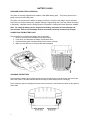
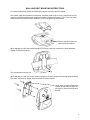
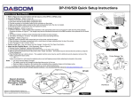
LOADING PAPER
The procedure for loading paper is as follows:
1.
2.
3.
Slide the Lid Release Button forwards until the Lid springs open.
Unwind a small amount of paper from the roll and Insert the Paper Roll into the Printer.
Close the Lid down, and the paper is loaded.
After loading, check that the paper advances properly, and tear off any excess by pulling the paper
sharply towards you across the serrated tear bar. In the event of a jam or other paper loading problem,
release the lid and straighten the paper before closing again.
PAPER OUT AND PAPER LID SENSORS
A reflective optical Paper Out sensor within the mechanism detects an out-of-paper condition, and/or
senses black marks to register with pre-printed forms. A mechanical sensor detects when the paper lid is
open.
By default, the printer enters Spooling mode automatically if either sensor becomes active. Spooling
mode is automatically exited, and any stored data printed, when new paper is loaded and the lid closed.
This behavior may be modified. Please refer to the Programmers’ Manual for details of how to configure
these functions.
6
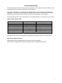
STATUS INDICATIONS
The Status Indicator at the front of the printer has a number of color combinations, which repeat in up to a
4-phase pattern to provide status information (see table below).
In summary, if the indicator is constant green it indicates that the printer is operating normally from its
battery pack. Flashing on and off indicates that Spooling mode is active and no printing can take place.
Orange advises the battery is being charged. Red warns of a low battery or other problem.
No light indicates that the unit is in sleep mode, has a discharged battery, or the battery is not connected.
Status Indicator Pattern Table
Pattern
Constant Green
Fast Flashing Green
Long Green - Short Red
Short Green - Short Red
Short Green - Long Orange
Long Orange Flashing
Fast Flashing Red
No light
Battery
Buffer Mode
Running
Normal
Running
Spooling *
Battery Low
Normal
Battery Low
Spooling *
Trickle Charging
Normal
Trickle Charging
Spooling *
Error Condition
Spooling (Printing prohibited)
Discharged, or in sleep mode
* (Spooling Mode may have resulted from Paper Out or Paper Door Open conditions)
Although this table may seem complicated, few applications will produce many of the combinations.
Other Status Indicator Patterns
Other patterns may be programmed into the printer by the system designer.
Please refer to the Programmer’s Manual for details of how to configure these functions.
7
PRINTER OPERATION AND PROGRAMMING
The LCM20 and LCM25 printers utilize a Fujitsu FTP-628MCL103 printer mechanism, with a fixed
(parallel) print head with 384 horizontally-arranged thermal elements. The paper is advanced by a
stepper motor, and printing takes place in a single dot row for each step of the paper. Each printed dot is
approximately 0.005” square. The printing speed and dot density are controlled according to the battery
voltage and the head temperature.
Various printing modes, including graphics, are invoked by 'Escape' sequences. Control codes and
status report protocols are described in detail in the Programmer’s Manual.
DATA BUFFER
The printer has a nominal 20k byte buffer to optimize throughput: this enables data to be received into the
buffer while previous lines are being printed. Printing will be initiated on receipt of a valid logical line of
data or a complete graphics pattern.
The buffer may be cleared by data command or by a hardware reset. A partially full line will be printed on
receipt of an appropriate control code, or after a programmable timeout delay.
SPOOLING MODE
Spooling mode can be entered by:
a command from the host;
Paper Out condition or Paper Lid open condition being sensed;
an error condition (e.g. head over temperature, battery over voltage, etc).
In spooling mode, the buffered data are stored without being printed until the mode is exited by:
a command from the host;
the 'causing condition' (e.g. Paper Out or Paper Lid open) being cleared;
the paper feed button being double-clicked.
CHARACTER PRINTING AND FONTS
The default 32-column character set is formed from a 24x10 dot matrix, and is based on the industry
standard IBM® character set Code Page 437. This character set has been modified to include the Euro
symbol (‘€’) at position 80H (128 Decimal), in place of the usual capital C with cedilla (‘Ç’).
Various combinations of single or double width, single or double height, inverted, underlined, and other
attributes may be mixed within a line.
Customized fonts may be created using a font editor utility, and downloaded to the printer. Only a single
custom font may be loaded in the printer at one time. Contact Printek Technical Support for more
information on the font editor utility.
GRAPHICS PRINTING AND OTHER PROGRAMMING MODES
Various dot-addressable graphics modes are supported, at up to 384 dots per line. The Windows driver
operates in the graphics mode. Refer to the Programmer’s Manual for full details of this and other
advanced programming modes.
8
INTERFACE DETAILS
RS-232 SERIAL INTERFACE (APPLIES TO ALL MODELS)
All LCM20 and LCM25 printers have an industry standard RS-232 interface. The default parameters are
9600 baud, 8 data bits, 1 stop bit and no parity. Other baud rates can be programmed by control codes,
or by using a setup utility. Contact Printek Technical Support for information regarding the setup utility.
Serial data is expected in standard RS-232C format with -12V meaning 'mark' or '1' and +12V a logical '0',
with reference to the common ground. The serial data output line, TxD, transmits XON/XOFF and status
information to the host at the same Baud rate and in the same format as the serial data input. The
hardware busy line is true (nominal -12V) when busy. Both serial output lines will relax to approximately
0V when the printer is in sleep mode, and the user must allow a short period after awakening before
relying on the values of these signals.
Some host equipment use a constant space condition (+12V) to indicate a reset condition or wait state.
Some battery powered host equipment present the same output signal when they go to sleep. The printer
can be set to ignore this condition as detailed in the Programmer’s Manual, but even then this type of host
behavior may result in one or more spurious characters being received and printed, or the printer may be
prevented from going to sleep.
IrDA INTERFACE (APPLIES TO LCM20 IRDA AND LCM25 IRDA ONLY)
IrDA models feature an Infra-Red window on the front of the body. It includes special hardware which
wakes the printer when any Infra-Red activity is detected. In order to reduce the occurrence of 'false
triggers', the sensitivity of this wake-up sensor is reduced. It may be necessary to bring the host IrDA
device fairly close to the printer before it will wake up.
Once awake, the printer will respond to communications from an IrDA compliant primary device. The
printer supports 'point-to-point' applications (i.e. one primary device and one secondary device). It
operates only as a secondary device, and cannot initiate a link between devices.
Once a link is established then the printer shows a red indicator through the IR window on the front. The
link will continue as long as the devices are maintained in line-of-sight and within operating range. While
a link is maintained, data may be exchanged freely between the two devices.
The protocols supported are as follows: IrPHY V1.0, IrLAP, IrLMP, IAS, TinyTP and IrCOMM 9-wire.
BLUETOOTH INTERFACE (APPLIES TO LCM20 BLUETOOTH AND LCM25 BLUETOOTH ONLY)
Bluetooth models include a class 2 implementation of the Panasonic PAN1440 module, which is
Bluetooth 1.1 compliant, and is certified to EN 300 328. The protocols and profiles supported are as
follows: LM, L2CAP, RFCOMM, SDP, TCS, SPP (Serial Port Profile).
The detail of how to establish a Bluetooth link and transfer data will vary greatly depending on the primary
host device. However, the process will generally involve the following stages:
i.
ii.
iii.
iv.
v.
Discovery of Bluetooth devices;
Discovery of the printer’s services;
Selection of the Serial Port Profile;
It may be necessary to Pair with the printer;
Connecting to the printer.
Note. The PIN for making a secure connection to the printer is pre-set to “1234”.
Usually the Bluetooth link is maintained for as long as the devices are within operating range. While the
link is active, data may be exchanged freely between the two devices. Occasionally the link may be lost,
in which case the user should re-initiate the link from the primary host as described above.
9
There is no facility to wake the printer over the Bluetooth link. The printer must be awake before a
Bluetooth link may be established and any data can be transferred to it via the Bluetooth interface.
Because of this, the default Sleep Period for the Bluetooth models is extended to 4 minutes.
10
CONNECTIONS AND EMC PRECAUTIONS
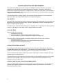
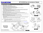
CONNECTOR DETAILS
The printer has two user connectors shown below:
Pin 1
Charger Input
RJ12 Combined Data Socket
CONNECTOR PINOUTS
Charger Input Socket Detail
Pin
Inner
Outer
Dimension (mm)
Inside Ø 2.5
Outside Ø 5.5
Function
Positive / Charger Input
Negative / 0V Common
The maximum insertion length is 12 mm.
RJ12 Combined Data Socket Detail
Pin
1
2
3
4
5
6
Signal
Direction
To Printer
To Printer
To Printer
To Host
To Host
---
Description
Optional Charger Input
Wake-up Input
RS-232 Rx data
RS-232 Tx data
RS-232 Busy
0V Common (RS-232 signal return and Charger return)
BATTERY CHARGER DETAILS
The printer monitors charge current into the printer, but does not regulate it in anyway. In order to fully
and safely charge the batteries, use only Printek Battery Charger Adapters.
Caution: This connection is for a current-regulated battery charger only. Do not connect a
standard voltage power supply. Serious damage may result from inappropriate
connections.
COMBINED DATA/CHARGER ADAPTOR CABLE
An optional serial data cable suitable for connecting the printer to a standard PC is available. This cable
features an integrated charger connector in the housing of the DB-9 connector. For trickle charging, the
charger may optionally be connected directly into the printer’s connector, or indirectly into the connector
in the data cable, thus giving the maximum system wiring flexibility.
11
The connections to a standard PC COM port are as follows:
DB-9 Pin
3
2
4
6&8
5
Name
TxD
RxD
DTR
CTS & DSR
SGND
Description (refers to PC)
Serial Data Output
Serial Data Input
Handshaking Output
Busy Input
Signal Common 0V
RJ12 Pin
3
4
2
5
6
The wake-up input (pin 2 of the RJ12) can be driven by a normal RS-232 handshaking output and
activates the printer when a positive voltage ('space' condition) is asserted. Connecting it to the PC DTR
signal wakes the printer when the COM port is 'opened'. It may alternatively be tied to a positive voltage
in the range +3V -> +12V to keep the printer awake permanently. In this case, the printer will 'attempt' to
go to sleep if the normal inactivity time-out elapses, but will merely reset and then re-start. This behavior
may be avoided by switching off the sleep period timeout.
EMC STATEMENT
The LCM20 and LCM25 printers are fully EMC (Electro-Magnetic Compatibility) compliant and are CE
marked accordingly. A Declaration of Conformity, in accordance with the EMC Directive 89/336/EEC
(and as amended) is available on request.
EMC Caution
System EMC compliance remains the responsibility of the system designer. It is recommended that
shielded cables are used; grounding arrangements will depend on the application.
12
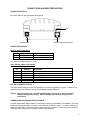
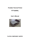
WALL AND BELT MOUNTING INSTRUCTIONS
A combined bracket/clip suitable for attaching the printer to a wall or belt is available
The bracket snaps into the bottom of the printer, and when used to clip to a belt, it may be secured by
using the supplied extended screw (replaces the battery compartment screw). Prior to use, two small
'break-outs' must be removed from the battery cover of the printer as shown below:
Remove the two 'break-outs'
using a small screwdriver.
When attaching to a belt, the bracket should be put on the printer first, and then the entire assembly
clipped over the belt as shown:
The securing screw may be used if required.
When attaching to a wall, the bracket must be located on the wall using screws and wall plugs as shown.
The printer may then be clipped into place and removed as required.
Use a finger or small screwdriver to
release the clip and then gently lift
the printer to remove from the wall
bracket.
13
GETTING STARTED
You may find that you can connect the printer to your Personal Computer (PC), and everything works
perfectly the first time. However, there are many variables, and the following guide may help if you find
you need some assistance. These are only suggestions, and may not work with all PC’s.
CONNECTING TO A PC – A CHECKLIST
First, MAKE SURE THE PRINTER IS OPERATIONAL
Make sure that the battery pack is connected. Remember that operation from the charger alone is not
possible: a battery pack must always be installed. Also remember that battery packs are normally
supplied disconnected and discharged. They should be connected and then fully charged before
use (e.g. trickle charged for at least 15 hours).
Wake the printer up by pressing the Paper Feed button once and releasing it. The Status Indicator
should light; if it does not, the battery may be discharged (or not connected correctly): connect the
charger, and the status indicator will come on.
When the printer is awake, load paper and then press the feed button to check that paper feeds. Press
the paper feed button again twice in quick succession (like double-clicking a PC mouse) and the printer
should print a self-test message. This will show that the printer is operational, and also reports how the
printer’s serial data interface is configured.
Next, CONNECT THE PRINTER TO THE PC
The back panel of a PC typically includes several D-type (keystone-shaped) connectors. One of these is
usually:
DB-9 Plug (male):
COM1: Serial port for mouse, modem, serial printer, etc
You can use any available serial port for the printer. COM1: is assumed in what follows, as most likely to
be available.
You will need a suitable cable. Use either a standard cable from Printek (see Section ‘Combined
Data/Charger Adaptor Cable‘), or make up your own using the information in the same section.
Now you will need to SET UP YOUR COMPUTER’S SERIAL PORT to match the printer (it is also
possible to change the printer’s settings, but not until you have established communication with the
computer).
Your proposed application program may have a way of doing this, or you can get to the DOS prompt [e.g.
C:\>] and type the following command line (assuming you have connected the printer to COM1:):
MODE COM1:9600,N,8,2 [RETURN]
This will set up the port (COM1:) to 9600 baud, No parity, 8 data bits, and 2 stop bits which is the default
setting for the printer.
Now, SEND SOME DATA TO THE PRINTER from your computer. An easy way to do this from the
DOS prompt is to type:
DIR >COM1: [RETURN]
This should send a directory listing to the printer. The lines will probably overflow, but it will at least show
that the communication between the computer and the printer is working.
Alternatively, in Windows, use the TERMINAL program to send some text to the printer.
14
WINDOWS™ PRINTER DRIVERS
A Windows driver specifically written for the printer is available and can be downloaded from
www.printek.com. It may be necessary to adjust some settings in your Application to produce the desired
result.
It is important to recognize that other Windows printer drivers, even for ESCPOS compatible printers, may
not work with the LCM20 or LCM25, as they format everything as dot graphics patterns, in a way which is
unique to each kind of printer. The Windows “Generic Text Only” printer driver should, however, work in a
limited manner.
Various applications and Tool Kits which fully support the LCM20 and LCM25 are available for PDA’s and
other Pocket PC platforms from www.fieldsoftware.com. When using these tools, select the Able
Systems AP1300/AP1310.
YOUR APPLICATION PROGRAM
Once communications between your computer and the printer have been established, you can try driving
the printer from your application program. As referred to in the Programmer’s Manual, the printer has a
control code set based on the EPSON ESCPOS protocol. Many of the commands are as closely
compatible as they can be, given the mechanical differences between printers, but if the application
program was originally written for another printer, it may need to be modified.
TECHNICAL SUPPORT
You may contact Printek Technical Support for assistance at 800-368-4636.
15