1
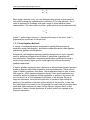
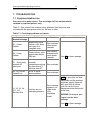
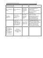
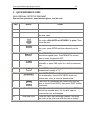
User Guidelines & Standard Operating Procedure for the Beckman Avanti J-30I High Performance Centrifuge Centrifuge Standard Operating Procedure ii TABLE OF CONTENTS DISCLAIMER ................................................................................ iv ACKNOWLEDGEMENTS .....................................................................v 1. INTRODUCTION........................................................................1 1.1 Purpose of the Standard Operating Procedure .............................1 1.2 Centrifugation Theory ..........................................................1 1.2.1 Centrifugation Methods...................................................2 1.2.2 Rotor Selection ............................................................3 1.3 Instrumentation .................................................................4 2. POTENTIAL HAZARDS.................................................................7 3. PERSONAL PROTECTIVE EQUIPMENT ...............................................8 4. SPILL AND ACCIDENT PROCEDURES ................................................9 4.1 Accidents .........................................................................9 4.2 Spills ..............................................................................9 4.2.1 Spills Inside the Centrifuge ..............................................9 4.2.2 Spills Outside the Centrifuge ............................................9 5. WASTE DISPOSAL PROCEDURES ................................................... 11 6. PROTOCOL........................................................................... 12 6.1 Sample Preparation........................................................... 12 6.2 Running the Centrifuge ...................................................... 13 6.3 After Completing a Run ...................................................... 15 7. TROUBLESHOOTING ................................................................ 16 7.1 Equipment Malfunction ...................................................... 16 8. PREVENTATIVE MAINTENANCE .................................................... 19 8.1 Daily ............................................................................ 19 8.2 Weekly.......................................................................... 19 8.3 Monthly ......................................................................... 19 8.4 Three Months .................................................................. 19 8.5 Six Months...................................................................... 19 8.6 Annually ........................................................................ 19 9. QUICK REFERENCE GUIDE.......................................................... 20 10. REFERENCES ...................................................................... 21 Centrifuge Standard Operating Procedure iii APPENDIX 1: ARABIDOPSIS CHLOROPLAST ISOLATION AND CHLOROPHYLL DETERMINATION.......................................................................... 22 APPENDIX 2: CENTRIFUGE USER LOG.................................................. 25 APPENDIX 3: PREVENTATIVE MAINTENANCE LOG .................................... 27 Centrifuge Standard Operating Procedure iv DISCLAIMER The materials contained in this document have been compiled from sources believed to be reliable and to represent the best opinions on the subject. This document is intended to serve only as a starting point for good practices and does not purport to specify minimal legal standards. No warranty, guarantee, or representation is made by Laurier as to the accuracy or sufficiency of information contained herein, and Laurier assumes no responsibility in connection therewith. v Centrifuge Standard Operating Procedure ACKNOWLEDGEMENTS The following individuals of Laurier contributed to the writing, editing, and production of this manual: Gena Braun (Instrumentation Technician); Stephanie Kibbee (Environmental/Occupational Health and Safety Office); Arthur Szabo (Chemistry). This manual was prepared for Laurier. Any corrections, additions or comments should be brought to the attention of the Instrumentation Technician at 519-884-0710 ext. 2361. Revised: April 2009 Revision: 3 Centrifuge Standard Operating Procedure 1 1. INTRODUCTION 1.1 Purpose of the Standard Operating Procedure This standard operating procedure (SOP) is NOT a substitute for training and/or reading the appropriate manuals before use. All principle investigators and supervisors must document that training has been received by students and staff who will be using the centrifuge. A list of authorized users will be kept by the Instrumentation Technician in SR314A. This SOP is intended to promote consistent and safe use of the Beckman Avanti® J30I centrifuge within the Faculty of Science. This SOP covers the potential hazards, personal protection requirements, spill and accident procedures, waste disposal considerations, and instrument operation for the Beckman Avanti J30I centrifuge [henceforth referred to simply as the centrifuge]. 1.2 Centrifugation Theory The following centrifugation theory is summarized from the Basics of Centrifugation, Cole Parmer Technical Library. The primary objective of centrifugation is to accelerate the rate of sedimentation in a sample. Under normal gravitational forces, particles in solution will gradually settle based on density, size, and mass. For dense particles like small pebbles this happens very quickly; however, for very small particles, such as cellular organelles or macromolecules like DNA and RNA, settling by gravity happens far too slowly to be useful. A centrifuge is therefore used to accelerate settling by spinning samples and creating forces that are over 500,000x times stronger than gravity (e.g. 500,000 x g is called the “relative centrifugal force”). Centrifugation can be used for a variety of applications, including pelleting, purification of cellular components, and density gradient separations. Pelleting simply creates a hard-packed concentration of particles at the bottom or along the side of a tube. Pelleting efficiency (k) is a measure of the time it takes to pellet a given sample in a specific rotor, so rotors with a lower “k” will pellet a sample in a shorter time. To compare pelleting time between two different rotors, use the following formula: 2 Centrifuge Standard Operating Procedure T1 T2 k1 k 2 When using a specific rotor, you can determine how quickly a given particle will pellet by using the sedimentation coefficient (S) for that particle. The Svalue is expressed in Svedberg units and a larger S-value indicates faster sedimentation. The time taken to pellet a given particle can be determined by: T k S where T= pellet time in hours. k = pelleting efficiency of the rotor, and S = sedimentation coefficient of the particle. 1.2.1 Centrifugation Methods A variety of methods have been developed to enable different types of separation using centrifugation, and these include differential centrifugation and density gradient centrifugation. Differential centrifugation separates particles based on size, and is typically used for pelleting and partial purification of subcellular organelles and macromolecules. Subcellular component purification is achieved by using a series of successively higher g-force centrifugations followed by density gradient separations. A density gradient separation uses continuous or discontinuous layered gradient media to separate subcellular organelles and macromolecules. There are two types of density gradients: Rate zonal, which separates based on size or mass, and isopycnic, which separates based on density. Rate zonal separations are commonly applied to separate cellular organelles or proteins, and cannot be run too long or all of the components will pellet at the bottom. During an isopycnic separation, each particle sinks until it reaches a layer where the density of the medium is the same as the density of the particle. In this case the centrifugation run must be run long enough to ensure that all particles have separated, and excessive run times will not have an adverse affect on the separation. Cesium chloride separation of nucleic acids is an example of an isopycnic separation. 3 Centrifuge Standard Operating Procedure Table 1-1: Media suitability for density gradient separations applications (Basics of Centrifugation, Cole Parmer Technical Library) Gradient Media Cells Viruses Organelles Nucleoproteins Macromolecules Sugars Limited use Good Good Limited Use Not suitable Polysaccharides (e.g. Ficoll) Good for some applications Good for some applications Good for some applications Not suitable Not suitable Colloidal Silica (e.g. Percoll) Good Limited use Good Not suitable Not suitable Iodinated media (e.g. Nycodenz) Excellent Good for some applications Excellent Good Limited use Not suitable Good for some applications Not suitable Good for some applications Excellent Alkali metal salts (e.g. CsCl) 1.2.2 Rotor Selection There are three main rotor types for any centrifuge: swinging bucket, fixed angle, and vertical or near-vertical. Table 1-2 lists the suitability of each rotor for various applications. Swinging bucket rotors contain hinged buckets which swing out to a horizontal position when the rotor is in motion. This type of rotor provides a longer path length for settling than fixed angle or vertical tube rotors, and it is particularly useful for density gradients. Swinging bucket rotors are generally inefficient for pelleting. Fixed angle rotors hold sample tubes at a specific angle and are all purpose rotors. They are ideal for pelleting bacteria, yeast, and mammalian cells and can be used for isopycnic density separations. Vertical rotors hold sample tubes completely vertical or nearly vertical throughout a run. These rotors are ideal for isopycnic separations of DNA, RNA, and lipoproteins, but are not useful for pelleting. 4 Centrifuge Standard Operating Procedure Table 1-2: Rotor suitability for various applications applications (Basics of Centrifugation, Cole Parmer Technical Library) Type of rotor Type of Separation Pelleting Rate-zonal Sedimentation Isopycnic Good for macromolecules Fixed Angle Excellent Limited Swinging Bucket Inefficient Good Vertical Not suitable Good Poor for cells and organelles Good for cells and organelles Excellent Compatible Tube Types Thick wall open top and thin wall sealed Thick or thin wall open top Thin wall sealed Rotor speed can be measured as revolutions per minute, RPM, or as relative centrifugal force (RCF). RCF and RPM are related as per the following equation: RPM RCF 11.17 Rmax 1000 2 where Rmax is the maximum radius from the axis of rotation in centimeters. For example, for a swinging bucket rotor, this would be the bottom of the bucket when it is in a horizontal position. 1.3 Instrumentation The J301 centrifuge operates under vacuum and the temperature can be set between -20°C and 40°C. Each run can be set up manually, or run using a preset program. The ultracentrifuge can reach speeds up to 100,000 RPM depending on the rotor used. There are three different rotors available for this instrument: a JS 13.1 swinging bucket, a JLA 10.500 fixed angle, and a JA 30.50 Ti fixed angle. The JS and JLA rotors are composed of anodized aluminum and will corrode very quickly if scratched, making them unusable, so treat these rotors with extra care. The JA Ti rotor is composed of titanium and is less susceptible to corrosion, but it should still be used and cleaned carefully. Table 1-3 lists the properties of each rotor, and Table 1-4 lists the types of tubes that can be used in each rotor. Note: Open top tubes should be filled within 3 mm of the top to provide adequate support for the tube; only thickwall tubes can be run at ½ full. 5 Centrifuge Standard Operating Procedure Table 1-3: Rotors available for the Avanti J-30I centrifuge Rotor Maximum RPM and RCF (Critical Speed Range) k 30,000 RPM 108,860 x g JA 30.50 Ti Fixed 34o Angle 280 Tube Dimensions, Number of Tubes x Maximum Tube Volume Tubes: 25 X 105 mm Samples: 8 x 40 mL (600-800 RPM) Suitable Applications Pelleting of cells, cell particles, and subcellular fractions. 10,000 RPM 18,600 x g JLA 10.500 Fixed 20o Angle (600- 800 RPM) 13,000 rpm 26,500 x g JS 13.1 Swinging Bucket 2,850 (400-1450 RPM) Tubes: 69 x 160 mm Samples: 6 X 465 mL 1,841 Tubes: 29 x 104 mm Samples: 6 X 45 mL Large volume pelleting of cells, cell particles, and subcellular organelles. Density gradient separation or pelleting of tissue homogenates, cells, and subcellular particles. 6 Centrifuge Standard Operating Procedure Table 1-4: Tubes that can be used in each rotor1 Rotor Tube JA 30.50 JS 13.1 JA 10.500 Tube Type Polycarbonate with cap Polyallomer with cap Thickwall polycarbonate, no cap Thickwall polypropylene, no cap Polycarbonate, screw cap Polyallomer, screw cap Thickwall polycarbonate, snap cap Thickwall polypropylene, snap cap Polycarbonate, screw cap Polyallomer, screw cap Thickwall polycarbonate, snap cap Thickwall polypropylene, snap cap Polycarbonate with cap Polypropylene with cap 357000 357001 Maximum Volume (ml)2 40 40 363647 25 30000 357007 25 30000 357002 357003 40 40 25000 25000 363664 36.5 25000 357005 36.5 25000 357002 357003 45 45 13000 13000 363664 45 13000 357005 45 13000 361390 361691 465 445 10000 8000 Part Number Maximum Speed (rpm)3 30000 26000 1. This table only lists tubes that do not require an adaptor. Several different tubes can also be run with the appropriate adaptor. Please contact the Instrumentation Technician for assistance if the tubes listed in above the table do not suit your needs. 2. Tubes must be run at least half full. 3. The maximum speeds listed are based on water samples. Samples of higher density or in a different solvent may require speed reductions to prevent tube failure. Use the following formula to adjust the maximum rotor speed for samples of different density: Reduced Maximum Speed ( Original Maximum Speed) 1.2 g / ml density of tube contents Centrifuge Standard Operating Procedure 7 2. POTENTIAL HAZARDS NEVER CENTRIFUGE MATERIALS THAT ARE CAPABLE OF DEVELOPING FLAMMABLE OR EXPLOSIVE VAPOURS. DO NOT CENTRIFUGE RADIOACTIVE, PATHOGENIC, OR TOXIC SUBSTANCES IN THIS CENTRIFUGE. Centrifuges have the capacity to be VERY dangerous, and care must be used each time a run is set up. Do not bump, lean on, or attempt to move the ultracentrifuge while it is running. Tubes and bottles must be inspected before each use to make sure that they are in excellent condition, and it must be verified that the tubes in use can withstand the g-force generated by the run conditions selected; small scratches in glass or polycarbonate tubes can cause failure at high g-forces, resulting in the loss of the sample, an imbalanced rotor, and potential damage to the ultracentrifuge. Tubes may display crazing: small cracks that do not penetrate all the way through the wall, but if a crack approaches the outer wall of the tube, discard it. Do not use a tube that has been come yellow or brittle with age. A tube may fail if it is not the correct shape, or if an incompatible solvent/tube-material combination is used. It is recommended that only tubes specifically designed for this ultracentrifuge and a given rotor be used. Use of other tubes may void the instrument and rotor warranties. Use only the rotors listed in Table 1-3 in the Avanti J30I centrifuge. Rotors should never be run empty; at least two filled tubes should be run in the rotor, even if they are just water filled blanks during a rotor cooling run. Do not attempt to set the speed higher than the maximum rated speed of the rotor in use. NEVER attempt to stop a rotor by hand or open the door while the ultracentrifuge is running. DO NOT USE any sharp tools on the rotors as this will lead to scratching and corrosion. Samples MUST be run balanced, both in position and individual mass. This can be accomplished by opposing two equal weight tubes/bottles on opposite sides of the rotor. Equal weight must be determined including tube closures using the pan balance or an electronic balance; balance tubes to within 1 gram. Rotor balance can also be obtained by equally-spacing an odd number of tubes around the rotor (see Figure 2-1). If you only have one sample, you must use a second tube/bottle containing a liquid with a similar density and ensure that the weights/volumes of the two vessels are the same. The ultracentrifuge has an imbalance detector, and will automatically end the run if a rotor is out of balance. However, serious damage may have already occurred, so DO NOT rely on the imbalance sensor to stop the rotor if you load imbalanced samples. 8 Centrifuge Standard Operating Procedure When running biological samples (not pathogens or toxic substances, as stated above), use sealed or capped tubes to minimize aerosol generation. In the event of a power failure, contact the Instrumentation Technician for assistance to retrieve samples from the ultracentrifuge. 1 1 1 2 1 1 2 2 1 1 1 3 3 1 2 Figure 2-1: Methods for balancing a rotor. In this example, if three tubes are placed in the rotor they must all be the same weight. 3. PERSONAL PROTECTIVE EQUIPMENT Material to be centrifuged may contain potentially infectious or hazardous material, so standard laboratory protective equipment must be worn (latex or nitrile gloves, approved safety glasses, lab coat). Closed-toe and heel footwear constructed of resistant material is also required for laboratory activities. See the WLU Laboratory Health and Safety Manual for additional information on personal protective equipment: http://www.wlu.ca/documents/23120/Laboratory_Health_%26_ Safety_Manual__Feb_2007_Final.pdf. Centrifuge Standard Operating Procedure 9 4. SPILL AND ACCIDENT PROCEDURES 4.1 Accidents If you notice anything unusual concerning centrifuge operation (smells, noises, etc.) stop the centrifuge immediately and contact the Instrumentation Technician. All incidents must be reported to the Instrumentation Technician and if applicable, a student’s supervisor. The Instrumentation Technician will insure that all accidents, incidents and near misses are reported to the Environmental/Occupational Health and Safety (EOHS) Office via the WLU Employee Accident/Incident/Occupational Disease Report form (www.wlu.ca/eohs/forms). To meet regulatory requirements, these forms must be submitted to EOHS within 24 hours of occurrence, with the exception of critical injuries, which must be reported immediately to the EOHS Office by telephone. Critical injuries include any of the following; place life in jeopardy, produce unconsciousness, result in substantial loss of blood, involve fracture of a leg or arm but not a finger or toe, involve amputation of a leg, arm, hand or foot, but not a finger or toe, consist of burns to a major portion of the body, or cause the loss of sight in an eye. Additional details regarding incident reporting can be found in the WLU Accident Incident Procedure (www.wlu.ca/eohs). 4.2 Spills 4.2.1 Spills Inside the Centrifuge Spills inside the centrifuge may occur from the failure of a tube or rotor. No operation of the centrifuge is allowed until the spill is cleaned up. 2. Review the MSDS, if not done so before commencing the analysis, to determine the protective equipment, spill cleanup, and disposal protocols that are necessary. 3. Wear appropriate personal protective equipment, and contain the spilled material first using an appropriate spill kit. 4. Report the spill to the Instrumentation Technician, who will advise the user on the best way to clean up the spill. 5. Record the spill and cleanup procedure in the log book. 4.2.2 Spills Outside the Centrifuge The WLU Laboratory Health and Safety Manual provides detailed instructions for dealing with major and minor spills. Do not attempt to clean up a spill if you have not been properly trained, or if you are unsure of the proper procedures. Before using ANY hazardous materials, make sure you understand the proper clean-up procedure. The Environmental/Occupational Centrifuge Standard Operating Procedure 10 Health and Safety Office is also available to provide guidance at ext. 2874. The guidelines below are summarized from the WLU Laboratory Health and Safety Manual. Determine if the spill is a major or minor spill (see Table 4-1). 1) For major spills: a) Evacuate the lab, close the doors, restrict the area, and notify others in the area of spill, including your supervisor and the Instrumentation Technician if possible. b) Call ext 3333 (Community Safety and Security). c) Activate the fire alarm if there is risk to the safety of other people in the building. d) Be available to provide technical information to emergency responders. 2) For minor spills: a) Attend to injured or contaminated personnel. b) Restrict the area and notify others in the lab of the spill, including your supervisor and the Instrumentation Technician if possible. c) Take action to minimize the extent of the spill. d) If flammable material is involved, turn of ignition sources (power, Bunsen burners). e) Select and wear all appropriate personal protective equipment. f) It is the responsibility of the user of the hazardous material to clean up the spill if he/she feels it is safe to do so. g) All personal protective equipment must be disposed of correctly, and must not be worn outside the laboratory. h) Apply spill pillow/pads or other absorbent material, first around the outside of the spill, encircling the material, then absorb to the center of the spill. i) Dispose of all materials used to clean up the spill in a sealed container. j) Label and dispose of all bags or containers as hazardous waste. 3) For chemical spills on the body: a) Remove all contaminated clothing. b) Flood exposed area with running water form a safety shower for at least 15 minutes. c) Have another individual contact 9-911 and ext 3333 to obtain medical attention. d) Report the incident to your supervisor and the Instrumentation Technician. 4) For chemicals splashed in the eye(s): a) Immediately rinse eyeball and inner surface of eyelid with water continuously for 15 minutes. Forcibly hold eye lid(s) open to ensure effective wash behind eyelids. b) Have another individual contact 9-911 and ext 3333 to obtain medical attention. 11 Centrifuge Standard Operating Procedure Table 4-1: Guidelines for classification of a major spill Material Air and water reactive materials Flammable liquids Combustible liquids Non-flammable organic liquids Concentrated acids Concentrated bases and alkalis Mercury Oxidizers Highly toxic, highly malodorous material Low hazard material Compressed gas leaks Quantity All quantities Greater than 4L Greater than 4L Greater than 4L Liquids greater than 1L Solids greater than 1kg Liquids greater than 1L Solids greater than 1kg Greater than 30 ml Liquids greater than 1L Solids greater than 500g Liquids greater than 100 ml Solids greater than 50g At the discretion of laboratory personnel If the leak cannot be stopped by closing the valve on the gas cylinder 5. WASTE DISPOSAL PROCEDURES Use of the centrifuge itself does not result in waste; HOWEVER, all WHIMIS and Department guidelines must be followed for disposal of the substance to be centrifuged. See the WLU Laboratory Safety Manual. Centrifuge Standard Operating Procedure 12 6. PROTOCOL 6.1 Sample Preparation 1. The rotors for the Beckman Avanti J30-I are stored in the cold room (SR412A). 2. Check the rotor before using: a. Make sure that it is clean and dry. If it is not clean, you must clean it before using it and report the problem to the Instrumentation Technician. Liquids and dried samples that are left in the buckets can cause corrosion and make the rotor unbalanced. b. Make sure that the metal threads on the rotor are clean and lightly greased. c. Check the o-rings to make sure they are present and have a light coating or silicone vacuum grease. If any o-rings are missing, contact the Instrumentation Technician before using. d. Examine the pins for damage. If new damage is apparent, consult with the Instrumentation Technician before using. 3. Check the chemical compatibilities of the materials to be used in the rotor (Refer to Appendix A in the Rotor User manual on the side of the centrifuge) 4. Samples in the rotor must be balanced: a. Load opposing buckets or carriers with the same type of labware containing the same amounts of fluid of equal density; b. Weight samples on a balance in your lab, or on the balance beside the centrifuge (SR416), and place equally weighted samples across from one another in the centrifuge (See Section 2 for more detail). i. Do not conclude that tubes are balanced by sight or volume; ii. When using rotor sleeves, balance them along with the tubes; iii. If necessary, use "water blank" tubes to balance sample tubes of unequal weigh. 13 Centrifuge Standard Operating Procedure 6.2 Running the Centrifuge 1. Check the log book first to ensure that the centrifuge is functioning properly (i.e. no serious problems are listed). 2. Turn on the power switch; 3. Use the foot pedal at the front of the centrifuge to open the centrifuge lid; 4. If using the JA 30.50 rotor: a. Install the rotor body, making sure that the rotor alignment pins are properly positioned between the teeth on the centrifuge drive shaft (Figure 6-1); if the pins are not aligned properly massive damage can result. b. Load samples into the rotor body, making sure that all samples are properly balanced (see above). c. Place the rotor lid on the rotor body. Tighten the larger ‘daisy-type’ knob on the lid to fasten the rotor lid securely on the rotor body (Figure 6-2). Press down and tighten the smaller knob to fasten the rotor to the drive shaft of the centrifuge (check this by lifting up on the rotor). Do not over tighten the knobs; Figure 6-1: Drive Shaft Figure 6-2: JA 30.5 lid d. Note: Because of the sealing system used in this rotor, it may be loaded and the lid sealed (with the daisy knob) in a controlled area (containment hood etc.) and then transported safely to the centrifuge. Extreme care, however, must be taken to ensure that the rotor alignment pins and the centrifuge drive shaft are properly positioned relative to each other. The smaller, non-daisy knob is still used to tie the rotor securely to the centrifuge drive shaft. e. Close the centrifuge door only when you are sure the samples and rotor have been correctly balanced and attached to the centrifuge. f. The centrifuge will automatically recognize the JA 30.50 rotor. 5. If using the JA 13.1 rotor: a. The buckets or carriers must be loaded symmetrically with respect to their pivotal axes (the pivotal axis runs parallel to the crossbar). b. The rotor should be loaded symmetrically with respect to its center of rotation. c. Carefully lower the rotor yoke straight down onto the drive spindle. Rotate it by hand until the drive pins seat between the teeth on Centrifuge Standard Operating Procedure 14 the drive spindle hub. There are arrows on the rotor to direct placement of the rotor on the spindle. d. When the yoke is correctly seated, secure it to the drive spindle hub by hand tightening the tie-down knob. If the rotor is left in the centrifuge between runs, tighten the knob before each run. e. Close the centrifuge door only when you are sure the samples and rotor have been correctly balanced and attached to the centrifuge; f. The centrifuge will not automatically recognize the JA 13.1 rotor; it must be set using the “ROTOR” key on the control panel, and a soft key to select the rotor name. Press “ENTER”; 6. If using the JLA 10.500 rotor: a. Install the rotor body, making sure that the rotor alignment pins are properly positioned between the teeth on the centrifuge drive shaft; if the pins are not aligned properly massive damage can result; b. Make sure all of the rotor buckets are firmly seated in the rotor body (even if only using 2 buckets, all must be in place and capped); c. Load samples into the rotor buckets, making sure all samples are properly balanced; d. Hand-tighten a closure onto each bucket (do not use any wrench or tool, this will result in over-tightening and potentially damage the buckets); e. Place the lid on the rotor and use the knob to securely fasten the lid/rotor assembly to the centrifuge drive shaft (check this by lifting up on the rotor); f. Close the centrifuge door only when you are sure the samples and rotor have been correctly balanced and attached to the centrifuge; g. The centrifuge will automatically recognize the JLA 10.500 rotor. 7. Enter the speed required for the run. Press the “SPEED” button, choose RPMs (revolutions per minute) or RCF (relative centrifugal force; the measurement of the force applied to a sample within a centrifuge) using the soft keys, and then enter the desired number. Press “ENTER”; 8. Set the time required for the run. Press the “TIME” key, and then choose the type of time needed using the soft keys, the choices being Hours:Minutes (HH:MM), Hold (centrifuge will spin until you turn it off), or 2t mode (accumulated centrifugal force); if HH:MM or 2t mode is chosen, enter the appropriate numbers followed by “ENTER”; 9. Set the temp required for the run (typically it is set at 4 ˚C). Press “TEMP” and enter the desired temperature in degrees Celsius, followed by “ENTER”; 10.Set the acceleration rate. Press "A/D” and choose the appropriate soft key: “MAX” (full acceleration), “SLOW” (slow acceleration from 0-500 RPM, and then full acceleration) or “TIME” (acceleration from 0-500 RPM can be programmed for 1-10 minutes, followed by full acceleration). Press “Enter”; 11.Set the deceleration rate. Press ”A/D” once or twice (until the cursor blinks in the first digit of the “DECEL” field) and choose the appropriate soft key: “MAX” (full deceleration), “SLOW” (reduced deceleration from set speed to 500 RPM, and then about 2 minutes to come to a full stop), “TIME” (full deceleration from set speed to 500 RPM , and then deceleration from 500 to Centrifuge Standard Operating Procedure 15 0 RPM can be programmed for 1-10 minutes), or “OFF” (no brake is used, and the rotor can take up to 1 hour to coast to a stop). Press “Enter”; 12.Press “ENTER” , followed by “START”; 13.Stay with the centrifuge until full speed is attained. If you sense that the centrifuge is not running smoothly indicated by abnormal vibration, whining, or grinding noises, abort the run immediately and recheck the rotor lid and balance. Report all irresolvable problems to the Instrumentation Technician. 14.The run will finish when the required “TIME” parameter is met, or when “STOP” is pressed. Do not attempt to open the lid until the centrifuge has come to a complete stop. 15.When finished, turn off the centrifuge and clean the chamber and rotor as directed in Section 6.3. 6.3 After Completing a Run 1. Accurately record the centrifuge/rotor use in the logbook provided. This information is essential for rotor down rating and centrifuge servicing; 2. Ensure the cleanliness of the rotor and centrifuge; a. Any condensate or spills inside of the centrifuge chamber must be cleaned with a mild detergent and wiped dry with a sponge or paper towel (cleaning materials located in the cupboard beside the centrifuge). b. Metal rotors in contact with moisture for extended periods of time will corrode and become useless. It is very important that the rotor is left clean and dry after use. Dry the rotor thoroughly. i. If spilled material is left in the rotor, it could imbalance the rotor on the next run, spread material throughout the centrifuge, cause a serious rotor failure, and cause the rotor itself to corrode. ii. If a spill occurred, rotors should be cleaned with mild soap and water (no abrasives) and an all-plastic rotor-cleaning brush (any metal will scratching the rotor). These items are available in the cupboard beside the centrifuge. iii. After the rotor has been cleaned and well rinsed with DI water, ensure that it has dried completely (upside down or with a soft sponge or paper towel) before storing in the cold room. 3. Rotors, lids, and canisters must be stored upside down in the cold room (lids and caps should be removed). If you had any problems or concerns regarding the operation of the centrifuge, please contact the Instrumentation Technician immediately (SR314A, x2361). 16 Centrifuge Standard Operating Procedure 7. TROUBLESHOOTING 7.1 Equipment Malfunction Users are not to make repairs. The centrifuge shall be maintained and repaired by qualified persons only. Table 7-1 lists some of the common minor problems that may occur and recommends the appropriate action for the user to take. Table 7-1: Centrifuge problems and causes. Diagnostic Number/Message Problem Result P1 – Power Failure Momentary power failure; rotor does not come to a complete stop Run continues when power resumes P2 – Power Failure Power failure; rotor speed drops below 500 rpm Run restarts automatically when power resumes C1 – Rotor temp exceeds 4C above set H4, H6, and H9 – Speed Error L1, L2, L5, L6, L11, L12 – Reclose Door Rotor temperature exceeds temperature setting by more than 4oC but less then 8oC Accel or decel speed problem Latches are not operating properly Recommended Action Press CE to clear message. Run continues Run continues Error message appears; run shuts down with maximum break Press on the door and press DOOR. If you close the door repeatedly and the problem continues, gently clean the latch area with a lintless swab. Be careful not to damage sensitive electronics in the area. WARNING: Do not put your fingers into the latch openings. Press CE to clear message. 17 Centrifuge Standard Operating Procedure Diagnostic Number/Message D13 – No rotor in chamber or drive problem Problem The is no rotor installed or the drive belt is loose or broken Result Run shuts down with maximum brake F1 and F2 – FRS, call service Required vacuum level not reached in allowed time Run shuts down with maximum break R1 and R2 – Rotor, ID problem No magnets identified, or magnets incorrectly identified Run continues, speed may be decreased. R3, R4, and R8 – Rotor, speed derated R5 and R6 – No rotor match The entered rotor number is not the same as the rotor identified The system cannot identify the rotor If identified rotor speed maximum is lower than entered maximum, the speed will be reduced to the rated maximum of the installed rotor Run shuts down with maximum break Recommended Action Install rotor per the applicable rotor manual. If the message occurs when the rotor is installed correctly, call the Instrumentation Technician. Check and clean door sealing area and door gasket. Wipe any ice and excess moisture from chamber. If the problem persists, call The Instrumentation Technician. Press CE to clear message. If the problem repeats, check rotor magnets, or call the Instrumentation Technician. Press CE to clear message. Enter the correct rotor entry code. Make sure the rotor in use is a compatible Beckman Coulter rotor. If the problem persists, call the Instrumentation Technician. 18 Centrifuge Standard Operating Procedure Diagnostic Number/Message Problem Result R9 – Calibration error Rotor calibration error Run shuts down with maximum brake I1 – Rotor imbalance Rotor load is severely out of balance Run shuts down with maximum brake During lowtemperature runs (near -10oC) ice forms around the door opening Door will not open at the end of a run - C2, C3, C5, T1 through T4, D1 through D12, D14, D15, S1 through S14, H1 through H3 H5, H7, H8, H11 Call the Instrumentation Technician, ext 2361 Recommended Action Make sure the rotor in use is a compatible Beckman Coulter rotor. If the problem persists, call the Instrumentation Technician. Make sure that tubes or bottles are loaded symmetrically in the rotor. With swinging buckets, remove the buckets and lubricate the pivot pins. To minimize icing, wipe moisture from the chamber, the chamber gasket, and the inner door surface before each run. Keep the door closed as much as possible. Centrifuge Standard Operating Procedure 19 8. PREVENTATIVE MAINTENANCE Users are not to perform maintenance. These procedures are carried out by the Instrumentation Technician. 8.1 Daily - Check the centrifuge interior for condensation Check the log book for any problems or concerns 8.2 Weekly - Clean interior of centrifuge and drive hub with mild detergent or diluted Beckman 555 solution Check rotors for discoloration Grease the o-rings, gaskets and threads of the centrifuge, rotors, and canisters 8.3 Monthly - Clean and lubricate the rotor pins and bucket pin sockets 8.4 Three Months - Check the vacuum pump oil level and clarity 8.5 Six Months - Replace rotor o-rings and centrifuge gaskets if necessary 8.6 Annually - Check and install new air filter if required 20 Centrifuge Standard Operating Procedure 9. QUICK REFERENCE GUIDE WEAR PERSONAL PROTECTIVE EQUIPMENT Eye and face protection, heat resistant gloves, and lab coat Step Button Action 1 POWER Turn the power switch on (|). 2 Foot Pedal 3 4 5 Install the rotor according to the manual – insure that the rotor is BALANCED and SECURELY in place. Then close the door. ROTOR RPM/RCF 6 TIME 7 TEMP 8 9 Press the foot pedal to unlock the chamber door; lift the door open. ACCEL/DECEL ENTER START 10 Foot Pedal 11 Clean and Store If the centrifuge does not automatically recognize the rotor, press ROTOR and then choose from the list. Press RPM/RCF and use the keypad to enter the desired run speed (rpm). Press RPM/RCF a second time to enter the speed in RCF. Press TIME and use the keypad to enter the run time (HH:MM); or press TIME twice for a hold (continuous) run. Press TEMP and use the keypad to enter the desired temperature (usually 4˚C). Press ACCEL/DECEL and choose max, slow, or time for acceleration. Press ACCEL/DECEL twice and choose max, slow, or time for deceleration. Check that all parameters are correct and that the door is closed. Press ENTER, then press START (within 5 seconds). When the rotor stops (a tone sounds), press DOOR to unlock the chamber door, lift the door open to remove the rotor and samples. Clean the rotor and centrifuge chamber, and store the rotor in the cold room with the lids on loosely. Centrifuge Standard Operating Procedure 21 10.REFERENCES Beckman Coulter. 1999. JA 30.50 Ti Fixed Angle Rotor. Spinco Business Center of Beckman Coulter, Inc.; Palo Alto, California. Beckman Coulter. 2000. J-Lite JLA-10.500 Fixed Angle Rotor Assembly. JS-13.1 Swinging Bucket Rotor Manual. Beckman Coulter; Fullerton, California. Beckman Coulter. 2002. Avanti J-E Centrifuge Instruction Manual. Centrifuge Instrument Systems Development Center of Beckman Coulter, Inc.; Palo Alto, California. Beckman Coulter. 2002. Rotors and Tubes for Beckman Coulter J2, J6, and Avanti® J Series Centrifuges. Centrifuge Instrument Systems Development Center of Beckman Coulter, Inc.; Palo Alto, California. Beckman Coulter. 2007. JS-13.1 Swinging Bucket Rotor Manual. Beckman Coulter; Fullerton, California. Beckman Coulter. 2007. JS-13.1 Swinging Bucket Rotor Manual. Spinco Business Center of Beckman Coulter, Inc.; Palo Alto, California. Cole Parmer Technical Library. Basics of Centrifugation. www.coleparmer.com. Accessed March 20, 2009. Laboratory Health and Safety Manual. 2007. Wilfrid Laurier University Environmental/Occupational Health and Safety Office. University of Guelph, Department of Chemistry. 2002. Centrifuge Standard Operating Procedures. http://www.chembio.uoguelph.ca/sop/centrifuge_use.htm, Accessed Feb 27, 2007. Rotor pictures: http://www.beckmancoulter.co.jp/. Accesses Feb 27, 2007. Centrifuge Standard Operating Procedure APPENDIX 1: ARABIDOPSIS CHLOROPLAST ISOLATION AND CHLOROPHYLL DETERMINATION This procedure is based on a method used by the M. Smith lab, Oct 2007. Required Buffers 1M HEPES-KOH -add 119.15g HEPES to ~300 mL of milli-Q H20 -stir until dissolved; add milli-Q to 500 mL -Adjust pH to 7.5 using 5M KOH -Autoclave @ L30 HEPES SORBITOL Buffer (HS Buffer, 200 mL) 10mL 1M HEPES-KOH, pH 7.5 (50mM final) 12.02g Sorbitol (330mM final) -adjust pH to 7.5 w/ KOH, volume up to 200mL with milli-Q -store at 4C 2 x Grinding buffer (GB, 300 mL) 30mL 1M HEPES-KOH, pH 7.5 (100mM final) 36.07g Sorbitol (660mM final) 2.4 mL 0.5M EDTA (4mM final) 300μl 2M MgCl2 (2mM final) 600μl 1M MnCl2 (2mM final) 85% Percoll (50 mL) 42.5mL Percoll (85% final) 2.5mL 1M HEPES-KOH, pH 7.5 (50 mM final) 3.01g Sorbitol (330 mM final) 50μl 2M MgCl2 (2mM final) 400μl 0.5M EDTA (4mM final) 0.1g BSA 0.5 g Ascorbic acid (50 mM final) -Adjust pH to 7.5 with KOH; add milli-Q up to 50mL -store at -20C 40% Percoll (50 mL) 20 mL Percoll (40% final) 25 mL 2x GB 0.5g Ascorbic acid (50mM final) -Adjust pH to 7.5 with dilute HCl -Add milli-Q up to 50 mL -store at -20C 22 Centrifuge Standard Operating Procedure 23 10 x Import Master Mix (50 mM HEPES, 330 mM Sorbitol, 400 mM KOAc, 50 mM MgOAc) For 25 mL: 0.298 g HEPES 1.503 g sorbitol 0.981 g KOAc 0.268 g MgOAc Adjust pH to 8.0 using KOH Stored as 1 mL aliquots @ -20°C Part I: Chloroplast Isolation 1. Prepare equipment; a. thaw Percoll b. cool down centrifuge (put in JLA 10.5 rotor and spin with at least two water blanks at 1,000 x g for 5 min; rotor stored in cold room) c. put 500 ml centrifuge bottle on ice (w/ funnel and Miracloth) 2. Prepare 1x Grinding Buffer: a. To 125 ml of 2x GB add: i. 4.95 g ascorbic acid ii. 0.625 g BSA b. Add milli-Q to a volume of ~225 mL and adjust pH to 7.5 using KOH c. Bring volume up to 250 ml with milli-Q water d. KEEP ON ICE 3. Prepare 2 Percoll step gradients (in 50 ml centrifuge tubes): 7 ml of 85% Percoll on bottom, 8 mL of 35% Percoll on top. 4. Harvest green tissue by shaving off Arabidopsis tissue from the surface of the plates using a single-sided razor into a 600 mL plastic beaker. Avoid getting agar in the beaker. 5. Add ~200 mL of ice cold 1x grinding buffer to harvested tissue and homogenize using PowerGen homogenizer (@ setting 3, ~15 sec). 6. Filter homogenate through 2 layers of Miracloth into a pre-chilled 500 ml centrifuge bottle. 7. Centrifuge for 8 min, 1,000 x g, 4C (JLA 10.5 rotor) and decant SN (down drain). 8. GENTLY re-suspend pellet in ~8 ml of fresh, ice-cold, 1x Grinding Buffer. 9. Divide chloroplast suspension evenly between 2 Percoll step gradients using 10 mL pipette. 10.Centrifuge gradients @ 7,700 x g, 15 min, and 4C in swinging bucket rotor (JS13.1, in cold room) with SLOW acceleration/deceleration. 11.Aspirate top layer of broken chloroplasts and buffer (waste). 12.Collect lower band of intact chloroplasts using a Pasteur pipette and dilute in ~50 ml of HS buffer (put ~20 ml of HS in a centrifuge tube, collect C.P.s, Centrifuge Standard Operating Procedure 24 and then fill with HS), cover centrifuge tube with parafilm and gently invert 1x. 13.Centrifuge @ 1,000 x g, 6 min, 4C in swinging bucket rotor (JS13.1, MAX acceleration/deceleration). 14.Decant SN (can go down drain). 15.Re-suspend pellet in ~200-300 μl of HS buffer and transfer to 1.5 ml microcentrifuge tube, while estimating the total volume (using pipette). Part II: Chloroplast Concentration 1. Prepare reference sample: a. 10 μl HS buffer b. 990 μl 80% acetone 2. Prepare chloroplast sample: a. 10 μl intact chloroplast suspension b. 990 μl 80% acetone 3. Mix both samples by vortexing. 4. Centrifuge samples for 2 min @ max speed to pellet insoluble material. 5. Set the wavelength of the Cary 50 UV-Vis spectrophotometer to 652 nm, and blank with reference sample. 6. Read absorbance of chloroplast sample at 652 nm. 7. Calculate chlorophyll concentration using the following equation: chlorophyll concentration (mg/ml) = [A652/36] x DF; where A652 is the absorbance of the sample measured at 652 nm and DF is the dilution factor of the chloroplast sample (in this case the dilution factor is 100). 8. Dilute chloroplasts to a chlorophyll concentration of 1 mg/ml. Centrifuge Standard Operating Procedure APPENDIX 2: CENTRIFUGE USER LOG 25 26 Centrifuge Standard Operating Procedure DATE NAME EXT # SUPERVISOR ROTOR RUN TYPE DETAILS PROBLEMS / COMMENTS Centrifuge Standard Operating Procedure APPENDIX 3: PREVENTATIVE MAINTENANCE LOG 27 28 Centrifuge Standard Operating Procedure DATE NAME EXT # TYPE OF MAINTENANCE FREQUENCY OF MAINTENANCE (I.E. WEEKLY) PROBLEMS / COMMENTS