1
University of Mary Hardin Baylor
Submittal Transmittal
[For Subcontractor]
Project # 1905900
Telephone:
Date:
January 08, 2013
Fax:
1/8/2013
Transmittal No: 0517
Jay Vanadore
Transmitted To:
Transmitted By:
Berg Electric
4509 Freidrich Lane, Ste 105
Austin, TX 78744
Tel: 512.447.3800
Fax: 512.447.3811
Submittal Package No
Description
0001 - 27 13 43.53 - 1
Qty
Spec
001
1
27 13 43.5 00595
Company Name
Due Date
CATV System PD
Items
Cc:
Christine Fuentes
Turner Construction Company
2001 N. Lamar, Suite 100
Dallas, TX 75202
Tel: 214-721-8400
Fax: 214-721-8490
Item #
Rev Type
0
Description
Notes
Item Action
Product Data / Cut Sheet CATV System PD
Resubmittal
Contact Name
Copies
Fax Number
Approved
Notes
Remarks
Signature
TCCO - Submittal Transmittal - For Subcontractor_V4.rpt
RPT Revised: 10/2/2006
Signed Date
Turner Construction Company
Page 1 of 1
University of Mary Hardin Baylor
Submittal Transmittal
Project # 1905900
[For Reviewer]
Telephone:
Date:
December 03, 2012
Fax:
12/3/12
Transmitted To:
Transmittal No: 0434
Mark Olsen
Transmitted By:
Populous
300 Wyandotte, Suite 200
Kansas City, MO 64105
Tel: 816.329.4283
Fax: 816.329.4543
Submittal Package No
Description
0001 - 27 13 43.53 - 1
Item Qty
001
1
Spec
27 13 43.53
Christine Fuentes
Turner Construction Company
2001 N. Lamar, Suite 100
Dallas, TX 75202
Tel: 214-721-8400
Fax: 214-721-8490
Due Date
CATV System PD
Sub
Section
12/17/12
Item # Rev Type
Description
00595
CATV System PD
Resubmittal
0
Product Data / Cut
Sheet
Notes
Item Action
AP AN RR RJ
AP=Approved
AN=Approved as noted
RR=Revise and resubmit
RJ=Rejected
Cc:
Company Name
Contact Name
Fax Number
Copies Notes
Remarks
Signature
TCCO - Submittal Transmittal - For Reviewer_V4.rpt
RPT Revised: 9/15/2010
Signed Date
Turner Construction Company
Page 1 of 1
University of Mary Hardin Baylor Stadium and Student Union – UMHB
Date: 12/3/12
Architect: Populous, 300 Wyandotte Suite 200, Kansas City, MO 64105
Construction Manager: Turner Construction, 2001 N. Lamar St. Suite 100, Dallas, TX 75202
Subcontractor: Berg Electric Corp., 4509 Friedrich Lane, Suite 105, Austin, TX 78144
Supplier:
Manufacturer:
Submittal Number: 27 23 43.53-1-001
Spec Section: 27 23 43.53 CATV Distribution System
Other:
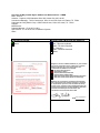
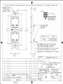
Contractor’s Review:
Architect and CM Review and Approval:
Reviewed for compliance
Notes:
Wrightson, Johnson, Haddon & Williams, Inc. has reviewed
the general conformance of this submission’s technical
design conformity only, and is of the opinion and
recommends the Submission be marked:
No review Action Required
No Exceptions Taken
Rejected, Submit Specified Item
Rejected, Revise and Resubmit
Make Corrections Noted, No Resubmission Required
Make Corrections Noted, Submit Corrected Copy
x
01/07/2013
A – Approved
AN – Approved as Noted
NAR – No Action Required
R – Rejected
R&R – Revise & Resubmit
Notes:
Mark Olsen
Notations do not relieve the contractor from compliance
with requirements of the contract documents. Contractor
is responsible for provision of all information necessary
for this review; confirming and correlating dimensions for
tolerances and clearances; product quantities; fabrication
processes and techniques of construction; and
coordination of this work with other trades.
DATE
01-03-2013
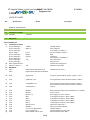
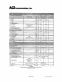
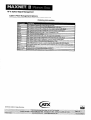
SMATV SYSTEMS
Equipment List
11/16/2012
UMHB
CATV 27 13 43.53
Ref
Manufacturer
Description
Model
Section 27 13 43.53 CATV
2.3 ANTENNA SYSTEM
1.14 CEF/BEF
2.4
Allowance
HEADEND
PART 2 PRODUCTS
2.3 ANTENNA SYSTEM
A
Pixel Technologies
Pixel Technologies
Pixel Technologies
Bonder Tongue
Pixel Technologies
Pixel Technologies
Pixel Technologies
Pixel Technologies
Pixel Technologies
B
Rhon Antenna Products
C
Microwave Filter Co.
2.4 HEADEND
A
Adtec
Adtec
AM/FM Antenna
Inline Amplifier
Power Supply for MBA-12
Extender Amplifier (AMP 3)
RTO
Quadplexer
Power Supply for Quadplexer
Fixed Attenuators
Surge Protector
Antenna Mast and Supports
Band Pass Filter (BPF)
AFHD-4
MBA-12
DA-33
MBS-4
QPLEX
A/R
A/R
Digital Media Hub HD Pro-02-S
Digital Media Hub HD Pro-HD-KEY
HD/SDI Encoder (ENC)
B
Drake
MQM 1000
Frequency Agile Modulator (FAM) - QAM w/ 2-ASI
C
ATX
QMP1000-**GP
Forward Path RF Chassis Mounted Amplifier (AMP1):
D
ATX
ATXQMP200-**L
E
ATX
ATX MPTX8-**
Return Path RF Chassis Mounted Amplifier (AMP2):
Forward Path Optical RF chassis mounted Transmitter
(FOTX)
F
G
H
I
J
K
L
M
N
O
P
Q
ATX
ATX
ATX
ATX
ATX
ATX
ATX
ATX
ATX
ATX
ATX
ATX
MPRX-8
MP3BA
MPAC-110
MP2
MP4
MPT8
MP-16
MP*DC Series
MPMF-3
FLJ1A1A-01 QM99 Series
PCI CD-92002-*R
BWH & BWL 9060 & 9050
Return Path Optical RF chassis mounted Receiver (FORX)
Active Chassis
Power Supply for Active Chassis:
2-WaySplitter/Combiner; (SPL1/CMB1):
4-WaySplitter/Combiner; (SPL2/CMB2)
8-WaySplitter/Combiner; (SPL3/CMB3):
16-Way Splitter/Combiner; (SP•/CMB4):
Directional Coupler (DC)
MCXto F Transition Module
Headend Jumpers
Channel Elimination Filter (CEF)
Band Elimination Filter (BEF)
1 of 4
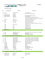
SMATV SYSTEMS
Equipment List
11/16/2012
UMHB
CATV 27 13 43.53
Ref
R
S
T
U
V
W
X
2.5
Manufacturer
Description
Model
Evertz
Evertz
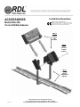
Radio Design Labs
Radio Design Labs
Radio Design Labs
LG
3400DS*-*Series
3400FR
FP-UBC6
ST-MX3
DRA-35S
22LE 5300
Peerless
AVP
ADC
ADC
SA740P
WK-U216E2-Z
R2V-STS
G3V-STS
ADC
ADC
ADC
ADC
ADC
ADC
DISTRIBUTION
BK6V-STS-B
R3
G3B-2
B4B
PPH
FPC
Optical Splitters 1x8
Passive Optical Frame w/supply
Mono Summing Amplifier (SUM)
Din Rail Adapter
Video Monitor/Receiver (MON), 22" LED
Articulating VESA Mount custom mounted to black Middle
Atlantic steel folded edge rack panel
Custom Encoder Patch Panel
Standard Video Patch Cords
Standard Video Patch Cords
Video Patch Cord with patch panel plug connector at one
end and BNC male
Audio Patch cords
Audio Patch cords
Audio Patch cords
Patch Cable Holders
Fiber Patch Cords
ATX
QFN 000A-** GP 2W
ATX
QFRL/DFB1-23
ACI
SST-1-S4CW-01
ACI
SST-4-S4CW-01
SPLITTERS, COMBINERS AND PASSIVE DEVICES
CATV Fiber Node Receiver/Amplifier (CATV NODE):
Return Laser
Drop Amplifier- Single Port
Drop Amplifier- Four Port
H
ATX
ATX
ATX
ATX
ATX
TONER
TONER
TONER
TONER
PANDUIT
PANDUIT
PANDUIT
Bonder Tongue
Two-Way Splitter/Combiner; (SPLA/CMBA)
Three-Way Splitter/Combiner; (SPLB/CMBB)
Four-Way Splitter/Combiner; (SPLc/CMBc)
Eight-Way Splitter/Combiner; (SPLD/CMBD)
Directional Coupler (DC)
Modular Multi-Taps
Equalizer Plate Series
Housing
Housing
Drop Outlet frame
self-terminating F-connector
face plate E/B
Fixed Attenuator (PAD)
2.7
SPLITTERS, COMBINERS AND PASSIVE DEVICES
A
Middle Atlantic
Middle Atlantic
Middle Atlantic
A
B
C
2.6
A
B
C
D
E
F
G
DigiMAX DM2R
DigiMAX DM3
DigiMAX DM4
DigiMAX DM8V
DigiMAX DMDC**Series
TMTX108-**
TMTX-EQ-*
MTX-3H
TMTX-6H
CF1064
CMFSRxx
106 Duples
FAM Series
Equipment Rack
4 fans per cabinet
Fan
WRK-44-32
MW-4FT
Fan 4 ½".
2 of 4
SMATV SYSTEMS
Equipment List
11/16/2012
UMHB
CATV 27 13 43.53
Ref
Manufacturer
Description
Model
Fan Guard
Side Panel
Solid Rear Door
4" riser base
Magnetic Work Light:
Front Rack Mounted Power Strip
horizontal cable management
Misc vent panels
Custom and/or Engraved Panels
Internal Electrical Rack Distribution
Isolated Ground Buss Bar: (800-821-0019)
Tele/Data Distribution Power strip:
B
C
D
E
F
Middle Atlantic
Middle Atlantic
Middle Atlantic
Middle Atlantic
Middle Atlantic
Waber
Middle Atlantic
Middle Atlantic
RCI
Middle Atlantic
APW
Middle Atlantic
2.8
CABLING AND ACCESSORIES
A
CommScope
CommScope
CommScope
CommScope
CommScope
CommScope
CommScope
CommScope
CommScope
Belden
Belden
L-COM
QR 320 JCA
QR 320 JCASS
F59 HEC-2VV
F1160BVR
2287K
F6SSV
F11SSV
2227K (Plenum)
2287K (Plenum)
1694A
1266A
Single Mode Fiber Attenuators
WWD
Belden
1695A
B
C
D
E
F
G
H
I
J
K
L
M
N
Belden
Belden
Belden
AFL Telecommunicatns
Carlon
Panduit
Panduit
SPN-44-312
RIB -*
WL-60
Waber 903CB
HHCM-2
EB series
AVD series
PD-1020J-IG
ICBB78
PD 1220C-NS
YR48788
1815R
1814R
CR0069441001-AIAP
Fiber Pig Tails
FWME2 Series
SAT, AM/FM, and TV Off-Air Antenna Cable
SAT, AM/FM, and TV Off-Air Antenna Cable
Head-end Cable (RG59
Trunk and Feeder Cable (RG11)
Trunk and Feeder Cable (RG11) - Plenum
Drop Cable
Drop Cable
Drop Cable
Drop Cable
Video Cable
Audio Cable
Fiber Attenuators
Broadcast Truck Pedestal
Broadcast Truck Panels
Broadcast Plenum rated Video Cable
flooded & jacketed audio snake cable Audio Cable 6 pair
Broadcast Audio Cable:
Audio Cable 4 pair
Audio Cable 2 pair
Single-Mode Optical Fiber Cable:
Fiber Optic Cable Inner Duct:
Fiber Optic Components
Wall Mount Fiber Optic Interconnect Box (FTB)
FSTHS Series Splice Module Holders & FSTK Series
Splice Trays
O
Panduit
Adapter Panel: Panduit FAP Series APC Adapter Panels
Fiber Optic Rack Mount Enclosure
Provide with Panduit FSTHS Series Splice Module Holders
& FSTK Series
FRME4 Series.
3 of 4
SMATV SYSTEMS
Equipment List
11/16/2012
UMHB
CATV 27 13 43.53
Ref
Manufacturer
Burtek
P
Q
R
S
Liberty Wire
Liberty
Neutrik
Neutrik
Gilbert Engineering
Gilbert Engineering
Description
Model
TBD
Splice Trays.
50 Pair CAT5-Coaches IC JBC/50YD line
CM-RG Series
CM-RG Series
NC3MD-L-1-B
NC3FD-L-1-B
GGB-4U
G-SPB-GLU
Adapter Panel: Panduit FAP Series APC Adapter Panels
F Connector
BNC Connector
XLR-3M
XLR-3F
Ground Block
Ground Block
4 of 4
R3
G3B-2
B4B
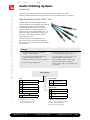
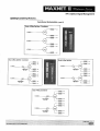
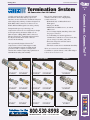
Audio Patching Systems
nÉ£äÊUÊ£än{ÎÊ
À>`V>ÃÌÊ>`ÊÌiÀÌ>iÌÊ*À`ÕVÌÃ
Accessories
Whatever the accessory you need for your audio patchbay, the quality source is ADC.
Products available include patch cords, connectors and jacks, designation strip kits, and more.
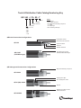
High-Performance Audio Patch Cords
ProPatch audio patch cords are engineered for
flawless performance and durability. Nickel plating
protects plugs against corrosion and ensures
smooth insertion, and the exclusive dielectric
compound between conductors provides low
capacitance for the best signal performance. The
flexible cord drapes neatly without kinking, and
the plug is molded directly onto the cord for
outstanding strain relief.
All ADC patch cords are designed to meet
*È{ÓÊ>`Ê>ÀiÊ>V
i`Ê>vÌiÀÊ`}ÊvÀÊ
perfect concentricity, ensuring consistent, reliable
jack operation.
Features
UÊ iiÌÃÊ`i>`}ÊÈ{£Ê>`Ê*È{ÓÊ
standards for plug compliance
UÊ Standard lengths from .6 m (2 feet) to 1.8 m (6
feet). Other lengths available on request
UÊ *ÀiVÃÊ7
"ÊΣäÊ}vÀ>i®Ê>`ÊL>Ì>Ê
plugs assure proper jack performance
UÊ Colors include red, green, blue, or black. Some
cords also available in yellow or gray
UÊ Quad-star construction for low noise performance
UÊ Ê ÛiÀÃÊ«>ÌV
ÊVÀ`ÃÊvÀÊ,-{ÓÓÊÌÊ,{x°Ê
(Conversion patch cords for longframe to
bantam, single to dual, are also available. Please
contact ADC.)
UÊ Models for analog or digital audio
Catalog Number
__ __ __
Color
Cable Length
R
Red
G
Green
B
Blue
Y
Yellow*
BK
Black
2 .6 m (2')
GY Gray*
Î °ÊÊο®
6
BLANK
B
Digital audio (black only)
* Non-standard colors. Please
contact ADC for these and
other non-standard colors.
ÜÜÜ°>`V°VÊ
Bantam plug
Cable Length
{
DA
Longframe plug
UÊ
£°ÓÊÊ{¿®
6 1.8 m (6')
Dual patch cords are available.
``Ê>ʸӸÊ>vÌiÀÊi}Ì
°ÊÀÊiÝ>«i]Ê
R22 = Red (2') dual longframe
R22B = Red (2') dual bantam
³£xÓÎnnänäÊ
UÊ
£nääÎÈÈÎn£
Ó°Ó{
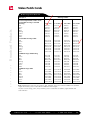
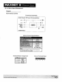
Video Patch Cords
Ordering Information
Description
Ordering Number
3/04
•
1180270
Broadcast Products
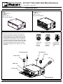
ST Series High-Definition Video Cords
ST Standard Size Plug to Standard
Size Plug
Red
Green
Blue
Black
Orange
Yellow
Violet
White
2 ft./ .61m
R2V-STS
G2V-STS
B2V-STS
BK2V-STS
O2V-STS
Y2V-STS
V2V-STS
W2V-STS
3 ft./.93m
R3V-STS
G3V-STS
B3V-STS
BK3V-STS
O3V-STS
Y3V-STS
V3V-STS
W3V-STS
4 ft./1.22m
R4V-STS
G4V-STS
B4V-STS
BK4V-STS
O4V-STS
Y4V-STS
V4V-STS
W4V-STS
6 ft./1.83m
R6V-STS
G6V-STS
B6V-STS
BK6V-STS
O6V-STS
Y6V-STS
V6V-STS
W6V-STS
ST Standard Size Plug to BNC
Red
Green
Blue
Black
Orange
Yellow
Violet
White
R2V-STS-B
G2V-STS-B
B2V-STS-B
BK2V-STS-B
O2V-STS-B
Y2V-STS-B
V2V-STS-B
W2V-STS-B
R3V-STS-B
G3V-STS-B
B3V-STS-B
BK3V-STS-B
O3V-STS-B
Y3V-STS-B
V3V-STS-B
W3V-STS-B
R4V-STS-B
G4V-STS-B
B4V-STS-B
BK4V-STS-B
O4V-STS-B
Y4V-STS-B
V4V-STS-B
W4V-STS-B
R6V-STS-B
G6V-STS-B
B6V-STS-B
BK6V-STS-B
O6V-STS-B
Y6V-STS-B
V6V-STS-B
W6V-STS-B
ST Midsize Plug to Midsize Plug
Red
Green
Blue
Black
Orange
Yellow
Violet
White
R2V-STM
G2V-STM
B2V-STM
BK2V-STM
O2V-STM
Y2V-STM
V2V-STM
W2V-STM
R3V-STM
G3V-STM
B3V-STM
BK3V-STM
O3V-STM
Y3V-STM
V3V-STM
W3V-STM
R4V-STM
G4V-STM
B4V-STM
BK4V-STM
O4V-STM
Y4V-STM
V4V-STM
W4V-STM
R6V-STM
G6V-STM
B6V-STM
BK6V-STM
O6V-STM
Y6V-STM
V6V-STM
W6V-STM
ST Midsize Plug to BNC
Red
Green
Blue
Black
Orange
Yellow
Violet
White
R2V-STM-B
G2V-STM-B
B2V-STM-B
BK2V-STM-B
O2V-STM-B
Y2V-STM-B
V2V-STM-B
W2V-STM-B
R3V-STM-B
G3V-STM-B
B3V-STM-B
BK3V-STM-B
O3V-STM-B
Y3V-STM-B
V3V-STM-B
W3V-STM-B
R4V-STM-B
G4V-STM-B
B4V-STM-B
BK4V-STM-B
O4V-STM-B
Y4V-STM-B
V4V-STM-B
W4V-STM-B
R6V-STM-B
G6V-STM-B
B6V-STM-B
BK6V-STM-B
O6V-STM-B
Y6V-STM-B
V6V-STM-B
W6V-STM-B
Note: Standard patch cord colors are red, green, blue, and black. These color cords are available in the standard
lengths shown above; please contact ADC for additional custom lengths.
For patch cords in orange, yellow, violet, and white, please contact ADC for leadtime, lengths available and
order minimums.
www.adc.com
•
+1-952-938-8080
•
1-800-726-4266
63
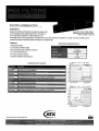
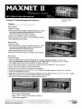
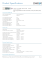
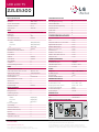
MPEG 2 Standard and
High Definition Encoder
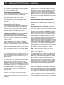
The mediaHUB-Pro 02 is a real-time
Contribution-quality MPEG 2 Standard and High
Definition encoder. It is designed to support the
most demanding Contribution, ATSC, DVB and
IPTV MPEG 2 Distribution applications; the Studio version of the mediaHUB-Pro 02 encodes Cable
Labs VOD and DPI compliant MPEG 2 Transport Streams. The Pro’s auto-detect HD/SD-SDI video
input eliminates the need for user resolution and frame rate configuration. It boasts dual stream
on-board audio encoding of MPEG 1 Layer 2 audio including support for Dolby E and Dolby 5.1
passthrough. Optional dual stream Dolby Digital AC3 encode can be added with a simple software key
either at the factory or in the filed. Standard Adtec transport interfaces include three ASI copper
outputs with included support for transport over GIGE. Audio inputs include AES3 Digital Audio, SDI
and Analog audio. BISS 1 and BISS E encryption is an option that can be field activated with a simple
software key, no hardware required. The Pro’s user interfaces include a comprehensive easy-to-use
front panel interface, on-board Web application
server for configuration and monitoring
plus SNMP 2.0C MIBS. Unique
features of the Studio
features & benefits
TM
MPEG 2 SD Contribution Quality Encoding: Support for MPEG 2
SD 4:2:0 and 4:2:2 Contribution, Distribution and Studio encoding
quality. with mediaHUB-Pro 02 and mediaHUB-Pro 02-S.
MPEG 2 HD Contribution Quality Encoding: Optional upgrade
to MPEG 2 HD 4:2:0 encoding with a simple field upgrade, no
hardware exchange required.
SDI Plug and Encode: Automatic SDI detection (HD and SD) of
standards and frame rates. (HD required HD feature key)
High and Standard Definition Video: One box - both formats.
(HD requires the purchase of MEDIAHUB-PRO-HD-KEY, factory or
field upgrade)
High Performance Audio Encoding and Passthrough: Encode
two stereo pairs of MPEG 1 Layer 2 audio, passthrough Dolby E, or
Dolby Digital 5.1 with optional dual stream Dolby Digital AC3 audio
encoding.
version include a
built-in confidence
decoder with
Easy to Use: Rapidly and accurately configure mediaHUB-HD Pro
via the front panel, on-board web application server or SNMP.
HD/SD-SDI, HDMI
MEDIAHUB-PRO-02-S: Studio version of
encoder adds confidence decoder, RS422
control and 160GB hard drive.
MEDIAHUB-PRO-HD-KEY: Enables gigh
definition MPEG 2 encoding. Software Key.
Field Upgradable.
MEDIAHUB-PRO-DOLBY-KEY: Adds dual
(two-pairs) stereo Dolby Digital AC3
encode. Software Key. Field Upgradable
BISS: BISS 1 and BISS E Encryption
related products
MEDIAHUB-PRO-02: Offers standard
definition MPEG 2 encoding.
DTA-3050:
Digital turn around router for
transporting MPEG 2 via ASI and IP
sources to ASI, SMPTE-310 and IP
outputs
Soloist-HD Pro:
Broadcast quality high definition MPEG
2 and AVC (MPEG 4 Part 10 - H.264)
decoder for broadcast applications
Highest quality MPEG 2 HD and SD: When it comes to the best
on-air look, mediaHUB-HD Pro delivers with excellent quality
Standard and High Definition video encoding. (HD requires
purchase of MEDIAHUB-PRO-HD-KEY, factory or field upgrade)
Monitor: Web Browser, front panel LED and LCD visual alarms,
SNMP traps and event logging are all standard.
mediaHUB-Pro 02-S added Features
Create VOD and DPI-ready Files: Create Cable Labs compliant
Transport streams for use with VOD and DPI.
Control with Accuracy: mediaHUB-HD Pro can control VTR
sources or be controlled by a non linear editor (NLE) via RS-422
for frame accurate mark in/out encoding. (Studio version only)
Hard Drive Capture: Frame accurately capture encodes for VOD
and DPI applications.
Decode While Encode (DWE): Built-in confidence decoder nearly
eliminates the need for external local decoders.
02-2011
options
and D1 outputs.
Adtec Digital US Sales: 615.256.6619 International Sales 904.394.0389 www.adtecinc.com
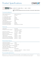
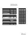
mediaHUB-Pro 02
technical specifications
TM
MPEG 2 Standard and High Definition Encoder
Encoder Video Profiles
Encoder Audio Profiles
Pro-02-S Decoder Specifications
MPEG 2 SD Profile 1: Adaptive Field Frame (AFF) ISO13818-2
Dolby Digital 2.0 (AC3) dual stream encoders option.
Decoder Video Output
MP@ML
MPEG1 Layer 2 dual stream encoders included
- Confidence decode of encode via internal bus, No ASI loop
MPEG 2 SD Profile 2: AFF ISO13818-2 422P@ML
Dolby E, Dolby 5.1 and Dolby Digital 2.0 (AC3) passthrough
required
MPEG 2 HD Profile 2: ISO13818-2 MP@HL (1920 x 1080 or
1280 x 720)
- SD/HDSDI SMPTE 259M (SD) and SMPTE 292M (HD) User
Encoder Audio Input
definable resolution from D1 to 1080i including scaler for Up and
Analog Audio 1 Stereo Balanced (5-Pin Removable Screw Terminal)
Down conversion
Video Encoding Data Rates
Analog Audio 2 Stereo (SAP) Balanced (5-Pin Removable Screw Terminal)
- Composite D1 Video (NTSC/PAL) Not concurrent with HD
MPEG 2 MP@ML SD / 1 Mbs-15 Mbs - NTSC and PAL
AES3-1 digital audio input uncompressed (PCM) or compressed bit stream
- HDMI 1.3 No HDCP
MPEG 2 422P@ML SD / 1 Mbs-50 Mbs - NTSC and PAL
passthrough from external Dolby 2.0, 5.1 or Dolby E encoders (BNC - 75
- DVB-ASI Input
MPEG 2 MP@HL / 7 Mbs-59.5 Mbs
Ohm). Includes compressed bit stream output.
- Decoder Audio Output (Decodes only one pair)
AES3-2 digital audio input uncompressed (PCM) or compressed bit stream
- SDI Embedded audio stereo audio pair SMPTE 272M (SD)
High Definition Video Frame Formats
passthrough from external Dolby 2.0, 5.1 or Dolby E encoders (BNC - 75
SMPTE 299M (HD) User defined PID
720p24, 720p50, 720p60, 1080i50, 1080i60
Ohm). Includes compressed bitstream output.
- HDMI
SDI embedded (4 pairs) with video per SMPTE 272M for SD and SMPTE
- No analog audio output
High Definition Video Encode Resolutions
299M for HD. One user selectable group.
Horizontal Resolutions
User-defined analog and digital level control with sample rate conversion
Decoder Video Profiles
1280, 1920 (1440)
on all inputs
MPEG 2 SD Profile 1: Adaptive Field Frame (AFF) ISO13818-2
Vertical Resolutions
720, 1080
MP@ML
Transport Outputs
MPEG 2 SD Profile 2: AFF ISO13818-2 422P@ML
ISO13818-1 MPEG 2 Transport Stream (188 byte only)
MPEG 2 HD Profile 2: ISO13818-2 MP@HL (1920 x 1080 or
Standard Definition Video Frame Formats
(x3 mirrored outputs)
1280 x 720)
480i, 576i, 480p, 567p
MPEG 2 Transport via GIGE (UDP or RTP)
MPEG 2 Transport to local storage Constant Capture to storage (local or
Decoder Audio Profiles
Standard Definition Video Encode Resolutions
NAS)
Dolby Digital AC-3
Horizontal Resolutions
ASI, IP and Constant Capture operate concurrently
MPEG 1 Layer 2
Vertical Resolutions
Transport User Data
Physical
480, 576
SMPTE 334 VANC data extraction for IEEE 708/608. Concurrent
1 RU chassis (19 x 14 x 1.75)
User defined VANC Line 7-32 data extraction supported
14 pounds
720, 704, 640, 544, 528, 480, 352
Teletext: (NABTS) DVS053 Rev 6
Encoder Filters (SD Only)
Power
Temporal & Spatial (Median)
Conditional Access
Start-up:72 Watts
Time Base Corrector (TBC) on SDI inputs for SD only
BISS 1/E option
Operational: 60 Watts
02-2011
Video Processing
Adtec Digital US Sales: 615.256.6619 International Sales 904.394.0389 www.adtecinc.com
mediaHUB-Pro 02
Chroma filtering and scaling for NTSC/PAL
Table Compliance
User Interface Requirements
Encoder Video Input
MPEG Program Specific Information (PSI) Table Compliance:
Supported Browsers
Standard Definition (SD) Video Inputs (Encoder)
PAT
- IE 7 and higher
Analog NTSC and PAL Composite (BNC)
PMT
- Firefox 3.0.0 and higher
SDI (SMPTE 259M) with embedded audio (SMPTE 272M)
DVB Service Information (SI) Table Compliance (Static)
- Safari 3.0.0 and higher
Auto detect SD 270Mbps for SD
SDT
- Opera 9.0 and higher
D1 Encoding Only - no internal up-conversion.
NIT
TDT/TOT
High Definition (HD) Video Inputs (Encoder)
SCTE 35 Splice Point injection
HD-SDI input video, (SMPTE 292M) with embedded audio
ATSC A65B (PSIP) Table compliance (Static)
(SMPTE 299M)
MGT (TVCT, STT, RRT, EIT)
Specifications subject to change without written notice.
Auto detect HD 1.485 Gbs.
- For dynamic DVB-SI use Adtec's DTA-3050 and DTVGuide web hosted EIT
* SDI and HD-SDI are the same connector with auto
SI Server.
standard (resolution and frame rate) detection.
- For dynamic A65B PSIP use Adtec's DTA-3051 and DTVGuide web service
©2011 Adtec Digital. mediaHUB-Pro 02 is a trademark of Adtec Digital. Other product and company names may be trademarks or registered trademarks of their respective companies. This information may not, in whole or in part, be copied, photocopied, reproduced and translated,
or reduced to any electronic medium or machine-readable form without prior consent in writing from Adtec Digital.
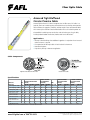
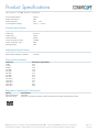
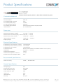
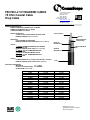
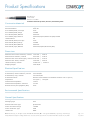
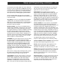
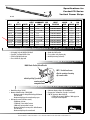
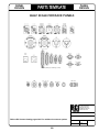
Fiber Optic Cable
Armored Tight Buffered
Circular Premise Cable
Armored Tight Buffered CPC Cables incorporate 4 to 144 fiber count CPC cables in a
jacketed, aluminum interlocking armor. Jacketed aluminum interlocking armor provides
the best balance of ruggedness, flexibility, and low weight. Flame rated armored cables
with no outer jacket and flame rated armored cables with steel interlocking armor are
also available. Interlocking armor can also be used with other types of trunk cables,
including Indoor/Outdoor Distribution, Breakout and Premise MicroCore®.
Applications
• Routing inside of buildings where additional ruggedness is required or where increased
rodent resistance is required
• Extra protection for fiber optic cables in harsh industrial environments
• Manufacturing plants
• High-density routings in data center application
Cable Components
High Fiber Count Circular Premise Cable
Circular Premise Cable
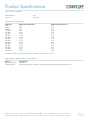
Specifications
Core Size/
Fiber Type
(6) 62.5 Giga-Link™ 300
(8) 62.5 Giga-Link™ 1000
(5) 50 Giga-Link™ 600
(7) 50 Giga-Link™ 2000
(A) 50 Laser-Link 150
(L) 50 Laser-Link 300
(C) 50 Laser-Link 550
(K) SM Futureguide
SR-15e Bend Insensitive
(9) SM
(1) 100/140 Multimode
ISO/
IEC
OM1
OM1
OM2
OM2
OM2
OM3
OM4
OS2
OS2
Maximum Attenuation
(dB/km)
850 nm 1300 nm 1550 nm
3.5
1.2
N/A
3.5
1.2
N/A
3.5
1.5
N/A
3.5
1.2
N/A
3.0
1.2
N/A
3.0
1.2
N/A
3.0
1.2
N/A
N/A
0.5
0.5
Overfill Launch
Min. Bandwidth
(MHz•km)
850 nm 1300 nm
200
600
350
600
500
500
500
800
700
500
1500
500
3500
550
N/A
N/A
Gigabit Ethernet
Min. Link Distance
(meters)
EMBc
(MHz•km) 850 nm
1300 nm
N/A
300
550
N/A
500
1000
N/A
600
600
N/A
750
2000
950
800
550
2000
1000
550
4700
1040
550
N/A
N/A
5000
10 Gigabit Ethernet
Min. Link Distance
(meters)
850 nm
1300 nm
32
—
65
—
82
—
110
—
150
—
300
—
550
—
N/A
10,000
N/A
5.5
N/A
100
N/A
N/A
N/A
N/A
0.5
3.5
0.5
N/A
N/A
100
N/A
N/A
5,000
N/A
10,000
N/A
Tested to meet or exceed EIA/TIA 568-B3 / Telcordia GR-409-CORE
www.AFLglobal.com or (800) 235-3423
© 2002-2011, AFL, all rights reserved. Revision 3.1, 9.27.11
Specifications are subject to change without notice.
16
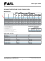
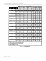
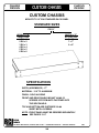
Fiber Optic Cable
Armored Tight Buffered Circular Premise Cable
Mechanical Data
NOMINAL
DIAMETER
AFL No.
RISER
PLENUM
Fiber
Count
INCHES
(MM)
Riser
WEIGHT
PLENUM
LBS/1000 FT LBS/1000 FT
(KG/KM)
(KG/KM)
TENSION
Riser
BENDING RADIUS
PLENUM
Installation
Long
Term
Installation
Long
Term
LBS (N)
LBS (N)
LBS (N)
LBS (N)
INCHES (CM)
INCHES
(CM)
Installation Long Term
UR004481001-AIAR
UP004*481001-AIAP
4
0.46 (11.8)
79 (117)
89 (132)
150 (660)
45 (198)
100 (440)
30 (132)
7.0 (17.7)
5.0 (12.7)
CR006441001-AIAR
CP006*441001-AIAP
6
0.46 (11.8)
74 (109)
82 (122)
150 (660)
45 (198)
100 (440)
30 (132)
7.0 (17.7)
4.8 (12.2)
CR012551001-AIAR
CR024891001-AIAR
CP012*551001-AIAP
CP024*841001-AIAP
12
24
0.46 (11.8)
0.62 (15.7)
79 (117)
129 (193)
89 (132)
144 (215)
150 (660)
300 (1320)
45 (198)
90 (396)
100 (440)
150 (660)
30 (132)
45 (198)
7.0 (17.7)
9.3 (23.6)
5.0 (12.7)
5.3 (13.4)
CR024441001-AIAR
CP024*441001-AIAP
24
0.52 (13.3)
247 (367)
273 (407)
300 (1320)
90 (396)
150 (660)
45 (198)
7.9 (20.0)
5.2 (13.3)
CR036551001-AIAR
CR048551001-AIAR
CR072551001-AIAR
CR096551001-AIAR
CR144551001-AIAR
CP036*551001-AIAP
CP048*551001-AIAP
CP072*551001-AIAP
CP096*551001-AIAP
CP144*551001-AIAP
36
48
72
96
144
0.94 (24)
0.94 (24)
1.10 (27.9)
1.21 (30.7)
1.32 (33.5)
256 (395)
256 (395)
355 (530)
472 (705)
498 (742)
294 (439)
294 (439)
401 (597)
507 (755)
534 (796)
300 (1320)
300 (1320)
300 (1320)
300 (1320)
300 (1320)
90 (396)
90 (396)
90 (396)
90 (396)
90 (396)
150 (660)
150 (660)
150 (660)
150 (660)
150 (660)
45 (198)
45 (198)
45 (198)
45 (198)
45 (198)
14.2 (36.0)
14.2 (36.0)
16.5 (41.9)
18.1 (46.1)
19.8 (50.3)
9.4 (24.0)
9.4 (24.0)
11.0 (27.9)
12.1 (30.7)
13.2 (33.5)
Please specify fiber type when ordering (see below)
5 = 50/125 µm multimode GIGA-Link™ 600
7 = 50/125 µm multimode GIGA-Link™ 2000
6 = 62.5/125 µm multimode GIGA-Link™ 300
8 = 62.5/125 µm multimode GIGA-Link™ 1000
9 = 9/125 µm single-mode
L = 50/125 µm multimode Laser-Link 300 for 10 Gigabit Ethernet
K = Single-mode Futureguide SR-15e Bend Insensitive
Temperature Specifications
Temperature Range
TYpe
Contact Customer Service for special fiber types/performance needs.
OPERATING/
INSTALLATION
STORAGE
Plenum
0°C to +70°C
-40°C to +75°C
Riser
-10°C to +70°
-40°C to +75°
Cable Length - Reel Size
ITEM
Reel Height (inches)
Reel Outside Width (inches)
Drum Diameter (inches)
Reel Weight (lbs)
CAPACITY: meters (feet)
4 Fiber w/Interlocking Armor
6 Fiber w/Interlocking Armor
8 Fiber w/Interlocking Armor
12 Fiber w/Interlocking Armor
18 Fiber w/Interlocking Armor
24 Fiber w/Interlocking Armor
REEL F
42
36
23
148
REEL G
60
36
30
287
2,600 (8,530)
2,600 (8,530)
2,600 (8,530)
2,250 (7,382)
1,700 (5,577)
1,500 (4,921)
5,000 (16,404)
5,000 (16,404)
5,000 (16,404)
4,800 (15,748)
3,600 (11,811)
3,200 (10,500)
www.AFLglobal.com or (800) 235-3423
© 2002-2011, AFL, all rights reserved. Revision 3.1, 9.27.11
Specifications are subject to change without notice.
17
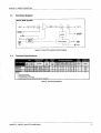
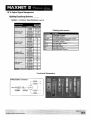
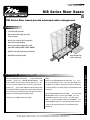
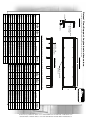
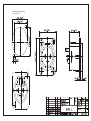
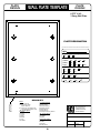
MODEL
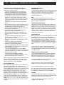
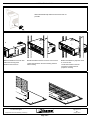
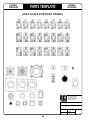
UNIVERSAL PANEL SYSTEM
UNIVERSAL BULKHEAD PANEL SYSTEM
• Design your own bulkhead
• Extensive selection of connector modules
• 1RU, 2RU & 3RU, 16 & 12 position available
• Strain relief cable bar is standard
Model WK-U216E2-Z
with optional Connector Kits
Model WK-U116E1-Z
2RU version shown above
Model WK-U212E2-Z
2 RU
Side View
Model WK-U112E1-Z
6.00” [15.24]
1 RU
Full List of Universal Connector Kits on the Rear
www.amt.com
Insulated Bulkhead
Modular Bulkhead
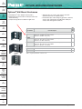
Universal Connector Kits
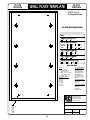
Ordering Information
Model
Description
Universal Panel - Panel with Cable Bar Only; no Connectors, no Adaptor Plates, no Cover Plates
3RU, 2x16 Universal Panel, Panel & Cable Bar Only, No Connectors
WK-U216E3-Z
2RU, 2x16 Universal Panel, Panel & Cable Bar Only, No Connectors
WK-U216E2-Z
1RU, 1x16 Universal Panel, Panel & Cable Bar Only, No Connectors
WK-U116E1-Z
3RU, 2x12 Universal Panel, Panel & Cable Bar Only, No Connectors
WK-U212E3-Z
2RU, 2x12 Universal Panel, Panel & Cable Bar Only, No Connectors
WK-U212E2-Z
1RU, 1x12 Universal Panel, Panel & Cable Bar Only, No Connectors
WK-U112E1-Z
3 RU Assembly of connectors to panel
BUILD3
2 RU Assembly of connectors to panel
BUILD2
1 RU Assembly of connectors to panel
BUILD1
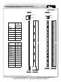
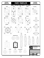
Ordering Information
Model
Description
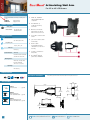
Connector Kits, kits include all components necessary to mount connector to panel
Audio
UE3R-C
UE3R-S
UMIDI
UNL2MP
UNL4MP
UNL4MP-B
UNX331
UNY331
UNX330
UNY330
UNX430
UNY430
UNX530
UNY530
UNX630
UNX631-S
UNY630
UNX730
UNY730
URCA-R
URCA-W
URCA-Y
US35J
USPJ
EDAC Receptacle, 3 pin crimp, adaptor plate(s), hardware
EDAC Receptacle, 3 pin solder, adaptor plate(s), hardware
MIDI Isolated Connector, solder type, hardware
Speakon Connector, 2-Pole, solder termination, panel mount, hardware
Speakon Connector, 4-Pole, solder termination, panel mount, hardware
Speakon Connector, 4-Pole, black/gold contacts, solder, panel mount, h/w
XLR, female, 3 pin, silver, solder termination, panel mount, hardware
XLR, male, 3 pin, silver, solder termination, panel mount, hardware
XLR female, 3 pin, black/gold contacts, solder, panel mount, hardware
XLR male, 3 pin, black/gold contacts, solder, panel mount, hardware
XLR female, 4 pin, black/gold contacts, solder, panel mount, hardware
XLR male, 4 pin, black/gold contacts, solder, panel mount, hardware
XLR female, 5 pin, black/gold contacts, solder, panel mount, hardware
XLR male, 5 pin, black/gold contacts, solder, panel mount, hardware
XLR female, 6 pin, black/gold contacts, solder, panel mount, hardware
XLR female, 6 pin, silver, solder, Switchcraft equivalent, panel mount, h/w
XLR male, 6 pin, black/gold contacts, solder, panel mount, hardware
XLR female, 7 pin, black/gold contacts, solder, panel mount, hardware
XLR male, 7 pin, black/gold contacts, solder, panel mount, hardware
RCA Feedthru, red, adaptor plate(s), hardware
RCA Feedthru, white, adaptor plate(s), hardware
RCA Feedthru, yellow, adaptor plate(s), hardware
Stereo Mini-Audio Jack 3.5mm, female, solder, adaptor plate(s), hardware
1/4” Stereo Phone Jack, solder termination, panel mount, hardware
Video
UDVI-IS
UHF310
UFJ310R
UJJ300
UJJ300R
UBNC50-F
USMA
USVHS-4G
USVHS-4N
DVI-I Single Link Feedthru, F-F, adaptor plate(s), hardware (req 2 positions)
F Style Feedthru, AVP HF310, adaptor plate(s), hardware
F Style Feedthru, recessed, AVP HF310, adaptor plate(s), hardware
BNC Coaxial Feedthru, 3 GHz, AVP JJ300, adaptor plate(s), hardware
BNC Coaxial Feedthru, 3 GHz, recessed, AVP JJ300, adaptor plate(s), h/w
BNC Coaxial Feedthru, 50 Ohm, F-F, adapter plate(s), hardware
SMA 50 Ohm Coaxial Connector, feed-thru, f-f, adaptor plate(s), hardware
SVHS Feedthru, 4 pin, gold contacts, adaptor plate(s), hardware
SVHS Feedthru, 4 pin, nickel contacts, adaptor plate(s), hardware
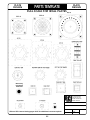
Ordering Information
Model
Description
Connector Kits, kits include all components necessary to mount connector to panel
Data, Network
UDB9-CF
UDB9-CM
UDB9-SF
UDB9-SM
UDB9-SCF
UDB9-SCM
UFW-4
UFW-6
UHD15-CF
UHD15-CM
UHDMI-DFF
UMD66FF
URJ11-F
URJ11
URJ45-F
URJ45-5E
URJ45-6
URJ45-6A
URJ45-6AS
URJ45-6F
USB-A
USB-B
USB-AB
DB9 Female, crimp pin contacts, adaptor plate(s), hardware
DB9 Male, crimp pin contacts, adaptor plate(s), hardware
DB9 Female, solder pin contacts, adaptor plate(s), hardware
DB9 Male, solder pin contacts, adaptor plate(s), hardware
DB9 Female, solder cup pin contacts, adaptor plate(s), hardware
DB9 Male, solder cup pin contacts, adaptor plate(s), hardware
FireWire, 4 pin, IEEE 1394, Feedthru, female-female, adaptor plate(s), hardware
FireWire, 6 pin, IEEE 1394, Feedthru, female-female, chassis mount, hardware
HD15/VGA 15 pin connector, female, crimp, adaptor plate(s), hardware
HD15/VGA 15 pin connector, male, crimp, adaptor plate(s), hardware
HDMI feedthru, female-female, chassis mount, hardware
Mini Din Feedthru, 6 pin female-female, PS/2, keyboard, adaptor plate(s), hardware
RJ11 6 pos/6 con, Feedthru, female-female, adaptor plate(s), hardware
RJ11 6 pos/6 con, IDC interface, adaptor plate(s), hardware (tool-less termination)
RJ45 CAT5E, Feedthru, female-female, adaptor plate(s), hardware
RJ45 CAT5E, 110 interface, no door, adaptor plate(s), hardware (req. 110 punch tool)
RJ45 CAT6, 110 interface, no door, adaptor plate(s), hardware (tool-less termination)
RJ45 CAT6A, 110 interface, no door, adaptor plate(s), hardware (req. 110 punch tool)
RJ45 CAT6A, EMI/RFI Shielding, die-cast housing, adaptor plate(s), h/w (tool-less term.)
RJ45 CAT6, Feedthru, female-female, adaptor plate(s), hardware
USB Type A Feedthru, female-female, adaptor plate(s), hardware
USB Type B Feedthru, female-female, adaptor plate(s), hardware
USB Type A front, Type B on rear, female-female, adaptor plate(s), hardware
Fiber Optic
UFO-ST
ULCD-T
ULCD-MM
USC-0
USC-1
UTOS
ST fiber optic coupler, feed-thru, female-female, adaptor plate(s), hardware
LC Duplex Adaptor suitable for singlemode & multimode applications, adaptor plate(s), h/w
LC Duplex Adaptor for Multimode applications, adaptor plate(s), hardware
SC Multimode fiber optic connector, feed-thru, female-female, adaptor plate(s), hardware
SC Singlemode/Multimode fiber optic connector, feed-thru, f-f, adaptor plate(s), hardware
Toslink optical audio coupler, feed-thru, adaptor plate(s), hardware
Miscellaneous
UCP
UB2-M
UB3-M
UBP1-S
UBP2-S
UTNC-F
UMTS-L
Blank Cover Plate, black, hardware, covers one position
Banana Jacks, 2, red/black, solder, adaptor plate(s), hardware
Banana Jacks, 3, red/black/green, solder, adaptor plate(s), hardware
Binding Post, single, green, solder, will accept banana jacks, adaptor plate(s), h/w
Binding Posts, double, red/black, solder, will accept banana jacks, adaptor plate(s), h/w
TNC Coaxial Adapter, Feedthru, F-F, 50 Ohm, adaptor plate(s), hardware
Miniature Toggle Switch, DPDT, Locking Handle, 3 Amps, 250VAC, Solder, adaptor plate(s), h/w
In the interest of improved design and performance, AVP reserves the right to make changes in its specifications without prior notice. Copyright © 2007 AVP MFG & Supply Inc.
www.amt.com
Advanced Media Technologies, Inc. ∙ 3150 SW 15th Street Deerfield Beach, FL 33442
(888) 293-5856 ∙ (954) 427-5711 ∙ Fax (954) 427-9688
Detailed Specifications & Technical Data
METRIC MEASUREMENT VERSION
1266A Multi-Conductor - Single-Pair Cable
For more Information
please call
1-800-Belden1
Description:
22 AWG stranded (7x30) TC conductors, polypropylene insulation, twisted pair, overall Beldfoil shield
(100% coverage), 24 AWG stranded TC drain wire, PVC jacket.
Physical Characteristics (Overall)
Conductor
AWG:
# Pairs AWG Stranding Conductor Material
1
22
7x30
TC - Tinned Copper
Insulation
Insulation Material:
Insulation Material Wall Thickness (mm)
PP - Polypropylene 0.254
Outer Shield
Outer Shield Material:
Outer Shield Trade Name Type Outer Shield Material
Beldfoil®
Coverage (%)
Tape Aluminum Foil-Polyester Tape 100
Outer Shield Drain Wire AWG:
AWG Stranding Drain Wire Conductor Material
24
7x32
TC - Tinned Copper
Outer Jacket
Outer Jacket Material:
Outer Jacket Material
Nom. Wall Thickness (mm)
PVC - Polyvinyl Chloride 0.508
Overall Cable
Overall Nominal Diameter:
3.632 mm
Pair
Pair Color Code Chart:
Number Color
1
Black & Red
Pair Lay Length & Direction:
Lay Length (mm) Twists/ft. (twist/m)
44.449825
22.508
Mechanical Characteristics (Overall)
Operating Temperature Range:
-20°C To +60°C
UL Temperature Rating:
60°C
Bulk Cable Weight:
20.835 Kg/Km
Max. Recommended Pulling Tension:
111.205 N
Min. Bend Radius (Install)/Minor Axis:
38.100 mm
Page 1 of 3
02-01-2012
Detailed Specifications & Technical Data
METRIC MEASUREMENT VERSION
1266A Multi-Conductor - Single-Pair Cable
Applicable Specifications and Agency Compliance (Overall)
Applicable Standards & Environmental Programs
NEC/(UL) Specification:
CM
CEC/C(UL) Specification:
CM
EU CE Mark:
Yes
EU Directive 2000/53/EC (ELV):
Yes
EU Directive 2002/95/EC (RoHS):
Yes
EU RoHS Compliance Date (mm/dd/yyyy):
01/01/2004
EU Directive 2002/96/EC (WEEE):
Yes
EU Directive 2003/11/EC (BFR):
Yes
CA Prop 65 (CJ for Wire & Cable):
Yes
MII Order #39 (China RoHS):
Yes
Flame Test
UL Flame Test:
UL1685 UL Loading
Plenum/Non-Plenum
Plenum (Y/N):
No
Electrical Characteristics (Overall)
Nom. Characteristic Impedance:
Impedance (Ohm)
55
Nom. Inductance:
Inductance (µH/m)
0.59058
Nom. Capacitance Conductor to Conductor:
Capacitance (pF/m)
98.43
Nom. Capacitance Cond. to Other Conductor & Shield:
Capacitance (pF/m)
177.174
Nominal Velocity of Propagation:
VP (%)
66
Nominal Delay:
Delay (ns/m)
4.9215
Nom. Conductor DC Resistance:
DCR @ 20°C (Ohm/km)
49.215
Nominal Outer Shield DC Resistance:
DCR @ 20°C (Ohm/km)
59.058
Max. Operating Voltage - UL:
Voltage
300 V RMS
Max. Recommended Current:
Current
2.3 Amps per conductor @ 25°C
Page 2 of 3
02-01-2012
Detailed Specifications & Technical Data
METRIC MEASUREMENT VERSION
1266A Multi-Conductor - Single-Pair Cable
Notes (Overall)
Notes: Unique design features lower capacitance and greater flexibility than standard audio pair constructions.
Related Documents:
No related documents are available for this product
Put Ups and Colors:
Item #
Putup
Ship Weight
Color
1266A 001U1000
305 MT
6.804 KG
BROWN
Notes
Item Desc
2 #22 PP FS PVC
1266A 002U1000
305 MT
6.804 KG
RED
2 #22 PP FS PVC
1266A 003U1000
305 MT
6.804 KG
ORANGE
2 #22 PP FS PVC
1266A 004U1000
305 MT
6.804 KG
YELLOW
2 #22 PP FS PVC
1266A 005U1000
305 MT
6.804 KG
GREEN, DARK
2 #22 PP FS PVC
1266A 006U1000
305 MT
6.804 KG
BLUE, LIGHT
2 #22 PP FS PVC
1266A 007U1000
305 MT
6.804 KG
VIOLET
2 #22 PP FS PVC
1266A 008U1000
305 MT
6.804 KG
GRAY
2 #22 PP FS PVC
1266A 009U1000
305 MT
6.804 KG
WHITE
2 #22 PP FS PVC
1266A 010U1000
305 MT
6.804 KG
BLACK
1266A 0101000
305 MT
6.804 KG
BLACK
2 #22 PP FS PVC
C
2 #22 PP FS PVC
Notes:
C = CRATE REEL PUT-UP.
Revision Number: 1
Revision Date: 04-18-2008
© 2012 Belden, Inc
All Rights Reserved.
Although Belden makes every reasonable effort to ensure their accuracy at the time of this publication, information and specifications
described herein are subject to error or omission and to change without notice, and the listing of such information and specifications does not
ensure product availability.
Belden provides the information and specifications herein on an "AS IS" basis, with no representations or warranties, whether express,
statutory or implied. In no event will Belden be liable for any damages (including consequential, indirect, incidental, special, punitive, or
exemplary damages) whatsoever, even if Belden has been advised of the possibility of such damages, whether in an action under contract,
negligence or any other theory, arising out of or in connection with the use, or inability to use, the information or specifications described herein.
All sales of Belden products are subject to Belden's standard terms and conditions of sale.
Belden believes this product to be in compliance with EU RoHS (Directive 2002/95/EC, 27-Jan-2003). Material manufactured prior to the
compliance date may be in stock at Belden facilities and in our Distributor’s inventory. The information provided in this Product Disclosure, and
the identification of materials listed as reportable or restricted within the Product Disclosure, is correct to the best of Belden’s knowledge,
information, and belief at the date of its publication. The information provided in this Product Disclosure is designed only as a general guide
for the safe handling, storage, and any other operation of the product itself or the one that it becomes a part of. This Product Disclosure is not
to be considered a warranty or quality specification. Regulatory information is for guidance purposes only. Product users are responsible for
determining the applicability of legislation and regulations based on their individual usage of the product.
Belden declares this product to be in compliance with EU LVD (Low Voltage Directive 73/23/EEC), as amended by directive 93/68/EEC.
Page 3 of 3
02-01-2012
Detailed Specifications & Technical Data
ENGLISH MEASUREMENT VERSION
1694A Coax - Low Loss Serial Digital Coax
For more Information
please call
1-800-Belden1
Description:
RG-6/U Type, 18 AWG solid .040" bare copper conductor, gas-injected foam HDPE insulation, Duofoil® +
tinned copper braid shield (95% coverage), PVC jacket.
Physical Characteristics (Overall)
Conductor
AWG:
# Coax AWG Stranding Conductor Material Dia. (in.)
1
18
Solid
BC - Bare Copper
.040
Insulation
Insulation Material:
Insulation Material
Dia. (in.)
Gas-injected FHDPE - Foam High Density Polyethylene .180
Outer Shield
Outer Shield Material:
Layer # Outer Shield Trade Name Type Outer Shield Material
1
Duofoil®
2
Coverage (%)
Tape Aluminum Foil-Polyester Tape-Aluminum Foil 100
Braid TC - Tinned Copper
95
Outer Jacket
Outer Jacket Material:
Outer Jacket Material
PVC - Polyvinyl Chloride
Overall Cable
Overall Nominal Diameter:
0.274 in.
Mechanical Characteristics (Overall)
Operating Temperature Range:
-30°C To +75°C
UL Temperature Rating:
75°C
Bulk Cable Weight:
41 lbs/1000 ft.
Max. Recommended Pulling Tension:
69 lbs.
Min. Bend Radius (Install)/Minor Axis:
2.750 in.
Applicable Specifications and Agency Compliance (Overall)
Applicable Standards & Environmental Programs
NEC/(UL) Specification:
CMR
CEC/C(UL) Specification:
CMG
EU CE Mark:
Yes
EU Directive 2000/53/EC (ELV):
Yes
EU Directive 2002/95/EC (RoHS):
Yes
EU RoHS Compliance Date (mm/dd/yyyy):
01/01/2004
EU Directive 2002/96/EC (WEEE):
Yes
Page 1 of 4
02-01-2012
Detailed Specifications & Technical Data
ENGLISH MEASUREMENT VERSION
1694A Coax - Low Loss Serial Digital Coax
EU Directive 2003/11/EC (BFR):
Yes
CA Prop 65 (CJ for Wire & Cable):
Yes
MII Order #39 (China RoHS):
Yes
RG Type:
6/U
Flame Test
UL Flame Test:
UL1666 Vertical Shaft
Suitability
Suitability - Indoor:
Yes
Suitability - Outdoor:
Yes - Black only
Suitability - Aerial:
Yes - Black only, when supported by a messenger wire
Plenum/Non-Plenum
Plenum (Y/N):
No
Plenum Number:
1695A
Electrical Characteristics (Overall)
Nom. Characteristic Impedance:
Impedance (Ohm)
75
Nom. Inductance:
Inductance (µH/ft)
0.106
Nom. Capacitance Conductor to Shield:
Capacitance (pF/ft)
16.2
Nominal Velocity of Propagation:
VP (%)
82
Nominal Delay:
Delay (ns/ft)
1.24
Nom. Conductor DC Resistance:
DCR @ 20°C (Ohm/1000 ft)
6.4
Nominal Outer Shield DC Resistance:
DCR @ 20°C (Ohm/1000 ft)
2.8
Nom. Attenuation:
Freq. (MHz) Attenuation (dB/100 ft.)
1.000
0.240
3.580
0.440
5.000
0.520
6.000
0.570
7.000
0.610
10.000
0.710
12.000
0.780
25.000
1.080
67.500
1.650
71.500
1.690
88.500
1.860
100.000
1.950
135.000
2.240
143.000
2.300
Page 2 of 4
02-01-2012
Detailed Specifications & Technical Data
ENGLISH MEASUREMENT VERSION
1694A Coax - Low Loss Serial Digital Coax
180.000
2.570
270.000
3.170
360.000
3.690
540.000
4.600
720.000
5.380
750.000
5.500
1000.000
6.420
1500.000
7.990
2000.000
9.370
2250.000
10.010
3000.000
11.780
4500.000
14.920
Max. Operating Voltage - UL:
Voltage
300 V RMS
Other Electrical Characteristic 1:
Impedance tested in accordance with ASTM D-4566 paragraph 43.2, option 2
using a 75 Ohm fixed bridge and termination. 75 +/- 1.5 Ohms
Other Electrical Characteristic 2:
Return Loss tested in accordance with ASTM D-4566 paragraph 45.3, using a
75 Ohm fixed bridge and termination.
Minimum Return Loss:
Start Freq. (MHz) Stop Freq. (MHz) Min. RL (dB)
5
1600
23
1600
4500
21
Sweep Test
Sweep Testing:
100% Sweep tested 5 MHz to 4.5 GHz.
Misc. Information (Overall)
Notes (Overall)
Notes: Also available in bundled versions. See 7710A through 7713A.
Related Documents:
No related documents are available for this product
Put Ups and Colors:
Item #
Putup
Ship Weight
Color
Notes
Item Desc
1694A N3U1000
1,000 FT
45.000 LB
GREEN, MIL
C
#18 PE/GIFHDPE SH FR PVC
1694A N3U5000
5,000 FT
225.000 LB
GREEN, MIL
CN
#18 PE/GIFHDPE SH FR PVC
1694A 0011000
1,000 FT
45.000 LB
BROWN
C
#18 PE/GIFHDPE SH FR PVC
1694A 0015000
5,000 FT
225.000 LB
BROWN
CN
#18 PE/GIFHDPE SH FR PVC
1694A 0021000
1,000 FT
45.000 LB
RED
C
#18 PE/GIFHDPE SH FR PVC
1694A 0025000
5,000 FT
225.000 LB
RED
CN
#18 PE/GIFHDPE SH FR PVC
1694A 003CUT
1 FT
0.046 LB
ORANGE
1694A 0031000
1,000 FT
45.000 LB
ORANGE
C
#18 PE/GIFHDPE SH FR PVC
1694A 0041000
1,000 FT
45.000 LB
YELLOW
C
#18 PE/GIFHDPE SH FR PVC
1694A 0061000
1,000 FT
45.000 LB
BLUE, LIGHT
C
#18 PE/GIFHDPE SH FR PVC
1694A 0065000
5,000 FT
225.000 LB
BLUE, LIGHT
CN
#18 PE/GIFHDPE SH FR PVC
1694A 007CUT
1 FT
0.046 LB
VIOLET
1694A 0071000
1,000 FT
45.000 LB
VIOLET
C
#18 PE/GIFHDPE SH FR PVC
1694A 0075000
5,000 FT
225.000 LB
VIOLET
CN
#18 PE/GIFHDPE SH FR PVC
1694A 0081000
1,000 FT
45.000 LB
GRAY
C
#18 PE/GIFHDPE SH FR PVC
1694A 0085000
5,000 FT
225.000 LB
GRAY
CN
#18 PE/GIFHDPE SH FR PVC
1694A 0091000
1,000 FT
45.000 LB
WHITE
C
#18 PE/GIFHDPE SH FR PVC
1694A 0101000
1,000 FT
45.000 LB
BLACK
C
#18 PE/GIFHDPE SH FR PVC
1694A 010500
500 FT
22.500 LB
BLACK
C
#18 PE/GIFHDPE SH FR PVC
1694A 0105000
5,000 FT
225.000 LB
BLACK
CN
#18 PE/GIFHDPE SH FR PVC
#18 PE/GIFHDPE SH FR PVC
#18 PE/GIFHDPE SH FR PVC
Notes:
Page 3 of 4
02-01-2012
Detailed Specifications & Technical Data
ENGLISH MEASUREMENT VERSION
1694A Coax - Low Loss Serial Digital Coax
C = CRATE REEL PUT-UP.
N = FINAL PUT-UP LENGTH MAY VARY -0% TO +10% FROM LENGTH SHOWN.
Revision Number: 13
Revision Date: 02-22-2010
© 2012 Belden, Inc
All Rights Reserved.
Although Belden makes every reasonable effort to ensure their accuracy at the time of this publication, information and specifications
described herein are subject to error or omission and to change without notice, and the listing of such information and specifications does not
ensure product availability.
Belden provides the information and specifications herein on an "AS IS" basis, with no representations or warranties, whether express,
statutory or implied. In no event will Belden be liable for any damages (including consequential, indirect, incidental, special, punitive, or
exemplary damages) whatsoever, even if Belden has been advised of the possibility of such damages, whether in an action under contract,
negligence or any other theory, arising out of or in connection with the use, or inability to use, the information or specifications described herein.
All sales of Belden products are subject to Belden's standard terms and conditions of sale.
Belden believes this product to be in compliance with EU RoHS (Directive 2002/95/EC, 27-Jan-2003). Material manufactured prior to the
compliance date may be in stock at Belden facilities and in our Distributor’s inventory. The information provided in this Product Disclosure, and
the identification of materials listed as reportable or restricted within the Product Disclosure, is correct to the best of Belden’s knowledge,
information, and belief at the date of its publication. The information provided in this Product Disclosure is designed only as a general guide
for the safe handling, storage, and any other operation of the product itself or the one that it becomes a part of. This Product Disclosure is not
to be considered a warranty or quality specification. Regulatory information is for guidance purposes only. Product users are responsible for
determining the applicability of legislation and regulations based on their individual usage of the product.
Belden declares this product to be in compliance with EU LVD (Low Voltage Directive 73/23/EEC), as amended by directive 93/68/EEC.
Page 4 of 4
02-01-2012
Detailed Specifications & Technical Data
ENGLISH MEASUREMENT VERSION
1695A Coax - Low Loss Serial Digital Coax
For more Information
please call
1-800-Belden1
Description:
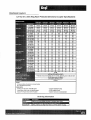
RG-6/U type, 18 AWG solid .040" bare copper conductor, plenum, foam FEP insulation, Duofoil® + tinned
copper braid shield (95% coverage), Flamarrest® jacket.
Physical Characteristics (Overall)
Conductor
AWG:
# Coax AWG Stranding Conductor Material Dia. (in.)
1
18
Solid
BC - Bare Copper
.040
Insulation
Insulation Material:
Insulation Trade Name Insulation Material
Teflon®
Dia. (in.)
FFEP - Foam Fluorinated Ethylene Propylene .170
Outer Shield
Outer Shield Material:
Layer # Outer Shield Trade Name Type Outer Shield Material
1
Duofoil®
Coverage (%)
Tape Aluminum Foil-Polyester Tape-Aluminum Foil 100
2
Braid TC - Tinned Copper
95
Outer Jacket
Outer Jacket Material:
Outer Jacket Trade Name Outer Jacket Material
Flamarrest®
LS PVC - Low Smoke Polyvinyl Chloride
Overall Cable
Overall Nominal Diameter:
0.234 in.
Mechanical Characteristics (Overall)
Operating Temperature Range:
-20°C To +75°C
UL Temperature Rating:
75°C
Bulk Cable Weight:
41 lbs/1000 ft.
Max. Recommended Pulling Tension:
92 lbs.
Min. Bend Radius (Install)/Minor Axis:
2.500 in.
Applicable Specifications and Agency Compliance (Overall)
Applicable Standards & Environmental Programs
NEC/(UL) Specification:
CMP
CEC/C(UL) Specification:
CMP
EU CE Mark:
No
EU Directive 2000/53/EC (ELV):
Yes
EU Directive 2002/95/EC (RoHS):
Yes
EU RoHS Compliance Date (mm/dd/yyyy):
04/01/2005
EU Directive 2002/96/EC (WEEE):
Yes
Page 1 of 4
02-01-2012
Detailed Specifications & Technical Data
ENGLISH MEASUREMENT VERSION
1695A Coax - Low Loss Serial Digital Coax
EU Directive 2003/11/EC (BFR):
Yes
CA Prop 65 (CJ for Wire & Cable):
Yes
MII Order #39 (China RoHS):
Yes
RG Type:
6/U
Flame Test
UL Flame Test:
NFPA 262
CSA Flame Test:
FT6
Suitability
Suitability - Outdoor:
No
Plenum/Non-Plenum
Plenum (Y/N):
Yes
Non-Plenum Number:
1694A
Electrical Characteristics (Overall)
Nom. Characteristic Impedance:
Impedance (Ohm)
75
Nom. Inductance:
Inductance (µH/ft)
0.103
Nom. Capacitance Conductor to Shield:
Capacitance (pF/ft)
16.1
Nominal Velocity of Propagation:
VP (%)
82
Nominal Delay:
Delay (ns/ft)
1.24
Nom. Conductor DC Resistance:
DCR @ 20°C (Ohm/1000 ft)
6.4
Nominal Outer Shield DC Resistance:
DCR @ 20°C (Ohm/1000 ft)
2.8
Nom. Attenuation:
Freq. (MHz) Attenuation (dB/100 ft.)
1.000
0.240
3.580
0.450
5.000
0.550
7.000
0.650
10.000
0.750
67.500
1.740
71.500
1.780
88.500
1.940
100.000
2.100
135.000
2.400
143.000
2.500
180.000
2.800
270.000
3.400
360.000
4.000
540.000
5.200
720.000
6.100
Page 2 of 4
02-01-2012
Detailed Specifications & Technical Data
ENGLISH MEASUREMENT VERSION
1695A Coax - Low Loss Serial Digital Coax
750.000
6.200
1000.000
7.300
1500.000
9.200
2000.000
10.900
2250.000
11.600
3000.000
13.700
4500.000
19.900
Max. Operating Voltage - UL:
Voltage
300 V RMS
Other Electrical Characteristic 1:
Impedance tested in accordance with ASTM D 4566 - 05 paragraph 48.2,
option 2 using a 75 Ohm fixed bridge and termination.
Other Electrical Characteristic 2:
Return Loss tested in accordance with ASTM D 4566 - 05 paragraph 50.3,
using a 75 Ohm fixed bridge and termination.
Minimum Return Loss:
Start Freq. (MHz) Stop Freq. (MHz) Min. RL (dB)
5.000
1600.000
23.000
1600.000
4500.000
21.000
Sweep Test
Sweep Testing:
100% Sweep tested 5 MHz to 4.5 GHz.
Notes (Overall)
Notes: Teflon® is a registered trademark of E. I. duPont de Nemours and Co. used under license by Belden, Inc.
Related Documents:
No related documents are available for this product
Put Ups and Colors:
Item #
Putup
Ship Weight
Color
Notes
Item Desc
1695A N3U1000
1,000 FT
44.000 LB
GREEN, MIL
C
#18 FFEP SH FLRST
1695A 0011000
1,000 FT
44.000 LB
BROWN
C
#18 FFEP SH FLRST
1695A 0021000
1,000 FT
44.000 LB
RED
C
#18 FFEP SH FLRST
1695A 0031000
1,000 FT
44.000 LB
ORANGE
C
#18 FFEP SH FLRST
1695A 0041000
1,000 FT
44.000 LB
YELLOW
C
#18 FFEP SH FLRST
1695A 0061000
1,000 FT
44.000 LB
BLUE, LIGHT
C
#18 FFEP SH FLRST
1695A 0071000
1,000 FT
44.000 LB
VIOLET
C
#18 FFEP SH FLRST
1695A 0081000
1,000 FT
44.000 LB
GRAY
C
#18 FFEP SH FLRST
1695A 0101000
1,000 FT
40.000 LB
BLACK
C
#18 FFEP SH FLRST
1695A 010500
500 FT
22.500 LB
BLACK
C
#18 FFEP SH FLRST
1695A 8771000
1,000 FT
40.000 LB
NATURAL
C
#18 FFEP SH FLRST
1695A 877500
500 FT
20.500 LB
NATURAL
Z
#18 FFEP SH FLRST
Notes:
C = CRATE REEL PUT-UP.
Z = FINAL PUT-UP LENGTH MAY VARY (+ OR -) 10% FOR SPOOLS OR REELS AND(+ OR -) 5% FOR UNREEL CARTONS FROM LENGTH SHOWN.
Revision Number: 7
Revision Date: 02-24-2010
© 2012 Belden, Inc
All Rights Reserved.
Although Belden makes every reasonable effort to ensure their accuracy at the time of this publication, information and specifications
described herein are subject to error or omission and to change without notice, and the listing of such information and specifications does not
ensure product availability.
Belden provides the information and specifications herein on an "AS IS" basis, with no representations or warranties, whether express,
statutory or implied. In no event will Belden be liable for any damages (including consequential, indirect, incidental, special, punitive, or
exemplary damages) whatsoever, even if Belden has been advised of the possibility of such damages, whether in an action under contract,
negligence or any other theory, arising out of or in connection with the use, or inability to use, the information or specifications described herein.
All sales of Belden products are subject to Belden's standard terms and conditions of sale.
Belden believes this product to be in compliance with EU RoHS (Directive 2002/95/EC, 27-Jan-2003). Material manufactured prior to the
compliance date may be in stock at Belden facilities and in our Distributor’s inventory. The information provided in this Product Disclosure, and
Page 3 of 4
02-01-2012
Detailed Specifications & Technical Data
ENGLISH MEASUREMENT VERSION
1695A Coax - Low Loss Serial Digital Coax
compliance date may be in stock at Belden facilities and in our Distributor’s inventory. The information provided in this Product Disclosure, and
the identification of materials listed as reportable or restricted within the Product Disclosure, is correct to the best of Belden’s knowledge,
information, and belief at the date of its publication. The information provided in this Product Disclosure is designed only as a general guide
for the safe handling, storage, and any other operation of the product itself or the one that it becomes a part of. This Product Disclosure is not
to be considered a warranty or quality specification. Regulatory information is for guidance purposes only. Product users are responsible for
determining the applicability of legislation and regulations based on their individual usage of the product.
Page 4 of 4
02-01-2012
Detailed Specifications & Technical Data
ENGLISH MEASUREMENT VERSION
1815R Multi-Conductor - CMR Rated Cable
For more Information
please call
1-800-Belden1
Description:
22 AWG stranded (7x30) TC conductor, polyolefin insulation, individually shielded with bonded Beldfoil®,
numbered/color-coded PVC jackets, jackets and shields are bonded so both strip simultaneously, overall
black PVC jacket and nylon rip cord.
Physical Characteristics (Overall)
Conductor
AWG:
# Pairs AWG Stranding Conductor Material Dia. (in.)
4
22
7x30
TC - Tinned Copper .030
Insulation
Insulation Material:
Insulation Material Dia. (in.)
PO - Polyolefin
.050
Inner Shield
Inner Shield Material:
Inner Shield Trade Name Type Inner Shield Material
Beldfoil®
Coverage (%)
Tape Aluminum Foil-Polyester Tape 100
Inner Shield Drain Wire AWG:
AWG
22
Inner Shield Drain Wire Stranding:
7x30
Inner Shield Drain Wire Conductor Material:
TC - Tinned Copper
Inner Jacket
Inner Jacket Material:
Inner Jacket Material
Nom. Dia. (in.)
PVC - Polyvinyl Chloride .133
Outer Shield
Outer Shield Material:
Outer Shield Trade Name Type Outer Shield Material
Beldfoil®
Coverage (%)
Tape Aluminum Foil-Polyester Tape 100
Outer Shield Drain Wire AWG:
AWG Stranding Drain Wire Conductor Material
18
19x30
TC - Tinned Copper
Outer Jacket
Outer Jacket Material:
Outer Jacket Material
PVC - Polyvinyl Chloride
Outer Jacket Ripcord:
Yes
Overall Cable
Overall Cabling Color Code Chart:
Number Color
1
Brown
Page 1 of 3
02-01-2012
Detailed Specifications & Technical Data
ENGLISH MEASUREMENT VERSION
1815R Multi-Conductor - CMR Rated Cable
2
Red
3
Orange
4
Yellow
Overall Nominal Diameter:
0.384 in.
Pair
Pair Color Code Chart:
Color
Red & Black
Pair Lay Length & Direction:
Lay Length (in.) Twists/ft. (twist/ft)
1.500
8.000
Mechanical Characteristics (Overall)
Operating Temperature Range:
-20°C To +60°C
Bulk Cable Weight:
84 lbs/1000 ft.
Max. Recommended Pulling Tension:
109.200 lbs.
Min. Bend Radius (Install)/Minor Axis:
3.900 in.
Applicable Specifications and Agency Compliance (Overall)
Applicable Standards & Environmental Programs
NEC/(UL) Specification:
CMR
CEC/C(UL) Specification:
CMG
EU CE Mark:
Yes
EU Directive 2000/53/EC (ELV):
Yes
EU Directive 2002/95/EC (RoHS):
Yes
EU RoHS Compliance Date (mm/dd/yyyy):
01/01/2004
EU Directive 2002/96/EC (WEEE):
Yes
EU Directive 2003/11/EC (BFR):
Yes
CA Prop 65 (CJ for Wire & Cable):
Yes
MII Order #39 (China RoHS):
Yes
Flame Test
UL Flame Test:
UL1666 Riser
CSA Flame Test:
FT4
Plenum/Non-Plenum
Plenum (Y/N):
No
Plenum Number:
1815P
Electrical Characteristics (Overall)
Nom. Characteristic Impedance:
Impedance (Ohm)
50
Nom. Inductance:
Inductance (µH/ft)
.18
Nom. Capacitance Conductor to Conductor:
Capacitance (pF/ft)
31
Nom. Capacitance Cond. to Other Conductor & Shield:
Capacitance (pF/ft)
Page 2 of 3
02-01-2012
Detailed Specifications & Technical Data
ENGLISH MEASUREMENT VERSION
1815R Multi-Conductor - CMR Rated Cable
56
Nominal Velocity of Propagation:
VP (%)
66
Nom. Conductor DC Resistance:
DCR @ 20°C (Ohm/1000 ft)
14.8
Nominal Outer Shield DC Resistance:
DCR @ 20°C (Ohm/1000 ft)
11.8
Ind. Pair Nominal Shield DC Resistance @ 20
Deg. C:
14.100 Ohm/1000 ft
Max. Operating Voltage - UL:
Voltage
300 V RMS
Max. Recommended Current:
Current
1.45 Amps per conductor @ 25°C
Notes (Overall)
Notes: Pair jackets and shields are bonded so both strip simultaneously with automatic stripping equipment. Beldfoil® provides high
reliability with ease of termination.
Related Documents:
No related documents are available for this product
Put Ups and Colors:
Item #
Putup
Ship Weight
Color
Notes
Item Desc
1815R 0101000
1,000 FT
91.000 LB
BLACK
C
4 #22 FS PR PVC FS PVC
1815R 010500
500 FT
45.000 LB
BLACK
C
4 #22 FS PR PVC FS PVC
Notes:
C = CRATE REEL PUT-UP.
Revision Number: 1
Revision Date: 12-19-2011
© 2012 Belden, Inc
All Rights Reserved.
Although Belden makes every reasonable effort to ensure their accuracy at the time of this publication, information and specifications
described herein are subject to error or omission and to change without notice, and the listing of such information and specifications does not
ensure product availability.
Belden provides the information and specifications herein on an "AS IS" basis, with no representations or warranties, whether express,
statutory or implied. In no event will Belden be liable for any damages (including consequential, indirect, incidental, special, punitive, or
exemplary damages) whatsoever, even if Belden has been advised of the possibility of such damages, whether in an action under contract,
negligence or any other theory, arising out of or in connection with the use, or inability to use, the information or specifications described herein.
All sales of Belden products are subject to Belden's standard terms and conditions of sale.
Belden believes this product to be in compliance with EU RoHS (Directive 2002/95/EC, 27-Jan-2003). Material manufactured prior to the
compliance date may be in stock at Belden facilities and in our Distributor’s inventory. The information provided in this Product Disclosure, and
the identification of materials listed as reportable or restricted within the Product Disclosure, is correct to the best of Belden’s knowledge,
information, and belief at the date of its publication. The information provided in this Product Disclosure is designed only as a general guide
for the safe handling, storage, and any other operation of the product itself or the one that it becomes a part of. This Product Disclosure is not
to be considered a warranty or quality specification. Regulatory information is for guidance purposes only. Product users are responsible for
determining the applicability of legislation and regulations based on their individual usage of the product.
Belden declares this product to be in compliance with EU LVD (Low Voltage Directive 73/23/EEC), as amended by directive 93/68/EEC.
Page 3 of 3
02-01-2012
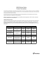
One Jake Brown Road
Old Bridge, NJ 08857-1000 USA
(800) 523-6049 • (732) 679-4000 • FAX: (732) 679-4353
www.blondertongue.com
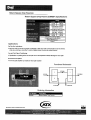
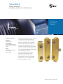
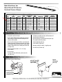
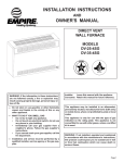
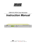
INSTRUCTION MANUAL
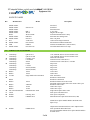
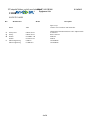
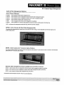
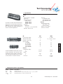
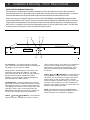
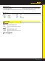
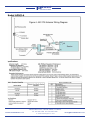
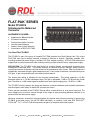
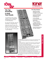
DA-33 Wideband Amplifier
Stock No. 4675A
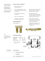
Description:
The DA-33 features a wide frequency bandwidth of 0.5 MHz to 300 MHz, 36 dB gain and 18 dB of continuously
variable gain control range. The DA-33 is ideal as a headend sub-channel return amplifier or on shipboard distribution systems requiring AM, shortwave and communications bands amplification.
Features:
• AM, Shortwave, Sub-Channel Amplification (0.5 MHz to 300 MHz)
• Externally Accessible Test Points Permit In-Service Testing.
• Aluminum Chassis Designed for Superior Heat Dissipation to Insure Component Reliability.
• Exceeds FCC Specs for Both Conducted and Radiated Interference @ Full Output Level.
• External Fuse for Ease of Replacement.
• LED Pilot Light.
• Line Transient Protection.
• Hybrid IC Circuitry for High Output with Low Distortion.
• Exceptional Temperature Stability Range of -20° C to +60° C.
• Designed for Critical Applications Requiring High Gain.
• Front Panel Gain Control for Easy Adjustment
651109400E
©2009 Blonder Tongue Laboratories, Inc. All rights reserved. Specifications are subject to change without notice. Trademarks are the property of their respective owner.
2
DA-33
Instruction Manual
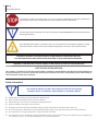
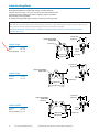
The STOP sign symbol is intended to alert you to the presence of REQUIRED operating and maintenance
(servicing) instructions that if not followed, may result in product failure or destruction.
The YIELD sign symbol in intended to alert you to the presence of RECOMMENDED operating and maintenance
(servicing) instructions.
The LIGHTNING flash symbol is intended to alert you to the presence of uninsulated "dangerous voltage"
within the product's enclosure that may be sufficient magnitude to constitute a risk of electrical shock.
TO REDUCE THE RISK OF ELECTRICAL SHOCK, DO NOT REMOVE COVER FROM THIS UNIT. NO USER-SERVICEABLE PARTS INSIDE. REFER SERVICING TO QUALIFIED SERVICE PERSONNEL.
WARNING: TO PREVENT FIRE OR SHOCK HAZARD, DO NOT EXPOSE THIS UNIT TO RAIN OR MOISTURE
NOTE TO CATV SYSTEM INSTALLER
This reminder is provided to call the CATV System Installer’s attention to Article 820-40 of the NEC that provides guidelines for
proper grounding and, in particular, specifies that the cable ground shall be connected to the grounding system of the building, as
close to the point of cable entry as practical.
Safety Instructions
You should always follow these instructions to help ensure
Against injury to yourself and damage to your equipment.
➥ Read all safety and operating instructions before you operate the unit.
➥ Retain all safety and operating instructions for future reference.
➥ Heed all warnings on the unit and in the safety and operating instructions.
➥ Follow all installation, operating, and use instructions.
➥ Unplug the unit from the AC power outlet before cleaning. Use only a damp cloth for cleaning the exterior of the unit.
➥ Do not use accessories or attachments not recommended by Blonder Tongue, as they may cause hazards, and will void the warranty.
➥ Do not operate the unit in high-humidity areas, or expose it to water or moisture.
➥ D
o not place the unit on an unstable cart, stand, tripod, bracket, or table. The unit may fall, causing serious personal injury and damage to the
unit. Install the unit only in a mounting rack designed for 19” rack-mounted equipment.
DA-33
Instruction Manual
Safety Instructions - continued
➥ D
o not block or cover slots and openings in the unit. These are provided for ventilation and protection from overheating. Never place the
unit near or over a radiator or heat register. Do not place the unit in an enclosure such as a cabinet without proper ventilation. Do not mount
equipment in the rack space directly above or below the unit.
➥ O
perate the unit using only the type of power source indicated on the marking label. Unplug the unit power cord by gripping the plug, not the
cord.
➥ T he unit is equipped with a three-wire ground-type plug. This plug will fit only into a ground-type power outlet. If you are unable to insert the
plug into the outlet, contact an electrician to replace the outlet. Do not defeat the safety purpose of the ground-type plug.
➥ R
oute power supply cords so that they are not likely to be walked on or pinched by items placed upon or against them. Pay particular attention
to cords at plugs, convenience receptacles, and the point where they exit from the unit.
➥ B
e sure that the outdoor components of the antenna system are grounded in accordance with local, federal, and National Electrical Code (NEC)
requirements. Pay special attention to NEC Sections 810 and 820. See the example shown in the following diagram:
➥ W
e strongly recommend using an outlet that contains surge suppression or ground fault protection. For added protection during a lightning
storm, or when the unit is left unattended and unused for long periods of time, unplug it from the wall outlet and disconnect the lines between
the unit and the antenna. This will prevent damage caused by lightning or power line surges.
➥ D
o not locate the antenna near overhead power lines or other electric light or power circuits, or where it can fall into such power lines or circuits.
When installing the antenna, take extreme care to avoid touching such power lines or circuits, as contact with them can be fatal.
➥ Do not overload wall outlets or extension cords, as this can result in a risk of fire or electrical shock.
➥ N
ever insert objects of any kind into the unit through openings, as the objects may touch dangerous voltage points or short out parts. This could
cause fire or electrical shock.
➥ D
o not attempt to service the unit yourself, as opening or removing covers may expose you to dangerous voltage and will void the warranty. Refer
all servicing to authorized service personnel.
➥ Unplug the unit from the wall outlet and refer servicing to authorized service personnel whenever the following occurs:
❏ The power supply cord or plug is damaged;
❏ Liquid has been spilled, or objects have fallen into the unit;
❏ The unit has been exposed to rain or water;
❏ The unit has been dropped or the chassis has been damaged;
❏ The unit exhibits a distinct change in performance.
➥ W
hen replacement parts are required, ensure that the service technician uses replacement parts specified by Blonder Tongue. Unauthorized
substitutions may damage the unit or cause electrical shock or fire, and will void the warranty.
➥ U
pon completion of any service or repair to the unit, ask the service technician to perform safety checks to ensure that the unit is in proper
operating condition.
Returning Product for Repair (or Credit)
A Return Material Authorization (RMA) Number is required on all products returned to Blonder Tongue, regardless if
the product is being returned for repair or credit. Before returning product, please contact the Blonder Tongue Service
Department at 1-800-523-6049, Ext. 4256 or visit our website: www.blondertongue.com for further information.
3
4
DA-33
Instruction Manual
Specifications
RF
Frequency Range: 0.5-300 MHz
Channel Loading: 35 Channels
Flatness: +/- 1 dB
Full Gain: 36 dB
Noise Figure: 5.5 dB
Output Level: +47 dBmV
Composite Triple Beat: -71 dB
Cross Modulation: -55 dB
Hum Modulation: -60 dB
Return Loss
Input: 16 dB
Output: 12 dB
General
Power Requirements: 105 to 130 VAC, 60 Hz
Operating Temperature: -40 to +65 degrees C
Mechanical
Dimensions (L x W x H): 11.5” x 7.125” x 3.25”
Weight: 5.75 lbs.
Connectors:
RF In/Out: F Female
In/Output -30 dB Test Points: F Female
One Jake Brown Road
Old Bridge, NJ 08857-1000 USA
(800) 523-6049 • (732) 679-4000 • FAX: (732) 679-4353
www.blondertongue.com
IZhi6XXZhhdg^Zh
H6",J!;6;;6B
M HeZX^[^XVi^dch
H6",J
G;
I]ZH6",J^hVkZghVi^aZha^YZhl^iX]ViiZcjVidg
i]VideZgViZhdkZgi]Z[gZfjZcXngVc\Zd[*id
.%%B=o#>iegdk^YZhVidiVaViiZcjVi^dcd[+'
Y7^c&Y7hiZeh#I]^hkVg^VWaZViiZcjVidg^hV
bjhi[dgiZhiWZcX]Veea^XVi^dch#
G;
;6B
I]Z;6;VcY;6B[^mZYViiZcjVidghegdk^YZ
VXXjgViZ ViiZcjVi^dc VcY ZmXZaaZci bViX]#
I]Z;6;hZg^Zh]Vh;[ZbVaZXdccZXidghVi
Wdi]ZcYh!l]^aZi]Z;6BhZg^Zh]VhdcZineZ
;bVaZVcYdcZ;[ZbVaZXdccZXidg#
<ZcZgVa
9^bZch^dchAmLm=/
+#'*m'#%%m&#&(^c#
&*.m*&m'.bb
LZ^\]i/ &&do#!(&(\gVbh
8dccZXidgh/;;ZbVaZ
;6;
;6B
*id-.%
*id&%%%
6iiZcjVi^dcKVajZhY7/
(
&!'!(!)!*!+!,!&%!'%
>beZYVcXZ"6aaEdgih±/
,*
,*
GZijgcAdhhY7
*id*%B=o/
*%id(%%B=o/
(%%id),%B=o/
),%id-.%B=o/
-.%id&%%%B=o/
'-
''
'%
&-
"
'&
'&
'&
&,
&+
'#*m%#*
'.m&(
'#%m%#*
*&m&(
%#,*
'&
;;ZbVaZ
%#,*
'&
;;ZbVaZ
;BVaZ
;gZfjZcXnGVc\ZB=o/
;6;
GZijgcAdhh
*id(%%B=o/''Y7
(%%id-%%B=o/'&Y7
-%%id.%%B=o/&)Y7
9^hig^Wji^dc
H6",J
;gZfjZcXnGVc\Z/*id.%%B=o
>chZgi^dcAdhh
B^c^bjb6iiZcjVi^dc
*B=o/%#'*Y7
''%B=o/%#*%Y7
)*%B=o/&#%%Y7
.%%B=o/&#*%Y7
6iiZcjVi^dc
IdiVa/+'Y7
>cXgZbZcih/&!'!(!+!&%!'%!'%Y7
>beZYVcXZ"6aaEdgih/,*±
<ZcZgVa
9^bZch^dchAmD#9#/
^c#
bb
LZ^\]i/
do
\
8dccZXidgh/
M DgYZg^c\>c[dgbVi^dcHeZX^[nKVajZ
BdYZa
HidX`Cd# 9ZhXg^ei^dc
H6",J
;6B
;6;
)&'&
)%%+6
()()
iiZcjVidg!Ha^YZHl^iX]
6
;^mZY6iiZcjVidgIneZÆ;Ç!BVaZ";ZbVaZ!KVajZh/&!'!(!)!*!+!,!&%!'%Y7
;^mZY6iiZcjVidg!IneZÆ;Ç!;ZbVaZ";ZbVaZKVajZh/(Y7
&,*
www.blondertongue.com • 800-523-6049
Product Specifications
2227K
CMRL RG6 QD 1000
Material ID: 4104504/10
RG 6 Type Quad Shield Plenum Video Coaxial Cable, cream jacket, 1000 ft (305 m) reel Construction Materials
Construction Type Nonarmored Center Conductor Material Copperclad steel wire Dielectric Material Foam FEP Inner Shield (Braid) Coverage 60 % Inner Shield (Braid) Gauge 34 AWG Inner Shield (Braid) Material Aluminum Inner Shield (Tape) Material Aluminum/Poly, bonded Jacket Material PVDF Outer Shield (Braid) Coverage 40 % Outer Shield (Braid) Gauge 34 AWG Outer Shield (Braid) Material Aluminum Outer Shield (Tape) Material Aluminum/Poly, nonbonded Dimensions
Cable Length 305 m | 1000 ft Cable Weight 30.00 lb/kft Diameter Over Center Conductor 1.0236 mm per 1 strand
0.0403 in per 1 strand Diameter Over Center Conductor Tolerance ±0.0004 in Diameter Over Dielectric 4.3180 mm | 0.1700 in Diameter Over Jacket 6.604 mm | 0.260 in Diameter Over Jacket Tolerance ±0.004 in Jacket Thickness 0.406 mm | 0.016 in Jacket Thickness, minimum spot 0.330 mm | 0.013 in Diameter Over Inner Shield (Braid) 5.131 mm | 0.202 in Diameter Over Outer Shield (Braid) 5.893 mm | 0.232 in Electrical Specifications
Capacitance 50.9 pF/m | 15.5 pF/ft Characteristic Impedance 75 ohm Characteristic Impedance Tolerance ±3 ohm Conductor dc Resistance 28.60 ohms/kft Dielectric Strength, conductor to shield 2500 Vdc Jacket Spark Test Voltage 2500 Vac Nominal Velocity of Propagation (NVP) 84 % Shield dc Resistance 5.30 ohms/kft Structural Return Loss 15 dB @ 1000–3000 MHz | 20 dB @ 5 –1000 MHz Structural Return Loss Test Method 100% Swept Tested Environmental Specifications
©2012 CommScope, Inc. All rights reserved. All trademarks identified by ® or ™ are registered trademarks, respectively, of CommScope.
All specifications are subject to change without notice. See www.commscope.com for the most current information. Revised: 2/1/2011
page 1 of 2
2/7/2012
Product Specifications
2227K CMRL RG6 QD 1000 - Material ID: 4104504/10
Environmental Space Plenum Flame Test Method CMP Operating Temperature 40 °C to +125 °C (40 °F to +257 °F) Safety Standard cETL | ETL UL Temperature Rating 125 °C | 257 °F General Specifications
Application Video Cable Type Series 6 Jacket Color Cream Product Number 2227K Center Conductor Gauge 18 AWG Center Conductor Type Solid Packaging Type Reel Mechanical Specifications
Minimum Bend Radius, loaded 20 times Minimum Bend Radius, unloaded 10 times Electrical Performance
Frequency
1 MHz
10 MHz
50 MHz
100 MHz
200 MHz
400 MHz
700 MHz
900 MHz
1000 MHz
1200 MHz
1450 MHz
1800 MHz
2200 MHz
2500 MHz
3000 MHz
Attenuation (dB/100 m)
1.25
2.30
4.85
6.59
9.38
13.87
19.55
22.83
24.44
27.06
30.64
35.06
37.85
38.38
42.87
Attenuation (dB/100 ft)
0.38
0.70
1.48
2.01
2.86
4.23
5.96
6.96
7.45
8.25
9.34
10.69
11.54
11.70
13.07
Regulatory Compliance/Certifications
Agency
RoHS 2002/95/EC
ISO 9001:2008
Classification
Compliant
Designed, manufactured and/or distributed under this quality management system
©2012 CommScope, Inc. All rights reserved. All trademarks identified by ® or ™ are registered trademarks, respectively, of CommScope.
All specifications are subject to change without notice. See www.commscope.com for the most current information. Revised: 2/1/2011
page 2 of 2
2/7/2012
Product Specifications
2287K
CMRL RG11 QD 1000
Material ID: 4103304/10
RG 11 Type Quad Shield Plenum Video Coaxial Cable, cream jacket, 1000 ft (305 m) reel Construction Materials
Construction Type Nonarmored Center Conductor Material Copperclad steel wire Dielectric Material Foam FEP Inner Shield (Braid) Coverage 60 % Inner Shield (Braid) Gauge 34 AWG Inner Shield (Braid) Material Aluminum Inner Shield (Tape) Material Aluminum/Poly Jacket Material PVDF Outer Shield (Braid) Coverage 40 % Outer Shield (Braid) Gauge 34 AWG Outer Shield (Braid) Material Aluminum Outer Shield (Tape) Material Aluminum/Poly, nonbonded Dimensions
Cable Length 305 m | 1000 ft Cable Weight 63.00 lb/kft Diameter Over Center Conductor 1.6281 mm per 1 strand
0.0641 in per 1 strand Diameter Over Dielectric 7.1120 mm | 0.2800 in Diameter Over Inner Shield (Tape) 7.112 mm | 0.280 in Diameter Over Jacket 9.449 mm | 0.372 in Diameter Over Jacket Tolerance ±0.008 in Jacket Thickness 0.508 mm | 0.020 in Jacket Thickness, minimum spot 0.406 mm | 0.016 in Diameter Over Inner Shield (Braid) 7.925 mm | 0.312 in Diameter Over Outer Shield (Braid) 8.433 mm | 0.332 in Electrical Specifications
Capacitance 52.5 pF/m | 16.0 pF/ft Characteristic Impedance 75 ohm Characteristic Impedance Tolerance ±3 ohm Conductor dc Resistance 11.00 ohms/kft Dielectric Strength, conductor to shield 4000 Vdc Jacket Spark Test Voltage 2500 Vac Nominal Velocity of Propagation (NVP) 84 % Shield dc Resistance 3.90 ohms/kft Structural Return Loss 15 dB @ 1000–3000 MHz | 20 dB @ 5 –1000 MHz Structural Return Loss Test Method 100% Swept Tested Environmental Specifications
©2012 CommScope, Inc. All rights reserved. All trademarks identified by ® or ™ are registered trademarks, respectively, of CommScope.
All specifications are subject to change without notice. See www.commscope.com for the most current information. Revised: 2/1/2011
page 1 of 2
2/7/2012
Product Specifications
2287K CMRL RG11 QD 1000 - Material ID: 4103304/10
Environmental Space Plenum Flame Test Method CMP Safety Standard cETL | ETL UL Temperature Rating 125 °C | 257 °F General Specifications
Application Video Cable Type Series 11 Jacket Color Cream Product Number 2287K Center Conductor Gauge 14 AWG Center Conductor Type Solid Packaging Type Reel Mechanical Specifications
Minimum Bend Radius, loaded 20 times Minimum Bend Radius, unloaded 10 times Electrical Performance
Frequency
1 MHz
10 MHz
50 MHz
100 MHz
200 MHz
400 MHz
700 MHz
900 MHz
1000 MHz
1450 MHz
1800 MHz
2200 MHz
3000 MHz
Attenuation (dB/100 ft)
0.15
0.45
0.90
1.28
1.85
2.75
3.92
4.72
5.04
6.67
7.71
8.50
9.88
Regulatory Compliance/Certifications
Agency
RoHS 2002/95/EC
ISO 9001:2008
Classification
Compliant
Designed, manufactured and/or distributed under this quality management system
©2012 CommScope, Inc. All rights reserved. All trademarks identified by ® or ™ are registered trademarks, respectively, of CommScope.
All specifications are subject to change without notice. See www.commscope.com for the most current information. Revised: 2/1/2011
page 2 of 2
2/7/2012
QR 320 Series Cables
Product Descriptions
CommScope’s patented QR® coaxial cable was developed to meet the increasing demands of tomorrow’s broadband
networks. QR has the highest reliability and flexibility of any Trunk and Distribution coaxial cable, low RF attenuation
and an unprecedented 10 year warranty.
All QR cable products offer tough polyethylene jackets and a standardized, environmentally sealed connector
interface engineered for reliability and craft friendliness.
QR 320 is optimized for use in multiple dwelling units (MDU) and feeder applications. QR 320 offers unmatched
flexibility, reliability and cost effectiveness.
Standard QR Construction
A precision aluminum strip is formed and continuously RF welded around a high compression micro-cellular foam
dielectric core, eliminating RF leakage, and the rigidity common in traditional coaxial products. The shield is fully
bonded to the dielectric core, as is the copper clad aluminum center conductor. A tough polyethylene jacket is
applied standard, which enhances cable reliability and allows QR’s unique connector technology to form an environmental seal.
Aerial Installation
Part #
QR 320 JCA
QR 320 JCAM109
Description
Offers all of QR's
standard construction
features
QR 320 JCAM083 EHS
(also available)
Has an integrated figure 8
galvanized solid steel
messenger for self-supporting
applications
Part #
Description
Cable Weight
Shipping Wteight
Standard Length
47 lbs/kft
(70 kg/km)
63 lbs/kft
(94 kg/km)
3700 ft
(1128m)
88 lbs/kft
(131 kg/km)
107 lbs/kft
(159 kg/km)
3700 ft
(1128m)
73 lbs/kft
(109 kg/km)
90 lbs/kft
(134 kg/km)
3700 ft
(1128m)
Shipping Wteight
Standard Length
63 lbs/kft
(94 kg/km)
3700 ft
(1128m)
Underground Installation
QR 320 JCASS
Cable Weight
Features CommScope's
Migra-Heal floodant
47 lbs/kft
that seas jacket damage
(70 kg/km)
to inhibit corrosion
Indoor/Riser Installation
Part #
Description
Cable Weight
Shipping Wteight
Standard Length
QR 320 JCAR
has a flame-retardant
polyethylene jacket that
meets NEC's CATVR rating
56 lbs/kft
(83 kg/km)
72 lbs/kft
(112 kg/km)
3700 ft
(1128m)
QR (JCASS)
High Density Polythylene Conduit
Polythylene Jacket
Aluminum Outer Jacket
Center Conductor
Dielectric
Dielectric Adhesive
Flooding
CommScope’s patented QR® coaxial cable was developed to meet the increasing demands of tomorrow’s
broadband networks. QR has the highest reliability and flexibility of any coaxial cable, low RF attenuation and an
unprecedented 10-year warranty. QR coaxial cable offers lower attenuation than larger traditional products,
with unmatched flexibility, reliability and cost effectiveness. CommScope offers four standard sizes (540, 715,
860 and 1125) of QR Cable-InConduit, each optimized for a specific use.
QR 540 JCASS
Size
1"
1 1/4"
1 1/2"
2"
1"
1 1/4"
11/2"
2"
Wall
Thickness
Wall
Rating
SDR 13.5
SDR 11
SCH 40
SDR 13.5
SCH 40
SDR 11
SDR 13.5
SCH 40
SDR 11
SCH 40
SDR 13.5
SDR 11
Medium
Heavy
X-Heavy
Medium
Heavy
X-Heavy
Medium
Heavy
X-Heavy
Medium
Heavy
X-Heavy
SDR 13.5
SDR 11
SCH 40
SDR 13.5
SCH 40
SDR 11
SDR 13.5
SCH 40
SDR 11
SCH 40
SDR 13.5
SDR 11
Medium
Heavy
X-Heavy
Medium
Heavy
X-Heavy
Medium
Heavy
X-Heavy
Medium
Heavy
X-Heavy
QR 715 JCASS
Nominal
Nominal
Reel Size
Weight*
Reel Size
Weight*
Length
Length
(FDT) (in)
lbs/ft
(FDT) (in)
lbs/ft
(ft)
(ft)
3,700
63 x 30 x 40
261
NA
NA
NA
3,700
63 x 30 x 40
296
NA
NA
NA
3,700
63 x 30 x 40
311
NA
NA
NA
3,700
80 x 40 x 38
357
3,000
68 x 30 x 40
409
3,700
80 x 40 x 38
387
3,000
68 x 30 x 40
439
3,700
80 x 40 x 38
412
3,000
68 x 30 x 40
464
3,700
90 x 42 x 40
436
3,000
90 x 42 x 40
488
3,700
90 x 42 x 40
445
3,000
90 x 42 x 40
497
3,700
90 x 42 x 40
508
3,000
90 x 42 x 40
560
3,700 102 x 48 x 42
564
3,000 102 x 48 x 42
616
3,700 102 x 48 x 42
624
3,000 102 x 48 x 42
676
3,700 102 x 48 x 42
732
3,000 102 x 48 x 42
784
QR 860 JCASS
QR 1125 JCASS
NA
NA
NA
NA
NA
NA
2700
2700
2700
2700
2700
2700
NA
NA
NA
NA
NA
NA
80 x 40 x 38
80 x 40 x 38
80 x 40 x 38
102 x 48 x 42
102 x 48 x 42
102 x 48 x 42
NA
NA
NA
NA
NA
NA
558
567
630
686
746
854
NA
NA
NA
NA
NA
NA
NA
NA
NA
3000
3000
3000
NA
NA
NA
NA
NA
NA
NA
NA
NA
102 x 48 x 42
102 x 48 x 42
102 x 48 x 42
NA
NA
NA
NA
NA
NA
NA
NA
NA
815
875
983
Trunk & Distribution Cable Catalog Numbering Key
QR 540 J CA SS - T
Tracer
Floodant
Copper Aluminum
Size
PE Jacket
(diameter over shield)
-
Suffix
- J - Jacketed
- CA - Copper Aluminum
- SS - Miagra-Heal Flooding Compound
- T - Tracer
- M - Messenger
- EHS - Extra High Strength
320
540
715
860
1125
QR Aerial Construction Configurations
Polyethylene Jacket
Aluminum Outer Conductor
QR JCA
Center Conductor
Dielectric
Dielectric Adhesive
QR JCAM
(Solid Messenger)
Integrated Figure 8 Solid
Galvanized Steel Messenger
QR Underground Construction Configurations
Migra-Heal Flooding Compound
QR JCASS
Polypropylene Tape
Inner Polythylene Jacket
QR 2J (MA) CASS
Ripcord
Bonded Corrugated Chrome
Plated Steel Armor
QR JACASS
QR 320 Series Cables
Product Specifications
Physical Dimensions
Component
Inches
Nominal Center Conductor Diameter
0.071
Nominal Diameter Over Dielectric
0.294
Nominal Diameter Over Outer Conductor
0.320
Nominal Outer Conductor Thickness
0.013
Nominal Diameter Over jacket
0.395
Nominal Jacket Wall Thickness
0.0375
Messenger Version
0.109
Diameter of Steel Messenger
0.083
Mechanical Characteristics
Minimum Bending Radius
Maximum Pulling Tension
Minimum Breaking Strength
of Messenger
(109)
(.083)
Attenuation @ 68°F (20°C)
mm
1.80
7.47
8.13
0.34
10.03
0.89
2.77
2.11
2.0 in
120 lbs
50.8 mm
54.5 kgf
1,800 lbs
1,000 lbs
816 kgf
453 kgf
Electrical Characteristics
Capacitance
Impedance
Velocity of Propagation
15.3 ± 1.0 p f /f t
50 ± 3.0 n f /f t
75 ± 3 ohms
87%
Maximum D.C. Resistance @ 68°F (20°C)
Inner Conductor
Outer Conductor
Loop
3.2/8 ohms/1000ft
0.99 ohms/1000ft.
4.27 ohms/1000ft
10.76 ohms/km
3.25 ohms/km
14.01 ohms/km
Frequency
(Mhz)
5
30
45
50
55
83
108
150
181
193
211
220
250
270
300
325
350
375
400
425
450
500
550
600
750
865
1000
(db/100 ft)
Max
0.24
0.62
0.76
0.80
0.84
1.07
1.22
1.45
1.60
1.65
1.73
1.76
1.86
1.94
2.04
2.17
2.25
2.30
2.38
2.45
2.52
2.72
2.85
2.98
3.34
3.62
3.89
(db/100 m)
Max.
0.79
2.03
2.49
2.62
2.76
3.51
4.00
4.76
5.25
5.41
5.68
5.77
6.10
6.37
6.69
7.12
7.38
7.55
7.81
8.04
8.27
8.92
9.35
9.78
10.96
11.87
12.76
Product Specifications
F1160BVR
Material ID: 7736703
75 Ohm Coaxial Drop Cable, Series 11, black flame retardant PVC jacket Construction Materials
Center Conductor Material Copperclad steel Dielectric Material Foam PE Inner Shield (Braid) Coverage 60 % Inner Shield (Braid) Gauge 34 AWG Inner Shield (Braid) Material Aluminum Inner Shield (Tape) Material Aluminum/Polymer/Aluminum (APA) bonded Jacket Material Fire retardant PVC Dimensions
Diameter Over Center Conductor, nominal 1.626 mm | 0.064 in Diameter Over Dielectric, nominal 7.112 mm | 0.280 in Diameter Over Inner Shield (Tape), nominal 7.290 mm | 0.287 in Diameter Over Jacket, nominal 10.160 mm | 0.400 in Jacket Thickness, nominal 1.0668 mm | 0.0420 in Shipping Weight 59.00 lb/kft Electrical Specifications
dc Resistance, Inner Conductor, nominal 12.50 ohms/kft dc Resistance, Outer Conductor, nominal 7.00 ohms/kft dc Resistance, Loop, nominal 19.50 ohms/kft dc Resistance Note Nominal values based on a standard condition of 20 °C (68 °F) Capacitance 53.1 pF/m | 16.2 pF/ft Characteristic Impedance 75 ohm Characteristic Impedance Tolerance ±3 ohm Nominal Velocity of Propagation (NVP) 85 % Environmental Specifications
Environmental Space Indoor | Riser Flame Test Listing CATVR | NEC Article 820 General Specifications
Cable Type Series 11 Packaging Type Reel Shield Construction Type Dual shield Center Conductor Gauge 14 AWG Center Conductor Type Solid Jacket Color Black Jacket Marking Feet Warranty One year ©2012 CommScope, Inc. All rights reserved. All trademarks identified by ® or ™ are registered trademarks, respectively, of CommScope.
All specifications are subject to change without notice. See www.commscope.com for the most current information. Revised: 11/11/2011
page 1 of 2
2/3/2012
Product Specifications
F1160BVR - Material ID: 7736703
Electrical Performance
Frequency
5 MHz
55 MHz
83 MHz
187 MHz
211 MHz
250 MHz
300 MHz
350 MHz
400 MHz
450 MHz
500 MHz
550 MHz
600 MHz
750 MHz
865 MHz
1000 MHz
Attenuation (dB/100 m)
1.25
3.15
3.87
5.74
6.23
6.72
7.38
7.94
8.53
9.02
9.51
9.97
10.43
11.97
13.05
14.27
Attenuation (dB/100 ft)
0.38
0.96
1.18
1.75
1.90
2.05
2.25
2.42
2.60
2.75
2.90
3.04
3.18
3.65
3.98
4.35
* Attenuation listed represents maximum values at standard condition of 20 °C (68 °F) Regulatory Compliance/Certifications
Agency
RoHS 2002/95/EC
ISO 9001:2008
Classification
Compliant
Designed, manufactured and/or distributed under this quality management system
©2012 CommScope, Inc. All rights reserved. All trademarks identified by ® or ™ are registered trademarks, respectively, of CommScope.
All specifications are subject to change without notice. See www.commscope.com for the most current information. Revised: 11/11/2011
page 2 of 2
2/3/2012
Product Specifications
F11SSV
Material
ID: 4564604
75 Ohm Coaxial Drop Cable, Series 11, black PVC jacket Construction Materials
Center Conductor Material Copperclad steel Dielectric Material Foam PE Inner Shield (Braid) Coverage 60 % Inner Shield (Braid) Gauge 34 AWG Inner Shield (Braid) Material Aluminum Inner Shield (Tape) Material Aluminum/Polymer/Aluminum (APA) bonded Jacket Material PVC Outer Shield (Braid) Coverage 40 % Outer Shield (Braid) Gauge 34 AWG Outer Shield (Braid) Material Aluminum Outer Shield (Tape) Material Aluminum/Polymer/Aluminum (APA) Dimensions
Diameter Over Center Conductor, nominal 1.626 mm | 0.064 in Diameter Over Dielectric, nominal 7.112 mm | 0.280 in Diameter Over Inner Shield (Tape), nominal 7.290 mm | 0.287 in Diameter Over Jacket, nominal 10.338 mm | 0.407 in Jacket Thickness, nominal 0.9398 mm | 0.0370 in Shipping Weight 72.00 lb/kft Electrical Specifications
dc Resistance, Inner Conductor, nominal 12.50 ohms/kft dc Resistance, Outer Conductor, nominal 3.70 ohms/kft dc Resistance, Loop, nominal 16.20 ohms/kft dc Resistance Note Nominal values based on a standard condition of 20 °C (68 °F) Capacitance 53.1 pF/m | 16.2 pF/ft Characteristic Impedance 75 ohm Characteristic Impedance Tolerance ±3 ohm Nominal Velocity of Propagation (NVP) 85 % Environmental Specifications
Environmental Space Indoor General Specifications
Cable Type Series 11 Packaging Type Reel Shield Construction Type Quad shield Center Conductor Gauge 14 AWG Center Conductor Type Solid Jacket Color Black ©2012 CommScope, Inc. All rights reserved. All trademarks identified by ® or ™ are registered trademarks, respectively, of CommScope.
All specifications are subject to change without notice. See www.commscope.com for the most current information. Revised: 11/11/2011
page 1 of 2
2/7/2012
Product Specifications
F11SSV - Material ID: 4564604
Jacket Marking Feet Warranty One year Electrical Performance
Frequency
5 MHz
55 MHz
83 MHz
187 MHz
211 MHz
250 MHz
300 MHz
350 MHz
400 MHz
450 MHz
500 MHz
550 MHz
600 MHz
750 MHz
865 MHz
1000 MHz
Attenuation (dB/100 m)
1.25
3.15
3.87
5.74
6.23
6.72
7.38
7.94
8.53
9.02
9.51
9.97
10.43
11.97
13.05
14.27
Attenuation (dB/100 ft)
0.38
0.96
1.18
1.75
1.90
2.05
2.25
2.42
2.60
2.75
2.90
3.04
3.18
3.65
3.98
4.35
* Attenuation listed represents maximum values at standard condition of 20 °C (68 °F) Regulatory Compliance/Certifications
Agency
RoHS 2002/95/EC
ISO 9001:2008
Classification
Compliant
Designed, manufactured and/or distributed under this quality management system
©2012 CommScope, Inc. All rights reserved. All trademarks identified by ® or ™ are registered trademarks, respectively, of CommScope.
All specifications are subject to change without notice. See www.commscope.com for the most current information. Revised: 11/11/2011
page 2 of 2
2/7/2012
F59 HEC-2 VV HEADEND CABLE
75 Ohm Coaxial Cable
Drop Cable
1100 CommScope Place
Hickory, NC 28603
(800) 982-1708
(828) 324-2200
Fax: (828) 324-3400
Int’l Fax: (828) 323-4989
www.commscope.com
CommScope Properties, LLC
All Rights Reserved
PRODUCT DESCRIPTION:
BONDED LAMINATED ALUMINUM TAPE, 95% BRAID,
LAMINATED ALUMINUM TAPE, 95% BRAID,
FLAME RETARDANT PVC JACKET
CENTER CONDUCTOR:
20 AWG SILVER PLATED COPPER COVERED STEEL
NOMINAL DIAMETER: 0.032” (0.81 mm)
DIELECTRIC:
GAS EXPANDED POLYETHYLENE
NOMINAL DIAMETER OVER DIELECTRIC: 0.144” (3.66 mm)
SHIELD:
1S SHIELD: ALUMINUM LAMINATED TAPE BONDED
TO THE DIELECTRIC
NOMINAL DIAMETER OVER TAPE: 0.151” (3.84 mm)
2nd SHIELD: 34 AWG ALUMINUM BRAID WIRE
95% COVERAGE
3RD SHIELD: ALUMINUM LAMINATED TAPE
4TH SHIELD: 34 AWG ALUMINUM BRAID WIRE
95% COVERAGE
Center Conductor
Dielectric
Bonded Aluminum
Laminated Tape
Aluminum
Braided Shield
Laminated Aluminum
Tape
Aluminum
Braided Shield
JACKET:
FLAME RETARDANT PVC JACKET (AVAILABLE IN 12 COLORS)
NOMINAL DIAMETER OVER JACKET: 0.270” (6.86 mm)
ELECTRICAL PROPERTIES:
IMPEDANCE:
VELOCITY OF PROPAGATION:
ATTENUATION @ 68°F (20°C):
Jacket
75 +/- 3 Ohms
85% NOMINAL
@ Frequency MHz
5 MHz
55 MHz
83 MHz
187 MHz
211 MHz
250 MHz
300 MHz
350 MHz
400 MHz
450 MHz
500 MHz
550 MHz
600 MHz
750 MHz
865 MHz
1000 MHz
dB/100 ft. (MAX.)
0.86 dB
2.05 dB
2.45 dB
3.60 dB
3.80 dB
4.10 dB
4.45 dB
4.80 dB
5.10 dB
5.40 dB
5.70 dB
5.95 dB
6.20 dB
6.97 dB
7.52 dB
8.12 dB
dB/100 meters (MAX.)
2.82 dB
6.73 dB
8.04 dB
11.81 dB
12.47 dB
13.45 dB
14.60 dB
15.75 dB
16.73 dB
17.72 dB
18.70 dB
19.52 dB
20.34 dB
22.87 dB
24.67 dB
26.64 dB
Drawing not to scale.
Specifications subject to change.
Revision: 08/26/08
Product Specifications
F6SSV
Material
ID: 4561004
75 Ohm Coaxial Drop Cable, Series 6, black PVC jacket Construction Materials
Center Conductor Material Copperclad steel Dielectric Material Foam PE Inner Shield (Braid) Coverage 60 % Inner Shield (Braid) Gauge 34 AWG Inner Shield (Braid) Material Aluminum Inner Shield (Tape) Material Aluminum/Polymer/Aluminum (APA) bonded Jacket Material PE Outer Shield (Braid) Coverage 40 % Outer Shield (Braid) Gauge 34 AWG Outer Shield (Braid) Material Aluminum Outer Shield (Tape) Material Aluminum/Polymer/Aluminum (APA) Dimensions
Diameter Over Center Conductor, nominal 1.016 mm | 0.040 in Diameter Over Dielectric, nominal 4.572 mm | 0.180 in Diameter Over Inner Shield (Tape), nominal 4.750 mm | 0.187 in Diameter Over Jacket, nominal 7.544 mm | 0.297 in Jacket Thickness, nominal 0.7620 mm | 0.0300 in Shipping Weight 39.00 lb/kft Electrical Specifications
dc Resistance, Inner Conductor, nominal 30.50 ohms/kft dc Resistance, Outer Conductor, nominal 5.20 ohms/kft dc Resistance, Loop, nominal 35.70 ohms/kft dc Resistance Note Nominal values based on a standard condition of 20 °C (68 °F) Capacitance 53.1 pF/m | 16.2 pF/ft Characteristic Impedance 75 ohm Characteristic Impedance Tolerance ±3 ohm Nominal Velocity of Propagation (NVP) 85 % Environmental Specifications
Environmental Space Buried General Specifications
Cable Type Series 6 Packaging Type Reel Shield Construction Type Quad shield Center Conductor Gauge 18 AWG Center Conductor Type Solid Jacket Color Black ©2012 CommScope, Inc. All rights reserved. All trademarks identified by ® or ™ are registered trademarks, respectively, of CommScope.
All specifications are subject to change without notice. See www.commscope.com for the most current information. Revised: 11/11/2011
page 1 of 2
2/7/2012
Product Specifications
F6SSV - Material ID: 4561004
Jacket Marking Feet Warranty One year Electrical Performance
Frequency
5 MHz
55 MHz
83 MHz
187 MHz
211 MHz
250 MHz
300 MHz
350 MHz
400 MHz
450 MHz
500 MHz
550 MHz
600 MHz
750 MHz
865 MHz
1000 MHz
Attenuation (dB/100 m)
1.90
5.25
6.40
9.35
10.00
10.82
11.64
12.63
13.61
14.43
15.29
16.08
16.73
18.54
20.01
21.49
Attenuation (dB/100 ft)
0.58
1.60
1.95
2.85
3.05
3.30
3.55
3.85
4.15
4.40
4.66
4.90
5.10
5.65
6.10
6.55
* Attenuation listed represents maximum values at standard condition of 20 °C (68 °F) Regulatory Compliance/Certifications
Agency
RoHS 2002/95/EC
ISO 9001:2008
Classification
Compliant
Designed, manufactured and/or distributed under this quality management system
©2012 CommScope, Inc. All rights reserved. All trademarks identified by ® or ™ are registered trademarks, respectively, of CommScope.
All specifications are subject to change without notice. See www.commscope.com for the most current information. Revised: 11/11/2011
page 2 of 2
2/7/2012
DQT1000 Digital to QAM Transcoder
MQM1000 Multiplexing QAM Modulator
Instruction Manual
TM is a trademark of R.L. Drake LLC
is a registered trademark of R.L. Drake LLC
© Copyright 2007 R.L. Drake LLC
P/N: 3852395C-09-2007
Printed in U.S.A.
2
Caution Statements
WARNING: TO PREVENT FIRE OR
ELECTRICAL SHOCK DO NOT
EXPOSE TO RAIN OR MOISTURE
A product and cart combination should be moved
with care. Quick stops, excessive force and uneven
surfaces may cause the product and cart combination to overturn.
RISK OF ELECTRIC SHOCK
DO NOT OPEN
The lightning flash with arrow head symbol, within
an equilateral triangle, is intended to alert the user
to the presence of uninsulated "dangerous voltage"
within the product's enclosure that may be of
sufficient magnitude to constitute a risk of electric
shock to persons.
CAUTION: TO REDUCE THE RISK OF ELECTRIC
SHOCK,
DO NOT REMOVE COVER
NO USER-SERVICEABLE PARTS INSIDE
REFER SERVICING TO QUALIFIED PERSONNEL
The exclamation point within an equilateral triangle
is intended to alert the user to the presence of
important operating and maintenance (servicing)
instructions in the literature accompanying
the product.
CAUTION
WARNING: TO REDUCE THE RISK OF FIRE OR ELECTRIC SHOCK, DO NOT EXPOSE THIS PRODUCT
TO RAIN OR MOISTURE.
DO NOT OPEN THE CABINET, REFER SERVICING TO QUALIFIED PERSONNEL ONLY.
CAUTION: TO PREVENT ELECTRIC SHOCK, DO NOT USE THIS (POLARIZED) PLUG WITH AN EXTENSION
CORD RECEPTACLE OR OTHER OUTLET UNLESS THE BLADES CAN BE FULLY INSERTED TO
PREVENT BLADE EXPOSURE.
ATTENTION: POUR PREVENIR LES CHOCS ELECTRIQUES, NE PAS UTILISER CETTE FICHE POLARISEE
AVEC UN PROLONGATEUR, UNE PRISE DE COURANT OU UNE AUTRE SORTIE DE COURANT, SAUF SI LES LAMES PEUVENT ETRE INSEREES A FOND SANS EN LAISSER AUCUNE
PARTIE A DECOUVERT.
The DQT1000 and MQM1000 have been designed to comply with, and tested to confirm compliance to,
the following satety regulations:
ANSI/UL 60065, 7th Edition, dated 06/30/2004, rev. 11/20/2006.
CAN/CSA - C22.2 No. 60065:03 (2006).
Important Safety Instructions
1. Read Instructions—All the safety and operating instructions should be read
before the product is operated.
2. Retain Instructions—The safety and operating instructions should be
retained for future reference.
3. Heed Warnings—All warnings on the product and in the operating
instructions should be adhered to.
4. Follow Instructions—All operating and use instructions should be followed.
5. Cleaning—Unplug this product from the wall outlet before cleaning. Do not
use liquid cleaners or aerosol cleansers. Use a damp cloth for cleaning.
6. Attachments—Do not use attachments that are not recommended by the
product manufacturer as they may cause hazards.
7. Water and Moisture—Do not use this product near water—for example,
near a bathtub, wash bowl, kitchen sink or laundry tub; in a wet basement;
or near a swimming pool; and the like.
8. Accessories—Do not place this product on an unstable cart, stand, tripod,
bracket, or table. The product may fall, causing serious injury to a child or adult,
and serious damage to the product. Use only with a cart, stand, tripod, bracket,
or table recommended by the manufacturer, or sold with the product. Any
mounting of the product should follow the manufacturer's instructions, and
should use a mounting accessory recommended by the manufacturer.
9. A product and cart combination should be moved with care. Quick stops,
excessive force, and uneven surfaces may cause the product and cart
combination to overturn.
10. Ventilation—Slots and openings in the cabinet are provided for ventilation
and to ensure reliable operation of the product and to protect it from
overheating, and these openings must not be blocked or covered. The
openings should never be blocked by placing the product on a bed, sofa, rug,
or similar surface. This product should not be placed in a built-in installation
such as bookcase or rack unless proper ventilation is provided or the
manufacturer's instructions have been adhered to.
11. Power Sources—This product should be operated only from the type of
power source indicated on the marking label. If you are not sure of the type of
power supplied to your home, consult your product dealer or local power
company. For products intended to operate from battery power, or other
sources, refer to the operating instructions.
12. Grounding or Polarization—This product may be equipped with a
polarized alternating-current line plug (a plug having one blade wider than the
other). This plug will fit into the power outlet only one way. This is a safety
feature. If you are unable to insert the plug fully into the outlet, try reversing
the plug. If the plug should still fail to fit, contact your electrician to replace
your obsolete outlet. Do not defeat the safety purpose of the polarized plug.
Alternate Warnings—If this product is equipped with a three-wire groundingtype plug, a plug having a third (grounding) pin, the plug will only fit into a
grounding-type power outlet. This is a safety feature. If you are unable to insert
the plug into the outlet, contact your electrician to replace your obsolete outlet.
Do not defeat the safety purpose of the grounding-type plug.
12 a. Mise à la terre ou Polarisation—Cet appareil est équipé avec un cordon
d'alimentation à trois fils. Il est a brancher sur une prise ayant un connecteur
a la terre. Assurez-vous que la connection a la terre ne manque pas.
13. Power-Cord Protection—Power-supply cords should be routed so that
they are not likely to be walked on or pinched by items placed upon or against
them, paying particular attention to cords at plugs, convenience receptacles,
and the point where they exit from the product.
3
14. Outdoor Antenna Grounding—If an outside antenna or cable system is
connected to the product, be sure the antenna or cable system is grounded so
as to provide some protection against voltage surges and built-up static
charges. Article 810 of the National Electrical Code, ANSI/NFPA 70, provides
information with regard to proper grounding of the mast and supporting
structure, grounding of the lead-in wire to an antenna discharge unit, size of
grounding conductors, location of antenna-discharge unit, connection to
grounding electrodes, and requirements for the grounding electrode.
See Figure A.
15. Lightning—For added protection for this product during a lightning storm,
or when it is left unattended and unused for long periods of time, unplug it from
the wall outlet and disconnect the antenna or cable system. This will prevent
damage to the product due to lightning and power-line surges.
16. Power Lines—An outside antenna system should not be located in the
vicinity of overhead power lines, other electric light or power circuits, where it
can fall into such power lines or circuits. When installing an outside antenna
system, extreme care should be taken to keep from touching such power lines
or circuits as contact with them may be fatal.
17. Overloading—Do not overload wall outlets, extension cords, or integral
convenience receptacles as this can result in a risk of fire or electric shock.
18. Object and Liquid Entry—Never push objects of any kind into this product
through openings as they may touch dangerous voltage points or short-out
parts that could result in a fire or electric shock. Never spill liquid of any kind
on the product.
19. Servicing—Do not attempt to service this product yourself as opening
or removing covers may expose you to dangerous voltage or other hazards.
Refer all servicing to qualified service personnel.
20. Damage Requiring Service—Unplug this product from the wall outlet and
refer servicing to qualified service personnel under the following conditions:
a. When the power-supply cord or plug is damaged,
b. If liquid has been spilled, or objects have fallen into the product,
c. If the product has been exposed to rain or water,
d. If the product does not operate normally by following the operating
instructions. Adjust only those controls that are covered by the operating
instructions as an improper adjustment of other controls may result in damage
and will often require extensive work by a qualified technician to restore the
product to its normal operation,
e. If the product has been dropped or damaged in any way, and
f. When the product exhibits a distinct change in performance—this indicates
a need for service.
21. Replacement Parts—When replacement parts are required, be sure the
service technician has used replacement parts specified by the manufacturer
or have the same characteristics as the original part. Unauthorized substitutes
may result in fire, electric shock or other hazards.
22. Safety Check—Upon completion of any service or repairs to this product,
ask the service technician to perform safety checks to determine that the
product is in proper operating condition.
23. Wall or Ceiling Mounting—The product should be mounted to a wall or
ceiling only as recommended by the manufacturer.
24. Heat—The product should be situated away from heat sources such as
radiators, heat registers, stoves, or other products (including amplifiers) that
produce heat.
Figure A
Example of antenna grounding as per National Electrical Code, ANSI/NFPA 70
NOTE TO CATV SYSTEM INSTALLERS:
THIS REMINDER IS PROVIDED TO CALL THE
CATV SYSTEM INSTALLER'S ATTENTION TO
ARTICLE 820 - 40 OF THE NEC THAT
PROVIDES GUIDELINES FOR PROPER
GROUNDING AND, IN PARTICULAR,
SPECIFIES THAT THE CABLE GROUND SHALL
BE CONNECTED TO THE
GROUNDING
SYSTEM OF THE BUILDING, AS CLOSE TO
THE POINT OF CABLE ENTRY AS PRACTICAL.
ANTENNA
LEAD IN
WIRE
GROUND CLAMP
ANTENNA
DISCHARGE UNIT
(NEC SECTION 810-20)
ELECTRIC
SERVICE
EQUIPMENT
GROUNDING CONDUCTORS
(NEC SECTION 810-21)
GROUND CLAMPS
NEC - NATIONAL ELECTRIC CODE
POWER SERVICE GROUNDING
ELECTRODE SYSTEM
(NEC ART 250, PART H)
4
Table of Contents / Specifications
TABLE OF CONTENTS
2
3
4
5
6
Caution Statements
Important Safety Instructions
Table of Contents / Specifications
General Description
Installation and Mounting / Front Panel Controls
7
8
12
13
14
Rear Panel Controls and Connections
Setup and Programming
Operation / Additional Features
Service / If You Need To Call For Help
Warranty
SPECIFICATIONS
DEMODULATOR (S)
DQT1000 ONLY:
Input Frequency Range:
Channel Plans (Menu selectable):
Input Channel Bandwidth:
Input RF Level Range:
Minimum Input Level per Mode:
Maximum Input Power (sum of all channels):
Input Impedance:
Image rejection:
Adjacent Channel Rejection:
Noise Figure:
Demodulation Modes:
Symbol Rates:
Equalizer Span:
Not present - MQM1000
54 to 864 MHz.
Std. CATV, HRC, IRC, or Broadcast
6 MHz.
-28 dBmV to +30 dBmV
8VSB: -28dBmV, 16VSB: -25dBmV,
64QAM: -20dBmV, 256QAM: -15 dBmV.
Not to exceed -16 dBm.
75 Ohms with Return Loss typically 8 dB.
40 dB.
60 dB
Less than 12 dB.
8VSB,16VSB - ATSC
16QAM, 32QAM, 64QAM, 128QAM, or 256QAM - ITUA
64QAM, 256QAM, - ITUB
Commonly used presets and user programmable.
-6 µS to +40 µS.
ASI INPUTS
MQM1000-Two Inputs 270 Mbps with desired transport stream of
DQT1000 ASI Option: 10.76 MS/s, ATSC, 19.37 Mbps
NULL PACKET PROCESSING: DQT1000 and MQM1000 (fixed output clock mode)
QAM MODULATOR
Modulation Modes: 16QAM, 32QAM, 64QAM, 128QAM, 256QAM, 512QAM or
1024QAM. (See page 9 for all available combinations of QAM
modes and FEC.)
Symbol Rate: 1 Ms/s to 7 Ms/s.
FEC: ITUA (DVB) or ITUB (DigiCipher II).
I/Q Phase Error: Less than 1 degree.
Carrier Suppression: 45 dB.
Channel Amplitude Error: Less than 1 dB.
MER: Greater than 38 dB with blind equalizer.
ANALOG EAS IF INPUT
Operating Input Level: +30 dBmV ±5 dB at 45.75 MHz, 75 Ohms
Auto Switching Level: + 20 dBmV minimum.
UPCONVERTER RF OUTPUT
Output Frequency Range:
Channel Plan:
FCC offsets:
Frequency Stability:
Maximum Output Level:
Minimum Output Level:
Output Level Accuracy:
Output Impedance:
54 MHz to 1002 MHz.
Std. CATV, HRC, IRC, or Broadcast
Automatic, +12.5 or +25 kHz
± 5 ppm.
+ 61 dBmV minimum, adjustable downward.
+ 45 dBmV.
± 1 dB.
75 Ohms with return loss better than 14 dB
(within output filter passband).
Spurious Outputs: -60 dBc from 40 MHz to 1000 MHz.
Broadband Noise: Less than -12 dBmV (6 MHz BW @ ±12 MHz).
Phase Noise: -101 dBc @ 10 kHz offset
RS232 CONTROL
Data Link: 2400, 4800, 9600, or 19,200 baud interface via serial cable.
RS232 Input: DB-9 connector for connection to modem or PC.
RS232 Output: DB-9 connector for connection to addtional transcoders.
GENERAL
Power:
Weight:
Size:
Operating Temperature:
90 - 132 VAC/ 60 Hz, 40 W maximum.
7 pounds
19” W x 1.75” H x 11.5” D.
0 degrees C to + 50 degrees C
Specifications subject to change without notice or obligation.
General Description
5
MQM1000 Multiplexing QAM Modulator
ASI A
26.88dB
ASI B
24.52dB
ENTER
GENERAL DESCRIPTION
The R.L. Drake model DQT1000 is a professional quality,
digital headend transcoder that receives one or two ATSC,
or ATSC compatible MPEG2, 8VSB or QAM signals from
an off air antenna or from a CATV source. It demodulates
the signals to recover the MPEG2 transport stream(s),
multiplexes the MPEG2 transport streams from DEMOD A
and either the second RF input (DEMOD B) or the ASI
input if used, and modulates the resulting combined
stream using QAM modulation followed by a built in
upconverter for output to a CATV system.
The model MQM1000 does not contain a RF demodulator
but instead accepts one or two ATSC multiprogram
transport streams via two BNC, ASI inputs. When two
streams are input, the MQM1000 then multiplexes the two
ATSC streams in the same manner as the DQT1000.
The DQT1000 and MQM1000 provide essentially the
same function as the popular DQT860 and MQM860 units.
In addition, the '861' and '1000' models provide a program
filter function (a new Select Program menu) and offer
improved upconverter specs with phase noise reduced to
a level that is compatible with QAM modes up though
1024QAM.
The '1000' models provide the same features as the '861'
models except that the upconverter has been upgraded to
allow operation up to 1000 MHz on the output side. The
new '1000' models can be used with the Drake Digital
Headend Remote Control Software, version 2.6 or later,
for remote controlling or remote monitoring of operating
parameters. This program can also be used to download
new firmware into the unit if that ever becomes desirable.
The DQT1000 and MQM1000 operate in a fixed output
clock mode and process null packets when required to
maintain the set fixed clock rate. PCR correction is
included.
DIGITAL CHANNEL PROCESSING
The single input DQT1000, available by special order, is
ideal for digital 'channel processing' applications where a
single digital video signal is received, error corrected,
clocked at a user determined fixed rate and remodulated
on the same or another RF channel. Applications include
cleaning up a low MER QAM signal received from a CATV
source or fiber link receiver, or shifting the RF frequency of
a QAM modulated signal. It may be used to convert one
off-air ATSC 8VSB signal to a QAM output with rate
adjustment. Used in the processor mode with only one
input, the DQT1000 can process ATSC, DVB, or DigiCipher
II compliant MPEG2 inputs that are either VSB or QAM
modulated. No multiplexing or altering of any MPEG
tables is performed in this mode.
Used in the non multiplexing mode, the data rate of the
incoming signal can be any rate that falls within the
specification range. The output rate can be set to any fixed
output rate (equal to or faster than the input rate).
MULTIPLEXING TWO ATSC TRANSPORT STREAMS
With the second RF input/tuner/demodulator (Demod B),
the DQT1000 can accept two 19.4 Mbps ATSC signals
(either with 8VSB modulation or QAM modulation) and
multiplex the transport streams to obtain a 38.8 Mbps
256QAM output. Thus two ATSC inputs can be output on a
single 6 MHz bandwidth 256 QAM channel.
Another way of combining two ATSC 19.4 Mbps streams is
to receive the first stream using the 8VSB input (Demod A)
and input the second stream, if available in ASI format, to
the optional ASI input on The DQT1000. Again the two
combined ATSC signals will be modulated at 256QAM in a
6 MHz wide channel.
If it is desired to provide both ATSC signals from ASI
sources, the model MQM1000 can be used.
When the DQT1000 or MQM1000 multiplexes two ATSC
inputs to produce a 38.8 Mbps output, no loss of picture or
sound packets occurs. There is no added compression
of the video or audio streams. Only the necessary control
packets are rewritten to prevent duplication of MPEG2
program numbers and major and minor channel number
assignments in the tables.
PROGRAM FILTERING
A 'Select Program' function is provided to allow the
operator to select which of the MPEG programs present
on the A and B input streams are to be included in the
output multiplex.
PSIP OPTIONS
When operating in the multiplex mode, the DQT1000 or
MQM1000 can be set to process PSIP information from
both sources and rewrite tables containing combined
PSIP information, or in cases where the off-air broadcast
channels may not be transmitting some or all of the
tables, it can be set to ignore and discard the PSIP tables
completely, or it can be set to generate MGT and VCT
tables without EIT tables. Null packet processing is
applied as necessary to keep the output data rate at the
desired setting. PCR correction is performed when
necessary.
OUTPUT
The RF output is always QAM regardless of whether the
input is VSB or QAM and the built-in agile upconverter
provides 61 dBmV output.
6
Installation & Mounting / Front Panel Controls
INSTALLATION AND MOUNTING NOTES
This equipment is designed to be installed in a standard 19” rack. All models have a built in fan to provide air
movement through the unit. When the unit is mounted above or below other rack mounted equipment, a 1U space
should be left between the unit and the other equipment to allow ambient air flow between the units.
When connecting an incoming RF signal source to the DQT1000 DEMOD A and DEMOD B (if installed) inputs,
note that the antenna or CATV source must be connected to both the DEMOD A and DEMOD B input connectors.
These inputs are kept separate in case the inputs need to come from different antennas or one antenna and one
CATV source. Connect the AC line cord to an appropriate source of 120 volt, 50/60 Hz AC power. The DQT1000
is always on once the AC power cord is connected to its power source.
F1
F2
F5
F6
MQM1000 Multiplexing QAM Modulator
ASI A
26.88dB
ENTER
ASI B
24.52dB
F3
F1, LCD Display – This display presents the selected
menu screen and the parameter settings. The backlight in
the display is on when power is applied.
During operation, the S/N (signal to noise ratios) of the
demodulator input signals are displayed. For 8VSB
inputs, the threshold is about 15 dB. For QAM inputs, the
threshold is about 23 dB for 64QAM and 27 dB for
256QAM. You should maintain a S/N several dB above
these thresholds for reliable operation.
F2, ENTER button – Use the ENTER button to enter the
adjust mode or to save and load a new setting or settings
after adjustment. Hold for 2 seconds until the bottom line
of the display starts to flash to enter the adjust mode. After
entering the adjust mode, momentarily pressing the
ENTER button again will load and save any settings that
may have been changed using the F5 & F6 buttons.
F3 & F4,
Left and
Right Buttons – Use the left and
right arrow buttons to navigate from screen to screen to
F4
view a parameter setting. These buttons are operational in
the view mode or the adjust mode. Using only these
buttons will not change any parameter settings. After a
short period of button inactivity, the default display will
be returned.
F5 & F6,
Up and
Down Buttons – Use the down and
up arrow buttons to change the value of a viewed parameter setting. The unit must be in the adjust mode with the
display flashing in order for these buttons to become
active for changing a parameter setting. If the unit is not in
the adjust mode, pressing the up button will display the
firmware version number or pressing the down button will
display the output QAM symbol rate.
NOTE: The DQT1000 is shown but the MQM1000 has
essentially the same front panel functionality except that
certain menus will not be available for navigation.
Rear Panel Connections
R1
RF OUTPUT
R2
EAS IN
R3
DEMOD A
IN
R4
DEMOD B
IN
R5
R6
7
R7
RS232 IN
ASI INPUT
R9
AC POWER
120 VAC 60 Hz
30 WATTS
RS232 OUT
R8
DQT1000 - shown above
MQM1000 - same as DQT1000 except that the MQM1000
does not have the R3 and R4 demodulator inputs or the
ASI optional input. Instead it has two standard ASI inputs
in place of the RF inputs on the DQT1000. The ASI inputs
are type BNC female connectors. These inputs are used
to input the ATSC transport streams in ASI format instead
of RF.
R1, RF OUTPUT – This is the high level (61 dBmV), 54 to
1002 MHz, output from the DQT1000 upconverter section.
R2, EAS IN – This input may be used to input an alternate
program, usually for emergency alert system requirements.
This is a 44 MHz IF input and the operating level is
+30 dBmV. An auto sensing switch is built in and will
switch the IF to this input whenever the RF level at this jack
exceeds approximately +20 dBmV at 44 MHz. The input
signal can be either analog or digital. When this input is
activated, the demodulators and ASI inputs are essentially
switched off as the output will be determined by the IF
signal input through this jack.
R3, DEMOD A IN - DQT only - 54 to 864 MHz input for
DEMOD A. From an off-air antenna or CATV system.
R3, ASI INPUT A - MQM only.
R4, DEMOD B IN - DQT ONLY - 54 to 864 MHz input for
DEMOD B, if installed. From an off-air antenna or CATV
system.
R4, ASI INPUT B - MQM only.
R5, ASI INPUT - DQT only - Optional DVB ASI format
MPEG2 transport stream input. If installed, an ATSC
stream from this input may be multiplexed with the stream
from DEMOD A.
,
R6, FAN – This cooling fan pulls air through the unit for
cooling. If this fan fails or is blocked the unit may become
warm enough to cause the OVER TEMP alert to be
activated. If the fan has failed, it should be replaced as
soon as possible. Operation with an over temperature
condition present for an extended period of time will lead
to premature component failure even though the unit may
be functioning normally when the condition is first noted.
R7, RS232 IN - Connection to a PC or modem for use with
remote control / monitoring program or for firmload
download.
R8, RS232 OUT - Loop to another DQT or MQM.
R9, AC Line Cord – For connection to the nominal
120 VAC power source. This unit is designed for use in
countries with 120 VAC power standards but the power
supply will accept an input voltage range of 90 VAC
minimum to 260 VAC maximum with a power line
frequency of either 50 or 60 Hz.
8
Setup and Programming
Programming and viewing of the various setup and
operating parameters is accomplished using the front panel
back lit, two line, sixteen character wide LCD along with
the 4 arrow buttons and the ENTER button. The name of
the parameter is on the top line of the display and the
setting value is on the bottom line.
To observe a certain parameter setting without intending to
change its value, just use the left and right arrow buttons to
navigate through the menus shown in the list. The current
setting for each parameter is shown on the bottom line of
the display. Note that depending upon certain settings,
some screens are not needed and will be skipped.
To make a change in the displayed parameter and its
setting and if this is the initial setup, you will want to enter
the ‘adjust’ mode. To do this, press the ENTER button that
is located in the center of the four arrow buttons and hold
in for several seconds until the display begins to flash.
After you are in the adjust mode (bottom line of screen
flashing) use the left and right arrows to navigate among
screens and use the up and down arrows to change the
parameter setting. When ENTER is pressed, the new
settings will be loaded and stored and the unit will exit the
‘adjust’ mode. You may wish to not press ENTER until you
have gone through all screens and settings and then
press ENTER to save and load all changes in one step
OR you can store just one or several parameters at a time
and reenter adjust mode to set the next. Either method is
acceptable.
Menu Item
Top display line.
Use left/right arrows
to navigate.
Parameter Setting Choices
Second display line.
Must be in adjust mode to change
using up/down arrows.
Demod A ChanMap: CATV
DQT
IRC
HRC
Broadcast
Demod A Channel:
DQT
#
Demod A Mode:
DQT
VSB-8
VSB-16
QAM-16A
QAM-32A
QAM-64A
QAM-128A
QAM-256A
QAM-64B
QAM-256B
Demod A SymRate: Preset ( If Preset, Sym Rate is...
DQT
5.381119 for VSB modes
5.000000 for all QAM-A
5.056841 for QAM-64B
5.360537 for QAM-256B)
Manual
Demod A SymRate: x.xxxxxx (Only if Manual)
DQT
MULTIPLEX:
DQT, MQM
Disabled
Demod B
ASI
MPEG PROGRAMS:
(MULTIPLEX is not
disabled)
Select All Programs
Select Programs
(See details on pages 9 & 10)
Demod B ChanMap: CATV (Only if Demod B Enabled)
DQT
IRC
HRC
Broadcast
Demod B Channel:
DQT
# (Only if Demod B Enabled)
Demod B Mode:
DQT
VSB-8 (Only of Demod B Enabled)
VSB-16
QAM-16A
QAM-32A
QAM-64A
QAM-128A
QAM-256A
QAM-64B
QAM-256B
Demod B SymRate: Preset (Only if Demod B Enabled)
DQT
(If Preset, Sym Rate is...
5.381119 for VSB modes
5.000000 for all QAM-A
5.056841 for QAM-64B
5.360537 for QAM-256B)
Manual
SymRate:
DQT
x.xxxxxx (Only of Demod B Enabled)
(Only if Manual)
Input B Offset:
DQT, MQM
0 (Only if Multiplex Enabled)
10
20
30
40
50
60
70
80
90
PSIP:
DQT, MQM
Enabled
Disabled
Basic MGT & VCT
VCT TABLE:
DQT, MQM
TVCT (Only if Multiplex Enabled)
CVCT
Major Channel:
DQT, MQM
Original (Only if Multiplex Enabled)
RF Channel
Setup and Programming, continued
QAM Mode:
QAM-16A
QAM-32A
QAM-64A
QAM-128A
QAM-256A
QAM-512A
QAM-1024A
QAM-64B
QAM-256B
QAM-1024B
Gray Encoding:
DVB (Only if ITU-A selected)
DAVIC
QAM Sym Rate:
DQT, MQM
Preset (If Preset, Sym Rate is...
5.0000 for all ITU-A,
5.0570 for QAM-64B
5.3606 for QAM-256B
5.3606 for QAM-1024B)
Manual
QAM Sym Rate:
DQT, MQM
x.xxxx M Sym/Sec (Only if Manual)
Interleaver:
I128,J1 (Only if ITU-B selected...
I128,J2 fixed at I12,J17 if ITU-A)
I64,J2
I128,J3
I32,J4
I128,J4
I16,J8
I128,J5
I8,J16
I128,J6
I4,J32
I128,J7
I2,J64
I128,J8
I1,J128
Output Format:
Output ChanMap:
Normal
CW
STANDBY
PRBS 15
PRBS 15M
PRBS 23
PRBS 23M
CATV
IRC
HRC
Broadcast
OUTPUT CHANNEL:
#
RF OUT:
xx.x dBmV (45.0 to 62.0 dBmV)
UNIT ID:
# (0 thru 63)
RS232 Baud Rate:
2400
4800
9600
19,200
9
DEMOD A CHANMAP: Select the setting corresponding to
source of the input to DEMOD A. Choices are BROADCAST,
CATV, IRC, HRC.
DEMOD A CHANNEL: Select the desired channel number.
DEMOD A MODE: Select the modulation type of DEMOD A
input signal. Choices are VSB-8, VSB-16, QAM-256B, QAM64B, QAM-256A, QAM-128A, QAM-64A, QAM-32A, QAM16A.
Off air broadcast signals will be VSB-8. In the QAM
choices, the B suffix is DigiCipher II (used by most major
MSOs) and the A suffix is DVB.
DEMOD A SYMRATE: This is the symbol rate or baud rate of
the desired input signal on the DEMOD A input. The
choices are PRESET or MANUAL. If PRESET is selected, the
most commonly used rates are set and can be viewed in the
screen following this screen after exiting the ‘adjust’
mode. If MANUAL is selected, use the right arrow to go on
to the continuation of this screen and then use the up and
down arrows to set the desired symbol rate. Use PRESET
for off-air VSB-8, signals.
MULTIPLEX: This setting determines whether the DEMOD
A input is to be multiplexed with a second input (if installed). Select DEMOD B to activate the B channel
demodulator and to turn on the multiplex function. Select
ASI if the second input is present at the ASI input connector
and it is desired to multiplex this ASI input stream with the
stream from DEMOD A. DEMOD B (if also installed) will be
turned off in the ASI setting. When DEMOD B is chosen,
any data at the ASI input is ignored. If the DQT1000 is
being used as a processor of only one input at DEMOD A,
select DISABLED. If DISABLED is selected, the next menu
will be the QAM MODE menu, you may skip to that paragraph, below.
MPEG PROGRAMS: This menu provides selections to
determine which programs are multiplexed to form the
new multiprogram transport stream output that will be
supplied to the QAM modulator section. Choose the
SELECT ALL PROGS setting to multiplex all programs
from inputs A and B.
It is the operator's responsibility to be sure that the total
data rate of these programs does not exceed the maximum data rate for the output QAM mode that will be used.
If the total input rate is too large, some programs will have
to be dropped from the multiplex.
Choose the SELECT PROGRAMS setting to allow the
operator to pick which programs from the A and B inputs
are to be included in the output multiplex.
NOTE: At this point you may proceed through the remaining menus, below, before pressing the ENTER button to
load the selected data OR you may press ENTER now and
then come back to the rest of the menus. In any case,
when the ENTER button is pressed, one of the following
two actions will occur:
A) If SELECT ALL PROGS has been selected, the
DQT1000 will now read PAT tables from the two input
streams and
10
Setup and Programming, continued
find out which MPEG programs are defined. If you wish to
view the MPEG program numbers of programs that were
found, follow the procedure below:
VIEWING MPEG PROGRAM NUMBERS
In order to see the MPEG program numbers of incoming
streams, the following procedure can be followed:
1) Press the ENTER button for 2 seconds to enter program
mode. Release button. Display will be flashing.
2) Press the ENTER key again and hold. By continuing to
hold in the ENTER button, the following display will be
slowed down so that program numbers can be read as
they scroll by.
3) A screen will be displayed that indicates:
PMT PROG A xxxx or PMT PROG B xxxx.
4) The xxxx field will be a number that corresponds to the
MPEG program number of a program found in the PMT
table for the indicated (A or B) input. As the button is held,
all entries for input A will scroll past and then entries for
input B will scroll past.
5) Release button and if necessary repeat steps 1 - 4.
B) If SELECT PROGRAMS was chosen, the unit will read
the PAT tables from both inputs and then display:
MPEG PROG XXXXX: (XXXXX is a number from 00001 to
65535) on the top line of the display. Using the right and
left arrow keys, you can scroll through all 65535 possible
program numbers.
Don't be alarmed by the large number of possibilities
because if the arrow key is held down, the scrolling will
speed up so all 65535 possible numbers can be scanned
in a short time - any time an entry is found at a given
program number, the scrolling will slow down to give the
operator time to see it and stop scrolling, if desired.
Usually, all programs are known to be numbered between
01 and 20.
For each MPEG program number, displayed on the top
line, the bottom line, on the right, will indicate A, B, AB, or
nothing. This will indicate that the program number on the
top line was found in input A or B or AB for both or not in
either one if blank.
To select programs to be included in the output multiplex,
use the up and down arrow keys to select NOT SELECTED, INPUT A, INPUT B, or INPUT A+B. If NOT
SELECTED is used, then this program number will not be
present in the output and any programs with this program
number that are present in the A or B inputs will be filtered
out. If INPUT A is selected, the A input program only is
used. If INPUT B is selected, the B program is used and A
filtered out. If INPUT A+B is chosen, then both are accepted if present.
Note: It is OK to use this menu to set up desired program
selections 'off line'. That is, with no actual input at the
present time. Programs may be selected that may not
currently be in the input stream but are desired at some
future time.
Note: It is possible to select both programs with the same
program number - one from A and one from B as long as
the INPUT B offset is set so that the B program number
plus the offset amount does not duplicate a program
number from the A input. The offset is not included in the
MPEG program number display being discussed above
but the offset will be added to all MPEG program numbers
from the B input when they are added to the output
multiplex.
DEMOD B CHANMAP, DEMOD B CHANNEL, DEMOD B
MODE, DEMOD B SYMRATE:
See descriptions for DEMOD A above. These are equivalent settings for the DEMOD B demodulator input, when
installed.
INPUT B OFFSET: When the DEMOD B or ASI input has
been installed and selected in the MULTIPLEX menu, this
menu will be present. Because the two incoming transport
streams are likely to have overlapping use of MPEG
program numbers, the DQT861 or MQM861 will pass the
program numbers from input A unchanged and an offset,
equal to the value chosen in this menu, will be added to
the program number of programs from the second input.
This same offset value will also be added to the minor
channel number in the VCT table for programs from the
second input source. Usually an offset of 10 will be
adequate but if you know there are programs in the signal
input to input A using program numbers above 10, a higher
offset may be required. Values between and 10 and 90, in
increments of 10, are available for selection. When it is
known that there is no overlap between input A and input B
stream program numbers, a 0 offset setting can be used.
Be cautious if this is the selection that is chosen.
PSIP: This menu provides a choice of how the unit
organizes the PSIP information from two ATSC streams
that are being multiplexed.
In the ENABLED setting, information from the MGT and
VCT tables from both signals will be used to build a new
table for the combined output signal. Both input streams
must have these tables present in order for the unit to be
able to perform this operation. EIT tables will be processed so as to provide program information, if present,
for the next 12 hours. This selection is the only one that
passes EIT table program information to the multiplexed
output signal. RRT and STT tables from Demod A are
passed through.
If the broadcast station is not transmitting complete MGT
and VCT tables, the ENABLED selection cannot be used.
In this situation, DISABLED may be selected. In DISABLED
mode, the unit does not process or output any MGT, VCT,
or EIT tables. This can be a fine solution for cable systems
that use set top boxes which operate from their own
system channel map and have no need for these tables.
MPEG program information is still processed. Some retail
consumer QAM set tops operate perfectly in this mode and
others may not.
Setup and Programming, continued
The third option is the BASIC MGT, VCT choice. When this
selection is made, the DQT1000 or MQM1000 will build its
own MGT and VCT tables from the incoming streams even
if one or both of the streams do not contain these tables.
This solution should satisfy all types of set top boxes but
will not provide any EIT table program guide information.
The STT and RRT tables from the source are passed
through unchanged in the ENABLED mode and filtered out
in the other modes.
VCT TABLE: This menu is only available when ENABLED
or BASIC MGT, VCT has been selected in the previous
PSIP menu. You may select the TVCT - TV channel table or
CVCT table for CATV. Usually the TVCT choice must be
selected for ATSC input signals.
MAJOR CHANNEL: This menu is not available if PSIP is
disabled. When ORIGINAL is selected, the major channel
number indicated in the output tables will be that sent by
the original broadcaster. If OUTPUT CHANNEL is selected,
the major channel number will be set to the channel
number of the DQT1000 RF output channel. This setting
will determine how a channel number is displayed on a
consumer TV if the TV is tuning the output of the DQT1000
without a cable box. When a cable box is used, it usually
does not require or use this information.
QAM MODE: This menu allows the user to set the modulation type for the output. Choices range from 16-QAM
through 256-QAM. A suffixes indicate DVB compliant FEC
and the B suffixes indicate DigiCipher II FEC encoding.
Note that when using the DQT1000 or MQM1000 in the
multiplex mode, the output QAM mode usually must be
256-QAM. For CATV systems using DigiCipher II, select the
QAM-256B mode. For DISH Network QAM distribution or
other DVB systems using DVB set tops, choose the QAM256A mode.
When used for a single input processing function, choose
the output mode accordingly from any of the available
options that will provide a high enough data rate.
QAM SYMRATE: This menu allows selection of the output
QAM baudrate or symbol rate. Set as required by the set
top box. When multiplexing two ATSC input signals, in
DigiCipher II, 256-QAM CATV systems, this is usually
5.3606 Ms/s. In DVB systems, the rate would be 5.264
Ms/s. In any case, the rate must be high enough to provide
11
a data bitrate of at least 38.81 Mbps (do not confuse this
with the symbol rate). If the set top box requires a fixed
higher rate, this may be manually set.
INTERLEAVER: Sets the QAM modulator interleaver.
Choose among the available selections based upon your
system / set top box requirements. For typical 256-QAM.
DigiCipher II CATV systems, I128, J1 is the most commonly used interleave setting but many other choices are
available. This menu does not appear in the adjust mode if
the QAM mode is A (DVB) as there is only one choice in the
DVB standard. When not in adjust mode, this screen will
display the setting in QAM - A modes as well.
OUTPUT FORMAT: For normal operation, select NORMAL.
For system level set up, choose CW to provide a CW
carrier at the center frequency of the output channel for use
in leveling a system when a QAM power meter is not
available. To disable all RF output, select STANDBY. In the
CW mode, the CW carrier can be measured on a spectrum
analyzer without a need to apply a bandwidth correction or
it can be measured with an analog meter tuned to channel
center. The CW power measured will equal the channel
QAM power when the modulator is returned to NORMAL
output mode. Usually QAM signals are set 5 dB to 10 dB
below analog NTSC channels when balancing a system.
The PRBS modes provide a pseudo random binary
sequence output test signal for use in laboratory testing.
OUTPUT CHANMAP, OUTPUT CHANNEL: Select the desired
EIA CATV channel output using these two menus.
RF OUT: Select the desired RF output signal level. The
available range is between 45 dBmV and 62 dBmV,
selectable in 0.5 dB steps. The output accuracy is ± 1 dB.
UNIT ID: Select the desired unit identification number when
connecting the 'RS232 IN' connector to a PC or modem for
remote control using Drake Remote Control Software.
Numbers 1 thru 63 may be used. If zero (0) is selected,
the PC will ignore the unit.
RS232 BAUD RATE: This setting determines the baud rate
at which the DQT1000 or MQM1000 communicates with
the remote PC. Settings available are 2400, 4800, 9600
and 19,200. All unit 'daisy chained' to the remote PC or
modem must be set to the same baud rate.
12
Operation / Additional Information
OPERATION - MULTIPLEXING TWO ATSC INPUTS
To use the DQT1000 or the MQM1000 to multiplex two
ATSC inputs, proceed as follows:
1) Connect the off-air antenna or CATV feed to the
DEMOD A and DEMOD B inputs of the DQT1000 or
connect the two ASI inputs to the MQM1000. For the
DQT1000 the two input connectors are separate in
case the two RF signals must come from different
antennas or if one signal is coming from a cable
system, etc. If using a common antenna, use a good
quality two way splitter to split the antenna and feed
each input.
2) Plug the power cord from the unit into the power
source.
3) Follow the instructions in the programming section
above to set the channel map and channel number for
both DEMOD A and DEMOD B - DQT1000 only.
4) Set the DEMOD SYMRATE to PRESET for both the A
and B channel - DQT1000 only.
5) Set the MULTIPLEX setting to DEMOD B for the
DQT1000 or to ASI for the MQM1000
6) Set the MUX OFFSET to 10. Read details in programming section to determine if you need another
value.
7) Select the desired MPEG programs. (See the
previous section for details.)
8) In the PSIP menu, select BASIC MGT VCT for now,
this may be changed later. See programming section
for detail.
9) In the VCT TABLE menu, select TVCT.
10) In the MAJOR CHANNEL menu, select OUTPUT
CHANNEL. This may be changed later.
11) From the QAM MODE menu, set the QAM modulator
to QAM-256B for use in a DigiCipher II environment. If
DVB, use QAM-256A instead.
12) In the QAM SYMRATE menu, select PRESET.
13) Set the INTERLEAVER to I128,J1 if in a DigiCipher
II environment. There is no interleaver menu when the
QAM mode is set to A (DVB).
14) Set the OUTPUT FORMAT to NORMAL.
15) Set the OUTPUT CHANMAP and OUTPUT CHANNEL to the desired EIA CATV output channel.
If the second program is being input to a DQT1000 via the
ASI input instead of DEMOD B, the same steps apply
except that the MULTIPLEX setting will be ASI and there
will be no parameters to set for DEMOD B.
SET TOP BOX MAPPING
When setting up a program map for your set top boxes to
include off-air channels that are multiplexed by the
DQT1000 or MQM1000 be sure to inform the programmer
that the MPEG program numbers for the programs coming
in through DEMOD B or ASI B have been offset by the
amount selected in the MUX OFFSET menu. As an
example: If input A is providing a channel with MPEG
programs 1 and 2 in the stream and input B is providing a
channel with MPEG programs 1, 2, 3, 4, and 5 in the
stream, and the MUX OFFSET is set to 10, then the new
output signal will contain MPEG programs with program
numbers of 1, 2, 11, 12, 13, 14, and 15. If the set top is not
looking for the right program number, you will not receive
any video!
ADDITIONAL INFORMATION
STANDBY MODE
The DQT1000 and MQM1000 have a standby output mode
which turns off the RF output. This can be used when it is
desirable to temporarily disable the output without
unplugging the AC line cord. Select STANDBY in the
OUTPUT FORMAT menu.
EAS
The DQT1000 and MQM1000 provide an IF input for
Emergency Alert System applications. See R2 in the rear
panel connections descriptions.
OVER TEMPERATURE SENSOR
Temperature monitoring is built into these products. If the
ventilation holes or fan output opening are blocked or the
fan should stop, overheating can occur. If this condition is
detected, the default LCD message will change to OVER
TEMP. If this occurs, the problem should be corrected as
soon as possible. The unit will remain operational but the
ventilation must be restored to prevent premature part
failures due to overheating.
STATUS DISPLAYS
When the units are not in the adjust/program mode, status
displays are shown. These vary by model: DQT1000 shows DEMOD A and DEMOD B SNRs. MQM1000 shows
ASI A and ASI B data presence. QQP860 - shows demod
SNR and ERRORS. The ERRORS display is a five digit
number that shows the number of correctable errors that
were processed in a 4.5 second window. A low number is
best.
Pushing the UP arrow button will cause the firmware
version number to display. Pressing the DOWN arrow will
cause QAMSYMRATE to display - the output symbol rate of
the QAM modulator.
REMOTE CONTROL AND MONITORING
The DQT1000 or MQM1000 may be used with the 'Drake
Digital Headend Remote Control Software' program to
allow remote monitoring or control. Only version 2.6 or
newer are compatible with the DQT1000 or MQM1000.
Connect the RS232 cable coming from the PC or modem
to the RS232 IN DB9 rear panel connector.
Assign a UNIT ID (1 to 63) to use the remote program.
Leave at, or set to, 0 if no remote access is desired.
Set the RS232 BAUD RATE to match the PC setting.
If you are familiar with the program, operation will be clear.
If not familiar with it, see further instructions in the insert
provided with the CDROM or stored on the CDROM.
OPTIONS
A second RF demodulator module, PN 1002369, may be
added by the Drake service department to a DQT1000 that
was initially purchased with only one RF input.
A DVB ASI input board, PN 1002368, is available for
installation into a DQT1000.
Service / If You Need To Call For Help
SERVICE INFORMATION
You may contact the R.L. DRAKE Service Department for
additional information or assistance by calling
+1 (937) 746-6990, Monday through Friday, between
8:00 A.M. and 4:00 P.M. Eastern Time, except on holidays.
You may also contact the R.L. DRAKE Service Department by
E-mail at the following address:
[email protected]
or by Telefax:
+1 (937) 806-1576.
IF YOU NEED TO CALL FOR HELP
Call our Customer Service/Technical Support line at
+1 (937) 746-6990 between 8:00 A.M. and 4:00 P.M.
Eastern Time, weekdays. Please have the unit’s serial
number available. We will also need to know the specifics
of any other equipment connected to the unit.
When calling, please have the unit up and running, near
the phone if possible. Our technician(s) will likely ask
certain questions to aid in diagnosis of the problem. Also,
have a voltmeter handy, if possible.
R.L. DRAKE also provides technical assistance by
e-mail: [email protected]
or by Telefax: +1 (937) 806-1576.
Many of the products that are sent to us for repair are in
perfect working order when we receive them. For these
units, there is a standard checkout fee that you will be
charged. Please perform whatever steps are applicable
from the installation sections of the Owner's Manual
before calling or writing—this could save unnecessary
phone charges. Please do not return the unit without
contacting R.L. DRAKE first: it is preferred to help
troubleshoot the problem over the phone (or by mail) first,
saving you both time and money.
Inside the carton, enclose a note with your name, address, daytime phone number, and a description of the
unit’s problem.
The unit must be sent to the following address:
Service Department
R.L. DRAKE LLC
230 Industrial Drive
Franklin, Ohio 45005 U.S.A.
Be sure to include your street address which will be
needed for UPS return. UPS Surface (Brown Label) takes
7-10 days to reach us depending on your location, Blue
takes 2-3 days.
13
Should you want to return your unit for service, package
the unit carefully using the original carton or other suitable
container.
Write your return address clearly on the shipping carton
and on an enclosed cover letter describing the service
required, symptoms or problems. Also include your
daytime telephone number and a copy of your proof of
purchase.
The unit will be serviced under the terms of the
R.L. DRAKE LLC Limited Warranty and returned
to you.
Red is an overnight service. Send the unit in a way that it
can be traced if we can’t verify receipt of shipment. We
suggest UPS or insured postal shipment.
If the unit is still under the original owner’s warranty,
R.L. DRAKE will pay the cost of the return shipment to
you. Our return shipping policy is that we will return it UPS
Brown if received Brown or by US Mail, it will be returned
Blue if received Blue or Red—or it will be returned
however you prefer if you furnish the return cost for the
method you select.
If the unit is out of warranty, use one of the following
methods for return shipment:
1) You designate billing to American Express, VISA,
MasterCard or Discover card;
2) You prepay the service charges with a personal check,
or
3) You specify some other method of return and payment.
When calling, the technician can estimate the repair
charges for you over the phone. This is another good
reason to call before sending a unit in for repair.
Typically, equipment is repaired in five to ten working days
after it arrives at R.L. DRAKE if we have all the facts. If we
must call you, it may take longer. R.L. DRAKE is not
responsible for damage caused by lightning, nonprofessional alterations, “acts of God”, shipping damage, poor
storage/handling, etc. R.L. DRAKE will make note of any
shipping damage upon receipt.
You will need to send proof of purchase to receive
warranty service. Typically, a copy of the invoice from an
R.L. DRAKE dealer will suffice. The warranty is for the
original owner only and is not transferable.
14 Warranty
Three Year Limited Warranty
R.L. DRAKE LLC warrants to the original purchaser this product shall be free from defects in material or workmanship
for three (3) years from the date of original purchase.
During the warranty period the R.L. DRAKE LLC or an authorized Drake service facility will provide, free of charge, both
parts and labor necessary to correct defects in material and workmanship. At its option,
R.L. DRAKE LLC may replace a defective unit.
To obtain such a warranty service, the original purchaser must:
(1) Retain invoice or original proof of purchase to establish the start of the warranty period.
(2) Notify the R.L. DRAKE LLC or the nearest authorized service facility, as soon as possible after discovery of a possible
defect, of:
(a) the model and serial number,
(b) the identity of the seller and the approximate date of purchase; and
(c) A detailed description of the problem, including details on the electrical connection to associated equipment and
the list of such equipment.
(3) Deliver the product to the R.L. DRAKE LLC or the nearest authorized service facility, or ship the same in its original
container or equivalent, fully insured and shipping charges prepaid.
Correct maintenance, repair, and use are important to obtain proper performance from this product. Therefore
carefully read the Instruction Manual. This warranty does not apply to any defect that R.L. DRAKE LLC determines is
due to:
(1) Improper maintenance or repair, including the installation of parts or accessories that do not conform to the quality
and specifications of the original parts.
(2) Misuse, abuse, neglect or improper installation.
(3) Accidental or intentional damage.
All implied warranties, if any, including warranties of merchantability and fitness for a particular purpose, terminate
three (3) years from the date of the original purchase.
The foregoing constitutes R.L. DRAKE LLC’S entire obligation with respect to this product, and the original purchaser
shall have no other remedy and no claim for incidental or consequential damages, losses or expenses. Some states
do not allow limitations on how long an implied warranty lasts or do not allow the exclusions or limitation of incidental
or consequential damages, so the above limitation and exclusion may not apply to you.
This warranty gives you specific legal rights and you may also have other rights which vary from state to state.
This warranty shall be construed under the laws of Ohio.
For Service, contact:
R.L. DRAKE LLC
230 Industrial Drive
Franklin, Ohio 45005 U.S.A.
Customer Service and Parts Telephone: +1 (937) 746-6990
Telefax: +1 (937) 806-1576
World Wide Web Site: http://www.rldrake.com
R.L. Drake LLC
230 Industrial Drive
Franklin, Ohio 45005 U.S.A.
Customer Service and Parts Telephone: +1 (937) 746-6990
Telefax: +1 (937) 806-1576
World Wide Web Site: http://www.rldrake.com
3400FR
1RU Passive Optical Frame
3400FR
Standalone Versions (+SA option)
The Evertz 3400FR passive optical frame is a powerful solution for today’s dense,
modular, passive fiber optic distribution needs. The 3400FR provides flexible
optical signal distribution in the form of spliiter/combiner modules that fit in the
passive optical 3400FR frame.
The 3400FR is a 1RU frame designed to house up to 10 splitter/combiner
modules. Each module can be quad 1x2, dual 1x4 or a single 1x8 passive
splitter/combiner. The frame can be configured for a mix of different
splitter/combiner units. (See ordering options below)
The 3400 series passive splitter/combiners can support any optical bit rate and
are fully passive without the need for an active power supply.
Each of the various splitter/combiner modules are also available in a compact
standalone version.
The Complete Solution Provider
All components are hot swappable through the front of the frame. This ensures
that the unit can be fully removed without having to disrupt other signals being
distributed within the same enclosure.
3400DS2-4
3400DS8
3400DS4-2
50%
A
50%
50%
B
50%
50%
C
50%
50%
D
50%
25%
A
25%
A
25%
B
B
C
D
12.5%
12.5%
25%
12.5%
A
12.5%
25%
C
25%
B
25%
D
12.5%
B
12.5%
12.5%
25%
3400MS4-2
3400MS2-4
A
12.5%
A
95%
5%
95%
5%
95%
5%
95%
5%
30%
A
A
B
30%
A
30%
10%
30%
C
B
D
Note: Fiber ends available in both PC and APC
30%
30%
10%
B
A
3400FR
1RU Passive Optical Framee
Features & Benefits
• Supports 10 modules in quad 1x2, dual 1x4, single 1x8 configurations
• Wideband operation from 1270nm - 1610nm
• Passive splitter design for any bit rate
• Fully hot swappable from front of frame without having to interrupt other signals
passing through the frame
• Supports single mode fiber only for high data rate and long distance applications
• Angle polished connectors available (Please see ordering options below)
• Available in equally distributed optical splitters or monitoring optical splitters
• All modules available in a compact standalone version
Specifications
Connector:
Wavelenght:
Insertion Loss:
3400DS2-4
3400DS4-2
3400DS8
3400MS2-4
3400MS4-2
LC/PC or LC/APC
1270nm - 1610nm
< 4.0dB maximum
< 8.0dB maximum
< 11.0dB maximum
95% port <1dBm
5% port <15dBm
30% port <5.5dBm
10% port <10dBm
Uniformity:
3400DS2-4
3400DS4-2
3400DS8
Directivity:
3400DS2-4
3400DS4-2
3400DS8
Fiber Size:
< 0.8dB
< 0.9dB
< 1.0dB
< 55dB
< 55dB
< 55dB
9µm single mode fiber
Ordering Information
3400FR
1RU Passive Optical Frame
Passive Optical Modules:
Standard UPC polish
3400DS2-4
Quad 1x2 optical splitter with LC/UPC Connectors
3400DS4-2
Dual 1x4 optical splitter with LC/UPC Connectors
3400DS8
Single 1x8 optical splitter with LC/UPC Connectors
3400MS2-4
Quad 1x2 optical monitoring splitter, 90%/10% with LC/UPC Connectors
3400MS4-2
Dual 1x4 optical monitoring splitter, 30%/30%/30%/10% with LC/UPC
Connectors
Angle Polish
3400DS2-4-AP
3400DS4-2-AP
3400DS8-AP
3400MS2-4-AP
3400MS4-2-AP
Quad 1x2 optical splitter with LC/APC Connectors
Dual 1x4 optical splitter with LC/APC Connectors
Single 1x8 optical splitter with LC/APC Connectors
Quad 1x2 optical monitoring splitter, 90%/10% with LC/APC Connectors
Dual 1x4 optical monitoring splitter, 30%/30%/30%/10% with LC/APC
Connectors
Standalone option for Passive Optical Modules:
+SA
Standalone enclosure
www.evertz.com
Indoor Bonding Blocks
Bonding Block bodies are made of high quality, extruded, corrosion
resistant aluminum alloy. The “F-81” connectors are machined brass with
chromate conversion coating over cadmium plating and are installed in
the extruded mounting bracket.
All models include grounding wire screw(s) and two (2) mounting screws.
Article 820-7 of the National Electrical Code requires that:
“Where coaxial cable is exposed to lightning or to accidental contact with lightning arrester conductors or power conductors operating at a voltage of over 300 volts to ground, the outer
conductive shield of the coaxial cable shall be grounded at the building premises as close to the point of cable entry as practicable.”
Bonding block numbers GGB-4U, GGB-4DU, GGB-4TSU, and GGB4D-TSU are designed to facilitate compliance with this requirement and are listed by
Underwriters Laboratories, Inc.
1.01 [25.7 mm]
1/4 [6.4 mm] Hex Phillips,
Washer Combo.
.35 [8.9 mm]
A
.15 [3.8 mm]
Indoor Single
Part Number
(A) Accepts
GGB-4
.020 - .047
GGB-4U (UL Listed)
.020 - .047
3/8 - 32
THD TYP
1.61 [40.9 mm]
.75 [19.1 mm]
1.96 [49.8 mm]
1.01 [25.7 mm]
.35 [8.9 mm]
A
1/4 [6.4 mm] Hex Phillips,
Washer Combo.
Indoor Single
Part Number
(A) Accepts
NS-6056-1
.020 - .047
3/8 - 32
THD TYP
.86 [21.8 mm]
2.00 [50.8 mm]
2.37 [60.2 mm]
1.01 [25.7 mm]
1/4 [6.4 mm] Hex Phillips,
Washer Combo.
.35 [8.9 mm]
A
.15 [3.8 mm]
Indoor Double
Part Number
(A) Accepts
GGB-4D
.020 - .047
GGB-4DU (UL Listed)
.020 - .047
3/8 - 32
THD TYP
2.50 [63.5 mm]
.75 [19.1 mm]
2.85 [72.4 mm]
44
Corning Gilbert Broadband Products
Tel: 800 528 5567 / 623 245 1050 • Fax: 800 344 6358 / 623 939 3538
Splice Block
Product Information
(G-SPB-2.00, G-SPB-2.75, G-SPB-2.75-GLU)
*
Broadband
Products
Connector Specifications
Return Loss:
>30 db @ 1 GHz
AC Power Rating:
15 amps continuous seizing
mechanism ball ended seizure
screws.
Listings
The G-SPB-2.75 is available
with UL Listing
(G-SPB-2.75-GLU).
The Gilbert Splice Block has been designed
with superior electrical performance.
The one-piece body is machined from a
6000 series aluminum alloy to minimize
moisture ingress paths. This product is
designed to give high RF performance in
pedestal or straight through configurations.
A custom manufactured ball ended seizure
screw is utilized to eliminate plating damage
on the mating pin connector.
These features add to the long term
performance and reliability of the
Gilbert Splice Block. This product is
shipped with 2 seizure screws installed.
The G-SPB-2.75 is also available with
UL listing (G-SPB-2.75-GLU).
©2004 Corning Gilbert Inc. G-1400-582 03/04
Materials and Construction
of Connector Components:
6000 series aluminum
alloy with gold chromate
conversion coating for
excellent corrosion resistance.
Product Features and Benefits
•
Highly reliable screw style
seizure mechanism
•
Custom ball ended seizure screw to
eliminate plating damage on mating
pin connector
•
One-piece body manufactured from
6000 series aluminum alloy with
chromate conversion coating
•
One piece bright acid tin plated
brass contact
•
•
Return loss: >30 dB @ 1 GHz
AC power rating: 15 amps
continuous, (G-SPB-2.00 is capable
of 25 amps continuous when mated
with Gilbert Power Connectors)
•
G-SPB-2.75 is available with
UL listing (G-SPB-2.75-GLU).
•
Accepts .067 [1.7 mm] to .075
[1.9 mm] connector pin diameter
(G-SPB-2.00 accepts .067 [1.7 mm]
to .122 [3.1mm] diameter)
•
Trim gauge permanently marked
on body, utilizes standard 0.5 pin
connector trim
Contacts are brass with bright
acid tin plating providing
excellent RF conductivity.
Product Applications
Pedestal Application:
In-Line Application:
Note:
G-SPB-2.75 must be used
in pedestal applications
involving 1125 and 1160
connectors.
Ordering Information
Part Number
UL Listed A
B
G-SPB-2.00
No
3.85 2.00
G-SPB-2.75
No
4.60 2.75
G-SPB-2.75-GLU* Yes
4.60 2.75
* UL listing is available on the
G-SPB-2.75-GLU only.
5/8-24 THD TYP
3/16 - HEX with
Screw Drive Slot
Ball Ended
Seizure Screw
TYP.
.75 [19.05 mm] TYP
B
A
Corning Gilbert Inc.
Broadband Products
5310 W. Camelback Rd.
Glendale, AZ 85301 U.S.A.
phone:
800 528 5567 (U.S. and Canada)
(01) 623 245 1050 (International)
fax:
800 344 6358
(01) 623 931 0684
website: www.corning.com/corninggilbert
e-mail:
[email protected]
©2004 Corning Gilbert Inc. G-1400-582 03/04
LED LCD TV
22LE5300
22” Class
TBD” diagonal
HIGHLIGHTS
LED Backlighting
High Definition Resolution
3M:1 Dynamic Contrast Ratio
FEATURES
• LED Backlighting
• High Definition Resolution
• 3M:1 Dynamic Contrast Ratio
• Picture Wizard II
(Easy Picture Calibration)
• Smart Energy Saving
• ENERGY STAR® Qualified
• AV Mode
(Cinema, Sports, Game)
• Clear Voice II
• ISFccc® Ready
• 24P Real Cinema
• USB 2.0 (JPEG, MP3, DivX HD)
• DivX® HD
• 2 HDMI™ 1.3 Inputs
Is it a TV? Or something better?
Brighter colors. Deeper blacks. Greater energy efficiency. LED display
• SIMPLINK™ Connectivity
technology is one of the latest advancements and the LE5300 offers it
• Dolby® Digital 5.1 Decoder
at a price that’s in reach. Now it’s easy to get into LED.
• Infinite Sound
You won’t believe your eyes. Tired of dark
scenes or dull colors? LG’s Edge-lit LED
technology delivers amazing clarity and color
detail as well as a more energy efficient TV
compared to conventional TVs.
See and experience more. Pictures are sharper.
Colors are more vibrant. Entertainment is more real.
Everthing looks better on an HDTV.
No more worrying about dark scenes or dull colors.
The Mega Contrast ratio of 3,000,000:1 delivers
more stunning colors and deeper blacks than you
can imagine.
LED LCD TV
22LE5300
PANEL SPECIFICATION
CONVENIENCE FEATURES
Screen Size
Language4 (English/Spanish/French/Korean)
22” Class (TBD diagonal)
Resolution1366 x 768p
Auto Tuning/Programming
•
Dynamic Contrast Ratio
Channel Add/Delete
•
Response Time (GTG)2.4ms
Favorite Channel Programming
•
Viewing Angle178º/178º
Auto/Manual Clock
•
VIDEO
On/Off Timer
•
3,000,000:1
Built-In Tuner
ATSC/NTSC/Clear QAM
Sleep Timer
•
XD® Engine
•
Auto Off/Auto Sleep (When no video is present)
•
Aspect Ratio16:9
Aspect Ratio Correction
6 Modes
TV AUDIO/Video Inputs/Outputs
RF In (Antenna/Cable)1 (rear)
AV In1 (rear)
Just Scan (1:1 Pixel Matching)
HDMI™1080p/1080i/720p
Component Video In (Y, Pb, Pr) + Audio
1 (rear)
Component1080p/1080i/720p
Digital Audio Out (Optical)
1 (rear)
RF1080i/720p
HDMI™ 1.3/HDCP Input
2 (rear)
Color Temperature Control
3 Modes
RGB In (D-Sub 15pin) - PC
1 (rear)
24p Real Cinema (5:5/2:2 Pulldown)
•
PC Audio Input
1 (rear)
3:2 Pulldown
•
RS-232c In (Control/Service)
1 (rear)
Picture Reset
•
USB 2.0 (JPEG, MPEG-4/DivX HD)
1 (side)
AV Mode3 Modes
Headphone Out1 (side)
Picture Mode
7 Modes
Cabinet/Accessories
ISFccc® Ready
•
Cabinet ColorGlossy Black
x.v.Color™
•
Swivel Stand (Degrees)+20º/-20º
DTV Signal Strength Indicator
•
VESA® Compliant (WxH)
Mono/Stereo/Dual (MTS/SAP)
• (100mm x 100mm)
Remote Control1 (Unified)
AUDIO
•
Power
Audio Output Power (Watts - THD 10%)10W (5W + 5W)
Voltage, Hz
Speaker System Details
1 Way/2 Speakers
On Mode (Average)TBD
Dolby® Digital Decoder
•
Standby Mode<0.1W
Surround System
Infinite Sound
ENERGY STAR® Qualified
Bass/Treble/Balance Controls
•
Dimensions & Weight
Clear Voice II
•
TV Without Stand (WxHxD)
21.4” x 14.0” x 1.4”
Auto Volume Leveler II
•
TV With Stand (WxHxD)
21.4” x 16.0” x 6.1”
EZ Sound Mode
5 Modes
Shipping Dimensions (WxHxD)
25.8” x 17.0” x 3.9”
TV Without Stand Weight
8.6 lbs
SPECIAL FEATURES
100V ~ 240V, 50/60Hz
•
Picture Wizard II
•
TV With Stand Weight
9.0 lbs
Backlight Control
•
Shipping Weight
13.4 lbs
Smart Energy Saving
•
WARRANTY/UPC
Limited Warranty
1080p Source Input
1 Year Parts & Labor
HDMI™60p/30p/24p
UPC719192177031
Component60p/30p/24p
REMOTE/INPUT/OUTPUTS (Rear/Side)
RGB60p (WXGA)
A/V Input Navigation
•
Input Labeling
•
Quick View (Flashback)
•
Parental Control w/V-Chip
•
Key Lock
•
Closed Caption
•
SIMPLINK™ (HDMI CEC)
•
LGusa.com
Design, features and specifications are subject to change without notice. Nonmetric weights and measurements are approximate.
LG Electronics U.S.A., Inc.
© 2010 LG Electronics USA, Inc. All rights reserved. “LG Life’s Good” is a
registered trademark of LG Corp. All other product and brand names are
trademarks or registered trademarks of their respective companies. 06/22/10
1000 Sylvan Avenue Englewood Cliffs, NJ 07632
Customer Service and Technical Support: (800) 243-0000
L-Com Fiber Attenuators
Premium Fiber Attenuator, LC / UPC, 5db
Features
•
•
•
•
•
Used to attenuate Single mode fiber connectors/connections
Inline design accommodates fast and easy installation
Ceramic ferrules provide precise alignment
Dual Wavelength (1310/1550nm) support offers multi-application flexibility
Attenuating material-Ion Doped Fiber
Click image(s) to zoom
L-com offers an extensive line of dual wavelength (1310/1550nm)
Singlemode fiber optic attenuators. These versatile in-line
attenuators are the perfect solution for attenuating Singlemode
fiber connectors for both lab and commercial applications.
Constructed of the highest quality materials and factory tested, this
series offers the widest array of connector styles and polish types.
Order today!
Details
L-com Item #
Manufacturer
UPC # (More)
RoHS Status
FOATLCU-05D
L-com
822335023550
RoHS Compliant
(More)
Applications
http://www.l-com.com/item.aspx?id=1995
11/15/2012
Premium Fiber Attenuator, LC / UPC, 5db - FOATLCU-05D
Page 2 of 2
• Test and measurement
• FTTX
Diagram
2D Drawing (.pdf)
3D CAD Model (.step)
Accessories for the Premium Fiber Attenuator, LC / UPC, 5db
LC to LC Simplex Singlemode
Fiber Optic Cables, 9/125 with
OFNR Jacket
LC to LC Duplex Singlemode Fiber
Optic Cables, 9/125 with OFNR
Jacket-APC Polish
LC to LC Duplex Singlemode
Fiber Optic Cables, 9/125 with
OFNR Jacket
Customers who bought the Premium Fiber Attenuator, LC / UPC, 5db product also bought . . .
Fiber Coupler, SC /
SC (Metal Body),
Ceramic Alignment
Sleeve
Fiber Coupler, ST / 9/125, Single mode 9/125, Single mode 9/125, Single mode
ST, Ceramic
Fiber Cable, Dual
Fiber Cable, Dual
Fiber Cable, Dual
Alignment Sleeve ST /Dual ST, 2.0m ST /Dual ST, 1.0m ST /Dual ST, 4.0m
My Recent History . . .
Products that I have viewed
Premium Fiber Attenuator, LC / UPC, 5db
ISO 9001:2008
Home | Privacy Policy | Terms & Conditions | Press Releases | Customer Service / FAQs | Sitemap | About Us | Contact Us
© L-com, Inc. All Rights Reserved. L-com, Inc., 45 Beechwood Drive, North Andover, MA 01845
http://www.l-com.com/item.aspx?id=1995
11/15/2012
Catalog #817
Connectors: ConnecTecTM
Termination SYstem
SECTION
6
68 Connectors for 43 Cables!
Designed with space-age technology, our
compression connectors are revolutionary in design
and exceptional in performance. With over 60
different styles of RCA, BNC and F connectors,
Liberty’s ConnecTec™ Termination System offers
the AV professional the broadest connector
selection in the industry.
Our ergonomically designed ConnecTec™
compression tool and coaxial strippers round
out our termination system, providing the AV
professional with a complete coaxial product
solution that combines engineering sophistication
with full functionality and reliability.
RG6 CATV
1
2
PVC CATV Compression RCA
Part #: CM-RG6U-RCA
3
PVC CATV Compression RCA
Part #: CM-RG6U-GRCA
4
PVC CATV Compression BNC
Part #: CM-RG6U-BNC
PVC CATV Compression BNC
Part #: CM-RG6U-GBNC
Here are the unique features of Liberty’s
exclusive ConnecTec™ line of high-quality
coaxial connectors:
• Works flawlessly on RG59, RG6 and
RG6 Quad
• Single piece RCAs
• Mini RCAs and BNCs for 23, 25 and 26
AWG Coax
• Color O-rings simplify matching cables with
the proper connector
• Color Banding, for instant application
identification, available in 7 colors: black, blue,
green, orange, red, white, and yellow
• Innovative inspection window assures
perfect termination
• All-metal construction for maximum durability
All of our connectors work with Liberty’s
CoaxMaster™ system with use of the CM-Adaptor
so there is no need to re-tool.
RG6 CATV QUAD
7
PVC CATV Compression RCA
Part #: CM-RG6Q-RCA
9
PVC CATV Compression BNC
Part #: CM-RG6Q-BNC
8
PVC CATV Compression RCA
Part #: CM-RG6Q-GRCA
10
PVC CATV Compression BNC
Part #: CM-RG6Q-GBNC
Connectors: ConnecTecTM
Coaxial connectors play a critical role in signal
transmission. That’s why Liberty is pleased to
introduce our new ConnecTec™ Termination System
with a full product offering of advanced-engineered
RCA, BNC and F connectors to fit most of our
RG59, RG6 and RG6 Quad coax cables perfectly.
RG6 CCTV
13
PVC CCTV Compression RCA
Part #: CM-RG6C-RCA
15
PVC CCTV Compression BNC
Part #: CM-RG6C-BNC
Ordering is
fast & easy.
5
6
PVC CATV Compression F
Part #: CM-RG6U-F
PVC CATV Compression F
Part #: CM-RG6U-GF
w w w. l i b e r t yc a b l e. co m
Specifications Subject to Change
11
PVC CATV Compression F
Part #: CM-RG6Q-F
12
PVC CATV Compression F
Part #: CM-RG6Q-GF
800-530-8998
International – Call +1-719-388-7542
17
PVC CCTV Compression F
Part #: CM-RG6C-F
Call today!
161
96-01003/ rev 1a / 05-21-10
HHCM Series
Hinged Horizontal Cable Manager
EIA/TIA Compliant
EXCEPTIONAL SUPPORT & PROTECTION™
Hinged cover rackmount cable managers conceal patch cables
while providing cable pass-through to equipment through the top,
bottom and back of cable managers
Features
• Dresses cables between relay racks and other enclosures
• Provides cable strain relief for more reliable connections
• Multiple cable pass-throughs - top, rear, bottom and sides
• Solid face conceals cables from view
• Hinged panel allows easy entry for and access to cable bundles
• Durable flat black powder coat finish
Architects’ and Engineers’ Specifications
EIA compliant 19” hinged horizontal cable manager shall be Middle Atlantic Products model
# HHCM-__(1,2). HHCM shall occupy (1,2) rackspaces and shall be constructed of 16-gauge
steel, finished in a durable flat black powder coat. Overall dimensions shall be 19.125" W x
(1.75",3.5") H x 3.5" D. Cable manager shall extend 3.5" beyond the face of the rack. Front
of HHCM shall be a solid, hinged face, held closed by two magnets, provided. HHCM shall be
GREENGUARD Indoor Air Quality Certified for Children and Schools. HHCM shall be RoHS EU
Directive 2002/95/EC compliant. HHCM shall be manufactured by an ISO 9001 and ISO
14001 registered company. HHCM shall be warrantied to be free from defects in material
or workmanship under normal use and conditions for the lifetime of the product.
C U S T O M I Z A B L E S P E C I F I C AT I O N C L I P S AVA I L A B L E AT M I D D L E AT L A N T I C . C O M
US: New Jersey • California • Illinois • Voice: 973-839-1011 Fax: 973-839-1976 • middleatlantic.com
Canada: Ontario • British Columbia • Voice: 613-836-2501 Fax: 613-836-2690 • middleatlantic.ca
96-01003 / rev 1a / 05-21-10 / HHCM Hinged Horizontal Cable Manager
HHCM-2 (shown)
HHCM Series basic dimensions
All dimensions in inches unless otherwise noted [All bracketed dimensions are in millimeters].
Some dimensions given in the form of HHCM-1 / HHCM-2
2x 1.25 [32] x 4.25 [108]
opening
BACK VIEW
HHCM-1
19.00 [483]
17.50 [446]
4x 1.50 [38] x 3.75 [95] /
4x 1.50 [38] x 4.25 [108]
opening
HHCM-2
TOP VIEW
(HHCM-1 shown)
1.25 [32] /
1.75 [44]
3.63 [92]
18.33 [466]
1.75 [44] (one rackspace) /
3.50 [88] (two rackspaces)
FRONT VIEW
RIGHT SIDE VIEW
Middle Atlantic Products
US: New Jersey • California • Illinois • Voice: 973-839-1011 Fax: 973-839-1976 • middleatlantic.com
Canada: Ontario • British Columbia • Voice: 613-836-2501 Fax: 613-836-2690 • middleatlantic.ca
96-052G / rev 5e / 03-22-11
WRK Series Enclosure
®
®
EIA/TIA Compliant
SEISMIC CERTIFIED
EXCEPTIONAL SUPPORT & PROTECTION™
The WRK Series 19” gangable enclosure accommodates
large cable bundles
Features
•
Fully welded construction provides the following weight capacities UL Listed load capacity: 2,500 lbs - Static load capacity: 10,000 lbs. Seismic certified load capacity: 900 lbs.
•
1/8” thick structural steel internal braces
•
24-1/4” OD width, available 27-5/8” or 32-5/8” OD depth
•
1/2”, 3/4”, 1” & 1-1/2” electrical knockouts on split rear plates
top & bottom, easily removable for cable pass-through, top
plates additionally include UHF / VHF knockouts
•
2 extra-wide pairs of 11-gauge 10-32 threaded
rackrail with numbered rackspace increments
•
Optional solid, fully vented, plexi & vented plexi doors
•
Open top with configurable top panel options
•
Durable black textured powder coat finish
•
Seismic certified (when used with WRK-Z4 option) with an Ip value of 1.5
•
UL Listed in the US and Canada
WRK-44-32
Architects’ and Engineers’ Specifications
OPTIONS
• Front doors shall be 16-gauge reinforced steel, model # FD-XX (solid), VFD-XX (vented, 25%
open area), LVFD-XX (vented, 64% open area), PFD- XX(plexi), PVFD-44 (vented plexi)
(X=# of rackspaces of WRK rack)
• Vented rear doors shall be 16-gauge steel model # MW-VRD-44 (vented, top and bottom),
MW-LVRD-XX (vented 64% open area-excludes 24 and 37 space rack), (X= # of rackspaces
of WRK rack), MW-CLVRD-44 (split rear door, vented, 79% open area)
• Removable keylocked side panels shall be model # SPN-XX-YY (X = # of rackspaces,
Y = cabinet depth)
• Top panels multiple styles available in model # MW-ST (solid), #MW-10FT (10” fan), MW-4FT
(four 4-1/2” fans), MW-6FT (three 6” fans), MW-VT (vented) and MW-LA (accepts 6” & 12” wide
cable ladders) see A&E spec 96-01063 for more details
• Caster base, four casters shall have a total weight capacity of 1300 lbs, model #
CBS-WRK-YY (Y= cabinet depth)
• Inner platform base (inset base w/out casters) model # BS-WRK-YY (Y= cabinet depth)
• Leveling feet model # LF, shall be 3/8” threaded steel, adjustable from top or bottom,
adds 1/4” min. to 1” max. to rack overall height
• Additional rail kit, 11-gauge, 10-32 threaded, sold in pairs, hardware included, model #
WRK-RRXX (X= # of rackspaces)
• AXS slide out option available (See AXS Spec sheet 96-052S)
C U S T O M I Z A B L E S P E C I F I C AT I O N C L I P S A VA I L A B L E AT M I D D L E AT L A N T I C . C O M
US: New Jersey • California • Illinois • Voice: 973-839-1011 Fax: 973-839-1976 • middleatlantic.com
Canada: Ontario • British Columbia • Voice: 613-836-2501 Fax: 613-836-2690 • middleatlantic.ca
96-052 / rev 5e / 03-22-11 / WRK Series Gangable Enclosure
EIA compliant 19” gangable equipment rack shall be Middle Atlantic Products model # WRK-____(see chart for available models). Overall dimensions of rack shall be __” H x 24-1/4” W x
__” D (refer to chart). Useable height shall be __ rackspaces, useable depth shall be __” (refer
to chart). Fully welded construction shall provide a static load capacity of 10,000 lbs. and a UL
Listed 2,500 lb. weight capacity. Rack shall be constructed of the following materials: top and
bottom shall be 14-gauge steel, horizontal braces shall be 16-gauge steel welded to integral
structural side panels of 16-gauge steel giving an 1/8” thick structure, all structural elements shall be
finished in a durable black powder coat. Rack shall include locking, latching rear door. Rack shall
come equipped with two pairs of 11-gauge steel rackrail with tapped 10-32 mounting holes in
universal EIA spacing. Finished in black e-coat with numbered rackspaces. Top and bottom of rack
shall have a vertical slotted vent pattern. Rack shall have removable split rear knockout panels
with 1/2”, 3/4”, 1”, and 1-1/2” electrical knockouts installed in base, and removable split rear
knockout panels with 1/2”, 3/4”, 1”, and 1-1/2” electrical knockouts, and BNC knockouts for
UHF/VHF antennae installed in top. Grounding and bonding stud shall be 1/4-20 threaded,
installed in base of enclosure. WRK Series enclosures shall satisfy the 2007 & 2010 CBC; 2006,
2009 & 2012 IBC; ASCE 7-05 (2005 Edition) & ASCE 7-10 (2010 Edition) and the 2006 & 2009
editions of NFPA 5000 for use in areas of high seismicity, Seismic Use Group III, Zone 4 or Seismic
Design Category (SDC) “D” with lateral force requirements for protecting 900 lbs. of essential
equipment in locations with the highest level of seismicity and top floor or rooftop installations with
an Importance factor (Ip) of 1.5 when used with WRK-Z4 seismic floor anchor bracket. Rack shall
be UL Listed in the US and Canada. Rack shall be GREENGUARD Indoor Air Quality Certified for
Children and Schools. Rack shall be RoHS EU Directive 2002/95/EC compliant. Rack shall be
manufactured by an ISO 9001 and ISO 14001 registered company. Rack shall be warrantied to
be free from defects in material or workmanship under normal use and conditions for the lifetime
of the rack.
Enclosure Accessories
ADDITIONAL RACKRAIL KIT
CASTER BASE
COPPER BUSS BAR
CRATING SERVICE
DOCUMENT POCKET
DOOR LATCH
GANGING HARDWARE
INNER PLATFORM BASE
LEVELING FEET
TOUCH-UP PAINT
SEISMIC FLOOR ANCHOR BRACKETS
CONFIGURABLE TOPS
TOP RAILS
UNIVERSAL FRONT DOORS
UNIVERSAL VENTED REAR DOORS
for details - see Master Catalog or
visit middleatlantic.com
WRK basic dimensions
REAR ViEW, Top & BoTToM
5/8” [16] dia. Ko for
UHF/VHF Antenna
1/2” [13] & 3/4” [19]
EKo
1” [25] & 1-1/2”
[38] EKo
24.25 [616]
2.13
[514]
8.41
[214]
Part #
WRK-44-27
WRK-40-27
WRK-37-27
WRK-24-27
WRK-44-32
WRK-40-32
WRK-37-32
WRK-24-32
A
OVERALL
HEIGHT
83.13 [2111]
76.13 [1934]
70.88 [1800]
48.13 [1222]
83.13 [2111]
76.13 [1934]
70.88 [1800]
48.13 [1222]
B
USEABLE
HEIGHT
77.13 [1959]
70.13 [1781]
64.88 [1648]
42.13 [1070]
77.13 [1959]
70.13 [1781]
64.88 [1648]
42.13 [1070]
C
OVERALL
DEPTH
27.63 [702]
27.63 [702]
27.63 [702]
27.63 [702]
32.63 [829]
32.63 [829]
32.63 [829]
32.63 [829]
D
USEABLE
DEPTH
25.75 [654]
25.75 [654]
25.75 [654]
25.75 [654]
30.75 [781]
30.75 [781]
30.75 [781]
30.75 [781]
E
BASE
OPENING DEPTH
24.50 [622]
24.50 [622]
24.50 [622]]
24.50 [622]
29.50 [749]
29.50 [749]
29.50 [749]
29.50 [749]
1.50 [38]
removable split EKo plates
REAR ViEW
SiDE ViEW
FRonT ViEW
Top SiDE
SECTionAL ViEW
B
C
A
D
front rail
setback
.75 [19]
3.00 [76]
1.5 [38]
22.88
[581]
Middle Atlantic Products
19.50
[495]
WRK-XX-27=22.75 [578]
WRK-XX-32=27.75 [705]
2.44 [62]
1/4 - 20 x 1” [25.40] grounding
and bonding stud (1 place
only)
C
E
24.25
[616]
22.38
[568]
21.13
[537]
MW-10FT accepts 10”
fan
MW-10FT-550CFM
includes 10” fan
MW-10FT-FC includes
10” fan and fan
controller
Top ViEW
WRK-XX-27=25.75 [654]
WRK-XX-32=30.75 [781]
BoTToM ViEW
removable plate opening
( accommodates
2 space panel )
MW-6FT accepts 6”
fans
MW-6FT-660CFM
includes 6” fans
FRonT
REAR
All dimensions in inches unless otherwise noted [All dimensions in brackets are in millimeters]
Top opTionS
19.38
[492]
MW-4FT accepts 4-1/2”
fans
MW-4FT-380CFM
includes 4-1/2” fans
MW-4QFT-FC includes
4-1/2” quiet fans and fan
controller
FLooR MoUnTinG
LoCATionS
/ 0.44
8x o
[11]
.94
[24]
accommodates 12” and 6”
width cable ladders
MW-LA accepts 6”,
9” and 12” width
cable ladder
MW-ST solid
MW-VT slot
vent
US: New Jersey • California • Illinois • Voice: 973-839-1011 Fax: 973-839-1976 • middleatlantic.com
Canada: Ontario • British Columbia • Voice: 613-836-2501 Fax: 613-836-2690 • middleatlantic.ca
MW-LVT 64%
open area
96-923 / rev 5b / 04-01-11
RIB Series Riser Bases
EXCEPTIONAL SUPPORT & PROTECTION™
RIB Series Riser bases provide advanced cable management
Features
• 1/8” thick fully welded construction
• Riser bases allow for field rough-in prior to arrival
of racks and enclosures
• Riser bases act as a lower cable chase for passing cables
between racks in multi-bay installations
• Ideal for use in raised floor installations when used with
optional VFEET and ANGLE / WANGLE / DANGLE / WMANGLE
• Available in custom widths, depths, heights and configurations
• Durable black textured powdercoat finish
Shown with optional feet
and floor support angles
Riser base shall be Middle Atlantic Products model # RIB-_-__-_ (see chart for available models)
OPTIONS
to accommodate __ qty (refer to chart) __ (WRK / DRK / MRK / VRK / VMRK) Series __” depth
Raised floor riser feet shall be Middle Atlantic Products model # VFEET-__-12 for __ (refer to
racks. Riser base shall be constructed of 11-gauge steel. Riser base shall be 2-1/2” H x __” W x
chart on page 3) bay installations for use with __ (refer to chart on page 3) bay RIB series riser
__” D (refer to chart). Riser base shall have one knockout on each side for cable pass-through
base. Raised floor riser feet shall be 11.5” tall, constructed of 11-gauge steel, and designed for
measuring 1.71” H x ___” W (refer to chart for width dimension). Riser bases shall be phosphate
12” raised floors. Raised floor riser feet shall be phosphate pre-treated and finished in a durable
pre-treated and finished a durable textured black powdercoat. Riser base shall be warrantied to be
black powdercoat.
free from defects in material or workmanship under normal use and conditions for the lifetime of
the product. Riser base shall be RoHS EU Directive 2002/95/EC compliant.
Support angles shall be Middle Atlantic Products model # ANGLE-__-__ (for use when mounting
MRK / VRK / VMRK Series racks) (refer to chart on page 4) / WANGLE-__ (for use when
* Seismic Riser base option available (see SRB Spec Sheet 96-01027)
mounting WRK Series racks) (refer to chart) for use with __ (refer to chart on page 4) /
DANGLE-__ (for use when mounting DRK Series Racks) (refer to chart). WMANGLE-__ (for use
when mounting WMRK Series Racks) (refer to chart). Support angles shall be constructed from
11-gauge steel. Support angles shall be phosphate pre-treated and finished in a durable
black powdercoat.
C U S T O M I Z A B L E S P E C I F I C AT I O N C L I P S AVA I L A B L E AT M I D D L E AT L A N T I C . C O M
US: New Jersey • California • Illinois • Voice: 973-839-1011 Fax: 973-839-1976 • middleatlantic.com
Canada: Ontario • British Columbia • Voice: 613-836-2501 Fax: 613-836-2690 • middleatlantic.ca
96-923 / rev 5b / 04-01-11 / RIB Series Riser Bases
Architects’ and Engineers’ Specifications
D
1.75 [44]
FRONT VIEW
0.437 [11.10] (rack / enclosure
mounting holes 4 per bay)
C
A
TOP VIEW
RIB Series Riser Bases basic dimensions (5 Bay shown)
1.71 [43]
SIDE VIEW
2x 0.375
[9.525]
E
laser knockout
for cable entry
2.50 [63]
RIB Riser Base
1.75 [44] 2 places
0.56 [14] (floor mounting holes
4 places)
Middle Atlantic Products
B
B
C
E
D
OVERALL FLOOR MOUNTING FLOOR MOUNTING KNOCKOUT
# OF RACKS
DEPTH
HOLES
WIDTH ACCOMMODATED
HOLES
17.40 [442]
1
14.87 [378]
21.80 [554]
26.40 [671]
2
A
OVERALL
WIDTH
22.00 [559]
D
FLOOR MOUNTING
HOLES
23.00 [584]
E
KNOCKOUT
# OF RACKS
WIDTH ACCOMMODATED Part #
RIB-1-MRK-26
1
16.10 [409]
C
FLOOR MOUNTING
HOLES
19.65 [499]
B
OVERALL
DEPTH
27.63 [702]
5
4
A
OVERALL
WIDTH
24.25 [616]
14.87 [378]
1
Part #
RIB-1-WRK-27
14.87 [378]
2
3
21.80 [554]
19.87 [505]
14.87 [378]
21.80 [554]
19.87 [505]
14.87 [378]
83.49 [2121]
26.80 [681]
3
21.80 [554]
105.52 [2680]
26.80 [681]
4
21.80 [554]
88.09 [2237] 26.40 [671]
17.40 [442]
19.87 [505]
5
39.43 [1002]
110.12 [2797] 26.40 [671]
39.43 [1002]
19.87 [505]
1
61.46 [1561]
31.40 [798]
26.80 [681]
19.87 [505]
44.03 [1118] 26.40 [671]
22.00 [559]
26.80 [681]
24.47 [622]
66.06 [1678] 26.40 [671]
RIB-4-MRK-26
44.03 [1118] 31.40 [798]
61.46 [1561]
26.80 [681]
RIB-2-MRK-26
4
RIB-5-MRK-26
66.06 [1678] 31.40 [798]
83.49 [2121]
31.40 [798]
RIB-3-MRK-26
5
RIB-2-MRK-31
RIB-1-MRK-31
88.09 [2237] 31.40 [798]
17.40 [442]
105.52 [2680]
2
16.10 [409]
1
RIB-3-MRK-31
36.00 [914]
3
16.10 [409]
2
RIB-4-MRK-31
22.00 [559]
110.12 [2797] 31.40 [798]
16.10 [409]
23.00 [584]
21.10 [536]
3
RIB-5-MRK-31
16.10 [409]
92.49 [2349]
23.00 [584]
21.10 [536]
4
RIB-1-MRK-36
23.00 [584]
97.09 [2466] 27.63 [702]
116.77 [2966]
28.00 [711]
21.10 [536]
5
23.00 [584]
121.37 [3083] 27.63 [702]
19.65 [499]
28.00 [711]
21.10 [536]
1
68.21 [1733]
RIB-4-WRK-27
32.63 [829]
28.00 [711]
21.10 [536]
43.93 [1116]
RIB-5-WRK-27
24.25 [616]
43.93 [1116]
28.00 [711]
19.87 [508]
48.53 [1233] 27.63 [702]
RIB-1-WRK-32
48.53 [1233] 32.63 [829]
68.21 [1733]
28.00 [711]
72.81 [1849] 27.63 [702]
RIB-2-WRK-32
72.81 [1849] 32.63 [829]
92.49 [2349]
26.80 [681]
RIB-3-WRK-27
RIB-3-WRK-32
97.09 [2466] 32.63 [829]
25.40 [645]
116.77 [2966]
RIB-2-WRK-27
RIB-4-WRK-32
31.40 [798]
121.37 [3083] 32.63 [829]
55.43 [1408]
26.80 [681]
19.87 [508]
2
RIB-2-MRK-36
44.03 [1118] 36.00 [914]
39.43 [1002]
31.40 [798]
24.47 [622]
24.47 [622]
24.47 [622]
3
2
30.00 [762]
RIB-2-DRK-31
RIB-5-WRK-32
RIB-1-DRK-31
60.03 [1525] 31.40 [798]
RIB-3-DRK-31
31.40 [798]
4
31.40 [798]
1
5
61.46 [1561]
30.47 [774]
24.47 [622]
83.49 [2121]
37.40 [950]
31.40 [798]
66.06 [1678] 36.00 [914]
17.40 [442]
105.52 [2680]
88.09 [2237] 36.00 [914]
22.00 [559] 42.00 [1067]
110.12 [2797] 36.00 [914]
RIB-3-MRK-36
RIB-5-MRK-36
RIB-4-MRK-36
RIB-1-MRK-42
3
2
1
3
2
30.47 [774]
30.47 [774]
3
24.47 [622]
37.40 [950]
37.40 [950]
19.87 [508]
24.47 [622]
61.46 [1561]
39.43 [1002]
24.47 [622]
31.40 [798]
66.06 [1678] 42.00 [1067]
44.03 [1118] 42.00 [1067]
26.80 [681]
31.40 [798]
RIB-3-MRK-42
RIB-2-MRK-42
31.40 [798]
85.46 [2171]
55.43 [1408]
1
25.40 [645]
60.03 [1525] 36.00 [914]
30.47 [774]
3
2
85.46 [2171]
90.06 [2288] 36.00 [914]
37.40 [950]
30.47 [774]
30.47 [774]
36.00 [914]
RIB-2-DRK-36
25.40 [645]
37.40 [950]
37.40 [950]
30.00 [762]
RIB-3-DRK-36
30.00 [762] 42.00 [1067]
85.46 [2171]
55.43 [1408]
90.06 [2288] 31.40 [798]
RIB-1-DRK-42
90.06 [2288] 42.00 [1067]
60.03 [1525] 42.00 [1067]
RIB-1-DRK-36
RIB-3-DRK-42
RIB-2-DRK-42
All dimensions in inches unless otherwise noted [All bracketed dimensions are in millimeters]
US: New Jersey • California • Illinois • Voice: 973-839-1011 Fax: 973-839-1976 • middleatlantic.com
Canada: Ontario • British Columbia • Voice: 613-836-2501 Fax: 613-836-2690 • middleatlantic.ca
SIDE VIEW
3.00
[76]
OB .343 [8.71] x 1.343
[34.112] (typ)
11.50
[292]
BOTTOM VIEW
A
SECTION A-A
0.69 [17.53] floor
mounting
holes in VFEET x
12
VFEET-3-12
VFEET-2-12
Part #
VFEET-1-12
12
10
8
6
# OF FEET
4
RIB-5
RIB-4
RIB-3
RIB-2
USED ON
RIB-1
5
4
3
2
# OF RACKS
ACCOMMODATED
1
A
VFEET-4-12
VFEET Raised Floor Riser Feet
VFEET-5-12
(Riser base shown upside down to show VFEET positioning)
FRONT VIEW
VFEET x 12
All dimensions in inches unless otherwise noted [All bracketed dimensions are in millimeters]
3.00
[76]
VFEET Raised Floor Riser Feet basic dimensions
1.75
[43]
1.75
[43]
14.00
[356]
Middle Atlantic Products
US: New Jersey • California • Illinois • Voice: 973-839-1011 Fax: 973-839-1976 • middleatlantic.com
Canada: Ontario • British Columbia • Voice: 613-836-2501 Fax: 613-836-2690 • middleatlantic.ca
All dimensions in inches unless otherwise noted [All bracketed dimensions are in millimeters]
A
ANGLE / WANGLE
/ DANGLE
BOTTOM VIEW
Raised Floor Support Angles basic dimensions
SIDE VIEW
Knockout for cable
pass-through
FRONT VIEW
B
USED ON
VFEET-1-12
MRK/VRK/VMRK 38” depth racks
MRK/VRK/VMRK 38” depth racks
5
4
3
2
RACK SERIES
ACCOMMODATED
1
MRK/VRK/VMRK 38” depth racks
DANGLE-2-3642
DANGLE-1-3642
ANGLE-3-42
ANGLE-2-42
Part #
ANGLE-1-42
59.78 [1518] 38.75 [984]
29.75 [756]
65.81 [1672] 38.75 [984]
43.78 [1112] 38.75 [984]
A
OVERALL
WIDTH
21.75 [552]
38.75 [984]
VFEET-2-12
VFEET-1-12
VFEET-3-12
VFEET-2-12
USED ON
VFEET-1-12
DRK 36” and 42” depth racks
DRK 36” and 42” depth racks
MRK 42” depth racks
MRK 42” depth racks
RACK SERIES
MRK 42” depth racks
2
1
3
2
1
Middle Atlantic Products
VFEET-2-12
MRK/VRK/VMRK 38” depth racks
1.50 [38]
1.50 [38]
2.80 [71] - 3.80
[96.52] (adjustable)
A
OVERALL
WIDTH
21.75 [552]
VFEET-3-12
MRK/VRK/VMRK 38” depth racks
ANGLE / WANGLE / WMANGLE / ANGLE RAISED FLOOR SuPPORT ANGLES
43.78 [1112] 29.15 [740]
VFEET-4-12
# OF RACKS
ACCOMMODATED
Part #
ANGLE-1
65.81 [1672] 29.15 [740]
VFEET-5-12
43.78 [1112] 38.75 [984]
21.75 [552]
38.75 [984]
VFEET-2-12
VFEET-1-12
MRK/VRK/VMRK 36” depth racks
MRK/VRK/VMRK 36” depth racks
2
1
WMANGLE-1-3642
DANGLE-3-3642
23.69 [602]
38.75 [984]
89.91 [2284] 38.75 [984]
VFEET-1-12
VFEET-3-12
WMRK 36” depth racks
DRK 36” and 42” depth racks
3
2
1
3
# OF RACKS
ANGLE-2
87.84 [2231] 29.15 [740]
ANGLE-1-36
WMRK 36” depth racks
B
OVERALL
DEPTH
38.75 [984]
ANGLE-3
109.87 [2791] 29.15 [740]
B
OVERALL
DEPTH
29.15 [740]
ANGLE-5
ANGLE-4
ANGLE-2-36
VFEET-2-12
1
WMANGLE-2-3642 47.655 [1210] 38.75 [984]
WMRK 42” depth racks
3
2
3
WMRK 42” depth racks
MRK/VRK/VMRK 36” depth racks
VFEET-1-12
WMRK 42” depth racks
VFEET-3-12
VFEET-2-12
WMRK 48” depth racks
65.81 [1672] 38.75 [984]
WMANGLE-1-3642
VFEET-3-12
ANGLE-3-36
WMANGLE-2-3642 47.655 [1210] 38.75 [984]
VFEET-1-12
WMRK 36” depth racks
5
44.75 [984]
WMANGLE-3-3642 71.621 [1819] 38.75 [984]
VFEET-3-12
MRK/VRK/VMRK 36” depth racks
1
WMANGLE-1-48
WANGLE-2
WANGLE-1
96.84 [2460] 30.38 [777]
72.56 [1843] 30.38 [777]
48.28 [1226] 30.38 [777]
24.00 [610]
30.38 [777]
VFEET-5-12
VFEET-4-12
VFEET-3-12
VFEET-2-12
VFEET-1-12
WRK 27” and 31” depth racks
WRK 27” and 31” depth racks
WRK 27” and 31” depth racks
WRK 27” and 31” depth racks
WRK 27” and 31” depth racks
5
4
3
2
1
WMANGLE-3-48
WMANGLE-2-48
71.621 [1819] 44.75 [984]
47.655 [1210] 44.75 [984]
23.69 [602]
VFEET-3-12
VFEET-2-12
WMRK 48” depth racks
WMRK 48” depth racks
3
2
1
38.75 [984]
DRK 31” depth racks
3
2
WANGLE-3
121.12 [3076] 30.38 [777]
23.69 [602]
VFEET-5-12
DRK 31” depth racks
WMANGLE-3-3642 71.621 [1819] 38.75 [984]
109.87 [2791] 38.75 [984]
VFEET-1-12
DRK 31” depth racks
4
29.15 [740]
VFEET-2-12
MRK/VRK/VMRK 36” depth racks
29.75 [756]
VFEET-3-12
VFEET-4-12
ANGLE-5-36
59.78 [1518] 29.15 [740]
87.84 [2231] 38.75 [984]
DANGLE-1-31
89.91 [2284] 29.15 [740]
ANGLE-4-36
DANGLE-3-31
DANGLE-2-31
WANGLE-5
WANGLE-4
US: New Jersey • California • Illinois • Voice: 973-839-1011 Fax: 973-839-1976 • middleatlantic.com
Canada: Ontario • British Columbia • Voice: 613-836-2501 Fax: 613-836-2690 • middleatlantic.ca
96-938/ rev 5c / 08-25-10
PD Series Vertical Power Strips
EXCEPTIONAL SUPPORT & PROTECTION™
PD Series Vertical Power Strips
Features
PD-620C-NS
• Both 15 and 20 amp circuits available
• Multiple termination choices: cord with plug,
metal flex with tails, or J-Box
PD-1215J-S
• Isolated technical ground available
• “Quick-clips” to enable mounting in any enclosure
• Surge and spike protection, EMI filtering, and
circuit breaker available
PD-1020J-IG
• Single and multiple circuit strips available
PD-2X620J
• Durable black powder coat finish
• Custom power strips available on request
PD-2X615
* Thin Power Strip also available.
Please see A&E Spec # 96-01031
PD-1415C
Vertical power strip shall be Middle Atlantic Products model # PD-______
(refer to chart). Vertical power strip chassis shall be 16-gauge steel, phosphate
pre-treated and finished in a black powder coat (see chart for additional
components). Vertical power strip shall have ___ ___ amp (e.g. Strip shall have
six 15 amp) outlets on ___ circuit(s), terminated with _____ (see chart for
outlet, termination and additional feature details). Surge protection shall eliminate
potentially damaging ground contamination and noise. Vertical power strip shall
be ETL Listed to applicable UL and CSA Standards in the US and Canada. Vertical
power strip shall be GREENGUARD Indoor Air Quality Certified for Children and
Schools. Vertical power strip shall be RoHS EU Directive 2002/95/EC compliant.
Vertical power strip shall be manufactured by an ISO 9001 registered company.
Vertical power strip shall be warrantied to be free from defects in material or
workmanship under normal use and conditions for a period of 3 years.
OPTIONS
• Model # PB-90, adaptor brackets to mount power strips so outlets face front
or back of any rack*
• Model # PB-5A, adapter brackets to mount power strips to rackrail of SLIM 5
and AXS Series racks (pair) or rackrail of any rack
• Model # PB-DWR, adapter brackets to mount power strips in DWR Series wall
racks (pair)
• Custom power strips available on request
* Requires LBFR-5A-xx to mount inside SLIM 5 or AXS Series racks
C U S T O M I Z A B L E S P E C I F I C AT I O N C L I P S AVA I L A B L E AT M I D D L E AT L A N T I C . C O M
US: New Jersey • California • Illinois • Voice: 973-839-1011 Fax: 973-839-1976 • middleatlantic.com
Canada: Ontario • British Columbia • Voice: 613-836-2501 Fax: 613-836-2690 • middleatlantic.ca
96-938 / rev 5c / 08-25-10 / Vertical Power Strips
Architects’ and Engineers’ Specifications
Specifications for
Hard-Wired PD Series
Vertical Power Strips
PD-2X615
NUMBER
OF
OUTLETS
CIRCUITS
NEMA
OUTLET
TYPE
OUTLETS
ACCOMMODATE
(NEMA)
WIRE
GAUGE
PD-620J-IG
6 (3 DUPLEX)
(1) 20 AMP
5-20R
5-15P & 5-20P
12
PD-1020J-IG
10 (5 DUPLEX)
(1) 20 AMP
5-20R
5-15P & 5-20P
PD-1220J
12 (6 DUPLEX)
(1) 20 AMP
5-20R
PD-1220J-IG
12 (6 DUPLEX)
(1) 20 AMP
5-20R
PD-2X620J
12 (6 DUPLEX)
(2) 20 AMP
PD-2X615
12 (6 DUPLEX)
(2) 15 AMP
PART #
ISOLATED
GROUND
CIRCUIT
ARRANGEMENT
J-BOX
YES
1-1-1-1-1-1
12
J-BOX
YES
1-1-1-1-1-1-1-1-1-1
5-15P & 5-20P
12
J-BOX
NO
1-1-1-1-1-1-1-1-1-1-1-1
5-15P & 5-20P
12
J-BOX
YES
1-1-1-1-1-1-1-1-1-1-1-1
5-20R
5-15P & 5-20P
12
J-BOX
NO
1-1-2-2-1-1-2-2-1-1-2-2
5-15R
5-15P
14
3/8” FLEX TAIL
NO
1-1-2-2-1-1-2-2-1-1-2-2
TERMINATION
PD-1215
12 (6 DUPLEX)
(1) 15 AMP
5-15R
5-15P
14
3/8” FLEX TAIL
NO
1-1-1-1-1-1-1-1-1-1-1-1
PD-1215J-S
12 (6 DUPLEX)
(1) 15 AMP
5-15R
5-15P
14
J-BOX
NO
1-1-1-1-1-1-1-1-1-1-1-1
Additional Specifications for all Products Listed Above:
• UL standard 5 and CSA C22.2 No. 62
• Flex tails shall be flexible electrical metallic tubing, 3 feet long
with a minimum of 6 inches of conductor extending from end.
Connectors shall be included.
• Power strips with isolated ground shall have an insulated ground
conductor connected to all outlet ground terminals and a separate
ground conductor connected to chassis ground stud. Both ground
conductors shall extend into J-Box. Isolated ground outlets shall
be orange in color.
• All conductors extending into J-Boxes shall be minimum of 6”
long from point of entry into box.
• No circuit protection is provided with hard-wired power strips.
They require branch circuit protection.
• Finish shall be black powder coat.
• Chassis shall be 16-gauge steel.
• Mounting: quick-clip (see details), 2 supplied per strip.
• Use indoors in dry locations only.
• J-Boxes (junction box) shall be 4” x 4” x 1-1/2” deep.
Cover is included.
• For 2 circuit strips:
First circuit outlet color shall be white, second circuit outlet
color shall be ivory.
Included Mounting Method
Middle Atlantic Products Rackrail Bracket
quick-clip (2 provided)
for hard-wired model
strips as shown
bend tab
after hanging
power strip
included quick-clip
mounting and cable
management lances
Middle Atlantic Products
US: New Jersey • California • Illinois • Voice: 973-839-1011 Fax: 973-839-1976 • middleatlantic.com
Canada: Ontario • British Columbia • Voice: 613-836-2501 Fax: 613-836-2690 • middleatlantic.ca
Specifications for
Corded PD Series
Vertical Power Strips
PD-1415C
PART #
NUMBER
OF
OUTLETS
NEMA
OUTLETS
OUTLET ACCOMMODATE WIRE
TYPE
(NEMA)
GAUGE
CIRCUITS
PD-615C
6 (3 DUPLEX)
(1) 15 AMP
5-15R
5-15P
PD-615C-NS
6 (3 DUPLEX)
(1) 15 AMP
5-15R
5-15P
14
15 AMP CIRCUIT BREAKER
NONE
1363
5-15P
PD-620C-NS
6 (3 DUPLEX)
(1) 20 AMP
5-20R
5-15P & 5-20P
12
20 AMP CIRCUIT BREAKER
NONE
1363
5-20P
PD-1015C
10 (5 DUPLEX)
(1) 15 AMP
5-15R
5-15P
14
15 AMP CIRCUIT BREAKER
YES
1363 & 1449
5-15P
PD-1015C-NS
10 (5 DUPLEX)
(1) 15 AMP
5-15R
5-15P
14
15 AMP CIRCUIT BREAKER
NONE
1363
5-15P
PD-1020C-NS
10 (5 DUPLEX)
(1) 20 AMP
5-20R
5-15P & 5-20P
12
20 AMP CIRCUIT BREAKER
NONE
1363
5-20P
PD-1220C-NS
12 (6 DUPLEX)
(1) 20 AMP
5-20R
5-15P & 5-20P
12
20 AMP CIRCUIT BREAKER
NONE
1363
5-20P
PD-1415C
14 (7 DUPLEX)
(1) 15 AMP
5-15R
5-15P
14
15 AMP CIRCUIT BREAKER
YES
1363 & 1449
5-15P
PD-1415C-NS
14 (7 DUPLEX)
(1) 15 AMP
5-15R
5-15P
14
15 AMP CIRCUIT BREAKER
NONE
1363
5-15P
14
CIRCUIT
PROTECTION
15 AMP CIRCUIT BREAKER
SURGE
AND EMI
UL
FILTER STANDARD
YES
1363 & 1449
NEMA
PLUG
TYPE
5-15P
Additional Specifications for all Products Listed Above:
•
•
•
•
UL Standard 1363 and CAN/CSA C22.2 No.21
SignalSafe™ Cord length shall be 9 feet
Finish shall be black powder coat
Chassis shall be 16-gauge steel
• Outlet color shall be white
• For use indoors in dry locations only
• Quick-clip mounting (see details)
Included Mounting Method
Middle Atlantic Products Rackrail Bracket
NOTE: Provided wood screws
allow for mounting of mounting
clip to wood surfaces
included quick-clip (2 provided)
mounting and cable
management lances
Surge Suppression & EMI Filter Specifications
• Nominal line voltage: 120 VAC
• Maximum allowable voltage: 150 VAC (RMS)
- Maximum continuous voltage differential applied between
line and neutral
- Maximum multiple impulse current derated per specs
• Peak impulse current (8/20 micro second.):
- 30,000 amps, one time
- 21,000 amps, 2 times within 5 minutes
- 9,000 amps, ten times within 2 minutes
- Maximum peak impulse current pulse as defined between
line and neutral
- Maximum multiple impulse current derated
• Maximum clamping voltage: 395 volts@100 amps
• Response time: Instantaneous (Less than 1 nanosecond)
• EMI/ RF Suppression: More than 20 db
- Calculated line to neutral, 100 KHz to 1 MHz suppression
based upon nominal impedance
Middle Atlantic Products
US: New Jersey • California • Illinois • Voice: 973-839-1011 Fax: 973-839-1976 • middleatlantic.com
Canada: Ontario • British Columbia • Voice: 613-836-2501 Fax: 613-836-2690 • middleatlantic.ca
Vertical Power Strip basic dimensions
Middle Atlantic Products
TOP VIEW
(with J-Box)
TOP VIEW
(without J-Box)
1.39 [36]
4.00 [102]
PART #
B
LENGTH
(FOR MODELS
WITH J-BOX)
PD-620J-IG
30.5
PD-1020J-IG
44
PD-1215J-S
30.5
PD-2X620J
61
PD-1220J
61
PD-2X620J
61
PART #
1.39 [36]
2.51 [64]
2.51 [64]
B
A
LENGTH
PD-615C-NS
26.5
PD-620C-NS
26.5
PD-615C
26.5
PD-1015C
40
PD-1015C-NS
40
PD-1020C-NS
40
PD-1215
40
PD-1220C-NS
57
PD-1415C
57
PD-1415C-NS
57
PD-2X615
57
A
SIDE VIEW
SIDE VIEW
FRONT VIEW
All dimensions in inches unless otherwise noted [bracketed dimensions in millimeters]
US: New Jersey • California • Illinois • Voice: 973-839-1011 Fax: 973-839-1976 • middleatlantic.com
Canada: Ontario • British Columbia • Voice: 613-836-2501 Fax: 613-836-2690 • middleatlantic.ca
FRONT VIEW
Frontplattenausschnitt (Rückseite)
Panel cut out (rear side)
NC3FD-L-B-1 - Neutrik
Page 1 of 3
NC3FD-L-B-1
3 pole female receptacle, solder cups, black metal housing, gold contacts
Universal D-size metal body XLR panel mount series. UL recognized component.
Features & Benefits
• Robust "D" metal shell
• Standardized D sized 24 mm panel cutout
• Solder cups on 3 - 7 pole version
Technical Information
hide
Product
Title
NC3FD-L-B-1
Connection Type
XLR
Gender
female
Electrical
Capacitance between contacts
≤ 4 pF
Contact resistance
≤ 5 mΩ (inner)
Dielectric strength
1,5 kVdc
Insulation resistance
> 2 GΩ (initial)
Rated current per contact
16 A
Rated voltage
50 V
Mechanical
http://www.neutrik.com/en/xlr/dl-series/nc3fd-l-b-1
11/16/2012
NC3MD-L-B-1 - Neutrik
Page 1 of 1
NC3MD-L-B-1
3 pole male receptacle, solder cups, black metal housing, gold contacts
Universal D-size metal body XLR panel mount series. UL recognized component.
Features & Benefits
• Robust "D" metal shell
• Standardized D sized 24 mm panel cutout
• Solder cups on 3 - 7 pole version
Technical Information
show
Accessories
CAS-DUMMY
DBA-BL
DSS-*
MFD
NDM
SCDM
SCDP-*
SCDR
SCDX
SCM
http://www.neutrik.com/en/xlr/dl-series/nc3md-l-b-1
11/16/2012
Frontplattenausschnitt (Rückseite)
Panel cut out (rear side)
OPTICOM™ Fiber Optic Rack Mount Enclosure
Part Numbers: FRME3, FRME4
INSTRUCTIONS CM271A
© Panduit Corp. 2004
FRME Enclosure Parts
FRME4
1 FRME Enclosure
1 FRME Kit
1 Port I.D. Label
2 EIA Enclosure Brackets
FRME3
1 FRME Enclosure
1 FRME Kit
1 Port I.D. Label
2 EIA Enclosure Brackets
Assembly Instructions:
GROMMET CUTTING DIAGRAM
1. Determine the cable entry location on the enclosure.
Remove the knockout by inserting a screwdriver into
the slot located in the center of the knockout and apply
a twisting upward motion then lift out. Insert grommet
following proper cutting diagram. Snap in saddle clips.
Grounding Lug attaches to a stud at the rear, inside the
enclosure on the top or bottom with a #10-32 nut. Apply
Laser Warning Label and Caution Label in a clearly
visible location. Apply Port I.D. Label (s) on the inside
of the door.
DISCARD
Cut the small
circle for 1”
diameter
innerduct
DISCARD
Cut the large
circle for 1-1/
2” diameter
innerduct
Cut the straight
lines when not
using any innerduct
Grounding Lug
Laser Warning Label
Grommet
Caution Label
Saddle Clip
Port I.D. Label
Mounting Bracket
FOR TECHNICAL SUPPORT CALL: 866-405-6654
Page 1 of 2
INSTRUCTIONS CM271A
Attach Strain Relief Clip with the #10-32 screw and nut
provided.
Bracket orientation for 23 inch rack
Bracket orientation for flush mount on a 19 inch rack
Attach the short leg of the
bracket to the enclosure.
Locate rack bracket on the front mounting holes for
flush mounting
Bracket orientation for projection mount
on a 19 inch rack
Locate rack bracket on the mid
enclosure mounting holes for
projection mounting
Label Installation
For instuctions in Local Languages
and Technical Support:
www.panduit.com/resources/install_maintain.asp
www.panduit.com
Page 2 of 2
E-mail:
[email protected]
Fax:
(708)444-6448
A.
System
Overview
PHYSICAL INFRASTRUCTURE SYSTEMS
B.
Copper
Systems
Opticom ® Wall Mount Enclosures
C.
Fiber
Optic
Systems
D.
Power
over
Ethernet
• Holds Opticom ® Fiber Adapter Panels (FAPs)
• Rugged all metal construction for fiber protection and
secure mounting
• Compact design allows installation in tight areas
• Separate doors for service side and user side with
optional keyed locks for added security
• Include fiber optic cable routing kit (grommets, cable ties,
spools, strain relief bracket and ID/caution labels) for
various cable management solutions
E.
Zone
Cabling
Part Number
FWME2
Holds up to two QuickNet ™ Cassettes, FAP, or FMP panels.
Dimensions: 12.00"W x 10.18"H x 2.32"D
(304.8mm x 258.6mm x 59.1mm)
1
FWME4
Holds up to four QuickNet ™ Cassettes, FAP, or FMP panels.
Dimensions: 16.11"W x 12.25"H x 3.52"D
(409.2mm x 311.0mm x 89.4mm)
1
FWME8
Holds up to eight QuickNet ™ Cassettes, FAP, or FMP panels.
Dimensions: 16.11"W x 16.11"H x 5.00"D
(409.2mm x 409.2mm x 127.0mm)
1
FWME2
H.
Media
Distribution
I.
Physical
Infrastructure
Management
Part Description
Fiber Wall Mount Enclosures
F.
Wireless
G.
Outlets
Std.
Pkg.
Qty.
Fiber Accessories
FWME4
FELS
Fiber enclosure lock for service side.
1
FELU
Fiber enclosure lock for user side.
1
All product color is black.
*MTP is a registered trademark of US Conec Ltd.
J.
Overhead &
Underfloor
Routing
K.
Surface
Raceway
FWME8
L.
Cabinets,
Racks &
Cable
Management
M.
Grounding &
Bonding
N.
Industrial
O.
Labeling &
Identification
P.
Cable
Management
Accessories
Q.
Index
Order number of pieces required, in multiples of Standard Package Quantity.
Prime items appear in BOLD.
FLAT PANEL
MOUNTS
Articulating Wall Arm
For 22" to 40" LCD Screens
MODELS
Universal Models:
Includes standard hardware (hex or Phillips) for attaching screen
to mount
SA740P High gloss black
SA740P-S High gloss silver
2. Arm extends up
to 20.18" (513 mm)
from wall
SCREEN ADAPTER
VESA® pattern
Universal Models: 75, 100, 200 x 100
and 200 x 200 mm
Distance from wall
Tilt | Swivel | Roll
3.3"–20.18" (84-513 mm)
+15/-5° | ±90° | ±5°
Max load 80 lb (36 kg)
(W x H x D)
Product Dimensions 3. One-touch tilt allows
adjustment of +15/-5°
without the use of tools
4. Up to ±90° of side-to-side
swivel
SPECIFICATIONS
1. VESA® 75, 100, 200 x
100 and 200 x 200 mm
compliant
8.75"-12.75" x 8.75" x 3.3"-20.18"
(222-324 x 222 x 84-513 mm)
2
5. ±5° of roll to level screen
horizontally
6. Built-in cable
management keeps
cables and cords out of
the way
7. Screen is centered on
wall plate
6
8. Non-VESA® adapter
plates also available
7
Mounting Surfaces
Wood stud, concrete, cinder block and metal stud
(Metal stud accessory required)
Ship Weight
8.45 lb (3.8 kg)
CERTIFICATIONS
TECHNICAL DRAWINGS
For expanded product information and technical data visit www.peerlessmounts.com
ACCESSORIES
2.98"
(76 mm)
20.18
(513 mm)
ACC919:
Security Fasteners ................ pg# 132
8.05
(204 mm)
WSP700:
Metal Stud Wall Plate
for 16" Center Metal Studs ... pg# 130
8.38
(213 mm)
WSP701:
Metal Stud Wall Plate for 20"
and 24" Center Metal Studs .. pg# 130
3.3
(84 mm)
4.5"
(114 mm)
.49"
(13 mm)
1.05"
(27 mm)
3.3
(84 mm)
To verify mount compatibility with any LCD, plasma or projector model use MountFinder TM at www.peerlessmounts.com
40
CLICK: www.peerlessmounts.com
CALL: 800.865.2112
FAX: 708.865.2941
Pixel
TECHNOLOGIES
www.PixelSatRadio.com
Pixel Technologies Incorporated
14828 W 6th Avenue, Unit 3B, Golden, CO 80401
Ph: 303-526-1965 Fax: 303-526-7368
© Pixel Technologies Inc. 2011
[email protected]
Pixel
TECHNOLOGIES
www.PixelSatRadio.com
Pixel Technologies Incorporated
14828 W 6th Avenue, Unit 3B, Golden, CO 80401
Ph: 303-526-1965 Fax: 303-526-7368
© Pixel Technologies Inc. 2011
[email protected]
Pixel
TECHNOLOGIES
AM / FM Expansion Kit
Model: AF Kit
For use with Model: AFHD-4 AM / FM Antenna.
Provides required components to add one additional AM / FM receiver to an AFHD-4 AM / FM antenna.
Requires the addition of a splitter (MBS-2 or MBS-4).
Kit Includes:
(1)
(1)
(1)
(2)
(2)
(2)
AM Twin Lead Adapter
F-Male to DIN Adapter
Surge Protector and AM / FM Band Separator
10 dB Attenuators
20 dB Attenuators
3 ft RG-59 Cables
www.PixelSatRadio.com
Pixel Technologies Incorporated
14828 W 6th Avenue, Unit 3B, Golden, CO 80401
Ph: 303-526-1965 Fax: 303-526-7368
© Pixel Technologies Inc. 2011
[email protected]
Pixel
TECHNOLOGIES
Ultra Wide Band Line Amplifier for
AM, FM, HD Radio,
Over- the- Air TV, TV,
and Satellite Radio
Model: MBA-12
As opposed to standard line amps, this unit has been specially designed to amplify signals from the
bottom of the AM broadcast band (500 kHz) to beyond the top of the satellite radio band (2.4 GHz).
With such a wide pass-band it is very useful for overcoming splitter and cable losses in whole-house
and commercial RF coaxial cable distribution networks for signals used in all types of entertainment
systems.
It is also designed to pass DC from its input port to its output port.
It can be used in tandem with Model MBS-4 ultra-wide-band splitter to implement lossless splitters.
Frequency Range: 500 KHz - 2.4 GHz
Typical Gain:
12 dB
Operating Voltage: 5-12 VDC
Current Consumption: 50 ma @ 5 VDC, 95 ma @ 12 VDC
Max Noise Figure: 3.5 dB
Max Output (Satellite Radio Band): 10 dBm
Max Output (AM/FM, UHF TV Bands): 5 dBm
DC power passing in both directions
www.PixelSatRadio.com
Pixel Technologies Incorporated
14828 W 6th Avenue, Unit 3B, Golden, CO 80401
Ph: 303-526-1965 Fax: 303-526-7368
© Pixel Technologies Inc. 2011
[email protected]
Signal Splitters
Wide Band 2-Way Passive Splitter
Model: MB-2
6'!"#$":
";0<"-"
Wide Band 4-Way Passive Splitter
(For AM/FM, HD Radio, Broadcast TV,
Cable TV, and Satellite Radio)
Model: MBS-4
!"#$ "%&
' && & () & & "
*
+,
&&&'
'+,
"
*
&
-.!&
/
"
*0.!+101
2&
/&
&
3
ampli/
+,
4
"
Combine SR-4 Splitters in Multiple Radio Systems
*8192
Product Key
*8192
8-Way Splitter
12-Way Splitter
6(!
6(#
-6#
*8192
16-Way Splitter
6-.
*8192
($7,
32-Way Splitter
18
Distribution Accessories
Model: AF Kit
For use with Model: AFHD-4 AM / FM Antenna.
3URYLGHVUHTXLUHGFRPSRQHQWVWRDGGRQHDGGLWLRQDO $0)0UHFHLYHUWRDQ$)+'$0)0DQWHQQD5HTXLUHV WKH
DGGLWLRQRIDVSOLWWHU0%RU0%6
Kit Includes:
(1)
(1)
(1)
(2)
(2)
(2)
AM Twin Lead Adapter
F-Male to DIN Adapter
Surge Protector and AM / FM Band Separator
10 dB Attenuators
20 dB Attenuators
3 ft RG-59 Cables
AM / FM, Satellite Radio & Broadcast TV
Triplex Combiner
&RPELQHVWKHRXWSXWRIDQ$0)0DQWHQQDVDWHOOLWHUDGLRDQWHQQDDQGWHOHYLVLRQDQWHQQDIRUFKDQQHOVDQGKLJKHU
RQWRDVLQJOHFRD[FDEOH&RQWDLQVDG%VDWHOOLWHUDGLRDPSOL¿HU5HTXLUHV9'&RQWKHFRD[FDEOHWRSRZHUWKH
DPSOL¿HU5HFRPPHQGHGIRUXVHZLWK3L[HOVDWHOOLWHUDGLRDQG$0)0DQWHQQDV
AM / FM, Satellite Radio & Broadcast TV
De-Multiplex Kit
3URYLGHVUHTXLUHGFRPSRQHQWVWRDGGRQHDGGLWLRQDO$0)06DWHOOLWH5DGLRDQG%URDGFDVW79UHFHLYHUIRUFKDQQHOV
WRD$);60DQWHQQDNLW
5HTXLUHVWKHDGGLWLRQRIDVSOLWWHU0%6
Includes:
(1)
(1)
(1)
(1)
(1)
(1)
Quadplexer Assembly
AM Twin Lead Adapter
F-Male to DIN Adapter
3’ F36SMB 90 degree cable
AF-71G: F-Male splice
20 dB Attenuator
14
Custom
Products
DESIGN GUIDE
Custom
Plates and Panels
www.rcicustom.com
Table of Contents
Custom Design & Layout
Custom Graphics....................................................................................... 3 & 4
Layout Instructions Wall Plates ................................................................... 5
Wall Plate Design Template One-Gang ...................................................... 6
Wall Plate Design Template Two-Gang ...................................................... 7
Wall Plate Design Template Three-Gang .................................................... 8
Wall Plate Design Template Four-Gang ..................................................... 9
Parts & Connectors Template ............................................................... 10 & 11
Layout Instructions Rack Panels ................................................................ 12
Rack Panel Design Template One Rack Space ......................................... 13
Rack Panel Design Template Two Rack Space ......................................... 14
Rack Panel Design Template Three Rack Space ....................................... 15
Rack Panel Design Template Four Rack Space......................................... 16
Rack Panel Design Template Five Rack Space .......................................... 17
Parts & Connectors Template ............................................................... 18 & 19
Custom Chassis .............................................................................................. 20
Presenting the RCI Custom Design Guide.
Simple and easy to use, the new RCI
Custom Design Guide has been created through the suggestions, comments, and input of the many contractors and systems design engineers
who rely on RCI Systems every day for
what we really are - a Custom Solutions company.
Our design guide is set up to cater to
the A/V contractors more common
need for customized audio and video
products. Easy step by step instruc-
tions, custom design templates and
parts legends, and our experienced
Customer Service Department will help
you to create the perfect plate or panel
every time.
Use this booklet as a catalyst for your
own creativity. Some of our most successful standard products have been
created from an idea for either improving an available product, or developing something new to solve an existing problem. With custom metal pro-
cessing, unlimited custom finishes, rack
mount chassis, and engraving and silk
screening services all available under
one roof, almost anything is possible!
RCI wants to be the company you think
of first for any custom audio or video
need. While it is well known that we
specialize in custom wall plates and rack
panels, we welcome the opportunity
to help you engineer, design, and fabricate just about any audio or video
product you may need.
RCI Custom Products - your one stop Custom Solution shop!
Updates On The Web!
Get the most current version of the RCI Custom Design Guide by
downloading it from the World Wide Web. Its Fast, Free and Easy!
www.rcicustom.com
Custom
Products
801 North East Street, Frederick, MD 21701 • PHONE 301-620-9130 • FAX 301-620-9103
2
1/99
Custom Design and Layout
The following custom design section was created as an aid to the more common need for custom audio and
video plates and panels. Blank plate and panel design templates are provided, along with drawings of several
of the most commonly used connectors and devices to help you throughout the design process.
HERES WHAT YOU DO.
Make copies of the pages with blank plates and parts on them.
Draw or trace the desired device onto the copy of the selected blank plate or panel, or
Cut and paste the desired device onto the copy of the selected blank plate or panel.
Indicate the quantity, series, engraving, and finish requirements for each particular plate.
Add any graphics information (i.e., logo placement or specialty graphics)
Fax your drawing to RCI for a quote.
ITS THAT SIMPLE!
Computer Design
For those systems design consultants and established customers who prefer to create their
custom plates and panels by computer, you may qualify for our CAD drawing files package.
Please contact your local RCI Custom Products Sales Representative, or call RCI Customer
Service at 1-800-546-4724 for details.
RCI Graphics
Add your company name, logo, service phone number or other information to your
finished product, even on orders as small as five pieces! See page 4 for details
on how easy it is to use silk screening, engraving and electro luminescence.
Screen charges and per piece costs are available in our price list as well as by quote.
Custom Wiring
RCI can deliver your plates and panels complete with pigtails or pre-wired to connectors, ready for easy
installation. Save time and money associated with labor costs by letting RCIs skilled technicians do the work for
you. Simply provide your wiring requirements in writing and well do the rest.
For other wire or cable needs, consult our full line catalog or call an RCI Customer Service Representative at
800-546-4724.
Custom
Products
For catalogs, literature, and the most current product
information available, call or visit our website at:
Custom
Products
www.rcicustom.com 800-546-4724
801 North East Street, Frederick, MD 21701 • PHONE 301-620-9130 • FAX 301-620-9103
3
1/99
PLATE & PANEL
DESIGN GUIDE
GRAPHICS
PLATE & PANEL
DESIGN GUIDE
Customize and identify your finished product
with your company name or logo.
GRAPHICS
Graphics and text are the most obvious and notable custom option available to our customers. Professionally created
and produced graphics add a pro touch to any plate or panel a touch that says quality to the end user.
Use graphics in the form of engraving, silk screening, or illumination through electro luminescence. Graphics can be
used to show the functionality of any plate or panel, to distinctly identify a project, or to subtly advertise your business with the display of your company logo, name, service contact information, or phone numbers.
Graphics and text are affordable even in small quantities, and can be added to nearly any custom product produced
at RCI. Choose the graphics option that best suits your particular project, and let RCI do the rest!
Engraving
Most cost effective for small runs or orders with changing or progressive
graphic requirements.
Permanent and durable
Multiple font choices, as well as Braille available
* Appropriate for basic logo reproduction
Silk Screening
Most cost effective for large runs or similar product
Consistent professional appearance
Quick production time
Excellent reproduction of complex and multicolored logos
Illumination / Electro Luminescence
Clearly visible graphics in low light areas
Perfect for theatres, conference & meeting rooms, production studios, etc.
E.L. lamps far out last incandescent bulbs
Can be powered with AC or DC voltage
ITS EASY TO
CUSTOMIZE!
Simply send us your
camera ready artwork
(1:1 ratio or higher), and
well do the rest! If you
dont have camera ready
art, call us for help.
Graphics or text can be
added to your order
through RCI graphics
services, at an additional
cost. Single and multicolored logo reproductions
are welcome!
Custom
Products
For Updates &
Catalog Info ...
www.rcicustom.com
801 North East Street, Frederick, MD 21701 • PHONE 301-620-9130 • FAX 301-620-9103
4
1/99
PLATE & PANEL
DESIGN GUIDE
LAYOUT INSTRUCTIONS
PLATE & PANEL
DESIGN GUIDE
STEP 1.
Make copies of wall plates and full scale symbols located on pages 10 & 11.
▲
▲
STEP 2.
Trace or Paste
Place the symbol page under the
copy of the wall plate and trace
the devices on the blank plate
at the desired location
OR
cut out the appropriate devices
from the copy of the symbol page
and paste them on the blank plate
at the desired location.
▲
Be sure to note device sizes and
usable area of wall plate.
801 North East Street
Frederick, MD 21701
PHONE: 240-912-0130
FAX: 240-912-0131
801 North East Street
Frederick, MD 21701
PHONE: 240-912-0130
FAX: 240-912-0131
STEP 3.
Write in text to be engraved on plate.
If the plate has multiple quantities,
indicate subsequent engraving.
STEP 5.
Fax completed plate design to our
AVD Sales Department for quotation.
▲
▲
▲
▲
▲
801 North East Street
Frederick, MD 21701
PHONE: 240-912-0130
FAX: 240-912-0131
STEP 4.
Indicate plate designation, quantity,
finish type, and any other additional
engraving or silkscreening
requirements. Fill title block with
Custom
appropriate
information, if desired.
801 North East Street
Frederick, MD 21701
PHONE: 240-912-0130
FAX: 240-912-0131
Products
801 North East Street, Frederick, MD 21701 • PHONE 301-620-9130 • FAX 301-620-9103
5
1/99
PLATE
DESIGN
WALL PLATE TEMPLATE
PLATE
DESIGN
2.75" X 4.5
1 Gang Wall Plate
Usable Area
Behind Plate
PLATE DESIGNATION
_____________________________
DESIGN KEY
Series
AL=1/8” Aluminum
LT=.040 Gauge Steel,
Brass or Bronze
EL=Clear over Color Plastic with
Aluminum Back Plate & Lamp
“AL” Finish Options
BL=Black
GR=Gray
CL=Clear
GL-Gold
NI=Nickel
IV=Ivory
WH=White
“LT” Finish Options
ST=Stainless Steel
SB=Satin Brass
PB=Polished Brass
MC=Mirror Chrome
BZ=Bank Bronze
SZ=Satin Bronze
AZ=Antique “Statuary” Bronze
“EL” Finish Options
BL=Black
WH=White
GR=Gray
Lamp Color Options
PW=Pink White
BU=Blue
GN=Green
BG=Blue Green
QTY:
SERIES: (select one)
• AL • LT • EL
AL FINISH OPTIONS:
Anodize • BL • GR • CL • GL
Plating • GL • NI
Paint
• BL • GR • IV • WH
LT FINISH OPTIONS:
• ST • SB • PB • MC
• BZ • SZ • AZ
EL FINISH OPTIONS:
• BL • WH • GR
801 North East Street
Frederick, MD 21701
PHONE 301-620-9130
FAX 301-620-9103
LAMP COLOR: (EL only)
• PW • BU • GN • BG
PROJECT
DR
PN
SCALE
FULL
6
DRAWING NO.
PLATE
DESIGN
WALL PLATE TEMPLATE
PLATE
DESIGN
4.5" X 4.5
2 Gang Wall Plate
Usable Area
Behind Plate
PLATE DESIGNATION
DESIGN KEY
Series
AL=1/8” Aluminum
LT=.040 Gauge Steel,
Brass or Bronze
EL=Clear over Color Plastic with
Aluminum Back Plate & Lamp
“AL” Finish Options
BL=Black
GR=Gray
CL=Clear
GL-Gold
NI=Nickel
IV=Ivory
WH=White
“LT” Finish Options
ST=Stainless Steel
SB=Satin Brass
PB=Polished Brass
MC=Mirror Chrome
BZ=Bank Bronze
SZ=Satin Bronze
AZ=Antique “Statuary” Bronze
“EL” Finish Options
BL=Black
WH=White
GR=Gray
Lamp Color Options
PW=Pink White
BU=Blue
GN=Green
BG=Blue Green
_____________________________
QTY:
SERIES: (select one)
• AL • LT • EL
AL FINISH OPTIONS:
Anodize • BL • GR • CL • GL
Plating • GL • NI
Paint
• BL • GR • IV • WH
LT FINISH OPTIONS:
• ST • SB • PB • MC
• BZ • SZ • AZ
801 North East Street
Frederick, MD 21701
PHONE 301-620-9130
FAX 301-620-9103
EL FINISH OPTIONS:
• BL • WH • GR
LAMP COLOR: (EL only)
• PW • BU • GN • BG
PROJECT
DR
PN
SCALE
FULL
7
DRAWING NO.
PLATE
DESIGN
WALL PLATE TEMPLATE
PLATE
DESIGN
6.375" X 4.5
3 Gang Wall Plate
PLATE DESIGNATION
_____________________________
QTY:
SERIES: (select one)
• AL • LT • EL
AL FINISH OPTIONS:
Anodize • BL • GR • CL • GL
Plating • GL • NI
Paint
• BL • GR • IV • WH
LT FINISH OPTIONS:
• ST • SB • PB • MC
• BZ • SZ • AZ
EL FINISH OPTIONS:
• BL • WH • GR
LAMP COLOR: (EL only)
• PW • BU • GN • BG
Usable Area
Behind Plate
DESIGN KEY
Series
AL=1/8” Aluminum
LT=.040 Gauge Steel,
Brass or Bronze
EL=Clear over Color Plastic with
Aluminum Back Plate & Lamp
“AL” Finish Options
BL=Black
GR=Gray
CL=Clear
GL-Gold
NI=Nickel
IV=Ivory
WH=White
“LT” Finish Options
ST=Stainless Steel
SB=Satin Brass
PB=Polished Brass
MC=Mirror Chrome
BZ=Bank Bronze
SZ=Satin Bronze
AZ=Antique “Statuary” Bronze
“EL” Finish Options
BL=Black
WH=White
GR=Gray
Lamp Color Options
PW=Pink White
BU=Blue
GN=Green
BG=Blue Green
8
801 North East Street
Frederick, MD 21701
PHONE 301-620-9130
FAX 301-620-9103
PROJECT
DR
PN
SCALE
FULL
DRAWING NO.
PLATE
DESIGN
WALL PLATE TEMPLATE
PLATE
DESIGN
8.1875" X 4.5
4 Gang Wall Plate
PLATE DESIGNATION
_____________________________
QTY:
SERIES: (select one)
• AL • LT • EL
AL FINISH OPTIONS:
Anodize • BL • GR • CL • GL
Plating • GL • NI
Paint
• BL • GR • IV • WH
LT FINISH OPTIONS:
• ST • SB • PB • MC
• BZ • SZ • AZ
EL FINISH OPTIONS:
• BL • WH • GR
LAMP COLOR: (EL only)
• PW • BU • GN • BG
DESIGN KEY
“LT” Finish Options
ST=Stainless Steel
SB=Satin Brass
PB=Polished Brass
MC=Mirror Chrome
BZ=Bank Bronze
SZ=Satin Bronze
AZ=Antique “Statuary”
Bronze
“EL” Finish Options
BL=Black
WH=White
GR=Gray
Lamp Color Options
PW=Pink White
BU=Blue
GN=Green
BG=Blue Green
Series
AL=1/8” Aluminum
LT=.040 Gauge Steel,
Brass or Bronze
EL=Clear over Color Plastic
with Aluminum Back
Plate & Lamp
“AL” Finish Options
BL=Black
GR=Gray
CL=Clear
GL-Gold
NI=Nickel
IV=Ivory
WH=White
801 North East Street
Frederick, MD 21701
PHONE 301-620-9130
FAX 301-620-9103
Usable Area
Behind Plate
PROJECT
DR
PN
SCALE
FULL
9
DRAWING NO.
PLATE
DESIGN
PARTS TEMPLATE
PLATE
DESIGN
FULL SCALE FOR WALL PLATES
RJ-45
CAT 5
Specify solder type, feedthrough, or crimp.
801 North East Street
Frederick, MD 21701
PHONE 301-620-9130
FAX 301-620-9103
PROJECT
DR
PN
SCALE
FULL
10
DRAWING NO.
PLATE
DESIGN
PARTS TEMPLATE
PLATE
DESIGN
FULL SCALE FOR WALL PLATES
Momentary
Pushbutton
SPST 903
801 North East Street
Frederick, MD 21701
PHONE 301-620-9130
FAX 301-620-9103
PROJECT
DR
Refer to RCI Custom Catalog pages 24-27 for additional connector options.
11
PN
SCALE
FULL
DRAWING NO.
PANEL
DESIGN
LAYOUT
INSTRUCTIONS
RACK PANEL
TEMPLATE
PANEL
DESIGN
STEP 1.
Make copies of rack panels and half scale symbols on pages 18 & 19.
▲
▲
STEP 2.
Trace or Paste
Usable Area
Behind Panel
Place the symbol page under the
copy of the rack panel and trace
the devices on the blank plate
at the desired location
OR
cut out the appropriate devices
from the copy of the symbol page
and paste them on the blank plate
at the desired location.
▲
*Be sure to note device sizes and
usable area of rack panel.
801 North East Street
Frederick, MD 21701
PHONE: 240-912-0130
FAX: 240-912-0131
801 North East Street
Frederick, MD 21701
PHONE: 240-912-0130
FAX: 240-912-0131
STEP 3.
STEP 5.
Write in text to be engraved on panel.
If the panel has multiple quantities,
indicate subsequent engraving.
Fax completed panel design to our
AVD Sales Department for quotation.
▲
Usable Area
Behind Panel
▲
Usable Area
Behind Panel
▲
▲
▲
801 North East Street
Frederick, MD 21701
PHONE: 240-912-0130
FAX: 240-912-0131
801 North East Street
Frederick, MD 21701
PHONE 301-620-9130
FAX 301-620-9103
STEP 4.
PROJECT
Indicate panel designation, quantity,
and finish type, and any other additional
engraving or silkscreening
requirements. Fill title block with
appropriate information, if desired.
801 North East Street
Frederick, MD 21701
PHONE: 240-912-0130
FAX: 240-912-0131
DR
PN
SCALE
HALF
12
DRAWING NO.
PANEL
DESIGN
RACK PANEL TEMPLATE
PANEL
DESIGN
Usable Area
Behind Panel
1.75" X 19" EIA
Rack Panel
(1 Rack Space)
PANEL DESIGNATION
_____________________________
QTY:
SERIES: (select one)
• AL • LT • EL
AL FINISH OPTIONS:
Anodize • BL • GR • CL • GL
Plating • GL • NI
Paint
• BL • GR • IV • WH
LT FINISH OPTIONS:
• ST • SB • PB • MC
• BZ • SZ • AZ
EL FINISH OPTIONS:
• BL • WH • GR
LAMP COLOR: (EL only)
• PW • BU • GN • BG
DESIGN KEY
Series
AL=1/8” Aluminum
LT=.040 Gauge Steel,
Brass or Bronze
EL=Clear over Color Plastic with
Aluminum Back Plate & Lamp
“AL” Finish Options
BL=Black
GR=Gray
CL=Clear
GL-Gold
NI=Nickel
IV=Ivory
WH=White
“LT” Finish Options
ST=Stainless Steel
SB=Satin Brass
PB=Polished Brass
MC=Mirror Chrome
BZ=Bank Bronze
SZ=Satin Bronze
AZ=Antique “Statuary” Bronze
“EL” Finish Options
BL=Black
WH=White
GR=Gray
Lamp Color Options
PW=Pink White
BU=Blue
GN=Green
BG=Blue Green
13
801 North East Street
Frederick, MD 21701
PHONE 301-620-9130
FAX 301-620-9103
PROJECT
DR
PN
SCALE
HALF
DRAWING NO.
PANEL
DESIGN
RACK PANEL TEMPLATE
PANEL
DESIGN
3.5" X 19" EIA
Rack Panel
(2 Rack Space)
Usable Area
Behind Panel
PANEL DESIGNATION
_____________________________
QTY:
SERIES: (select one)
• AL • LT • EL
AL FINISH OPTIONS:
Anodize • BL • GR • CL • GL
Plating • GL • NI
Paint
• BL • GR • IV • WH
LT FINISH OPTIONS:
• ST • SB • PB • MC
• BZ • SZ • AZ
EL FINISH OPTIONS:
• BL • WH • GR
LAMP COLOR: (EL only)
• PW • BU • GN • BG
DESIGN KEY
Series
AL=1/8” Aluminum
LT=.040 Gauge Steel,
Brass or Bronze
EL=Clear over Color Plastic
with Aluminum Back
Plate & Lamp
“AL” Finish Options
BL=Black
GR=Gray
CL=Clear
GL-Gold
NI=Nickel
IV=Ivory
WH=White
“LT” Finish Options
ST=Stainless Steel
SB=Satin Brass
PB=Polished Brass
MC=Mirror Chrome
BZ=Bank Bronze
SZ=Satin Bronze
AZ=Antique “Statuary”
Bronze
“EL” Finish Options
BL=Black
WH=White
GR=Gray
Lamp Color Options
PW=Pink White
BU=Blue
GN=Green
BG=Blue Green
801 North East Street
Frederick, MD 21701
PHONE 301-620-9130
FAX 301-620-9103
PROJECT
DR
PN
SCALE
HALF
14
DRAWING NO.
PANEL
DESIGN
RACK PANEL TEMPLATE
PANEL
DESIGN
5.25" X 19" EIA
Rack Panel
(3 Rack Space)
PANEL DESIGNATION
Usable Area
Behind Panel
_____________________________
QTY:
SERIES: (select one)
• AL • LT • EL
AL FINISH OPTIONS:
Anodize • BL • GR • CL • GL
Plating • GL • NI
Paint
• BL • GR • IV • WH
LT FINISH OPTIONS:
• ST • SB • PB • MC
• BZ • SZ • AZ
EL FINISH OPTIONS:
• BL • WH • GR
LAMP COLOR: (EL only)
• PW • BU • GN • BG
DESIGN KEY
Series
AL=1/8” Aluminum
LT=.040 Gauge Steel,
Brass or Bronze
EL=Clear over Color Plastic
with Aluminum Back
Plate & Lamp
“AL” Finish Options
BL=Black
GR=Gray
CL=Clear
GL-Gold
NI=Nickel
IV=Ivory
WH=White
“LT” Finish Options
ST=Stainless Steel
SB=Satin Brass
PB=Polished Brass
MC=Mirror Chrome
BZ=Bank Bronze
SZ=Satin Bronze
AZ=Antique “Statuary”
Bronze
“EL” Finish Options
BL=Black
WH=White
GR=Gray
Lamp Color Options
PW=Pink White
BU=Blue
GN=Green
BG=Blue Green
801 North East Street
Frederick, MD 21701
PHONE 301-620-9130
FAX 301-620-9103
PROJECT
DR
PN
SCALE
HALF
15
DRAWING NO.
PANEL
DESIGN
RACK PANEL TEMPLATE
PANEL
DESIGN
7" X 19" EIA
Rack Panel
(4 Rack Space)
Usable Area
Behind Panel
PANEL DESIGNATION
_____________________________
QTY:
SERIES: (select one)
• AL • LT • EL
AL FINISH OPTIONS:
Anodize • BL • GR • CL • GL
Plating • GL • NI
Paint
• BL • GR • IV • WH
LT FINISH OPTIONS:
• ST • SB • PB • MC
• BZ • SZ • AZ
EL FINISH OPTIONS:
• BL • WH • GR
LAMP COLOR: (EL only)
• PW • BU • GN • BG
DESIGN KEY
Series
AL=1/8” Aluminum
LT=.040 Gauge Steel,
Brass or Bronze
EL=Clear over Color Plastic
with Aluminum Back
Plate & Lamp
“AL” Finish Options
BL=Black
GR=Gray
CL=Clear
GL-Gold
NI=Nickel
IV=Ivory
WH=White
“LT” Finish Options
ST=Stainless Steel
SB=Satin Brass
PB=Polished Brass
MC=Mirror Chrome
BZ=Bank Bronze
SZ=Satin Bronze
AZ=Antique “Statuary”
Bronze
“EL” Finish Options
BL=Black
WH=White
GR=Gray
Lamp Color Options
PW=Pink White
BU=Blue
GN=Green
BG=Blue Green
801 North East Street
Frederick, MD 21701
PHONE 301-620-9130
FAX 301-620-9103
PROJECT
DR
PN
SCALE
HALF
16
DRAWING NO.
PANEL
DESIGN
RACK PANEL TEMPLATE
PANEL
DESIGN
8.75" X 19" EIA
Rack Panel
(5 Rack Space)
Usable Area
Behind Panel
PANEL DESIGNATION
_____________________________
QTY:
SERIES: (select one)
• AL • LT • EL
AL FINISH OPTIONS:
Anodize • BL • GR • CL • GL
Plating • GL • NI
Paint
• BL • GR • IV • WH
LT FINISH OPTIONS:
• ST • SB • PB • MC
• BZ • SZ • AZ
EL FINISH OPTIONS:
• BL • WH • GR
LAMP COLOR: (EL only)
• PW • BU • GN • BG
DESIGN KEY
Series
AL=1/8” Aluminum
LT=.040 Gauge Steel,
Brass or Bronze
EL=Clear over Color Plastic
with Aluminum Back
Plate & Lamp
“AL” Finish Options
BL=Black
GR=Gray
CL=Clear
GL-Gold
NI=Nickel
IV=Ivory
WH=White
“LT” Finish Options
ST=Stainless Steel
SB=Satin Brass
PB=Polished Brass
MC=Mirror Chrome
BZ=Bank Bronze
SZ=Satin Bronze
AZ=Antique “Statuary”
Bronze
“EL” Finish Options
BL=Black
WH=White
GR=Gray
Lamp Color Options
PW=Pink White
BU=Blue
GN=Green
BG=Blue Green
801 North East Street
Frederick, MD 21701
PHONE 301-620-9130
FAX 301-620-9103
PROJECT
DR
PN
SCALE
HALF
17
DRAWING NO.
PANEL
DESIGN
PARTS TEMPLATE
PANEL
DESIGN
HALF SCALE FOR RACK PANELS
801 North East Street
Frederick, MD 21701
PHONE 301-620-9130
FAX 301-620-9103
Momentary Pushbutton
SPST 903
PROJECT
DR
PN
SCALE
HALF
18
DRAWING NO.
PARTS TEMPLATE
PANEL
DESIGN
PANEL
DESIGN
HALF SCALE FOR RACK PANELS
RJ-45
CAT 5
Specify solder type, feedthrough, or crimp.
801 North East Street
Frederick, MD 21701
PHONE 301-620-9130
FAX 301-620-9103
PROJECT
Refer to RCI Custom Catalog pages 24-27 for additional connector options.
DR
PN
SCALE
HALF
19
DRAWING NO.
CUSTOM CHASSIS
PLATE
& PANEL
CHASSIS
DESIGN
GUIDE
DESIGN
PLATE
& PANEL
CHASSIS
DESIGN
GUIDE
DESIGN
CUSTOM CHASSIS
MOUNTS TO 19" EIA STANDARD RACK PANEL
STANDARD SIZES
CH-X-Y
HEIGHT = “X”
PANEL SIZE
1 RU = 1
2 RU = 2
3 RU = 3
4 RU = 4
5 RU = 5
6 RU = 6
DEPTH = “Y”
ACTUAL SIZE
5 = 5”
7 = 7”
9 = 9”
SPECIFICATIONS
WIDTH (ASSEMBLED) - 17"
MATERIAL - 1/16" T6 ALUMINUM
FINISH - GOLD ALODINE
FRONT AND REAR PANELS MOUNT VIA #6-32
SCREWS INTO PEM-NUTS FASTENED INTO
THE SIDE PANELS.
TOP AND BOTTOM ARE FASTENED VIA #4
SHEET METAL SCREWS.
NOTE - FRONT PANEL MUST BE ORDERED SEPARATELY.
SEE PAGES 12-17
Custom
Products
801 North East Street, Frederick, MD 21701 • PHONE 301-620-9130 • FAX 301-620-9103
20
1/99
ACCESSORIES
Model DRA-35S
35 mm DIN Rail Adapter
Installation/Operation
EN55103-1 E1-E5; EN55103-2 E1-E4
Typical Performance reflects product at publication time
exclusive of EMC data, if any, supplied with product.
Specifications are subject to change without notice.
Step 2
Slide
module
into
brackets.
Step 3
Tighten
screw to
secure
module.
Step 1
Loosley
secure
brackets to
DIN rail.
891-5170
Radio Design Labs Technical Support Centers
U.S.A. (800) 933-1780, (928) 778-3554; Fax: (928) 778-3506
Europe [NH Amsterdam] (++31) 20-6238 983; Fax: (++31) 20-6225-287
FLAT-PAK SERIES
™
Model FP-UBC6
Unbalanced to Balanced
Converter
ANYWHERE YOU NEED...
•
•
•
•
•
•
Unbalanced to Balanced Audio
6 Channel Conversion
Connectorized Audio Converter
Low Noise and Distortion
Cabinet, Shelf or Rack Mounting
Convenience of RDL FLAT-PAKs
You Need The FP-UBC6!
The FP-UBC6 is part of the group of versatile FLAT-PAK products from Radio Design Labs. The unique
FLAT-PAK case can be directly screwed or bolted to cabinets or shelves. Optionally available rackmounting accessories permit single or multiple FLAT-PAK module mounting. All FLAT-PAK modules are
supplied with a power interconnect cable for daisy-chaining multiple modules from a single power supply.
APPLICATION: The FP-UBC6 is the ideal choice for multiple channel connectorized conversion from
unbalanced to balanced audio. This module features six identical channels, making it ideally suited to
converting consumer 6-channel surround sound into the professional audio format. Each input channel is
unbalanced, connected through a gold plated phono jack. Each output is balanced, connected through an
XLR jack. A gain trim potentiometer is provided for each channel.
The normal gain setting is indicated for the trimming potentiometer. This setting produces a +4 dBu
balanced output for a –10 dBV unbalanced input. The gain is adjustable –5 dB to +10 dB from the normal
gain. Therefore, a +4 dBu output signal is possible from input signals ranging from –20 dBV to –5 dBV.
The FP-UBC6 circuitry features low noise and distortion, excellent headroom and crosstalk performance
and the superior audio clarity for which RDL products are known.
Power may be connected to the FP-UBC6 through either a terminal block or a dc power input jack. The
input voltage to the module is carried through to the output dc jack permitting additional modules to be
powered from the same power supply.
Wherever convenient, economical, high performance six channel audio format conversion is required, the
FP-UBC6 is the ideal choice. Use the FP-UBC6 individually, or combine it with other RDL RACK-UP®,
STICK-ON®, TX™, or FLAT-PAK series products as part of a complete audio/video system.
RDL • 659 N. 6th St. • Prescott, AZ., USA 86301 • (928) 443-9391 • FAX (928) 443-9392 • http://www.rdlnet.com
FLAT-PAK SERIES
™
Installation/Operation
EN55103-1 E1-E5; EN55103-2 E1-E4
Typical Performance reflects product at publication time
exclusive of EMC data, if any, supplied with product.
Specifications are subject to change without notice.
Model FP-UBC6
Unbalanced to Balanced Converter
Unbalanced Audio
Source Feeding
FP-UBC6 Input
OUTPUT 1
OUTPUT 2
OUTPUT 3
OUTPUT 4
OUTPUT 5
OUTPUT 6
FP-UBC6
CURRENT
75 mA
INPUT 1 GAIN INPUT 2 GAIN INPUT 3 GAIN INPUT 4 GAIN INPUT 5 GAIN INPUT 6 GAIN
PWR BUS
OUTPUT
24 VDC
24 VDC
POWER
SOURCE
INPUT POWER INPUT
2A MAX
1A MAX
OR
Gain ShownSet
for +4 dBu Output
From A -10 dBV
Input
Power to Additional
Flat-Pak Modules, Total
Current Not to Exceed 2 A
or Available Supply Current
Balanced Audio Outputs
Feeding Other Balanced
Audio Equipment
TYPICAL PERFORMANCE
Amps per FP-UBC6:
Gain:
Input level:
Input impedance:
Input configuration:
Output impedance:
Output configuration:
Frequency Response:
Total Harmonic Distortion:
IMD:
Output Level:
Headroom:
Noise:
Crosstalk:
Power Requirement:
Overall Dimensions:
891-2030C
6 identical circuits
-5 dB to +10 dB adjustable (relative to +4 dBu output for –10 dBV input);
(separate controls for each channel)
-20 dBV to –5 dBV (for +4 dBu output)
10 kΩ
Unbalanced
150 Ω balanced, drives 600 Ω or 10 kΩ lines
Balanced or unbalanced
20 Hz to 40 kHz (+/- 0.25 dB)
< 0.05%; typ. 0.01% (1 kHz)
< 0.02%
+4 dBu
> 18 dB (at rated output level of +4 dBu)
< -90 dB referred to +4 dBu (20 Hz to 20 kHz)
Better than -80 dB (20 Hz to 20 kHz)
24 Vdc @ 75 mA, Ground-referenced
Height:
1.29 in.
3.28 cm
Width:
3.25 in.
8.26 cm
Length:
8.55 in. 21.72 cm
Radio Design Labs Technical Support Centers
U.S.A. (800) 933-1780, (928) 778-3554; Fax: (928) 778-3506
Europe [NH Amsterdam] (++31) 20-6238 983; Fax: (++31) 20-6225-287
STICK-ON SERIES
®
Model ST-MX3
Line Level Mixer
ANYWHERE YOU NEED...
Audio Mixing with Up To Three Inputs
Balanced or Unbalanced Inputs & Outputs
To Add Additional Inputs to an Existing Mixer
To Combine Signals of Different Level,
Impedance, or Bal./Unbal. Configuration
Low Noise and Low Distortion Performance
Ground-Referenced or Floating Power
You Need The ST-MX3!
The ST-MX3 is part of a group of products in the STICK-ON series from Radio Design Labs. The durable
adhesives provided with the ST-MX3 permit permanent or removable mounting. Numerous available
mounting accessories, brackets, rack-mount and table top chassis are optionally available to facilitate any
system. The ST-MX3 gives you the advantage of a high performance audio mixer with a big plus, you can
put it where you need it, and you can combine modules to build larger mixing systems using whatever
combination you need!
APPLICATION: The ST-MX3 is a three-channel audio mixer for combining line-level signals to a
line-level output. Individual level control is provided for each input. Each input features a separate
preamplifier circuit, which isolates it from the other inputs. A single-turn trimmer is provided for each of the
three input preamps. Signals from the three preamps are actively summed and fed to the output
line-level driver amplifier. The line-input circuit design of the ST-MX3 allows the inputs to accept either
balanced to unbalanced signals, or either high or low impedance. The output is capable of driving into
either high or low impedance, balanced or unbalanced loads. Each output may be connected in parallel
with other ST-MX3s, or ST-UMX3s to form a multi-channel mixer to fit nearly any installation! The ST-MX3
features amplifier circuitry which produces the unsurpassed pure clarity for which Radio Design Labs
products are known! Some features are:
Ultra-low Distortion
Ultra-low Noise
Input Levels Individually Adjustable
Ample Headroom at Operating Level
Full Operation in either High or Low Impedance Circuits
Outputs Short-Circuit Protected
Positive Connections via Barrier Block, No Audio Connectors to Wire
The audio clarity, low noise, low distortion and versatility make this module ideally suited to a wide variety
of demanding audio applications. Use this module in conjunction with other RDL modules as part of a
high quality, flexible audio/video system.
RDL 659 N. 6th St. Prescott, AZ., USA 86301 (928) 443-9391 FAX (928) 443-9392 www.rdlnet.com
STICK-ON SERIES
®
Installation/Operation
EN55103-1 E1-E5; EN55103-2 E1-E4
Typical Performance reflects product at publication time
exclusive of EMC data, if any, supplied with product.
Specifications are subject to change without notice.
Model ST-MX3
Line Level Mixer
LINE LEVEL MIXING AMPLIFIER
1
INPUTS
2
LINE LEVEL
OUTPUT
3
AUDIO
WIRING
LINE LEVEL MIXING AMPLIFIER
PWR
INPUTS
2
1
3
LINE LEVEL
OUTPUT
U
PWR
U
ADJUST
LEVELS
SIGNAL
FROM
BALANCED
LINE-LEVEL
SOURCE
OTHER
BALANCED
OR UNBAL
INPUTS
SIGNAL
FEEDING
BALANCED
LINE-LEVEL
EQUIPMENT
SIGNAL
FROM
UNBALANCED
LINE-LEVEL
SOURCE
LINE LEVEL MIXING AMPLIFIER
1
INPUTS
2
3
LINE LEVEL
OUTPUT
PWR
U
OPTIONAL
JUMPER
(WHEN USING GROUND-REFERENCED POWER SUPPLY)
RDL PS-24
TYPE
SUPPLY
TYPICAL PERFORMANCE
Inputs (3):
Input Range:
Input Impedance:
Gain (each input):
Output:
Output Impedance:
Input or Output Configuration:
Frequency Response:
THD+N:
24 VDC
POWER
SOURCE
SUPPLY
WIRING
DO NOT
GROUND
NEGATIVE
FOR FLOATING
OR BIPOLAR
POWER
INSTALLATION
OTHER
BALANCED
OR UNBAL
INPUTS
LINE LEVEL MIXING AMPLIFIER
INPUTS
2
1
3
LINE LEVEL
OUTPUT
PWR
U
OR
GROUND
NEGATIVE
FOR GROUNDREFERENCED
POWER
INSTALLATION
Line-level
-20 dBu to +18 dBu (for +4 dbu output)
-24 dBu to +14 dBu (for 0 dBu output)
> 30 k bridging
-14 dB to +24 dB Adjustable
+4 dBu nominal
400 to drive low or high impedance
balanced or unbalanced lines
Balanced or unbalanced
10 Hz to 20 kHz (+/- 0.50 dB)
< 0.03% (below +4 dBu 10 Hz to 20 kHz)
AUXILIARY
BIPOLAR
SUPPLY
Headroom:
Noise below +4 dBu:
CMRR:
Multiple Module System Loss:
Supply Input:
12
12
G
OR OR
N
15
15
D VDC VDC
BIPOLAR SUPPLY
22 dB (output);16dB (input) Rel. +4 dBu
< -80 dB (all inputs @ unity gain)
< -80 dB (all inputs @ 10 dB gain)
< -75 dB (all inputs @ 20 dB gain)
> 50 dB (60 or 120 Hz)
6 dB with two module outputs paralleled
10 dB with three module outputs paralleled
12 dB with four module outputs paralleled
24 to 33 Vdc @ 55 mA,
Ground-referenced or Floating
Radio Design Labs Technical Support Centers
U.S.A. (800) 933-1780, (928) 778-3554; Fax: (928) 778-3506
Europe [NH Amsterdam] (++31) 20-6238 983; Fax: (++31) 20-6225-287
891-0008L
SIGNAL
FEEDING
UNBALANCED
LINE-LEVEL
EQUIPMENT
969 Horsham Road
Horsham, Pennsylvania 19044 USA
The Tap
Assembly
to Suit
Your Needs
Total Tap Features
•
•
•
•
•
•
•
•
•
•
•
•
•
•
•
•
The Total Tap is the only fully
modular, custom configurable
tap designed to serve from
2 to 48 subscribers.
By using the Total Tap, You have
the ability to configure the tap
plates and values the way You
need to, to service your customers
based on Your system design.
No other tap in the industry gives
You this flexibility.
Modular Assembly
RF Bypass Circuitry
Six Different Tap Locations
Input From Both Ends
Wide Spaced F Ports
2 to 48 Tap Ports
Compact Design
2, 4, or 8 Port Tap Plates
Equalization
Ease of Installation
-100dB RF Shielding
Baked Acrylic Finish
Stainless Steel Hardware
1 GHz Bandwidth
Power Passing Housing
US Patent # 6292371
nal from one central location to up to 48 different locations (subscribers).
The Total Tap features a precision die cast aluminum housing that has
six tap cavities for the installation of six plug in tap plates to provide
service for 2 to 48 locations (subscribers).
Toner Total Tap
The Total Tap is a completely new concept for the distribution of sig-
Each tap cavity can accept one of several types of 2, 4 or 8 port tap
plates, blank plates, equalizer plates or amplifier plates. With this
combination of options available in each of the six tap cavities, an
almost unlimited range of configurations is available.
The Total Tap housing has a 5/8” entry fitting at each end so the tap can
be used in several different configurations. The housing can be
fed from one end and use a terminating plate in the last position. The
housing can be fed from one end with the other end being an output.
Or, the housing can be fed from both ends using terminating plates
back to back.
Telephone:
215-675-2053
02/07
Fax:
800-523-5947
215-675-7543
E-mail:
[email protected]
Internet:
http://www.tonercable.com
MODEL
TXMT108-26
TXMT108-23
TXMT108-20
TXMT108-17
TXMT108-14
26 dB
23 dB
20 dB
17 dB
14 dB
11.5 dB
TAP VALUE
TXMT108-11T
TXMT-B
Blank Plate
— — — 5-1000 MHz — — —
BANDWIDTH
COLOR CODE
Blue
Orange
Black
Purple
Yellow
Brown
TOLERANCE
± 1.5 dB
± 1.5 dB
± 1.5 dB
± 1.5 dB
± 1.5 dB
± 1.5 dB
INSERTION LOSS
TYP
MAX
TYP
MAX
TYP
MAX
TYP
MAX
TYP
MAX
10 - 30 MHz
0.7
0.9
0.7
1.0
1.0
1.2
2.2
2.5
3.0
3.7
Terminating
30 - 150 MHz
0.7
0.9
0.7
0.9
0.9
1.2
2.3
2.6
3.1
3.9
Terminating
150 - 300 MHz
0.7
0.9
0.7
1.0
1.0
1.4
2.3
2.6
3.3
4.0
Terminating
300 - 450 MHz
0.7
0.9
0.7
1.0
1.1
1.4
2.4
2.7
3.4
4.1
Terminating
450 - 600 MHz
0.8
1.0
0.8
1.1
1.1
1.5
2.5
2.8
3.6
4.2
Terminating
600 - 750 MHz
0.9
1.2
0.9
1.3
1.2
1.8
2.6
2.9
3.7
4.3
Terminating
750 - 860 MHz
0.9
1.3
1.0
1.6
1.3
1.8
2.6
2.9
3.8
4.4
860 - 1000 MHz
0.9
1.4
1.1
1.8
1.4
2.3
2.6
3.1
4.0
5.3
Terminating
RETURN LOSS (min)
TAP
10 - 30 MHz
25
25
25
25
25
25
30 - 600 MHz
20
20
20
20
20
20
600 - 1000 MHz
20
20
20
20
20
20
10 - 30 MHz
18
18
18
18
18
18
30 - 600 MHz
20
20
20
20
20
20
600 - 1000 MHz
18
18
18
18
18
18
10 - 30 MHz
30
30
30
30
30
30
30 - 600 MHz
27
27
27
27
27
27
600 - 1000 MHz
27
27
27
27
27
27
INPUT/OUTPUT
TAP TO TAP ISOLATION
Size
Weight
TXMT-6H HOUSING
TXMT-3H HOUSING
19 /2” X 5 /4” X 1 /16”
11” X 5 3/4” X 1 7/16”
49.6 cm X 14.6 cm X 3.7 cm
27.8 cm X 14.6 cm X 3.7 cm
4.2 pounds, 1.9 KG
2.5 pounds, 1.1 KG
1
3
7
RFI
>100 dB
Bandwidth
5 - 1000 MHz
Toner Total Tap
Power Passing 60/90V, 4 amp
NOTE: Terminating plates are painted white.
©Toner Cable Equipment, Inc.
Telephone:
215-675-2053
Fax:
800-523-5947
Specifications Subject To Change Without Notice.
215-675-7543
E-mail:
[email protected]
Internet:
http://www.tonercable.com
2 & 4 Port
Specifications
969 Horsham Road
Horsham, Pennsylvania 19044 USA
4 Port Tap Plate Specifications
MODEL
TAP VALUE
TXMT104-26
TXMT104-23
TXMT104-20
TXMT104-17
TXMT104-14
TXMT104-11
TXMT104-8T
26 dB
23 dB
20 dB
17 dB
14 dB
11.5 dB
8 dB
— — — 5-1000 MHz — — —
BANDWIDTH
COLOR CODE
Blue
Orange
Black
Purple
Yellow
Brown
Green
TOLERANCE
± 1.5 dB
± 1.5 dB
± 1.5 dB
± 1.5 dB
± 1.5 dB
± 1.5 dB
± 1.2 dB
INSERTION LOSS
TYP
MAX
TYP
MAX
TYP
MAX
TYP
MAX
TYP
MAX
TYP
MAX
TERMINATING
- 30 MHz
0.5
0.8
0.7
1.0
1.3
1.6
1.4
1.7
2.1
2.5
3.3
3.6
Terminating
30 - 150 MHz
0.4
0.7
0.6
1.0
1.2
1.6
1.2
1.5
2.3
2.6
3.2
3.6
Terminating
150 - 300 MHz
0.5
0.8
0.7
1.0
1.3
1.6
1.3
1.6
2.3
2.6
3.3
3.6
Terminating
300 - 450 MHz
0.5
0.9
0.8
1.1
1.4
1.8
1.4
1.8
2.4
2.7
3.4
3.8
Terminating
450 - 600 MHz
0.6
1.0
0.9
1.3
1.5
1.9
1.6
1.9
2.5
2.8
3.6
3.9
Terminating
600 - 750 MHz
0.7
1.1
1.0
1.3
1.6
2.0
1.7
2.0
2.6
2.9
3.5
3.9
Terminating
750 - 860 MHz
0.9
1.3
1.2
1.6
1.7
2.2
1.8
2.2
2.8
3.1
3.6
4.0
Terminating
860 - 1000 MHz
1.2
1.6
1.7
2.1
2.0
2.5
2.1
2.6
3.2
3.6
3.7
4.2
Terminating
RETURN LOSS (min)
TAP PORTS
25
25
25
25
25
25
25
30 - 600 MHz
20
20
20
20
20
20
20
600 - 1000 MHz
20
20
20
20
20
20
20
10 - 30 MHz
18
18
18
18
18
18
18
30 - 600 MHz
20
20
20
20
20
20
20
600 - 1000 MHz
18
18
18
18
18
18
18
10 - 30 MHz
27
27
27
27
27
27
27
30 - 600 MHz
27
27
27
27
27
27
27
600 - 1000 MHz
27
27
27
27
27
27
27
INPUT/OUTPUT
TAP TO TAP ISOLATION
NOTE: add a T to the tap plate model to order a Terminating version of the tap plate.
Telephone:
215-675-2053
12/05
Nationwide:
800-523-5947
Fax:
215-675-7543
E-mail:
[email protected]
Toner Total Tap 2 & 4 Port Specifications
10 - 30 MHz
Internet:
http://www.tonercable.com
2 Port Tap Plate Specifications
MODEL
TAP VALUE
TXMT102-26
TXMT102-23
TXMT102-20
TXMT102-17
TXMT102-14
TXMT102-11
TXMT102-8
TMXT102-4T
26 dB
23 dB
20 dB
17 dB
14 dB
11.5 dB
8 dB
4 dB
— — — 5-1000 MHz — — —
BANDWIDTH
COLOR CODE
Blue
Orange
Black
Purple
Yellow
Brown
Green
Red
TOLERANCE
± 1.2 dB
± 1.2 dB
± 1.2 dB
± 1.2 dB
± 1.2 dB
± 1.2 dB
± 1.2 dB
± 1.0 dB
INSERTION LOSS
TYP
MAX
TYP
MAX
TYP
MAX
TYP
MAX
TYP
MAX
TYP
MAX
TYP
MAX
TERMINATING
10 - 30 MHz
0.3
0.6
0.5
0.8
1.2
1.5
1.4
1.7
2.1
2.4
2.2
2.5
3.4
3.7
Terminating
30 - 150 MHz
0.4
0.7
0.6
0.9
1.1
1.4
1.3
1.6
2.0
2.3
2.3
2.6
3.3
3.7
Terminating
150 - 300 MHz
0.5
0.8
0.7
1.0
1.2
1.5
1.4
1.7
2.1
2.5
2.4
2.7
3.4
3.8
Terminating
300 - 450 MHz
0.5
0.8
0.7
1.0
1.3
1.7
1.6
1.9
2.2
2.5
2.5
2.8
3.4
3.8
Terminating
450 - 600 MHz
0.6
0.9
0.8
1.1
1.4
1.7
1.6
1.9
2.4
2.6
2.6
2.9
3.6
3.9
Terminating
600 - 750 MHz
0.7
1.0
1.0
1.3
1.5
1.8
1.7
2.0
2.4
2.7
2.8
3.1
3.7
4.1
Terminating
750 - 860 MHz
0.9
1.2
1.1
1.4
1.5
1.9
1.7
2.0
2.5
2.8
2.9
3.2
4.0
4.4
Terminating
860 - 1000 MHz
1.2
1.5
1.7
2.0
1.9
2.2
2.2
2.5
3.0
3.3
3.6
3.9
4.8
5.3
Terminating
RETURN LOSS (min)
TAP PORTS
10 - 30 MHz
25
25
25
25
25
25
25
25
30 - 600 MHz
20
20
20
20
20
20
20
20
600 - 1000 MHz
20
20
20
20
20
20
20
20
10 - 30 MHz
18
18
18
18
18
18
18
18
30 - 600 MHz
20
20
20
20
20
20
20
20
600 - 1000 MHz
18
18
18
18
18
18
18
18
10 - 30 MHz
27
27
27
27
27
27
27
27
30 - 600 MHz
27
27
27
27
27
27
27
27
600 - 1000 MHz
27
27
27
27
27
27
27
27
Toner Total Tap 2 & 4 Port Specifications
INPUT/OUTPUT
TAP TO TAP ISOLATION
NOTE: add a T to the tap plate model to order a Terminating version of the tap plate.
Equalizer Plate Specifications
TXMT EQUALIZER PLATES
RETURN LOSS
> 16 dB
MODEL
VALUE
Insertion Loss (Typical)
10 MHz
50 MHz
300 MHz
600 MHz
750 MHz
860 MHz
1000 MHz
TXMT-EQ-3
3 dB
3.2
3.4
2.6
1.9
1.8
1.7
1.2
TXMT-EQ-6
6 dB
5.8
5.6
3.4
1.9
1.5
1.2
0.7
TXMT-EQ-9
9 dB
8.5
8.4
5.7
3.2
2.4
1.8
0.7
©Toner Cable Equipment, Inc.
Telephone:
215-675-2053
Nationwide:
800-523-5947
Specifications Subject To Change Without Notice.
Fax:
215-675-7543
E-mail:
[email protected]
Internet:
http://www.tonercable.com
OUTLET STRIPS
Compact Series Models
Compact Series
General Specifications
Size:8-3/4"L x 2-3/8"W x 1-1/2"H
Case length (Excluding mounting tabs): 7-3/8"
Maximum rating: 15A, 125VAC, 60Hz, 1875 Watts,
continuous duty
Outlets "U" ground
Seamless Steel case with baked-on finish
Components Color: Black
Power Cord: 14/3 SJT, Molded Plug
603 Series
* Models shown with asterisk are
CSA Certified
608 Series : one outlet on end
Midlength Series
24 Series
General Specifications
Size: 13-1/4"L x 2-3/8W x 1-1/2"H
Case length (excluding mounting tabs): 11-7/8"
Maximum rating: 15A, 125 VAC, 60Hz, 1875 Watts,
continuous duty
Outlets: "U" ground
Seamless steel case with baked-on finish
Components color: black
Power Cord: 14/3 SJT, Molded Plug
* Models shown with asterisk are
CSA Certified
15 Series & 17 Series: one outlet
on end
Premier Series
Model
Number
ULA6TME Series
ULA4TME-6
ULA4TME-15
ULA6E-6
ULA6E-15
ULA6TME-6
ULA6TME-15
4
4
6
6
6
6
yes
yes
yes
yes
yes
yes
yes
yes
yes
yes
yes
yes
yes
yes
$14.46
18.70
21.82
26.02
20.66
24.85
23.50
27.75
25.17
29.42
13.95
17.95
Cord
Circuit Price
Length (ft.) Breaker
6
15
6
15
6
15
6
15
6
15
$32.02
36.27
30.20
34.40
27.91
32.15
28.57
32.82
15.95
19.95
yes
yes
yes
yes
yes
yes
yes
yes
yes
yes
6
15
6
15
6
15
9-1/4"
9-1/4"
11-15/16"
11-15/16"
11-15/16"
11-15/16"
1"
1"
1"
1"
1"
1"
2-3/8"
2-3/8"
2-3/8"
2-3/8"
2-3/8"
2-3/8"
Price
8-1/4"
8-1/4"
10-15/16"
10-15/16"
10-15/16"
10-15/16"
$18.95
22.95
21.95
24.95
24.95
28.95
Trimline Series
UL7415 Series
Maximum rating: 15A, 125VAC, 60Hz, 1875 Watts, continuous duty
Outlets "U" ground
UL
4
Ft.
Model
Specifications
Components color: Black
Size: 49"L x 1-1/2"W x 1-3/8"H
Protection: Circuit Breaker
Case length: 48" (excluding mounting tabs)
Power Supply cord: 14/3 SJT with molded plug
Mounting: Type III, 46-15/16" Centers
Case Color: Blue
Size: 25"L x 2"W x 1"H
Case length: 24" (excluding mounting tabs)
Mounting: Type III, 22-15/16" Centers
6
15
6
15
6
15
6
15
6
15
6
15
No. of Switch Cord
MountDimensions
Outlets With Length
ing
Length
Width Height Centers
Light (ft.)
General Specifications
UL 2 Ft. Model Specifications
yes
yes
yes
yes
yes
yes
Midlength Series
Models
Model
No. Of No.of No.Pilot
NumOutlets Switches Lights
ber
1
UL15CB-6
1
7
1
UL15CB-15
7
1
UL17CB-6
9
UL17CB-15
9
1
24CB
1
6
1
24CB-15
6
1
1
*UL24CB-6
1
6
1
*UL24CB-15
6
1
1
6SPDX
6
1
1
6SPDX-15
6
1
Trimline Series
Master Switch with Pilot Light
Cord
Circuit Price
Length (ft.) Breaker
Pilot
Light
Premier Series
General Specifications
UL Listed
Protection: Circuit Breaker
Maximum rating: 15A, 125 VAC, 60Hz, 1875 Watts,
continuous duty
Outlets "U" ground duplex, ivory color
Seamless steel case with baked-on beige finish
Power supply cord: 14/3 SJT, molded plug, beige color
Type III Keyhole-slot flush mounting
Switched models have an ivory switch housing with
amber pilot light.
No. Of Master
Model
Outlets Switch
Number
602
5
602-15
5
UL602CB-6
5
UL602CB-15
5
*UL603CB-6
4
*UL603CB-15
4
*UL605CB-6
3
yes
*UL605CB-15
3
yes
*UL608CB-6
4
yes
*UL608CB-15
4
yes
4SPDX
4
yes
4SPDX-15
4
yes
UL 6 Ft. Model Specifications
Size: 73"L x 1- 1/2"W x 1-3/8"H
Case length: 72" (excluding mounting tabs)
Mounting: Type III, 70-15/16" Centers
* Models shown with asterisk are CSA Certified
Rack Mount Series
Case
No.of
Length Outlets
2 Ft
2 Ft
4 Ft
4 Ft
4 Ft
4 Ft
6 Ft
6 Ft
6 Ft
6 Ft
8
8
8
8
15
15
10
10
19
19
Cord
Length
Price
6
15
6
15
6
15
6
15
6
15
$43.14
47.34
50.90
55.15
59.78
64.03
60.85
65.10
70.95
75.15
Rack Mount Series
General Specifications
Maximum rating: 15A, 125VAC, 60Hz, 1875 Watts, continuous duty
Outlets: all units have 6 black "U" ground outlets (3 duplexes)
Case: fabricated steel with back cover; black baked-on finish
Combination black master switch with built-in amber pilot light on front panel
Power supply cord: 14/3 SJT; black with molded plug
Protection: circuit breaker
Dimensions 904: Front plate - 19"L x 3-15/32"W
Back cover - 17"L x 3-11/32"W x 2-3/8"D
Mounting centers - 18-1/4" x 3"
Dimensions
903&911:
Front plate - 19"L x 1-23/32"W
Back cover - 17"L x 1-11/16"W x 2-3/8"D
Mounting centers - 18-1/4" x 1 1/4"
Model
Number
UL7208-6
UL7208-15
*UL7408-6
*UL-7408-15
UL7415-6
UL7415-15
UL7610-6
UL7610-15
UL7619-6
UL7619-15
904 Series
Back
View
Model
Number
903CB
903CB-15
904CB
904CB-15
911CB
911CB-15
No. Of Outlets
Cord
F-Front B-Back Length
6F
6F
2F,4B
2F,4B
6B
6B
6
15
6
15
6
15
Price
$43.65
47.88
48.36
52.62
46.08
50.33
OUTLET STRIPS
DATAGARD SURGE AND NOISE SUPPRESSORS
Datagard Office Series
DG115-SI
The popular Datagard Office Series is specifically designed to protect computers,
P.O.S. terminals, sensitive instrumentation and other electronic equipment containing
sensitive microprocessors.
General Specifications
Mounting: Type III DG115-SI
Mounting Centers: 10-78" - DG115SI
Case Color: Cool Grey
Type of cord set: SJT 14/3
Electrical rating: 15A, 125 VAC, 60 Hz, 1875 Watts, continuous duty
Datagard Office Series
Datagard Gold Plus is designed to protect sensitive electronic communications
equipment such as modems, facsimile and answering machines, electronic telephone
systems and computers.
FG2
General Specifications
Mounting: Plug-in FG2
Type III - DG415-S
Type of cord set: SJT 14/3
Phone line protection: 2 RJ-11 jacks, 6500A
Ring to ground & Tip to Ground; 1 nsec clamping response
Electrical rating: 15A, 125 VAC, 60Hz, 1875 Watts, continuous duty
DG415-S
Datagard Economic Series
Datagard economic series provides surge protection for general office equipment such
as typewriters, word processors and calculators.
General Specifications
Mounting: Type III - DG204, DG 206
Mounting centers: 10.945" - for both DG204, DG206
Electrical rating: 15A, 125 VAC, 60 Hz, 1875 Watts, continuous duty
DG204
Datagard Series
Models
Model
Number
Office Series
DG115-SI
FG2
DG415-S
Economic Series
DG204
DG206
Dimensions
No. Of
Outlets
Master
Switch
Cord
Length
(ft.)
Circuit
Breaker
Length
Width
Height
6
2
6
yes
yes
6
6
yes
yes
yes
11.937"
4-27/32"
14.50"
2.312"
3-1/4"
2.312"
1.50"
1-5/16"
1.50"
49.95
49.95
64.95
4
6
yes
yes
6
6
yes
yes
11.937"
11.937"
2.312"
2.312"
1.350"
1.350"
24.95
29.95
Price
DG206
INDUSTRIAL LINE - UPS PRODUCTS
UPSTART 5-IN-1 UNINTERRUPTIBLE POWER CENTER
•
•
•
•
•
Maintains computer operations during power outages
Electronic BookmarkTM Save and Restores your data
Safeguards your system from power surges
Dedicated modem protection
Controls your system more conveniently
The World's First 5-In1 Uninterruptible Power Center
Model Number NP250 $199.00
UPSTARTTM has dual 250VA uninterruptible power outputs which support most MAC and PC systems. Reacts to power failures
in less than 4 milliseconds, 5- minute back-up power keeps your computer running during outages or voltage fluctuations, and is
powerful enough to support a 150MHz Pentium with a 17" monitor. Has status LED and audible alarm to signal power interruption.
Electronic BookmarkTM software, effective with up to 32MB of RAM, saves your files during a power interruption, and on power-up
automatically reboots and restores your data. Power SleepTM allows three simple keystrokes to initiate quickly the UPSTARTTM
Save and restore feature manually. Gives your computer a true sleep function. (Electronic BookmarkTM and Power SleepTM not
available for Macintosh or DOS-only PC's) DataGardTM protection system has 1-billionth-of-a-second response time to stop surges,
even when the master switch is off. Protects against EMI/RFI. Electrostatic discharge plate for quick and safe transfer of charge
to
ground. LEDs indicate surge protection and grounding status. Solid-state modem protection. Master ON/OFF switch.
SPECIFICATIONS:
High voltage detection level:
Typical life expectancy: 3-6
Cord length: 6-foot
Input voltage: 120V
137V (+/2%)
years
Max. detection and transfer
Input current: 12 Amps
<4
msec.
Transfer
back
to
AC
level:
Battery rating: 6V 4Ah
time:
Output voltage: 120V
130V (+/2%)
Recharge time: less than 2
Computer and monitor output Low voltage detection level:
Battery type: sealed lead acid hours
95V (+/2%)
backup power:
Transfer back to AC level:
battery
Number of batteries required
250VA/170W
105V (+/-2%)
for operation: 2
CPU Monitor, Printer, Aux. 1
and Aux.2 output current: 12
Amps
POWERHOUSE UPS SYSTEM
The most advanced technology currently available in power backups. On-board computers constantly monitor the amount of
power going to your computer, and warn you if you draw too much power during a brownout or a blackout. Field replaceable and
recyclable batteries make it easy for you to keep your system safe at all times. MAC and PC compatible. Two year warranty and
$25,000 Connected Equipment Guarantee. UL Listed, CSA Certified.
•
•
•
•
•
•
•
Automatic self-testing of internal circuitry and load
Backup time: 5 minutes at full load, 14 minutes at half load
True Step-Sine Wave output
Visual/audible indicators
Weight: PH250/280T - 7 lbs. PH500/550T - 12 lbs.
Full recharge time of 2 hours
Field-replaceable recyclable batteries
Telephone Line Protection (Models PH280T, PH550T)
•
Phone Connection: Type RJ11
•
Lines Protected: Pins 2 & 3 (tip to ground, ring to ground)
•
Lines Connected: 4 (lines 1,2,3,4)
Phone Cord Length: 6Ft.
Part
Number
PH250
PH500
*PH280T
*PH550T
Rating
250VA
500VA
280VA
550VA
Price
Each
$109.00
159.00
129.00
179.00
* Advanced solid state protection for modem lines (RJ11)