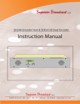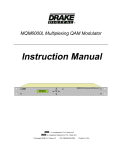
1
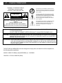
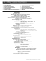
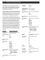
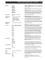
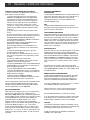
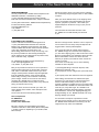
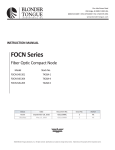
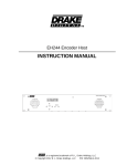
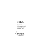
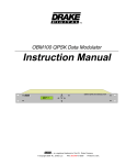
DQT1000 Digital to QAM Transcoder
MQM1000 Multiplexing QAM Modulator
Instruction Manual
TM is a trademark of R.L. Drake LLC
is a registered trademark of R.L. Drake LLC
© Copyright 2007 R.L. Drake LLC
P/N: 3852395C-09-2007
Printed in U.S.A.
2
Caution Statements
WARNING: TO PREVENT FIRE OR
ELECTRICAL SHOCK DO NOT
EXPOSE TO RAIN OR MOISTURE
A product and cart combination should be moved
with care. Quick stops, excessive force and uneven
surfaces may cause the product and cart combination to overturn.
RISK OF ELECTRIC SHOCK
DO NOT OPEN
The lightning flash with arrow head symbol, within
an equilateral triangle, is intended to alert the user
to the presence of uninsulated "dangerous voltage"
within the product's enclosure that may be of
sufficient magnitude to constitute a risk of electric
shock to persons.
CAUTION: TO REDUCE THE RISK OF ELECTRIC
SHOCK,
DO NOT REMOVE COVER
NO USER-SERVICEABLE PARTS INSIDE
REFER SERVICING TO QUALIFIED PERSONNEL
The exclamation point within an equilateral triangle
is intended to alert the user to the presence of
important operating and maintenance (servicing)
instructions in the literature accompanying
the product.
CAUTION
WARNING: TO REDUCE THE RISK OF FIRE OR ELECTRIC SHOCK, DO NOT EXPOSE THIS PRODUCT
TO RAIN OR MOISTURE.
DO NOT OPEN THE CABINET, REFER SERVICING TO QUALIFIED PERSONNEL ONLY.
CAUTION: TO PREVENT ELECTRIC SHOCK, DO NOT USE THIS (POLARIZED) PLUG WITH AN EXTENSION
CORD RECEPTACLE OR OTHER OUTLET UNLESS THE BLADES CAN BE FULLY INSERTED TO
PREVENT BLADE EXPOSURE.
ATTENTION: POUR PREVENIR LES CHOCS ELECTRIQUES, NE PAS UTILISER CETTE FICHE POLARISEE
AVEC UN PROLONGATEUR, UNE PRISE DE COURANT OU UNE AUTRE SORTIE DE COURANT, SAUF SI LES LAMES PEUVENT ETRE INSEREES A FOND SANS EN LAISSER AUCUNE
PARTIE A DECOUVERT.
The DQT1000 and MQM1000 have been designed to comply with, and tested to confirm compliance to,
the following satety regulations:
ANSI/UL 60065, 7th Edition, dated 06/30/2004, rev. 11/20/2006.
CAN/CSA - C22.2 No. 60065:03 (2006).
Important Safety Instructions
1. Read Instructions—All the safety and operating instructions should be read
before the product is operated.
2. Retain Instructions—The safety and operating instructions should be
retained for future reference.
3. Heed Warnings—All warnings on the product and in the operating
instructions should be adhered to.
4. Follow Instructions—All operating and use instructions should be followed.
5. Cleaning—Unplug this product from the wall outlet before cleaning. Do not
use liquid cleaners or aerosol cleansers. Use a damp cloth for cleaning.
6. Attachments—Do not use attachments that are not recommended by the
product manufacturer as they may cause hazards.
7. Water and Moisture—Do not use this product near water—for example,
near a bathtub, wash bowl, kitchen sink or laundry tub; in a wet basement;
or near a swimming pool; and the like.
8. Accessories—Do not place this product on an unstable cart, stand, tripod,
bracket, or table. The product may fall, causing serious injury to a child or adult,
and serious damage to the product. Use only with a cart, stand, tripod, bracket,
or table recommended by the manufacturer, or sold with the product. Any
mounting of the product should follow the manufacturer's instructions, and
should use a mounting accessory recommended by the manufacturer.
9. A product and cart combination should be moved with care. Quick stops,
excessive force, and uneven surfaces may cause the product and cart
combination to overturn.
10. Ventilation—Slots and openings in the cabinet are provided for ventilation
and to ensure reliable operation of the product and to protect it from
overheating, and these openings must not be blocked or covered. The
openings should never be blocked by placing the product on a bed, sofa, rug,
or similar surface. This product should not be placed in a built-in installation
such as bookcase or rack unless proper ventilation is provided or the
manufacturer's instructions have been adhered to.
11. Power Sources—This product should be operated only from the type of
power source indicated on the marking label. If you are not sure of the type of
power supplied to your home, consult your product dealer or local power
company. For products intended to operate from battery power, or other
sources, refer to the operating instructions.
12. Grounding or Polarization—This product may be equipped with a
polarized alternating-current line plug (a plug having one blade wider than the
other). This plug will fit into the power outlet only one way. This is a safety
feature. If you are unable to insert the plug fully into the outlet, try reversing
the plug. If the plug should still fail to fit, contact your electrician to replace
your obsolete outlet. Do not defeat the safety purpose of the polarized plug.
Alternate Warnings—If this product is equipped with a three-wire groundingtype plug, a plug having a third (grounding) pin, the plug will only fit into a
grounding-type power outlet. This is a safety feature. If you are unable to insert
the plug into the outlet, contact your electrician to replace your obsolete outlet.
Do not defeat the safety purpose of the grounding-type plug.
12 a. Mise à la terre ou Polarisation—Cet appareil est équipé avec un cordon
d'alimentation à trois fils. Il est a brancher sur une prise ayant un connecteur
a la terre. Assurez-vous que la connection a la terre ne manque pas.
13. Power-Cord Protection—Power-supply cords should be routed so that
they are not likely to be walked on or pinched by items placed upon or against
them, paying particular attention to cords at plugs, convenience receptacles,
and the point where they exit from the product.
3
14. Outdoor Antenna Grounding—If an outside antenna or cable system is
connected to the product, be sure the antenna or cable system is grounded so
as to provide some protection against voltage surges and built-up static
charges. Article 810 of the National Electrical Code, ANSI/NFPA 70, provides
information with regard to proper grounding of the mast and supporting
structure, grounding of the lead-in wire to an antenna discharge unit, size of
grounding conductors, location of antenna-discharge unit, connection to
grounding electrodes, and requirements for the grounding electrode.
See Figure A.
15. Lightning—For added protection for this product during a lightning storm,
or when it is left unattended and unused for long periods of time, unplug it from
the wall outlet and disconnect the antenna or cable system. This will prevent
damage to the product due to lightning and power-line surges.
16. Power Lines—An outside antenna system should not be located in the
vicinity of overhead power lines, other electric light or power circuits, where it
can fall into such power lines or circuits. When installing an outside antenna
system, extreme care should be taken to keep from touching such power lines
or circuits as contact with them may be fatal.
17. Overloading—Do not overload wall outlets, extension cords, or integral
convenience receptacles as this can result in a risk of fire or electric shock.
18. Object and Liquid Entry—Never push objects of any kind into this product
through openings as they may touch dangerous voltage points or short-out
parts that could result in a fire or electric shock. Never spill liquid of any kind
on the product.
19. Servicing—Do not attempt to service this product yourself as opening
or removing covers may expose you to dangerous voltage or other hazards.
Refer all servicing to qualified service personnel.
20. Damage Requiring Service—Unplug this product from the wall outlet and
refer servicing to qualified service personnel under the following conditions:
a. When the power-supply cord or plug is damaged,
b. If liquid has been spilled, or objects have fallen into the product,
c. If the product has been exposed to rain or water,
d. If the product does not operate normally by following the operating
instructions. Adjust only those controls that are covered by the operating
instructions as an improper adjustment of other controls may result in damage
and will often require extensive work by a qualified technician to restore the
product to its normal operation,
e. If the product has been dropped or damaged in any way, and
f. When the product exhibits a distinct change in performance—this indicates
a need for service.
21. Replacement Parts—When replacement parts are required, be sure the
service technician has used replacement parts specified by the manufacturer
or have the same characteristics as the original part. Unauthorized substitutes
may result in fire, electric shock or other hazards.
22. Safety Check—Upon completion of any service or repairs to this product,
ask the service technician to perform safety checks to determine that the
product is in proper operating condition.
23. Wall or Ceiling Mounting—The product should be mounted to a wall or
ceiling only as recommended by the manufacturer.
24. Heat—The product should be situated away from heat sources such as
radiators, heat registers, stoves, or other products (including amplifiers) that
produce heat.
Figure A
Example of antenna grounding as per National Electrical Code, ANSI/NFPA 70
NOTE TO CATV SYSTEM INSTALLERS:
THIS REMINDER IS PROVIDED TO CALL THE
CATV SYSTEM INSTALLER'S ATTENTION TO
ARTICLE 820 - 40 OF THE NEC THAT
PROVIDES GUIDELINES FOR PROPER
GROUNDING AND, IN PARTICULAR,
SPECIFIES THAT THE CABLE GROUND SHALL
BE CONNECTED TO THE
GROUNDING
SYSTEM OF THE BUILDING, AS CLOSE TO
THE POINT OF CABLE ENTRY AS PRACTICAL.
ANTENNA
LEAD IN
WIRE
GROUND CLAMP
ANTENNA
DISCHARGE UNIT
(NEC SECTION 810-20)
ELECTRIC
SERVICE
EQUIPMENT
GROUNDING CONDUCTORS
(NEC SECTION 810-21)
GROUND CLAMPS
NEC - NATIONAL ELECTRIC CODE
POWER SERVICE GROUNDING
ELECTRODE SYSTEM
(NEC ART 250, PART H)
4
Table of Contents / Specifications
TABLE OF CONTENTS
2
3
4
5
6
Caution Statements
Important Safety Instructions
Table of Contents / Specifications
General Description
Installation and Mounting / Front Panel Controls
7
8
12
13
14
Rear Panel Controls and Connections
Setup and Programming
Operation / Additional Features
Service / If You Need To Call For Help
Warranty
SPECIFICATIONS
DEMODULATOR (S)
DQT1000 ONLY:
Input Frequency Range:
Channel Plans (Menu selectable):
Input Channel Bandwidth:
Input RF Level Range:
Minimum Input Level per Mode:
Maximum Input Power (sum of all channels):
Input Impedance:
Image rejection:
Adjacent Channel Rejection:
Noise Figure:
Demodulation Modes:
Symbol Rates:
Equalizer Span:
Not present - MQM1000
54 to 864 MHz.
Std. CATV, HRC, IRC, or Broadcast
6 MHz.
-28 dBmV to +30 dBmV
8VSB: -28dBmV, 16VSB: -25dBmV,
64QAM: -20dBmV, 256QAM: -15 dBmV.
Not to exceed -16 dBm.
75 Ohms with Return Loss typically 8 dB.
40 dB.
60 dB
Less than 12 dB.
8VSB,16VSB - ATSC
16QAM, 32QAM, 64QAM, 128QAM, or 256QAM - ITUA
64QAM, 256QAM, - ITUB
Commonly used presets and user programmable.
-6 µS to +40 µS.
ASI INPUTS
MQM1000-Two Inputs 270 Mbps with desired transport stream of
DQT1000 ASI Option: 10.76 MS/s, ATSC, 19.37 Mbps
NULL PACKET PROCESSING: DQT1000 and MQM1000 (fixed output clock mode)
QAM MODULATOR
Modulation Modes: 16QAM, 32QAM, 64QAM, 128QAM, 256QAM, 512QAM or
1024QAM. (See page 9 for all available combinations of QAM
modes and FEC.)
Symbol Rate: 1 Ms/s to 7 Ms/s.
FEC: ITUA (DVB) or ITUB (DigiCipher II).
I/Q Phase Error: Less than 1 degree.
Carrier Suppression: 45 dB.
Channel Amplitude Error: Less than 1 dB.
MER: Greater than 38 dB with blind equalizer.
ANALOG EAS IF INPUT
Operating Input Level: +30 dBmV ±5 dB at 45.75 MHz, 75 Ohms
Auto Switching Level: + 20 dBmV minimum.
UPCONVERTER RF OUTPUT
Output Frequency Range:
Channel Plan:
FCC offsets:
Frequency Stability:
Maximum Output Level:
Minimum Output Level:
Output Level Accuracy:
Output Impedance:
54 MHz to 1002 MHz.
Std. CATV, HRC, IRC, or Broadcast
Automatic, +12.5 or +25 kHz
± 5 ppm.
+ 61 dBmV minimum, adjustable downward.
+ 45 dBmV.
± 1 dB.
75 Ohms with return loss better than 14 dB
(within output filter passband).
Spurious Outputs: -60 dBc from 40 MHz to 1000 MHz.
Broadband Noise: Less than -12 dBmV (6 MHz BW @ ±12 MHz).
Phase Noise: -101 dBc @ 10 kHz offset
RS232 CONTROL
Data Link: 2400, 4800, 9600, or 19,200 baud interface via serial cable.
RS232 Input: DB-9 connector for connection to modem or PC.
RS232 Output: DB-9 connector for connection to addtional transcoders.
GENERAL
Power:
Weight:
Size:
Operating Temperature:
90 - 132 VAC/ 60 Hz, 40 W maximum.
7 pounds
19” W x 1.75” H x 11.5” D.
0 degrees C to + 50 degrees C
Specifications subject to change without notice or obligation.
General Description
5
MQM1000 Multiplexing QAM Modulator
ASI A
26.88dB
ASI B
24.52dB
ENTER
GENERAL DESCRIPTION
The R.L. Drake model DQT1000 is a professional quality,
digital headend transcoder that receives one or two ATSC,
or ATSC compatible MPEG2, 8VSB or QAM signals from
an off air antenna or from a CATV source. It demodulates
the signals to recover the MPEG2 transport stream(s),
multiplexes the MPEG2 transport streams from DEMOD A
and either the second RF input (DEMOD B) or the ASI
input if used, and modulates the resulting combined
stream using QAM modulation followed by a built in
upconverter for output to a CATV system.
The model MQM1000 does not contain a RF demodulator
but instead accepts one or two ATSC multiprogram
transport streams via two BNC, ASI inputs. When two
streams are input, the MQM1000 then multiplexes the two
ATSC streams in the same manner as the DQT1000.
The DQT1000 and MQM1000 provide essentially the
same function as the popular DQT860 and MQM860 units.
In addition, the '861' and '1000' models provide a program
filter function (a new Select Program menu) and offer
improved upconverter specs with phase noise reduced to
a level that is compatible with QAM modes up though
1024QAM.
The '1000' models provide the same features as the '861'
models except that the upconverter has been upgraded to
allow operation up to 1000 MHz on the output side. The
new '1000' models can be used with the Drake Digital
Headend Remote Control Software, version 2.6 or later,
for remote controlling or remote monitoring of operating
parameters. This program can also be used to download
new firmware into the unit if that ever becomes desirable.
The DQT1000 and MQM1000 operate in a fixed output
clock mode and process null packets when required to
maintain the set fixed clock rate. PCR correction is
included.
DIGITAL CHANNEL PROCESSING
The single input DQT1000, available by special order, is
ideal for digital 'channel processing' applications where a
single digital video signal is received, error corrected,
clocked at a user determined fixed rate and remodulated
on the same or another RF channel. Applications include
cleaning up a low MER QAM signal received from a CATV
source or fiber link receiver, or shifting the RF frequency of
a QAM modulated signal. It may be used to convert one
off-air ATSC 8VSB signal to a QAM output with rate
adjustment. Used in the processor mode with only one
input, the DQT1000 can process ATSC, DVB, or DigiCipher
II compliant MPEG2 inputs that are either VSB or QAM
modulated. No multiplexing or altering of any MPEG
tables is performed in this mode.
Used in the non multiplexing mode, the data rate of the
incoming signal can be any rate that falls within the
specification range. The output rate can be set to any fixed
output rate (equal to or faster than the input rate).
MULTIPLEXING TWO ATSC TRANSPORT STREAMS
With the second RF input/tuner/demodulator (Demod B),
the DQT1000 can accept two 19.4 Mbps ATSC signals
(either with 8VSB modulation or QAM modulation) and
multiplex the transport streams to obtain a 38.8 Mbps
256QAM output. Thus two ATSC inputs can be output on a
single 6 MHz bandwidth 256 QAM channel.
Another way of combining two ATSC 19.4 Mbps streams is
to receive the first stream using the 8VSB input (Demod A)
and input the second stream, if available in ASI format, to
the optional ASI input on The DQT1000. Again the two
combined ATSC signals will be modulated at 256QAM in a
6 MHz wide channel.
If it is desired to provide both ATSC signals from ASI
sources, the model MQM1000 can be used.
When the DQT1000 or MQM1000 multiplexes two ATSC
inputs to produce a 38.8 Mbps output, no loss of picture or
sound packets occurs. There is no added compression
of the video or audio streams. Only the necessary control
packets are rewritten to prevent duplication of MPEG2
program numbers and major and minor channel number
assignments in the tables.
PROGRAM FILTERING
A 'Select Program' function is provided to allow the
operator to select which of the MPEG programs present
on the A and B input streams are to be included in the
output multiplex.
PSIP OPTIONS
When operating in the multiplex mode, the DQT1000 or
MQM1000 can be set to process PSIP information from
both sources and rewrite tables containing combined
PSIP information, or in cases where the off-air broadcast
channels may not be transmitting some or all of the
tables, it can be set to ignore and discard the PSIP tables
completely, or it can be set to generate MGT and VCT
tables without EIT tables. Null packet processing is
applied as necessary to keep the output data rate at the
desired setting. PCR correction is performed when
necessary.
OUTPUT
The RF output is always QAM regardless of whether the
input is VSB or QAM and the built-in agile upconverter
provides 61 dBmV output.
6
Installation & Mounting / Front Panel Controls
INSTALLATION AND MOUNTING NOTES
This equipment is designed to be installed in a standard 19” rack. All models have a built in fan to provide air
movement through the unit. When the unit is mounted above or below other rack mounted equipment, a 1U space
should be left between the unit and the other equipment to allow ambient air flow between the units.
When connecting an incoming RF signal source to the DQT1000 DEMOD A and DEMOD B (if installed) inputs,
note that the antenna or CATV source must be connected to both the DEMOD A and DEMOD B input connectors.
These inputs are kept separate in case the inputs need to come from different antennas or one antenna and one
CATV source. Connect the AC line cord to an appropriate source of 120 volt, 50/60 Hz AC power. The DQT1000
is always on once the AC power cord is connected to its power source.
F1
F2
F5
F6
MQM1000 Multiplexing QAM Modulator
ASI A
26.88dB
ENTER
ASI B
24.52dB
F3
F1, LCD Display – This display presents the selected
menu screen and the parameter settings. The backlight in
the display is on when power is applied.
During operation, the S/N (signal to noise ratios) of the
demodulator input signals are displayed. For 8VSB
inputs, the threshold is about 15 dB. For QAM inputs, the
threshold is about 23 dB for 64QAM and 27 dB for
256QAM. You should maintain a S/N several dB above
these thresholds for reliable operation.
F2, ENTER button – Use the ENTER button to enter the
adjust mode or to save and load a new setting or settings
after adjustment. Hold for 2 seconds until the bottom line
of the display starts to flash to enter the adjust mode. After
entering the adjust mode, momentarily pressing the
ENTER button again will load and save any settings that
may have been changed using the F5 & F6 buttons.
F3 & F4,
Left and
Right Buttons – Use the left and
right arrow buttons to navigate from screen to screen to
F4
view a parameter setting. These buttons are operational in
the view mode or the adjust mode. Using only these
buttons will not change any parameter settings. After a
short period of button inactivity, the default display will
be returned.
F5 & F6,
Up and
Down Buttons – Use the down and
up arrow buttons to change the value of a viewed parameter setting. The unit must be in the adjust mode with the
display flashing in order for these buttons to become
active for changing a parameter setting. If the unit is not in
the adjust mode, pressing the up button will display the
firmware version number or pressing the down button will
display the output QAM symbol rate.
NOTE: The DQT1000 is shown but the MQM1000 has
essentially the same front panel functionality except that
certain menus will not be available for navigation.
Rear Panel Connections
R1
RF OUTPUT
R2
EAS IN
R3
DEMOD A
IN
R4
DEMOD B
IN
R5
R6
7
R7
RS232 IN
ASI INPUT
R9
AC POWER
120 VAC 60 Hz
30 WATTS
RS232 OUT
R8
DQT1000 - shown above
MQM1000 - same as DQT1000 except that the MQM1000
does not have the R3 and R4 demodulator inputs or the
ASI optional input. Instead it has two standard ASI inputs
in place of the RF inputs on the DQT1000. The ASI inputs
are type BNC female connectors. These inputs are used
to input the ATSC transport streams in ASI format instead
of RF.
R1, RF OUTPUT – This is the high level (61 dBmV), 54 to
1002 MHz, output from the DQT1000 upconverter section.
R2, EAS IN – This input may be used to input an alternate
program, usually for emergency alert system requirements.
This is a 44 MHz IF input and the operating level is
+30 dBmV. An auto sensing switch is built in and will
switch the IF to this input whenever the RF level at this jack
exceeds approximately +20 dBmV at 44 MHz. The input
signal can be either analog or digital. When this input is
activated, the demodulators and ASI inputs are essentially
switched off as the output will be determined by the IF
signal input through this jack.
R3, DEMOD A IN - DQT only - 54 to 864 MHz input for
DEMOD A. From an off-air antenna or CATV system.
R3, ASI INPUT A - MQM only.
R4, DEMOD B IN - DQT ONLY - 54 to 864 MHz input for
DEMOD B, if installed. From an off-air antenna or CATV
system.
R4, ASI INPUT B - MQM only.
R5, ASI INPUT - DQT only - Optional DVB ASI format
MPEG2 transport stream input. If installed, an ATSC
stream from this input may be multiplexed with the stream
from DEMOD A.
,
R6, FAN – This cooling fan pulls air through the unit for
cooling. If this fan fails or is blocked the unit may become
warm enough to cause the OVER TEMP alert to be
activated. If the fan has failed, it should be replaced as
soon as possible. Operation with an over temperature
condition present for an extended period of time will lead
to premature component failure even though the unit may
be functioning normally when the condition is first noted.
R7, RS232 IN - Connection to a PC or modem for use with
remote control / monitoring program or for firmload
download.
R8, RS232 OUT - Loop to another DQT or MQM.
R9, AC Line Cord – For connection to the nominal
120 VAC power source. This unit is designed for use in
countries with 120 VAC power standards but the power
supply will accept an input voltage range of 90 VAC
minimum to 260 VAC maximum with a power line
frequency of either 50 or 60 Hz.
8
Setup and Programming
Programming and viewing of the various setup and
operating parameters is accomplished using the front panel
back lit, two line, sixteen character wide LCD along with
the 4 arrow buttons and the ENTER button. The name of
the parameter is on the top line of the display and the
setting value is on the bottom line.
To observe a certain parameter setting without intending to
change its value, just use the left and right arrow buttons to
navigate through the menus shown in the list. The current
setting for each parameter is shown on the bottom line of
the display. Note that depending upon certain settings,
some screens are not needed and will be skipped.
To make a change in the displayed parameter and its
setting and if this is the initial setup, you will want to enter
the ‘adjust’ mode. To do this, press the ENTER button that
is located in the center of the four arrow buttons and hold
in for several seconds until the display begins to flash.
After you are in the adjust mode (bottom line of screen
flashing) use the left and right arrows to navigate among
screens and use the up and down arrows to change the
parameter setting. When ENTER is pressed, the new
settings will be loaded and stored and the unit will exit the
‘adjust’ mode. You may wish to not press ENTER until you
have gone through all screens and settings and then
press ENTER to save and load all changes in one step
OR you can store just one or several parameters at a time
and reenter adjust mode to set the next. Either method is
acceptable.
Menu Item
Top display line.
Use left/right arrows
to navigate.
Parameter Setting Choices
Second display line.
Must be in adjust mode to change
using up/down arrows.
Demod A ChanMap: CATV
DQT
IRC
HRC
Broadcast
Demod A Channel:
DQT
#
Demod A Mode:
DQT
VSB-8
VSB-16
QAM-16A
QAM-32A
QAM-64A
QAM-128A
QAM-256A
QAM-64B
QAM-256B
Demod A SymRate: Preset ( If Preset, Sym Rate is...
DQT
5.381119 for VSB modes
5.000000 for all QAM-A
5.056841 for QAM-64B
5.360537 for QAM-256B)
Manual
Demod A SymRate: x.xxxxxx (Only if Manual)
DQT
MULTIPLEX:
DQT, MQM
Disabled
Demod B
ASI
MPEG PROGRAMS:
(MULTIPLEX is not
disabled)
Select All Programs
Select Programs
(See details on pages 9 & 10)
Demod B ChanMap: CATV (Only if Demod B Enabled)
DQT
IRC
HRC
Broadcast
Demod B Channel:
DQT
# (Only if Demod B Enabled)
Demod B Mode:
DQT
VSB-8 (Only of Demod B Enabled)
VSB-16
QAM-16A
QAM-32A
QAM-64A
QAM-128A
QAM-256A
QAM-64B
QAM-256B
Demod B SymRate: Preset (Only if Demod B Enabled)
DQT
(If Preset, Sym Rate is...
5.381119 for VSB modes
5.000000 for all QAM-A
5.056841 for QAM-64B
5.360537 for QAM-256B)
Manual
SymRate:
DQT
x.xxxxxx (Only of Demod B Enabled)
(Only if Manual)
Input B Offset:
DQT, MQM
0 (Only if Multiplex Enabled)
10
20
30
40
50
60
70
80
90
PSIP:
DQT, MQM
Enabled
Disabled
Basic MGT & VCT
VCT TABLE:
DQT, MQM
TVCT (Only if Multiplex Enabled)
CVCT
Major Channel:
DQT, MQM
Original (Only if Multiplex Enabled)
RF Channel
Setup and Programming, continued
QAM Mode:
QAM-16A
QAM-32A
QAM-64A
QAM-128A
QAM-256A
QAM-512A
QAM-1024A
QAM-64B
QAM-256B
QAM-1024B
Gray Encoding:
DVB (Only if ITU-A selected)
DAVIC
QAM Sym Rate:
DQT, MQM
Preset (If Preset, Sym Rate is...
5.0000 for all ITU-A,
5.0570 for QAM-64B
5.3606 for QAM-256B
5.3606 for QAM-1024B)
Manual
QAM Sym Rate:
DQT, MQM
x.xxxx M Sym/Sec (Only if Manual)
Interleaver:
I128,J1 (Only if ITU-B selected...
I128,J2 fixed at I12,J17 if ITU-A)
I64,J2
I128,J3
I32,J4
I128,J4
I16,J8
I128,J5
I8,J16
I128,J6
I4,J32
I128,J7
I2,J64
I128,J8
I1,J128
Output Format:
Output ChanMap:
Normal
CW
STANDBY
PRBS 15
PRBS 15M
PRBS 23
PRBS 23M
CATV
IRC
HRC
Broadcast
OUTPUT CHANNEL:
#
RF OUT:
xx.x dBmV (45.0 to 62.0 dBmV)
UNIT ID:
# (0 thru 63)
RS232 Baud Rate:
2400
4800
9600
19,200
9
DEMOD A CHANMAP: Select the setting corresponding to
source of the input to DEMOD A. Choices are BROADCAST,
CATV, IRC, HRC.
DEMOD A CHANNEL: Select the desired channel number.
DEMOD A MODE: Select the modulation type of DEMOD A
input signal. Choices are VSB-8, VSB-16, QAM-256B, QAM64B, QAM-256A, QAM-128A, QAM-64A, QAM-32A, QAM16A.
Off air broadcast signals will be VSB-8. In the QAM
choices, the B suffix is DigiCipher II (used by most major
MSOs) and the A suffix is DVB.
DEMOD A SYMRATE: This is the symbol rate or baud rate of
the desired input signal on the DEMOD A input. The
choices are PRESET or MANUAL. If PRESET is selected, the
most commonly used rates are set and can be viewed in the
screen following this screen after exiting the ‘adjust’
mode. If MANUAL is selected, use the right arrow to go on
to the continuation of this screen and then use the up and
down arrows to set the desired symbol rate. Use PRESET
for off-air VSB-8, signals.
MULTIPLEX: This setting determines whether the DEMOD
A input is to be multiplexed with a second input (if installed). Select DEMOD B to activate the B channel
demodulator and to turn on the multiplex function. Select
ASI if the second input is present at the ASI input connector
and it is desired to multiplex this ASI input stream with the
stream from DEMOD A. DEMOD B (if also installed) will be
turned off in the ASI setting. When DEMOD B is chosen,
any data at the ASI input is ignored. If the DQT1000 is
being used as a processor of only one input at DEMOD A,
select DISABLED. If DISABLED is selected, the next menu
will be the QAM MODE menu, you may skip to that paragraph, below.
MPEG PROGRAMS: This menu provides selections to
determine which programs are multiplexed to form the
new multiprogram transport stream output that will be
supplied to the QAM modulator section. Choose the
SELECT ALL PROGS setting to multiplex all programs
from inputs A and B.
It is the operator's responsibility to be sure that the total
data rate of these programs does not exceed the maximum data rate for the output QAM mode that will be used.
If the total input rate is too large, some programs will have
to be dropped from the multiplex.
Choose the SELECT PROGRAMS setting to allow the
operator to pick which programs from the A and B inputs
are to be included in the output multiplex.
NOTE: At this point you may proceed through the remaining menus, below, before pressing the ENTER button to
load the selected data OR you may press ENTER now and
then come back to the rest of the menus. In any case,
when the ENTER button is pressed, one of the following
two actions will occur:
A) If SELECT ALL PROGS has been selected, the
DQT1000 will now read PAT tables from the two input
streams and
10
Setup and Programming, continued
find out which MPEG programs are defined. If you wish to
view the MPEG program numbers of programs that were
found, follow the procedure below:
VIEWING MPEG PROGRAM NUMBERS
In order to see the MPEG program numbers of incoming
streams, the following procedure can be followed:
1) Press the ENTER button for 2 seconds to enter program
mode. Release button. Display will be flashing.
2) Press the ENTER key again and hold. By continuing to
hold in the ENTER button, the following display will be
slowed down so that program numbers can be read as
they scroll by.
3) A screen will be displayed that indicates:
PMT PROG A xxxx or PMT PROG B xxxx.
4) The xxxx field will be a number that corresponds to the
MPEG program number of a program found in the PMT
table for the indicated (A or B) input. As the button is held,
all entries for input A will scroll past and then entries for
input B will scroll past.
5) Release button and if necessary repeat steps 1 - 4.
B) If SELECT PROGRAMS was chosen, the unit will read
the PAT tables from both inputs and then display:
MPEG PROG XXXXX: (XXXXX is a number from 00001 to
65535) on the top line of the display. Using the right and
left arrow keys, you can scroll through all 65535 possible
program numbers.
Don't be alarmed by the large number of possibilities
because if the arrow key is held down, the scrolling will
speed up so all 65535 possible numbers can be scanned
in a short time - any time an entry is found at a given
program number, the scrolling will slow down to give the
operator time to see it and stop scrolling, if desired.
Usually, all programs are known to be numbered between
01 and 20.
For each MPEG program number, displayed on the top
line, the bottom line, on the right, will indicate A, B, AB, or
nothing. This will indicate that the program number on the
top line was found in input A or B or AB for both or not in
either one if blank.
To select programs to be included in the output multiplex,
use the up and down arrow keys to select NOT SELECTED, INPUT A, INPUT B, or INPUT A+B. If NOT
SELECTED is used, then this program number will not be
present in the output and any programs with this program
number that are present in the A or B inputs will be filtered
out. If INPUT A is selected, the A input program only is
used. If INPUT B is selected, the B program is used and A
filtered out. If INPUT A+B is chosen, then both are accepted if present.
Note: It is OK to use this menu to set up desired program
selections 'off line'. That is, with no actual input at the
present time. Programs may be selected that may not
currently be in the input stream but are desired at some
future time.
Note: It is possible to select both programs with the same
program number - one from A and one from B as long as
the INPUT B offset is set so that the B program number
plus the offset amount does not duplicate a program
number from the A input. The offset is not included in the
MPEG program number display being discussed above
but the offset will be added to all MPEG program numbers
from the B input when they are added to the output
multiplex.
DEMOD B CHANMAP, DEMOD B CHANNEL, DEMOD B
MODE, DEMOD B SYMRATE:
See descriptions for DEMOD A above. These are equivalent settings for the DEMOD B demodulator input, when
installed.
INPUT B OFFSET: When the DEMOD B or ASI input has
been installed and selected in the MULTIPLEX menu, this
menu will be present. Because the two incoming transport
streams are likely to have overlapping use of MPEG
program numbers, the DQT861 or MQM861 will pass the
program numbers from input A unchanged and an offset,
equal to the value chosen in this menu, will be added to
the program number of programs from the second input.
This same offset value will also be added to the minor
channel number in the VCT table for programs from the
second input source. Usually an offset of 10 will be
adequate but if you know there are programs in the signal
input to input A using program numbers above 10, a higher
offset may be required. Values between and 10 and 90, in
increments of 10, are available for selection. When it is
known that there is no overlap between input A and input B
stream program numbers, a 0 offset setting can be used.
Be cautious if this is the selection that is chosen.
PSIP: This menu provides a choice of how the unit
organizes the PSIP information from two ATSC streams
that are being multiplexed.
In the ENABLED setting, information from the MGT and
VCT tables from both signals will be used to build a new
table for the combined output signal. Both input streams
must have these tables present in order for the unit to be
able to perform this operation. EIT tables will be processed so as to provide program information, if present,
for the next 12 hours. This selection is the only one that
passes EIT table program information to the multiplexed
output signal. RRT and STT tables from Demod A are
passed through.
If the broadcast station is not transmitting complete MGT
and VCT tables, the ENABLED selection cannot be used.
In this situation, DISABLED may be selected. In DISABLED
mode, the unit does not process or output any MGT, VCT,
or EIT tables. This can be a fine solution for cable systems
that use set top boxes which operate from their own
system channel map and have no need for these tables.
MPEG program information is still processed. Some retail
consumer QAM set tops operate perfectly in this mode and
others may not.
Setup and Programming, continued
The third option is the BASIC MGT, VCT choice. When this
selection is made, the DQT1000 or MQM1000 will build its
own MGT and VCT tables from the incoming streams even
if one or both of the streams do not contain these tables.
This solution should satisfy all types of set top boxes but
will not provide any EIT table program guide information.
The STT and RRT tables from the source are passed
through unchanged in the ENABLED mode and filtered out
in the other modes.
VCT TABLE: This menu is only available when ENABLED
or BASIC MGT, VCT has been selected in the previous
PSIP menu. You may select the TVCT - TV channel table or
CVCT table for CATV. Usually the TVCT choice must be
selected for ATSC input signals.
MAJOR CHANNEL: This menu is not available if PSIP is
disabled. When ORIGINAL is selected, the major channel
number indicated in the output tables will be that sent by
the original broadcaster. If OUTPUT CHANNEL is selected,
the major channel number will be set to the channel
number of the DQT1000 RF output channel. This setting
will determine how a channel number is displayed on a
consumer TV if the TV is tuning the output of the DQT1000
without a cable box. When a cable box is used, it usually
does not require or use this information.
QAM MODE: This menu allows the user to set the modulation type for the output. Choices range from 16-QAM
through 256-QAM. A suffixes indicate DVB compliant FEC
and the B suffixes indicate DigiCipher II FEC encoding.
Note that when using the DQT1000 or MQM1000 in the
multiplex mode, the output QAM mode usually must be
256-QAM. For CATV systems using DigiCipher II, select the
QAM-256B mode. For DISH Network QAM distribution or
other DVB systems using DVB set tops, choose the QAM256A mode.
When used for a single input processing function, choose
the output mode accordingly from any of the available
options that will provide a high enough data rate.
QAM SYMRATE: This menu allows selection of the output
QAM baudrate or symbol rate. Set as required by the set
top box. When multiplexing two ATSC input signals, in
DigiCipher II, 256-QAM CATV systems, this is usually
5.3606 Ms/s. In DVB systems, the rate would be 5.264
Ms/s. In any case, the rate must be high enough to provide
11
a data bitrate of at least 38.81 Mbps (do not confuse this
with the symbol rate). If the set top box requires a fixed
higher rate, this may be manually set.
INTERLEAVER: Sets the QAM modulator interleaver.
Choose among the available selections based upon your
system / set top box requirements. For typical 256-QAM.
DigiCipher II CATV systems, I128, J1 is the most commonly used interleave setting but many other choices are
available. This menu does not appear in the adjust mode if
the QAM mode is A (DVB) as there is only one choice in the
DVB standard. When not in adjust mode, this screen will
display the setting in QAM - A modes as well.
OUTPUT FORMAT: For normal operation, select NORMAL.
For system level set up, choose CW to provide a CW
carrier at the center frequency of the output channel for use
in leveling a system when a QAM power meter is not
available. To disable all RF output, select STANDBY. In the
CW mode, the CW carrier can be measured on a spectrum
analyzer without a need to apply a bandwidth correction or
it can be measured with an analog meter tuned to channel
center. The CW power measured will equal the channel
QAM power when the modulator is returned to NORMAL
output mode. Usually QAM signals are set 5 dB to 10 dB
below analog NTSC channels when balancing a system.
The PRBS modes provide a pseudo random binary
sequence output test signal for use in laboratory testing.
OUTPUT CHANMAP, OUTPUT CHANNEL: Select the desired
EIA CATV channel output using these two menus.
RF OUT: Select the desired RF output signal level. The
available range is between 45 dBmV and 62 dBmV,
selectable in 0.5 dB steps. The output accuracy is ± 1 dB.
UNIT ID: Select the desired unit identification number when
connecting the 'RS232 IN' connector to a PC or modem for
remote control using Drake Remote Control Software.
Numbers 1 thru 63 may be used. If zero (0) is selected,
the PC will ignore the unit.
RS232 BAUD RATE: This setting determines the baud rate
at which the DQT1000 or MQM1000 communicates with
the remote PC. Settings available are 2400, 4800, 9600
and 19,200. All unit 'daisy chained' to the remote PC or
modem must be set to the same baud rate.
12
Operation / Additional Information
OPERATION - MULTIPLEXING TWO ATSC INPUTS
To use the DQT1000 or the MQM1000 to multiplex two
ATSC inputs, proceed as follows:
1) Connect the off-air antenna or CATV feed to the
DEMOD A and DEMOD B inputs of the DQT1000 or
connect the two ASI inputs to the MQM1000. For the
DQT1000 the two input connectors are separate in
case the two RF signals must come from different
antennas or if one signal is coming from a cable
system, etc. If using a common antenna, use a good
quality two way splitter to split the antenna and feed
each input.
2) Plug the power cord from the unit into the power
source.
3) Follow the instructions in the programming section
above to set the channel map and channel number for
both DEMOD A and DEMOD B - DQT1000 only.
4) Set the DEMOD SYMRATE to PRESET for both the A
and B channel - DQT1000 only.
5) Set the MULTIPLEX setting to DEMOD B for the
DQT1000 or to ASI for the MQM1000
6) Set the MUX OFFSET to 10. Read details in programming section to determine if you need another
value.
7) Select the desired MPEG programs. (See the
previous section for details.)
8) In the PSIP menu, select BASIC MGT VCT for now,
this may be changed later. See programming section
for detail.
9) In the VCT TABLE menu, select TVCT.
10) In the MAJOR CHANNEL menu, select OUTPUT
CHANNEL. This may be changed later.
11) From the QAM MODE menu, set the QAM modulator
to QAM-256B for use in a DigiCipher II environment. If
DVB, use QAM-256A instead.
12) In the QAM SYMRATE menu, select PRESET.
13) Set the INTERLEAVER to I128,J1 if in a DigiCipher
II environment. There is no interleaver menu when the
QAM mode is set to A (DVB).
14) Set the OUTPUT FORMAT to NORMAL.
15) Set the OUTPUT CHANMAP and OUTPUT CHANNEL to the desired EIA CATV output channel.
If the second program is being input to a DQT1000 via the
ASI input instead of DEMOD B, the same steps apply
except that the MULTIPLEX setting will be ASI and there
will be no parameters to set for DEMOD B.
SET TOP BOX MAPPING
When setting up a program map for your set top boxes to
include off-air channels that are multiplexed by the
DQT1000 or MQM1000 be sure to inform the programmer
that the MPEG program numbers for the programs coming
in through DEMOD B or ASI B have been offset by the
amount selected in the MUX OFFSET menu. As an
example: If input A is providing a channel with MPEG
programs 1 and 2 in the stream and input B is providing a
channel with MPEG programs 1, 2, 3, 4, and 5 in the
stream, and the MUX OFFSET is set to 10, then the new
output signal will contain MPEG programs with program
numbers of 1, 2, 11, 12, 13, 14, and 15. If the set top is not
looking for the right program number, you will not receive
any video!
ADDITIONAL INFORMATION
STANDBY MODE
The DQT1000 and MQM1000 have a standby output mode
which turns off the RF output. This can be used when it is
desirable to temporarily disable the output without
unplugging the AC line cord. Select STANDBY in the
OUTPUT FORMAT menu.
EAS
The DQT1000 and MQM1000 provide an IF input for
Emergency Alert System applications. See R2 in the rear
panel connections descriptions.
OVER TEMPERATURE SENSOR
Temperature monitoring is built into these products. If the
ventilation holes or fan output opening are blocked or the
fan should stop, overheating can occur. If this condition is
detected, the default LCD message will change to OVER
TEMP. If this occurs, the problem should be corrected as
soon as possible. The unit will remain operational but the
ventilation must be restored to prevent premature part
failures due to overheating.
STATUS DISPLAYS
When the units are not in the adjust/program mode, status
displays are shown. These vary by model: DQT1000 shows DEMOD A and DEMOD B SNRs. MQM1000 shows
ASI A and ASI B data presence. QQP860 - shows demod
SNR and ERRORS. The ERRORS display is a five digit
number that shows the number of correctable errors that
were processed in a 4.5 second window. A low number is
best.
Pushing the UP arrow button will cause the firmware
version number to display. Pressing the DOWN arrow will
cause QAMSYMRATE to display - the output symbol rate of
the QAM modulator.
REMOTE CONTROL AND MONITORING
The DQT1000 or MQM1000 may be used with the 'Drake
Digital Headend Remote Control Software' program to
allow remote monitoring or control. Only version 2.6 or
newer are compatible with the DQT1000 or MQM1000.
Connect the RS232 cable coming from the PC or modem
to the RS232 IN DB9 rear panel connector.
Assign a UNIT ID (1 to 63) to use the remote program.
Leave at, or set to, 0 if no remote access is desired.
Set the RS232 BAUD RATE to match the PC setting.
If you are familiar with the program, operation will be clear.
If not familiar with it, see further instructions in the insert
provided with the CDROM or stored on the CDROM.
OPTIONS
A second RF demodulator module, PN 1002369, may be
added by the Drake service department to a DQT1000 that
was initially purchased with only one RF input.
A DVB ASI input board, PN 1002368, is available for
installation into a DQT1000.
Service / If You Need To Call For Help
SERVICE INFORMATION
You may contact the R.L. DRAKE Service Department for
additional information or assistance by calling
+1 (937) 746-6990, Monday through Friday, between
8:00 A.M. and 4:00 P.M. Eastern Time, except on holidays.
You may also contact the R.L. DRAKE Service Department by
E-mail at the following address:
[email protected]
or by Telefax:
+1 (937) 806-1576.
IF YOU NEED TO CALL FOR HELP
Call our Customer Service/Technical Support line at
+1 (937) 746-6990 between 8:00 A.M. and 4:00 P.M.
Eastern Time, weekdays. Please have the unit’s serial
number available. We will also need to know the specifics
of any other equipment connected to the unit.
When calling, please have the unit up and running, near
the phone if possible. Our technician(s) will likely ask
certain questions to aid in diagnosis of the problem. Also,
have a voltmeter handy, if possible.
R.L. DRAKE also provides technical assistance by
e-mail: [email protected]
or by Telefax: +1 (937) 806-1576.
Many of the products that are sent to us for repair are in
perfect working order when we receive them. For these
units, there is a standard checkout fee that you will be
charged. Please perform whatever steps are applicable
from the installation sections of the Owner's Manual
before calling or writing—this could save unnecessary
phone charges. Please do not return the unit without
contacting R.L. DRAKE first: it is preferred to help
troubleshoot the problem over the phone (or by mail) first,
saving you both time and money.
Inside the carton, enclose a note with your name, address, daytime phone number, and a description of the
unit’s problem.
The unit must be sent to the following address:
Service Department
R.L. DRAKE LLC
230 Industrial Drive
Franklin, Ohio 45005 U.S.A.
Be sure to include your street address which will be
needed for UPS return. UPS Surface (Brown Label) takes
7-10 days to reach us depending on your location, Blue
takes 2-3 days.
13
Should you want to return your unit for service, package
the unit carefully using the original carton or other suitable
container.
Write your return address clearly on the shipping carton
and on an enclosed cover letter describing the service
required, symptoms or problems. Also include your
daytime telephone number and a copy of your proof of
purchase.
The unit will be serviced under the terms of the
R.L. DRAKE LLC Limited Warranty and returned
to you.
Red is an overnight service. Send the unit in a way that it
can be traced if we can’t verify receipt of shipment. We
suggest UPS or insured postal shipment.
If the unit is still under the original owner’s warranty,
R.L. DRAKE will pay the cost of the return shipment to
you. Our return shipping policy is that we will return it UPS
Brown if received Brown or by US Mail, it will be returned
Blue if received Blue or Red—or it will be returned
however you prefer if you furnish the return cost for the
method you select.
If the unit is out of warranty, use one of the following
methods for return shipment:
1) You designate billing to American Express, VISA,
MasterCard or Discover card;
2) You prepay the service charges with a personal check,
or
3) You specify some other method of return and payment.
When calling, the technician can estimate the repair
charges for you over the phone. This is another good
reason to call before sending a unit in for repair.
Typically, equipment is repaired in five to ten working days
after it arrives at R.L. DRAKE if we have all the facts. If we
must call you, it may take longer. R.L. DRAKE is not
responsible for damage caused by lightning, nonprofessional alterations, “acts of God”, shipping damage, poor
storage/handling, etc. R.L. DRAKE will make note of any
shipping damage upon receipt.
You will need to send proof of purchase to receive
warranty service. Typically, a copy of the invoice from an
R.L. DRAKE dealer will suffice. The warranty is for the
original owner only and is not transferable.
14 Warranty
Three Year Limited Warranty
R.L. DRAKE LLC warrants to the original purchaser this product shall be free from defects in material or workmanship
for three (3) years from the date of original purchase.
During the warranty period the R.L. DRAKE LLC or an authorized Drake service facility will provide, free of charge, both
parts and labor necessary to correct defects in material and workmanship. At its option,
R.L. DRAKE LLC may replace a defective unit.
To obtain such a warranty service, the original purchaser must:
(1) Retain invoice or original proof of purchase to establish the start of the warranty period.
(2) Notify the R.L. DRAKE LLC or the nearest authorized service facility, as soon as possible after discovery of a possible
defect, of:
(a) the model and serial number,
(b) the identity of the seller and the approximate date of purchase; and
(c) A detailed description of the problem, including details on the electrical connection to associated equipment and
the list of such equipment.
(3) Deliver the product to the R.L. DRAKE LLC or the nearest authorized service facility, or ship the same in its original
container or equivalent, fully insured and shipping charges prepaid.
Correct maintenance, repair, and use are important to obtain proper performance from this product. Therefore
carefully read the Instruction Manual. This warranty does not apply to any defect that R.L. DRAKE LLC determines is
due to:
(1) Improper maintenance or repair, including the installation of parts or accessories that do not conform to the quality
and specifications of the original parts.
(2) Misuse, abuse, neglect or improper installation.
(3) Accidental or intentional damage.
All implied warranties, if any, including warranties of merchantability and fitness for a particular purpose, terminate
three (3) years from the date of the original purchase.
The foregoing constitutes R.L. DRAKE LLC’S entire obligation with respect to this product, and the original purchaser
shall have no other remedy and no claim for incidental or consequential damages, losses or expenses. Some states
do not allow limitations on how long an implied warranty lasts or do not allow the exclusions or limitation of incidental
or consequential damages, so the above limitation and exclusion may not apply to you.
This warranty gives you specific legal rights and you may also have other rights which vary from state to state.
This warranty shall be construed under the laws of Ohio.
For Service, contact:
R.L. DRAKE LLC
230 Industrial Drive
Franklin, Ohio 45005 U.S.A.
Customer Service and Parts Telephone: +1 (937) 746-6990
Telefax: +1 (937) 806-1576
World Wide Web Site: http://www.rldrake.com
R.L. Drake LLC
230 Industrial Drive
Franklin, Ohio 45005 U.S.A.
Customer Service and Parts Telephone: +1 (937) 746-6990
Telefax: +1 (937) 806-1576
World Wide Web Site: http://www.rldrake.com