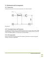
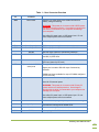
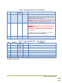
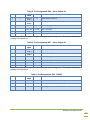
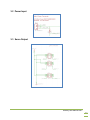
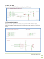
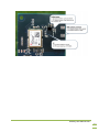
1
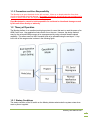
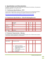
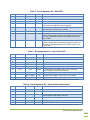
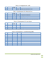
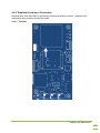
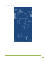
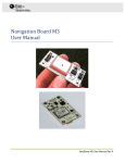
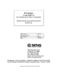
Monkey
User Manual
Monkey User Manual Rev -
Table of Contents
Contents
1.
Introduction ................................................................................................................................ 3
1.1
Limitations .......................................................................................................................... 4
1.1.1
Rate limits ..................................................................................................................... 4
1.1.2
Acceleration limits ......................................................................................................... 4
1.1.3
Magnetic field limits....................................................................................................... 4
1.1.4
GPS .............................................................................................................................. 4
1.1.5
Precautions and User Responsibility ............................................................................. 5
1.2
Theory of Operation ............................................................................................................ 5
1.2.1
Startup Conditions ........................................................................................................ 5
2. Specifications and Characteristics .............................................................................................. 7
2.1
Performance Specifications – CPU ..................................................................................... 7
2.2
Performance Specifications – Global Positioning Receiver ................................................. 7
2.3
Electrical Characteristics – Monkey .................................................................................... 7
2.4
Absolute Maximum Ratings ................................................................................................ 8
2.5
Mechanical and Pin Assignments ....................................................................................... 9
2.5.1
Dimensions ................................................................................................................... 9
2.5.2
Coordinate System and Orientation .............................................................................. 9
2.5.3
Pin Assignments ........................................................................................................... 9
2.5.4
Graphical Location of Connectors ............................................................................... 15
3. Schematic Details..................................................................................................................... 19
3.1
Main ARM Processor ........................................................................................................ 19
3.2
Power Input ...................................................................................................................... 20
3.3
Servo Output .................................................................................................................... 20
3.4
GPS Power and Antenna .................................................................................................. 21
3.5
Reprogramming ................................................................................................................ 22
3.6
USB .................................................................................................................................. 22
3.7
LEDs ................................................................................................................................ 23
3.8
Barometric Pressure Sensor ............................................................................................. 23
3.9
ADC and GPIO ................................................................................................................. 24
3.10 Communication ports ........................................................................................................ 24
3.11 Input Capture port ............................................................................................................. 25
3.12 User I2C and SPI.............................................................................................................. 25
4. Hardware Integration ................................................................................................................ 26
4.1
Power ............................................................................................................................... 26
4.1.1
Input Power ................................................................................................................ 26
4.2
GPS Antenna Options ...................................................................................................... 26
5. Software Interface .................................................................................................................... 28
5.1
Recommended tools ......................................................................................................... 28
5.2
Firmware Upload Procedure ............................................................................................. 28
6. Appendix A – Reprogramming Example ................................................................................... 29
Monkey User Manual Rev -
Release Notes
Title
Subtitle
Type
Document number
Revision Index
Initial Release
Monkey
Monkey User Manual
Manual
UM3000
Date
11/2010
Name
MR
Status / Comments
Initial release
IMPORTANT DISCLAIMERS
This document and the use of any information contained therein, is subject to the acceptance of the Ryan Mechatronics terms and
conditions. They can be downloaded from www.ryanmechatronics.com.
Ryan Mechatronics LLC makes no warranties based on the accuracy or completeness of the contents of this document and reserves the
right to make changes to specifications and product descriptions at any time without notice.
Ryan Mechatronics LLC assumes no liability for damages or otherwise due to use of the information in this document or application of any
device described in this document.
Ryan Mechatronics LLC stresses end user compliance with all applicable laws and regulations when using devices of this nature. Use by
an end user in violation of any applicable laws is automatic basis for termination of warranty, technical support and future sales.
Ryan Mechatronics LLC reserves all rights to this document and the information contained herein. Reproduction, use or disclosure to third
parties without express permission is strictly prohibited.
Copyright © 2010, Ryan Mechatronics LLC
Monkey User Manual Rev -
1. Introduction
The Monkey platform provides a high performance basis for mechatronic system control. Originally
designed for autonomous vehicle control, the platform can also be used for advanced data logging,
industrial control, motion control or other mechatronic applications.
The Monkey 2010 platform is an enhanced version of prior Monkey circuit assemblies. The Monkey
2010 boards include:
o
Powerful base CPU - Cortex M3 (ARM7) LPC 1768 Host Controller
o
Cortex SWD interface (tested with Rowley Crossworks)
o
Hardware based serial boot loader for easy loading of new software
o
High performance U-Blox NEO-5 GPS Module
o Active on board antenna for increased sensitivity and jamming reduction
o
RS-485 driver on board for spare port
o
Barometric pressure sensor
o
Spare analog and digital I/O ports
o
Six (6) Isolated and dedicated PWM servo outputs
o
Four (4) input capture port connector
o
Micro SD Card
o
USB power and interface
o
Three status LED’s (red, green, blue)
o
Interfaces with CHIMU module for attitude estimates and sensor inputs via SPI or UART
Monkey has an excellent GPS module on board (U-Blox series) with both on board and off board
antenna capability. The off board antenna capability is important if the unit is used in conditions
where the on board antenna will be blocked by enclosures or other jamming.
Monkey does not have on board inertial measurement sensors, but is intended to work with the
CHIMU AHRS which includes:
3 axis rate sensors to measure angular rate
3 axis accelerometers to measure linear acceleration
3 axis magnetometer to measure magnetic flux (typically used for compass type heading
derivation)
The combination of all these capabilities with the on board ARM processing power allows a full
attitude heading reference system (AHRS) with GPS position, velocity and time updates all in one
tiny package.
Monkey User Manual Rev -
3
Application areas include, but are not limited to:
UAVs (AUVs, UAS, etc)
Robotics
Education
Rocket science
1.1 Limitations
The unit, like any device designed to utilize GPS and IMU / AHRS data, can be pushed beyond the
limits of its ability to sense any of the measurements it needs to operate correctly. The following list
includes results that are known to occur if operation (when using the CHIMU module) exceeds the
limits listed later in this document.
1.1.1 Rate limits
Saturation of maximum rate in any axis for any amount of time will result in an incorrect attitude
estimate. The longer the saturation duration, the more error will be present in the attitude
determination. A good attitude estimator shall recover once saturation has stopped and the internal
filter has time to reconverge on the correct solution.
Please note: The Monkey does NOT ship with an attitude estimator set of code, but it has the
processing and code memory to host an estimator of the customers design and use raw output from
the CHIMU module.
1.1.2 Acceleration limits
Excessive acceleration can include acceleration above the rated levels in continuous application
(static / low frequency g’s), more elusive vibration (sinusoidal / random) or shock (impulse / random)
events that may not show full saturation of the accelerometers in data output, but have affected the
sensors internally and corrupted the values. Continued acceleration above the limits or excessive
vibration / shock events can corrupt the output acceleration.
1.1.3 Magnetic field limits
Magnetometers are sensitive to hard and soft iron effects, as well as induced magnetic fields from
high current. Saturation of the local magnetic field is easily identified, but lower level influence on
the sensor can result in pervasive errors as well. Calibration of the unit in the final configuration will
help prevent errors introduced by hard iron in the local area. However, induced magnetic fields from
high current devices or high power RF circuitry can result in operational errors. After a proper
calibration, no axis should exceed a +/- 1 gauss value.
1.1.4 GPS
GPS is a phenomenal technology allowing location of your position on the planet Earth within about
a 15 foot (5 meter) accuracy using a module the size of your thumb!
GPS is subject to many possible interference sources, including anything in the GPS frequency band
(including harmonics of lower frequencies from digital systems) and other jamming sources, like
foliage or direct blockage of the antenna.
This manual cannot begin to educate the user on limits of GPS technology, but we recommend both
Wikipedia and the support area on the U-blox (www.ublox.com) website for more information.
Monkey User Manual Rev -
4
1.1.5 Precautions and User Responsibility
The Monkey is an open electrical device with no case. It has no on board protection from short
circuits or accidental electrical damage. No system is fool proof, and all correct use and planning for
events in case of failure are the responsibility of the user.
Ryan Mechatronics cannot be held responsible for accidental or intentional damage caused
by this unit either directly or indirectly.
1.2 Theory of Operation
The Monkey platform is an excellent prototyping system for users that want or need the power of an
ARM Cortex core. User application code can be run on the core. However, the design makes it
easy for the on-board ARM processor to be reprogrammed by using on-board firmware upload
capability. This allows new Intel HEX formatted code to be uploaded using the serial port. A top
level view of the usage modes is shown in the following figure.
1.2.1 Startup Conditions
The startup condition of the S4 switch on the Monkey dictates what mode the system enters when
reset or power is applied.
Monkey User Manual Rev -
5
On Board ARM CPU running user code: For operation in standalone mode, user must have code
loaded and running on the processor. In this case, switch S4 would be in the “RUN” position.
Reprogramming: In order to reprogram the board, switch S4 would be set to “PRG” before power is
applied. When power is applied in this state, the on board boot loader of the ARM is active.
Programming steps in this state can be found in Appendix A – Reprogramming Example .
Monkey User Manual Rev -
6
2. Specifications and Characteristics
Presented in this section are the sensor and system specifications for the Monkey. All parameters
specified are @ VDD = 3.3 V and Ta = 25°C.
2.1 Performance Specifications – CPU
The performance specifications of the LPC1768 core processor are too numerous and detailed to
reproduce here. Please see the following link for specific information on the LPC1768:
http://www.nxp.com/documents/data_sheet/LPC1769_68_67_66_65_64_63.pdf
2.2 Performance Specifications – Global Positioning Receiver
Characteristics
Conditions
Min
Typical
2
29
29
<1
<2.5
<2.0
2
Max
Units
Position, Velocity and Time
Time to First Fix
Horizontal position
accuracy
Max Navigation
Update Rate
Velocity accuracy
External antenna
power supply
Cold Start
Warm Start
Hot Start
Without SBAS
SBAS
Message dependent
Center feed on external antenna
connection
s
m
4
Hz
0.1
m/s
3.3
V
Specifications are subject to change at any time without notice
2.3 Electrical Characteristics – Monkey
The following electrical characteristics relate to the Monkey board with a CHIMU module attached.
Current draw is heavily dependent on code operation.
Characteristics
Conditions
Min
Typical
Max
Units
Power
5V Input Supply
Voltage Range
Vdd
Referenced to GND
4.6
5.0
5.2
V
Current
Average, measured at 5V
110
150
180
mA
48 Mhz core operation
GPS in signal acquisition (track
results in lower current)
CHIMU running
SD card logging 10 Hz data at
1 Hz intervals
PWM active
Specifications are subject to change at any time without notice
Monkey User Manual Rev -
7
2.4 Absolute Maximum Ratings
Parameter
Rating
Acceleration (any axis, 0.5 ms)
Unpowered
Vdd
2000g
Output Short-Circuit Duration
(Any Pin to Common)
Operating Temperature Range
TBD
Storage Temperature Range
-40°C to +125°C
-0.3V to +7V
-30°C to +85°C
Specifications are subject to change at any time without notice
Stresses above those listed under the Absolute Maximum Ratings may cause permanent damage to
the device. This is a stress rating only; functional operation of the device at or near these or any
other conditions above those indicated in the operational section of this specification is not implied.
Exposure to absolute maximum rating conditions for extended periods of time may affect device
reliability.
Drops onto hard surfaces can cause shocks of greater than 2000 g and can exceed the absolute
maximum rating of the device. Exercise care during handling to avoid damage.
Monkey User Manual Rev -
8
2.5 Mechanical and Pin Assignments
2.5.1 Dimensions
Dimensions and outline for the unit are shown below. All units are in inches.
Mounting holes are designed to accommodate standard 4-40 screw sizes.
2.5.2 Coordinate System and Orientation
The Monkey board does not have a coordinate system of its own, but when used with the CHIMU
attitude estimator, it follows a standard (X/Y/Z) coordinate system as shown, where +X is out the
“nose” of the Monkey board, +Y is to the right, and +Z points down.
2.5.3 Pin Assignments
Shown in this section are names for each of the signals on the Monkey connectors, along with
warnings / information as applicable.
Monkey User Manual Rev -
9
Table 1 – User Connector Overview
Connector
ID
SV4
Connector Name /
Function
Main Power
Description
Primary +5V power input to the system and input for
battery voltage monitoring
WARNING: This power pin is common with USB 5V power
and there is limited protection. Overvoltage or shorting this
pin while it is connected to your computer can damage
your computer.
Use either 5V power input, or USB power input. Do not
have multiple power sources connected.
SV5
Servo Output 1-2
PWM output (isolated) for servo channels 1 and 2
SV6
Servo Output 3-4
PWM output (isolated) for servo channels 3 and 4
SV7
Servo Output 5-6
PWM output (isolated) for servo channels 5 and 6
SV8
RS-485
X1
ADC/GPIO
X2
User I2C and SPI
X3
Spare serial and CHIMU
serial ports
RS-485 output (optional, controlled by software)
Four (4) ADC inputs (2 buffered and 2 un-buffered)
and two (2) GPIO lines
User dedicated I2C bus
SPI lines (shared by SD card)
Two (2) 3.3V level serial ports.
Spare port is routed to RS-485 output if selected by
software.
X10
USB
CHIMU serial port available for output if CHIMU configured
for SPI com only
USB communication to ARM (if supported in software)
Used for 5V external power.
WARNING: This power pin is common with Primary 5V
power and there is limited protection. Overvoltage or
shorting this pin while it is connected to your computer can
damage your computer.
Use either 5V power input, or USB power input. Do not
have multiple power sources connected.
X16
Main Com
3.3V level serial port (primary com port to / from Monkey)
X19
Input Capture
J1
SWD
Four (4) input capture ports for servo PWM input capture.
Can also be reconfigured for added GPIO
Serial Wire Debug interface to ARM processor
U40
CHIMU
Allows plug in of CHIMU attitude estimator module
Monkey User Manual Rev -
10
Table 2 - Pin Assignments SV4 – Primary Power
Pin #
Pin Label
1
X
Pin
Name
Vbat
I/O
Description
I
ADC input to ARM intended for battery voltage monitoring.
270 ohm limiting resistor in line, but input voltage must be
scaled off board (i.e. Power Node).
2
5V
5V
N/A
WARNING! This is NOT to be tied directly to a battery. Do
not exceed 3.3V input or damage will occur to unit.
5V external power.
WARNING: This power pin is common with USB 5V power
and there is limited protection. Overvoltage or shorting this
pin while it is connected to your computer can damage
your computer. If using USB power, do not connect this
pin to anything.
Use either 5V power input, or USB power input. Do not
have multiple power sources connected.
3
GND
Ground
N/A
System ground
Table 3 - Pin Assignments SV5 – Servo Output 1/2
Pin #
Pin Label
-
Pin
Name
Servo 1
Output
Servo 2
Output
Servo5V
1
1
2
-
3
I/O
Description
Power
Servo 5V supply
4
-
Servo5V
Power
Servo 5V supply
5
-
GndServo
Ground
Servo Ground
6
6
GndServo
Ground
Servo Ground
O
PWM output for Servo 1
O
PWM output for Servo 2
Servo 5V and Servo Ground are isolated from main system and ground. This can be defeated by
jumping SJ10 and SJ14.
Monkey User Manual Rev -
11
Table 4 - Pin Assignments SV6 – Servo Output 3/4
Pin #
Pin Label
-
Pin
Name
Servo 3
Output
Servo 4
Output
Servo5V
1
1
2
-
3
I/O
Description
Power
Servo 5V supply
4
-
Servo5V
Power
Servo 5V supply
5
-
GndServo
Ground
Servo Ground
6
6
GndServo
Ground
Servo Ground
O
PWM output for Servo 3
O
PWM output for Servo 4
Servo 5V and Servo Ground are isolated from main system and ground. This can be defeated by
jumping SJ10 and SJ14.
Table 5 - Pin Assignments SV7 – Servo Output 5/6
Pin #
Pin Label
-
Pin
Name
Servo 5
Output
Servo 6
Output
Servo5V
1
1
2
-
3
4
I/O
Description
Power
Servo 5V supply
-
Servo5V
Power
Servo 5V supply
5
-
GndServo
Ground
Servo Ground
6
6
GndServo
Ground
Servo Ground
O
PWM output for Servo 5
O
PWM output for Servo 6
Servo 5V and Servo Ground are isolated from main system and ground. This can be defeated by
jumping SJ10 and SJ14.
Table 6 - Pin Assignments SV8 – RS-485
Pin #
Pin Label
I/O
Description
B
Pin
Name
RS_485B
1
2
I/O
B line for RS-485 (differential with A)
A
RS_485A
I/O
A line for RS-485 (differential with B)
3
GND
GND
Ground
System ground
Monkey User Manual Rev -
12
Table 7 - Pin Assignments X1 – ADC/GPIO
Pin #
Pin Label
Pin Name
I/O
Description
1
GP1
GPIO1
I/O
270 ohm current limited I/O to ARM
2
GP0
GPIO0
I/O
270 ohm current limited I/O to ARM
3
AD5
ADC5
ADC
Unbuffered ADC5 to ARM. Do not exceed 3.3V.
4
AD4
ADC4/VBUS
ADC
5
3.3V
3.3V
Power
6
G
GND
Ground
Unbuffered ADC4 to ARM. Do not exceed 3.3V. Alternate
use required for USB com (future upgrade).
3.3V output from on board LDO for use in powering
external signal conditioning or sensors
System ground
7
AD1
ADC1
ADC
8
AD0
ADC0
ADC
Buffered ADC1 to ARM. Buffer is a passive resistor divider
(5k on each leg) that cuts incoming voltage by a factor of 2.
5V input on this line reduced to 2.5V which is within 3.3V
limit of ADC.
Buffered ADC0 to ARM. Buffer is a passive resistor divider
(5k on each leg) that cuts incoming voltage by a factor of 2.
5V input on this line reduced to 2.5V which is within 3.3V
limit of ADC.
For ARM pins, typical use is shown but can be reconfigured. Please see the LPC1768 User Manual from NXP for other pin options.
Table 8 - Pin Assignments X2 – User I2C and SPI
Pin #
Pin Label
Pin Name
I/O
Description
1
-
SD_!CS_ALT
I/O
Chip select alternate
2
-
SD_MOSI0
I/0
MOSI0 to ARM
3
-
SD_MIOS0
I/O
MIOS0 to ARM
4
-
SD_!CS0
I/O
!CS to ARM
5
-
SD_CLK0
I/O
CLK0 to ARM
6
3.3V
3.3V
Power
7
G
GND
Ground
3.3V output from on board LDO for use in powering
external signal conditioning or sensors
System ground
8
-
SCL1_USER
I2C
I2C SCL line to ARM. 1k pull-up to 3.3V on board
9
-
SDA1_USER
I2C
I2C SDA line to ARM. 1k pull-up to 3.3V on board
For ARM pins, typical use is shown but can be reconfigured. Please see the LPC1768 User Manual from NXP for other pin options.
Table 9 - Pin Assignments X3 – Spare Serial Communication
Pin #
Pin Label
Pin Name
I/O
Description
1
-
SP_TX
I/O
UART TX1 (3.3V level)
2
-
SP_RX
I/O
UART RX1 (3.3V level)
3
-
3.3V
Power
4
-
GND
Ground
5
-
CHIMU_RX
I/O
UART RX3 (3.3V level)
6
-
CHIMU_TX
I/O
UART TX3 (3.3V level)
3.3V output from on board LDO for use in powering
external signal conditioning or sensors
System ground
For ARM pins, typical use is shown but can be reconfigured. Please see the LPC1768 User Manual from NXP for other pin options.
Monkey User Manual Rev -
13
Table 10 - Pin Assignments X10 – USB
Pin #
Pin Label
1-4
-
Pin
Name
-
I/O
Mixed
Description
Standard 4 pin USB connector, mini-B
Table 11 - Pin Assignments X16 – Main Serial Com
Pin #
Pin Label
Pin
Name
3.3V
1
-
2
3
4
I/O
Description
Power
3.3V output from on board LDO
-
GND
Ground
System ground
-
COM_RX
I/O
UART RX0 (3.3V level)
-
COM_TX
I/O
UART TX0 (3.3V level)
For ARM pins, typical use is shown but can be reconfigured. Please see the LPC1768 User Manual from NXP for other pin options.
Table 12 - Pin Assignments X19 – Input Capture
Pin #
Pin Label
I/O
-
Pin
Name
CAP 1.1
1
Description
I/O
Capture pin 1.1
2
-
CAP 1.0
I/O
Capture pin 1.0
3
-
CAP 0.1
I/O
Capture pin 0.1
4
-
CAP 0.0
I/O
Capture pin 0.0
For ARM pins, typical use is shown but can be reconfigured. Please see the LPC1768 User Manual from NXP for other pin options.
Table 13 - Pin Assignments J1 – Serial Wire Debug (SWD)
Pin #
Pin Label
Pin Name
I/O
Description
1
-
3.3V
Power
2
-
TMS/SWDIO
I/O
SWD standard
3
-
GND
Ground
System ground
4
-
TCK/SWCLK
I/O
SWD standard
5
-
GND
Ground
System ground
6
-
TDO/SWO
I/O
SWD standard
7
-
RTCK
I/O
SWD standard
8
-
TDI
I/O
SWD standard
9
-
GND
Ground
System ground
10
-
!RESET
I/O
SWD standard
3.3V power
Monkey User Manual Rev -
14
2.5.4 Graphical Location of Connectors
Reprinted here is the silkscreen for the Monkey board top and bottom artwork. Locations of all
components and connectors can be found here.
2.5.4.1 Top Side
Monkey User Manual Rev -
15
Monkey User Manual Rev -
16
2.5.4.2 Bottom Side
Monkey User Manual Rev -
17
Monkey User Manual Rev -
18
3. Schematic Details
Presented in this section are schematic details required for users to correctly program the board for
alternate applications.
3.1 Main ARM Processor
Pins for the ARM connection are shown below for reference.
Monkey User Manual Rev -
19
3.2 Power Input
3.3 Servo Output
Monkey User Manual Rev -
20
3.4 GPS Power and Antenna
For GPS power always on, jump SJ6 to R9 (this is default for shipping). If power to GPS needs to
be shut off to conserve power, jump SJ6 to GPS_PWR_SHTDN and power control is dictated by
ARM processor code.
For onboard active antenna, L_VCC_RF is NO POP. For off board active antenna, L_VCC_RF
inductor of 27nH should be installed (0603 pads). SJ9 must be selected correctly for either onboard
or off board. DO NOT connect / jump both to this solder bridge pad.
Monkey User Manual Rev -
21
3.5 Reprogramming
SWD connector J1 is shown here.
3.6 USB
USB communication is not part of the Monkey base code. However, Monkey can be powered from a
USB connection for easy bench testing and future code will support USB communication.
Monkey User Manual Rev -
22
3.7 LEDs
LEDs (green, red and blue) are controlled by the ARM.
3.8 Barometric Pressure Sensor
The barometric pressure sensor is light sensitive, and is located under the CHIMU module holder.
Monkey User Manual Rev -
23
3.9 ADC and GPIO
Connector X1 is a mix of ADC (buffered and unbuffered) and GPIO signals.
3.10 Communication ports
Main com is on X16. Spare com is on X3 and can be routed thru the RS-485 driver to SV8.
ARM-CHIMU serial port can be used as well if the CHIMU serial pins are disabled or if CHIMU is not
present.
Monkey User Manual Rev -
24
3.11 Input Capture port
Input capture (or GPIO if desired) connection is on X19.
3.12 User I2C and SPI
User I2C lines and SPI pins are located on X2. SPI pins are common with the SD card, and can be
used for debugging SD operation or for an alternate SPI device if SD card is not used.
Monkey User Manual Rev -
25
4. Hardware Integration
Presented in this section are selected hardware interface comments to help ease integration of the
unit in the end user system.
Please note - the Monkey is an open electrical device with no case. It has no on board protection
from short circuits or accidental electrical damage. No system is fool proof, and all correct use and
planning for events in case of failure are the responsibility of the user.
Ryan Mechatronics cannot be held responsible for accidental or intentional damage caused
by this unit either directly or indirectly.
4.1 Power
4.1.1 Input Power
Input power to the board is 5V but the Monkey core electronics all operate internally off of 3.3V
generated via an on board low dropout linear regulator. There are three methods for powering the
board. 5V input, USB (5V) input or 5V input from a servo connection (after modification to the solder
jumpers that remove isolation of the servo signals, which is not recommended).
The 5V input on SV4 is common to the USB power bus. If you provide 5V power to the board, the
onboard regulator will generate 3.3V output for the electronics.
Do NOT supply more than one power supply to the unit (i.e. USB power and 5V). This will
ultimately lead to damage of the Monkey or your PC.
Critical Warning: When using USB power, the bare circuit board is powered by your USB
port. Shorting the unit out or overvoltaging it can directly damage your PC. Take extra
precaution when using it directly interfaced to your PC.
4.2 GPS Antenna Options
The Monkey has an on board active patch antenna for GPS reception, but with a solder jumper,
inductor, edge SMA connector and user supplied antenna, an external antenna to be used instead.
The graphic below shows how to enable / disable the onboard passive antenna or the external
antenna. Only one or the other may be used at one time.
Monkey User Manual Rev -
26
Monkey User Manual Rev -
27
5. Software Interface
A set of core Monkey base software will soon be released as open source and can be found at
www.ryanmechatronics.com. Monkey is intended for developers, so all functionality, while tested,
may not be included in this source code. Any missing desired code is the responsibility of the user
and not the responsibility of Ryan Mechatronics.
5.1 Recommended tools
We highly recommend using Rowley Crossworks (http://www.rowley.co.uk) Crossworks for ARM as
the tool for reprogramming the Monkey. Rowley tools are very simple to use and based on the GCC
compiler chain.
In addition to the Crossworks package, the CrossConnect LITE and SWD adapter should be
purchased if debugging on board using the SWD connector is planned.
5.2 Firmware Upload Procedure
Firmware can be uploaded using the SWD connector and suitable Cortex debugging tools, or it can
be uploaded via the serial port as an Intel HEX formatted file. An example of uploading firmware via
this method can be found in Appendix A – Reprogramming Example.
Monkey User Manual Rev -
28
6. Appendix A – Reprogramming Example
Steps to load a new Hex file (firmware image) into the Monkey 2010 board
1)
2)
3)
4)
5)
6)
7)
Download and install the latest version of FlashMagic from this site:
(http://www.flashmagictool.com/)
Power down Monkey
Remove CHIMU module (if present) from Monkey board (to be on the safe side)
Plug USB node or other USB to serial converter into Monkey
Move the S4 switch on Monkey away from RUN (this is a little slide switch near the USB
connector)
Power up Monkey
Run FlashMagic and reprogram
a. Open settings file (.fms), or if .fms file is not available, select settings shown below
b. Change COM port to your com port
Monkey User Manual Rev -
29
8)
9)
10)
11)
12)
c. Change path to .hex file to where you stored the hex file to download
d. Press the “start” button, it will flash and verify
e. If it fails, try pressing the reset button on the Monkey board and try again
f. If it still fails, try powering the unit via a USB cable so grounds are common
g. If it still fails, drop the baud rate to 57600
h. If it still fails, cycle power on the Monkey and try again
Close FlashMagic
Power board down
Flip switch S4 to RUN
Put CHIMU back on (be CAREFUL ABOUT PIN ALIGNMENT!)
Power up and verify new code is running
Monkey User Manual Rev -
30