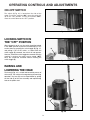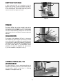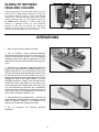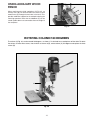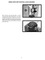
1
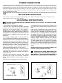
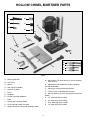
(Model MM300)
PART NO. 906119 - 06-15-02
Copyright © 2002 Delta Machinery
To learn more about DELTA MACHINERY
visit our website at: www.deltamachinery.com.
For Parts, Service, Warranty or other Assistance,
please call
ESPAÑOL: PÁGINA 19
1-800-223-7278 (In Canada call 1-800-463-3582).
INSTRUCTION MANUAL
Hollow Chisel
Mortiser
GENERAL SAFETY RULES
Woodworking can be dangerous if safe and proper operating procedures are not followed. As with all machinery, there
are certain hazards involved with the operation of the product. Using the machine with respect and caution will
considerably lessen the possibility of personal injury. However, if normal safety precautions are overlooked or ignored,
personal injury to the operator may result. Safety equipment such as guards, push sticks, hold-downs, featherboards,
goggles, dust masks and hearing protection can reduce your potential for injury. But even the best guard won’t make
up for poor judgment, carelessness or inattention. Always use common sense and exercise caution in the workshop.
If a procedure feels dangerous, don’t try it. Figure out an alternative procedure that feels safer. REMEMBER: Your
personal safety is your responsibility.
This machine was designed for certain applications only. Delta Machinery strongly recommends that this machine not
be modified and/or used for any application other than that for which it was designed. If you have any questions relative
to a particular application, DO NOT use the machine until you have first contacted Delta to determine if it can or should
be performed on the product.
Technical Service Manager
Delta Machinery
4825 Highway 45 North
Jackson, TN 38305
(IN CANADA: 505 SOUTHGATE DRIVE, GUELPH, ONTARIO N1H 6M7)
WARNING: FAILURE TO FOLLOW THESE RULES MAY RESULT IN SERIOUS PERSONAL INJURY
1. FOR YOUR OWN SAFETY, READ INSTRUCTION
MANUAL BEFORE OPERATING THE TOOL. Learn the
tool’s application and limitations as well as the specific
hazards peculiar to it.
2. KEEP GUARDS IN PLACE and in working order.
3. ALWAYS WEAR EYE PROTECTION. Wear safety
glasses. Everyday eyeglasses only have impact resistant
lenses; they are not safety glasses. Also use face or dust
mask if cutting operation is dusty. These safety glasses
must conform to ANSI Z87.1 requirements. NOTE:
Approved glasses have Z87 printed or stamped on them.
4. REMOVE ADJUSTING KEYS AND WRENCHES. Form
habit of checking to see that keys and adjusting wrenches
are removed from tool before turning it “on”.
5. KEEP WORK AREA CLEAN. Cluttered areas and
benches invite accidents.
6. DON’T USE IN DANGEROUS ENVIRONMENT. Don’t
use power tools in damp or wet locations, or expose them
to rain. Keep work area well-lighted.
7. KEEP CHILDREN AND VISITORS AWAY. All children
and visitors should be kept a safe distance from work area.
8. MAKE WORKSHOP CHILDPROOF – with padlocks,
master switches, or by removing starter keys.
9. DON’T FORCE TOOL. It will do the job better and be
safer at the rate for which it was designed.
10. USE RIGHT TOOL. Don’t force tool or attachment to
do a job for which it was not designed.
11. WEAR PROPER APPAREL. No loose clothing, gloves,
neckties, rings, bracelets, or other jewelry to get caught in
moving parts. Nonslip footwear is recommended. Wear
protective hair covering to contain long hair.
12. SECURE WORK. Use clamps or a vise to hold work
when practical. It’s safer than using your hand and frees
both hands to operate tool.
13. DON’T OVERREACH. Keep proper footing and
balance at all times.
14. MAINTAIN TOOLS IN TOP CONDITION. Keep tools
sharp and clean for best and safest performance. Follow
instructions for lubricating and changing accessories.
15. DISCONNECT TOOLS before servicing and when
changing accessories such as blades, bits, cutters, etc.
16. USE RECOMMENDED ACCESSORIES. The use of
accessories and attachments not recommended by Delta
may cause hazards or risk of injury to persons.
17. REDUCE THE RISK OF UNINTENTIONAL STARTING.
Make sure switch is in “OFF” position before plugging in
power cord. In the event of a power failure, move switch
to the “OFF” position.
18. NEVER STAND ON TOOL. Serious injury could occur if
the tool is tipped or if the cutting tool is accidentally
contacted.
19. CHECK DAMAGED PARTS. Before further use of the
tool, a guard or other part that is damaged should be
carefully checked to ensure that it will operate properly and
perform its intended function – check for alignment of
moving parts, binding of moving parts, breakage of parts,
mounting, and any other conditions that may affect its
operation. A guard or other part that is damaged should be
properly repaired or replaced.
20. DIRECTION OF FEED. Feed work into a blade or
cutter against the direction of rotation of the blade or cutter
only.
21. NEVER LEAVE TOOL RUNNING UNATTENDED.
TURN POWER OFF. Don’t leave tool until it comes to a
complete stop.
22. STAY ALERT, WATCH WHAT YOU ARE DOING, AND
USE COMMON SENSE WHEN OPERATING A POWER
TOOL. DO NOT USE TOOL WHILE TIRED OR UNDER
THE INFLUENCE OF DRUGS, ALCOHOL, OR
MEDICATION. A moment of inattention while operating
power tools may result in serious personal injury.
23. MAKE SURE TOOL IS DISCONNECTED FROM
P O W E R S U P P LY w h i l e m o t o r i s b e i n g m o u n t e d ,
connected or reconnected.
24. THE DUST GENERATED by certain woods and wood
products can be injurious to your health. Always operate
machinery in well ventilated areas and provide for proper
dust removal. Use wood dust collection systems whenever
possible.
25.
WARNING: SOME DUST CREATED BY
POWER SANDING, SAWING, GRINDING, DRILLING,
AND OTHER CONSTRUCTION ACTIVITIES contains
chemicals known to cause cancer, birth defects or other
reproductive harm. Some examples of these chemicals
are:
· lead from lead-based paints,
· crystalline silica from bricks and cement and other
masonry products, and
· arsenic and chromium from chemically-treated lumber.
Your risk from these exposures varies, depending on how
often you do this type of work. To reduce your exposure
to these chemicals: work in a well ventilated area, and
work with approved safety equipment, such as those
dust masks that are specially designed to filter out
microscopic particles.
SAVE THESE INSTRUCTIONS.
Refer to them often and use them to instruct others.
2
ADDITIONAL SAFETY RULES FOR
HOLLOW CHISEL MORTISERS
WARNING: FAILURE TO FOLLOW THESE RULES MAY RESULT IN SERIOUS PERSONAL INJURY.
1. DO NOT OPERATE THIS MACHINE until it is
assembled and installed according to the instructions.
15. ALWAYS turn off the power before removing scrap
pieces from the table.
2. OBTAIN ADVICE FROM YOUR SUPERVISOR,
instructor, or another qualified person if you are not
familiar with the operation of this machine.
16. SHUT-OFF the power, remove the drill bit and chisel,
and clean the table before leaving the machine.
17. FOR YOUR OWN SAFETY – Don’t wear gloves when
operating the machine.
3. FOLLOW ALL WIRING CODES and recommended
electrical connections.
5. NEVER turn the mortiser “ON” before clearing the
table of all objects (tools, scrap pieces, etc.).
18. SHOULD any part of your tool be missing, damaged, or
fail in any way, or any electrical component fail to perform
properly, shut off switch and remove plug from power
supply outlet. Replace missing, damaged, or failed parts
before resuming operation.
6. ALWAYS keep hands, fingers and hair away from
the rotating bit.
19. THE USE of attachments and accessories not
recommended by Delta may result in the risk of injuries.
7. DO NOT attempt to mortise material that does not
have a flat surface, unless a suitable support is used.
20. TURN THE MACHINE “OFF” AND DISCONNECT
THE MACHINE from the power source before installing
or removing accessories, before adjusting or changing
set-ups, or when making repairs.
4. MAKE CERTAIN the machine is fastened to a supporting
surface to prevent it from tipping over during operation.
8. ALWAYS position holddown directly over workpiece
to prevent workpiece from lifting during operation.
21. TURN THE MACHINE “OFF”, disconnect the
machine from the power source, and clean the
table/work area before leaving the machine. LOCK THE
SWITCH IN THE “OFF” POSITION to prevent
unauthorized use.
9. ALWAYS support workpiece securely against fence
to prevent rotation.
10. BE SURE drill bit is sharp, not damaged, and properly
secured in the chuck before operation.
11. MAKE SURE chuck key is removed before starting
machine.
22. ADDITIONAL INFORMATION regarding the safe
and proper operation of this tool is available from the
Power Tool Institute, 1300 Summer Avenue, Cleveland,
OH 44115-2851. Information is also available from the
National Safety Council, 1121 Spring Lake Drive, Itasca,
IL 60143-3201. Please refer to the American National
Standards Institute ANSI 01.1 Safety Requirements for
Woodworking Machines and the U.S. Department of
Labor OSHA 1910.213 Regulations.
12. NEVER turn on the power with the drill bit or chisel
contacting the workpiece.
13. NEVER perform layout, assembly, or set-up work on
the table while the mortiser is operating.
14. ADJUST the depth stop to avoid drilling into the
table.
SAVE THESE INSTRUCTIONS.
Refer to them often
and use them to instruct others.
3
POWER CONNECTIONS
A separate electrical circuit should be used for your machines. This circuit should not be less than #12 wire and should
be protected with a 20 Amp time lag fuse. If an extension cord is used, use only 3-wire extension cords which have 3prong grounding type plugs and matching receptacle which will accept the machine’s plug. Before connecting the
motor to the power line, make sure the switch is in the “OFF” position and be sure that the electric current is of the
same characteristics as indicated on the machine. All line connections should make good contact. Running on low
voltage will damage the motor.
WARNING: DO NOT EXPOSE THE MACHINE TO RAIN OR OPERATE THE MACHINE IN DAMP LOCATIONS.
MOTOR SPECIFICATIONS
Your machine is wired for 120 volt, 60 HZ alternating current. Before connecting the machine to the power source,
make sure the switch is in the “OFF” position.
GROUNDING INSTRUCTIONS
WARNING: THIS MACHINE MUST BE GROUNDED WHILE IN USE TO PROTECT THE OPERATOR FROM
ELECTRIC SHOCK.
1. All grounded, cord-connected machines:
2. Grounded, cord-connected machines intended for use
on a supply circuit having a nominal rating less than 150
In the event of a malfunction or breakdown, grounding
volts:
provides a path of least resistance for electric current to
reduce the risk of electric shock. This machine is
If the machine is intended for use on a circuit that has an
equipped with an electric cord having an equipmentoutlet that looks like the one illustrated in Fig. A, the
grounding conductor and a grounding plug. The plug must
machine will have a grounding plug that looks like the plug
be plugged into a matching outlet that is properly installed
illustrated in Fig. A. A temporary adapter, which looks like
and grounded in accordance with all local codes and
the adapter illustrated in Fig. B, may be used to connect
ordinances.
this plug to a matching 2-conductor receptacle as shown
in Fig. B if a properly grounded outlet is not available. The
Do not modify the plug provided - if it will not fit the outlet,
temporary adapter should be used only until a properly
have the proper outlet installed by a qualified electrician.
grounded outlet can be installed by a qualified electrician.
Improper connection of the equipment-grounding
The green-colored rigid ear, lug, and the like, extending
conductor can result in risk of electric shock. The
from the adapter must be connected to a permanent
conductor with insulation having an outer surface that is
ground such as a properly grounded outlet box. Whenever
green with or without yellow stripes is the equipmentthe adapter is used, it must be held in place with a metal
grounding conductor. If repair or replacement of the
screw.
electric cord or plug is necessary, do not connect the
equipment-grounding conductor to a live terminal.
NOTE: In Canada, the use of a temporary adapter is not
permitted by the Canadian Electric Code.
Check with a qualified electrician or service personnel if
t h e g ro u n d i n g i n s t r u c t i o n s a re n o t c o m p l e t e l y
understood, or if in doubt as to whether the machine is
WARNING: IN ALL CASES, MAKE CERTAIN THE
properly grounded.
RECEPTACLE IN QUESTION IS PROPERLY
G R O U N D E D . I F Y O U A R E N O T S U R E H AV E A
Use only 3-wire extension cords that have 3-prong
QUALIFIED ELECTRICIAN CHECK THE RECEPTACLE.
grounding type plugs and matching 3-conductor
receptacles that accept the machine’s plug, as shown in
Fig. A.
Repair or replace damaged or worn cord immediately.
GROUNDED OUTLET BOX
GROUNDED OUTLET BOX
GROUNDING
MEANS
CURRENT
CARRYING
PRONGS
ADAPTER
GROUNDING BLADE
IS LONGEST OF THE 3 BLADES
Fig. A
4
Fig. B
EXTENSION CORDS
Use proper extension cords. Make sure your extension cord is in good condition and is a 3-wire extension cord which
has a 3-prong grounding type plug and matching receptacle which will accept the machine’s plug. When using an
extension cord, be sure to use one heavy enough to carry the current of the machine. An undersized cord will cause
a drop in line voltage, resulting in loss of power and overheating. Fig. D, shows the correct gauge to use depending
on the cord length. If in doubt, use the next heavier gauge. The smaller the gauge number, the heavier the cord.
MINIMUM GAUGE EXTENSION CORD
RECOMMENDED SIZES FOR USE WITH STATIONARY ELECTRIC MACHINES
Ampere
Rating
Volts
Total Length
of Cord in Feet
Gauge of
Extension Cord
0-6
0-6
0-6
0-6
120
120
120
120
up to 25
25-50
50-100
100-150
18 AWG
16 AWG
16 AWG
14 AWG
6-10
6-10
6-10
6-10
120
120
120
120
up to 25
25-50
50-100
100-150
18 AWG
16 AWG
14 AWG
12 AWG
10-12
10-12
10-12
10-12
120
120
120
120
up to 25
25-50
50-100
100-150
16 AWG
16 AWG
14 AWG
12 AWG
12-16
12-16
12-16
120
120
120
up to 25
25-50
14 AWG
12 AWG
GREATER THAN 50 FEET NOT RECOMMENDED
Fig. D
OPERATING INSTRUCTIONS
FOREWORD
Delta ShopMaster Model MM300 is easier to operate than a conventional drill press equipped with a mortising
attachment. The model MM300 is made of cast-iron and steel for rigidity and stability. The motriser comes with a
standard 3-jaw type key chuck for positive gripping of mortising bits.
UNPACKING AND CLEANING
Carefully unpack the machine and all loose items from the shipping container(s). Remove the protective coating from
all unpainted surfaces. This coating may be removed with a soft cloth moistened with kerosene (do not use acetone,
gasoline or lacquer thinner for this purpose). After cleaning, cover the unpainted surfaces with a good quality household
floor paste wax.
NOTICE: THE MANUAL COVER PHOTO ILLUSTRATES THE CURRENT
PRODUCTION MODEL. ALL OTHER ILLUSTRATIONS ARE REPRESENTATIVE
ONLY AND MAY NOT DEPICT THE ACTUAL COLOR, LABELING OR
ACCESSORIES AND MAY BE INTENDED TO ILLUSTRATE TECHNIQUE ONLY.
5
HOLLOW CHISEL MORTISER PARTS
O
L
M
P
A
N
Q
D
C
B
E
K
F
G
I
R
S
J
H
T
U
Fig. 2
A - Mortising Machine
M - M6x1x35mm Flat Head Screws (2) (for assembling
table to base)
B - Chuck Key
N - M6x1x25mm Pan Head Screws (2) (for assembling
tool and chisel holder)
C - Wrench
D - Tool and Chisel Holder
O - Spring (for raising and lowering handle)
E - Hydraulic Cylinder
P - T-Nuts (2) (for assembling table to base)
F - Fence
G - Holddown
Q - M6 Flat Washers (2) (for assembling tool and chisel
holder)
H - Bar (for mounting holddown)
R - 1/2" Mortising Chisel and Bit
I - Table
S - 3/8" Mortising Chisel and Bit
J - Raising and Lowering Handle
T - 5/16" Mortising Chisel and Bit
K - Fence Locking Handle Assembly
U - 1/4" Mortising Chisel and Bit
L - Special Screw (for raising and lowering handle)
6
ASSEMBLY
WARNING: FOR YOUR OWN SAFETY, DO NOT CONNECT THE MACHINE TO THE POWER SOURCE UNTIL THE
MACHINE IS COMPLETELY ASSEMBLED AND YOU READ AND UNDERSTAND THE ENTIRE INSTRUCTION
MANUAL.
B
RAISING AND LOWERING
HANDLE
A
1. Assemble hub of handle assembly (A) Fig. 3, to end
of pinion shaft (B) and fasten handle to pinion shaft
using special screw (C) and spring (D).
D
C
Fig. 3
B
2. Raise mortising machine head (E) Fig. 4, to the up
position by turning handle (A) clockwise. NOTE: Handle
(A) is spring-loaded and can be repositioned by pulling
out handle and repositioning it on pinion shaft (B).
A
E
Fig. 4
HYDRAULIC CYLINDER
A
1. Make sure head (A) Fig. 5, is held in the up position
and assemble the hydraulic cylinder (B) to the two
fittings (C), one located on the column and the other on
the back of the head.
B
C
Fig. 5
2. Fig. 6, illustrates the hydraulic cylinder (B) assembled
to the machine. The hydraulic cylinder (B) keeps the
head in the up position.
B
Fig. 6
7
TABLE
1. Assemble the table (A) Fig. 7, to the base using the
two M6x1x35mm flat head screws (B) and T-nuts (C).
Insert the two screws (B) into the two holes (D) in table
(A). Place the two T-nuts (C) into the slots (E) provided in
the bottom of the base and tighten the two screws (B)
into the two T-nuts (C) securely.
E
A
D
C
B
E
2. The table (A) Fig. 7, can be moved in or out by
loosening the two screws (B), and re-positioning the
table, and then tightening screws (B).
Fig. 7
FENCE AND HOLDDOWN
C
1. Locate handle assembly and remove screw (A) Fig. 8,
and spring (B) from handle (C). Sperate handle (C) from
stud (D).
D
B
A
Fig. 8
2. Thread stud (D) Fig. 9, into hole on side of column,
as shown. Do not thread stud (D) all the way into hole at
this time.
D
3. Reassemble handle (C) Fig. 9, on stud (D) and replace screw (A) and spring (B).
C
B
A
Fig. 9
4. Fig. 10 illustrates the handle assembly (C) attached to
the column.
C
Fig. 10
8
5. Insert bar of fence assembly (E) Fig. 11, through
hole in column as shown. Tighten handle (C) against flat
on fence bar to hold fence in position. NOTE: Handle (C)
is spring-loaded and can be repositioned on the stud
located underneath the handle by pulling out the handle
and repositioning it on the stud.
E
C
Fig. 11
6. Insert bar (F) Fig. 12, into hole on top of fence as
shown, and tighten set screw (G) against flat on bar (F).
F
G
Fig. 12
7. Assemble the holddown (H) Fig. 13, onto bar (F) as
shown, and tighten set screw (J) against flat on bar.
H
J
F
TOOL AND CHISEL HOLDER
1. Assemble tool and chisel holder (A) Fig. 14, to side
of column using the two M6x1x25mm screws (B) and
M6 flat washers as shown.
Fig. 13
2. Fig. 15, illustrates the chuck key (C), wrench (D) and
chisels and bits (E) in holes of tool and chisel holder (A)
when not in use.
E
D
B
C
A
A
Fig. 14
Fig. 15
9
FASTENING MACHINE TO SUPPORTING SURFACE
If during operation there is any tendency for the mortiser
to tip over, slide or walk on the supporting surface, the
base must be secured to the supporting surface with
fasteners (not supplied), through the two holes (A) Fig.
16, located in the mortiser base.
A
A
Fig. 16
ASSEMBLING CHISEL AND BIT
1. DISCONNECT MACHINE FROM POWER SOURCE.
A
2. Insert bit (A) Fig. 20, into chisel (B). NOTE: The
opening (C) on the side of the chisel should always be to
the right or left, never to the front or rear. The opening
allows chips to escape during operation.
B
C
Fig. 20
D
B
3. Loosen screw (D) Fig. 21, and push chisel (B) up
through hole in head as far as possible. Then lower chisel
(B) 1/16" to 3/16" and tighten set screw (D). IMPORTANT:
When inserting chisel (B) Fig. 22 into head, there must
be a space of 1/16" to 3/16" clearance (F) between the
bushing (E) and shoulder of chisel (B) as shown. This
assures having proper clearance between the cutting
lips of the bit and points of the chisel after the bit is
inserted into the chuck.
Fig. 21
D
E
F
B
Fig. 22
10
4. Push bit (A) Fig. 23, up through chisel and into
chuck (G) as far as it will go, and lock bit in chuck using
chuck key supplied.
G
A
Fig. 23
5. Loosen set screw (D) Fig. 24, and push chisel (B) up
against bottom of bushing (E), as shown, and tighten set
screw (D). This should provide the proper distance between the cutting lips of the bit and the points of the
chisel.
D
E
B
Fig. 24
6. The flat portion of the bit should be adjusted to a
minimum of 1/16" below the bottom of the chisel, as
shown in Fig. 25. For certain types of wood it may be
necessary to increase this distance up to a maximum of
3/16" clearance. This method assures having proper
clearance between the cutting edges of the bit and the
points of the chisel.
PUSH
CHISEL UP
AGAINST
BUSHING
ADJUST BIT IN
CHUCK TO GIVE
CLEARANCE
/16" to 3/16"
CLEARANCE TO SUIT
TYPE OF WOOD
1
Fig. 25
11
OPERATING CONTROLS AND ADJUSTMENTS
ON-OFF SWITCH
The switch (A) Fig. 26, is located on the side of the
motor. To turn the machine “ON”, move the switch (A),
up to the “ON” position. To turn the machine “OFF”,
move the switch down to the “OFF” position.
A
Fig. 26
LOCKING SWITCH IN
THE “OFF” POSITION
When the tool is not in use, the switch should be locked
in the “OFF” position to prevent unauthorized use. This
can be done by grasping the switch toggle (B) Fig. 27,
and pulling it out of the switch, as shown. With the
switch toggle (B) removed, the switch will not operate.
However, should the switch toggle be removed while the
machine is running, the switch can be turned “OFF”
once, but cannot be restarted without inserting the
switch toggle (B).
B
Fig. 27
RAISING AND
LOWERING THE HEAD
The head (A) Fig. 28, is raised and lowered by means of
the lever (B). For maximum leverage during the mortising
operation, the lever (B) can be repositioned by pulling
out the hub (C) of the lever assembly and repositioning
hub on the pinion shaft.
B
A
C
Fig. 28
12
DEPTH STOP ROD
C
A depth stop rod (A) Fig. 29, is provided to limit the
depth of the chisel (B). To adjust the depth stop rod (A),
loosen screw (C) and lower head until the chisel (B) is
at the desired depth. Lower depth stop rod (A) until it
contacts base (D) and tighten screw (C).
A
B
D
Fig. 29
FENCE
The fence (A) Fig. 30, can be moved in or out by
loosening lever (B), sliding fence to the desired position
and tightening lever (B). NOTE: Lever (B) is spring-loaded
and can be repositioned by pulling out on the lever and
repositioning it on the serrated nut located underneath
the lever.
D
C
F
E
HOLDDOWN
B
The purpose of the holddown (C) Fig. 30, is to prevent
the workpiece (E) from lifting as the chisel (D) is raised
up, out of the hole. The holddown (C) should be adjusted
so it just touches the top of the workpiece (E) and allows
the workpiece to slide left or right. The holddown (C) can
be turned upside down to accommodate thicker
workpieces. To adjust the holddown (C), loosen screw
(F), position holddown, and tighten screw (F).
A
Fig. 30
CHISEL PARALLEL TO
WORKPIECE
B
The chisel (A) Fig. 31, can be adjusted parallel to the
workpiece by loosening screw (B) and rotating chisel
until the back surface of the chisel is touching
workpiece. Then tighten screw (B).
A
Fig. 31
13
SLIDING FIT BETWEEN
HEAD AND COLUMN
B
A dovetail gib (A) Fig. 32, is provided on the rear of the
head to insure a good sliding fit between the head and
the column when the head is raised and lowered.
Adjustment is made by loosening the two screws (B) and
turning adjusting screws (C). Then tighten two screws
(B). NOTE: Correct adjustment is when a good snug
sliding fit is obtained without any side movement
between the gib and the column. This adjustment
should not be too tight that it restricts the sliding
movement or too loose that it affects accuracy.
A
C
B
Fig. 32
OPERATIONS
1. Make sure that chisels and bits are sharp.
B
A
2. Fig. 33, illustrates a typical mortising operation.
Note that the opening (A) in the chisel is to the right. This
means that after the first incision is cut, the workpiece
should be moved to the right for subsequent cuts. This
allows chips to escape freely through the opening in the
chisel.
3. Make sure the workpiece is held firmly against the
fence when cutting and that the holddown (B) Fig. 33, is
properly adjusted. The rate of penetration of the chisel
must be fast enough to prevent burning at the tip of the
bit, but not too fast as to stall the motor. You may encounter smoke from the bit or material once the chisel has
engaged the material. The smoke created is a natural
operating occurrence in hollow chisel mortising and is
caused by material chip friction and the resins in the
stock being burned off. Bluing of the chisel after initial
use is not indicative of a dull chisel, but a combination
of friction and resin buildup on the cutting faces of the
chisel. A dull chisel can be detected by the amount of
excess force required to complete a cut.
Fig. 33
4. When performing a through mortise, a thin piece of
wood should be placed between the workpiece and the
table. This prevents “chip-out” at the bottom of the
mortise and also prevents damage to the table.
5. Fig. 34,
completed.
illustrates
the
mortising
operation
Fig. 34
14
USING AUXILIARY WOOD
FENCE
E
A
When mortising extra high workpieces (A) Fig. 35, an
auxiliary fence (B) can be fastened to the fence (C) with
wood screws (D) through the two holes in the fence. This
provides additional support for the workpiece during the
mortising operation. Note that the holddown (E) can be
turned upside down to accommodate the extra height of
the workpiece.
B
D
C
Fig. 35
ROTATING COLUMN 180 DEGREES
The column (A) Fig. 36, can be rotated 180 degrees, as shown, if it is desired to use workpieces off the table. To rotate
the column, remove three screws, two of which are shown at (B), rotate column (A) 180 degrees and replace the three
screws (B).
A
B
Fig. 36
15
USING BITS WITH EXTRA LONG SHANKS
A
C
When using bits with extra long shanks, it will be
necessary to remove the extension (A) Fig. 37. This can be
accomplished by inserting screwdriver into center hole
of motor end cap (B) Fig. 38, and into slot in end of
armature shaft. Then using chuck key, unscrew and
remove chuck (C) Fig. 37, and extension (A). Remove
extension (A) from chuck (C) and replace chuck (C) on
end of motor shaft.
Fig. 37
B
Fig. 38
16
NOTES
17
ACCESSORIES
A complete line of accessories is available from your Delta Supplier, Porter-Cable • Delta Factory Service Centers,
and Delta Authorized Service Stations. Please visit our Web Site www.deltamachinery.com for a catalog or
for the name of your nearest supplier.
WARNING: Since accessories other than those offered by Delta have not been tested
with this product, use of such accessories could be hazardous. For safest operation, only
Delta recommended accessories should be used with this product.
PARTS, SERVICE OR WARRANTY ASSISTANCE
All Delta Machines and accessories are manufactured to high quality standards and are serviced by a network
of Porter-Cable • Delta Factory Service Centers and Delta Authorized Service Stations. To obtain additional
information regarding your Delta quality product or to obtain parts, service, warranty assistance, or the location
of the nearest service outlet, please call 1-800-223-7278 (In Canada call 1-800-463-3582).
Two Year Limited Warranty
Delta will repair or replace, at its expense and at its option, any Delta machine, machine part, or machine accessory which
in normal use has proven to be defective in workmanship or material, provided that the customer returns the product
prepaid to a Delta factory service center or authorized service station with proof of purchase of the product within two
years and provides Delta with reasonable opportunity to verify the alleged defect by inspection. Delta may require that
electric motors be returned prepaid to a motor manufacturer’s authorized station for inspection and repair or replacement.
Delta will not be responsible for any asserted defect which has resulted from normal wear, misuse, abuse or repair or
alteration made or specifically authorized by anyone other than an authorized Delta service facility or representative. Under
no circumstances will Delta be liable for incidental or consequential damages resulting from defective products. This
warranty is Delta’s sole warranty and sets forth the customer’s exclusive remedy, with respect to defective products; all
other warranties, express or implied, whether of merchantability, fitness for purpose, or otherwise, are expressly
disclaimed by Delta.
Printed in U.S.A.
18