1
1704 Barcode Scanner
Setup barcodes included.
Version 1.02
Copyright © 2010 CIPHERLAB CO., LTD.
All rights reserved
The software contains proprietary information of CIPHERLAB CO., LTD.; it is provided
under a license agreement containing restrictions on use and disclosure and is also
protected by copyright law. Reverse engineering of the software is prohibited.
Due to continued product development this information may change without notice. The
information and intellectual property contained herein is confidential between CIPHERLAB
and the client and remains the exclusive property of CIPHERLAB CO., LTD. If you find
any problems in the documentation, please report them to us in writing. CIPHERLAB
does not warrant that this document is error-free.
No part of this publication may be reproduced, stored in a retrieval system, or
transmitted in any form or by any means, electronic, mechanical, photocopying,
recording or otherwise without the prior written permission of CIPHERLAB CO., LTD.
For product consultancy and technical support, please contact your local sales
representative. Also, you may visit our web site for more information.
The CipherLab logo is a registered trademark of CIPHERLAB CO., LTD.
All brand, product and service, and trademark names are the property of their registered
owners.
The editorial use of these names is for identification as well as to the benefit of the
owners, with no intention of infringement.
CIPHERLAB CO., LTD.
Website: http://www.cipherlab.com
IMPORTANT NOTICES
FOR USA
This equipment has been tested and found to comply with the limits for a Class B digital
device, pursuant to Part 15 of the FCC Rules. These limits are designed to provide
reasonable protection against harmful interference in a residential installation. This
equipment generates, uses and can radiate radio frequency energy and, if not installed
and used in accordance with the instructions, may cause harmful interference to radio
communications. However, there is no guarantee that interference will not occur in a
particular installation. If this equipment does cause harmful interference to radio or
television reception, which can be determined by turning the equipment off and on, the
user is encouraged to try to correct the interference by one or more of the following
measures:
Reorient or relocate the receiving antenna.
Increase the separation between the equipment and receiver.
Connect the equipment into an outlet on a circuit different from that to which the
receiver is connected.
Consult the dealer or an experienced radio/TV technician for help.
This device complies with Part 15 of the FCC Rules. Operation is subject to the following
two conditions: (1) This device may not cause harmful interference, and (2) this device
must accept any interference received, including interference that may cause undesired
operation.
FOR CANADA
This digital apparatus does not exceed the Class B limits for radio noise emissions from
digital apparatus as set out in the interference-causing equipment standard entitled
"Digital Apparatus," ICES-003 of Industry Canada.
This device complies with Part 15 of the FCC Rules. Operation is subject to the following
two conditions: (1) This device may not cause harmful interference, and (2) this device
must accept any interference received, including interference that may cause undesired
operation.
Cet appareil numerique respecte les limites de bruits radioelectriques applicables aux
appareils numeriques de Classe B prescrites dans la norme sur le material brouilleur:
"Appareils Numeriques," NMB-003 edictee par l'Industrie.
FOR PRODUCT WITH LASER
CAUTION
This laser component emits FDA / IEC Class 2 laser light at the exit port. Do not
stare into beam.
SAFETY PRECAUTIONS
DO NOT expose the scanner to any flammable sources.
Under no circumstances, internal components are self-serviceable.
For AC power adaptor, a socket outlet shall be installed near the equipment and shall
be easily accessible. Make sure there is stable power supply for the scanner or its
peripherals to operate properly.
CARE & MAINTENANCE
Use a clean cloth to wipe dust off the scanning window and the body of the scanner.
DO NOT use/mix any bleach or cleaner.
If you shall find the scanner malfunctioning, write down the specific scenario and
consult your local sales representative.
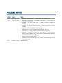
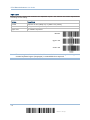
RELEASE NOTES
Version
Date
Notes
1.02
Nov. 29, 2010
Modified: Specifications — Temperature, power adaptor
1.01
Sep. 29, 2010
Modified: 2.3 Direct USB HID — change command 100005 to
100009
Modified: 2.4 Direct USB Virtual COM — change command 100004 to
100008
Modified: 3.13 GS1 DataBar (RSS Family)
New: 5.4.5 Pause Field Setting
1.00
May 12, 2010
Modified: Introduction, Symbologies Supported — add support of
more RSS symbologies
Modified: 3.13.2 GS1 DataBar Omnidirectional (RSS-14)
Modified: 3.13.3 GS1 DataBar Expanded (RSS Expanded)
Modified: 5 Applying Formats for Data Editing — add maximum
output length (4084 bytes; 2042 bytes if Multi-Barcode Mode or
Multi-Barcode Editor is in use)
Modified: 5.5 Configuring Format — Define Transmission Sequence
(add pause field)
Initial Release
CONTENTS
IMPORTANT NOTICES ...................................................................................................................... - 3 For USA .......................................................................................................................................... - 3 For Canada .................................................................................................................................... - 3 For Product with Laser .................................................................................................................. - 4 Safety Precautions ........................................................................................................................ - 4 Care & Maintenance ..................................................................................................................... - 4 RELEASE NOTES .............................................................................................................................. - 5 INTRODUCTION .................................................................................................................................... 1
Inside the Package............................................................................................................................ 2
Product Highlights ............................................................................................................................. 2
Symbologies Supported .................................................................................................................... 3
QUICK START ....................................................................................................................................... 5
Enter Configuration Mode................................................................................................................. 6
Exit Configuration Mode.................................................................................................................... 6
Default Settings................................................................................................................................. 7
Save User Settings as Defaults ................................................................................................... 7
Restore User Defaults.................................................................................................................. 7
Restore System Defaults ............................................................................................................. 7
Read a Setup Barcode ...................................................................................................................... 8
Configure Parameters.................................................................................................................. 8
List the Current Settings ............................................................................................................ 12
UNDERSTANDING THE BARCODE SCANNER .................................................................................... 15
1.1 Power......................................................................................................................................... 16
1.2 LED Indicator ............................................................................................................................ 16
1.2.1 Good Read LED ................................................................................................................ 16
1.2.2 Good Read LED Duration.................................................................................................17
1.3 Beeper ....................................................................................................................................... 18
1.3.1 Beeper Volume................................................................................................................. 18
1.3.2 Good Read Beep .............................................................................................................. 19
1.4 Vibrator...................................................................................................................................... 20
1.4.1 Good Read Vibrator..........................................................................................................20
1.4.2 Good Read Vibrator Duration ..........................................................................................20
1.5 Send “NR” to Host .................................................................................................................... 21
1.6 Scan Modes .............................................................................................................................. 22
1.6.1 Continuous Mode .............................................................................................................23
1.6.2 Test Mode .........................................................................................................................23
1.6.3 Laser Mode....................................................................................................................... 24
1.6.4 Auto Off Mode...................................................................................................................24
1.6.5 Auto Power Off Mode .......................................................................................................24
1704 Barcode Scanner User Guide
1.6.6 Alternate Mode.................................................................................................................25
1.6.7 Aiming Mode.....................................................................................................................25
1.6.8 Multi-Barcode Mode.........................................................................................................26
1.7 Scanning Timeout.....................................................................................................................27
1.8 Delay between Re-read ............................................................................................................ 28
1.9 Read Redundancy (1D) ............................................................................................................29
1.10 Addon Security for UPC/EAN Barcodes ................................................................................ 30
1.11 Negative Barcodes .................................................................................................................31
1.12 Fuzzy 1D Processing .............................................................................................................. 31
1.13 Operation Mode...................................................................................................................... 32
1.13.1 Decode Mode Settings ..................................................................................................33
1.13.2 Enter/Exit Image Mode..................................................................................................35
1.13.3 Image Mode Settings.....................................................................................................36
1.13.4 Enter/Exit Video Mode...................................................................................................40
1.13.5 Video Mode Settings...................................................................................................... 40
1.14 Imager Preferences................................................................................................................41
1.14.1 Image Enhancement .....................................................................................................41
1.14.2 Image Resolution ...........................................................................................................42
1.14.3 Image Cropping.............................................................................................................. 43
1.14.4 Image File Format ..........................................................................................................44
1.14.5 Bits per Pixel .................................................................................................................. 44
1.14.6 JPEG Image Options ...................................................................................................... 45
1.15 Signature Capture ..................................................................................................................46
1.15.1 Signature Capture File Format......................................................................................47
1.15.2 Signature Capture Bits per Pixel ................................................................................... 47
1.15.3 Signature Capture Width & Height ............................................................................... 48
1.15.4 Signature Capture JPEG Quality....................................................................................48
1.16 Cable Auto-Detect ..................................................................................................................49
SELECTING OUTPUT INTERFACE ....................................................................................................... 51
2.1 Keyboard Wedge ...................................................................................................................... 53
2.1.1 Activate Keyboard Wedge & Select Keyboard Type....................................................... 54
2.1.2 Keyboard Settings............................................................................................................ 55
2.1.3 Inter-Character Delay .......................................................................................................63
2.1.4 Inter-Function Delay......................................................................................................... 63
2.2 RS-232 ...................................................................................................................................... 64
2.2.1 Activate RS-232 Interface ............................................................................................... 64
2.2.2 Baud Rate.........................................................................................................................64
2.2.3 Data Bits ........................................................................................................................... 65
2.2.4 Parity ................................................................................................................................. 65
2.2.5 Stop Bit ............................................................................................................................. 65
2.2.6 Flow Control......................................................................................................................66
2.2.7 Inter-Character Delay .......................................................................................................67
2.2.8 Inter-Function Delay......................................................................................................... 67
2.2.9 ACK/NAK Timeout ............................................................................................................ 68
2.3 Direct USB HID.......................................................................................................................... 69
2.3.1 Activate USB HID & Select Keyboard Type .....................................................................69
2.3.2 Keyboard Settings............................................................................................................ 70
2.3.3 Inter-Function Delay......................................................................................................... 77
1704 Barcode Scanner User Guide
2.3.4 HID Character Transmit Mode.........................................................................................77
2.4 Direct USB Virtual COM ............................................................................................................ 78
2.4.1 Activate USB Virtual COM ................................................................................................78
2.4.2 Inter-Function Delay......................................................................................................... 78
2.4.3 ACK/NAK Timeout ............................................................................................................ 79
CHANGING SYMBOLOGY SETTINGS.................................................................................................. 81
3.1 Codabar..................................................................................................................................... 82
3.1.1 Start/Stop Transmission..................................................................................................82
3.1.2 CLSI Conversion ...............................................................................................................82
3.1.3 Code Length Qualification ...............................................................................................83
3.2 Code 25 – Industrial 25 ........................................................................................................... 84
3.2.1 Code Length Qualification ...............................................................................................85
3.3 Code 25 – Interleaved 25........................................................................................................86
3.3.1 Verify Check Digit ............................................................................................................. 86
3.3.2 Transmit Check Digit........................................................................................................86
3.3.3 Convert to EAN-13............................................................................................................87
3.3.4 Code Length Qualification ...............................................................................................88
3.4 Code 25 – Matrix 25 ................................................................................................................89
3.4.1 Verify Check Digit ............................................................................................................. 89
3.4.2 Transmit Check Digit........................................................................................................89
3.4.3 Code Length Qualification ...............................................................................................90
3.5 Code 25 – Chinese 25 .............................................................................................................91
3.6 Italian Pharmacode (Code 32)................................................................................................. 92
3.7 Code 39..................................................................................................................................... 93
3.7.1 Verify Check Digit ............................................................................................................. 93
3.7.2 Transmit Check Digit........................................................................................................93
3.7.3 Standard/Full ASCII Code 39 ..........................................................................................94
3.7.4 Code Length Qualification ...............................................................................................95
3.8 Trioptic Code 39 ....................................................................................................................... 96
3.9 Code 93..................................................................................................................................... 97
3.9.1 Code Length Qualification ...............................................................................................98
3.10 Code 128 ................................................................................................................................ 99
3.11 GS1-128 (EAN-128) .............................................................................................................100
3.11.1 Transmit Code ID .........................................................................................................100
3.11.2 Field Separator (GS Character)...................................................................................100
3.12 ISBT 128 ...............................................................................................................................101
3.12.1 ISBT Concatenation .....................................................................................................101
3.12.2 ISBT Concatenation Redundancy ...............................................................................102
3.13 GS1 DataBar (RSS Family) ..................................................................................................103
3.13.1 Select Code ID..............................................................................................................103
3.13.2 GS1 DataBar Omnidirectional (RSS-14).....................................................................104
3.13.3 GS1 DataBar Expanded (RSS Expanded)...................................................................105
3.13.4 GS1 DataBar Limited (RSS Limited) ...........................................................................106
3.13.5 Convert to UPC/EAN ....................................................................................................107
3.14 MSI ........................................................................................................................................108
3.14.1 Verify Check Digit .........................................................................................................108
3.14.2 Transmit Check Digit ...................................................................................................108
3.14.3 Code Length Qualification ...........................................................................................109
1704 Barcode Scanner User Guide
3.15 EAN-8 ....................................................................................................................................110
3.16 EAN-13 ..................................................................................................................................111
3.16.1 Convert to ISBN............................................................................................................112
3.16.2 Convert to ISSN............................................................................................................112
3.17 UCC Coupon Extended Code ...............................................................................................113
3.18 UPC-A.....................................................................................................................................114
3.18.1 Transmit System Number............................................................................................115
3.18.2 Transmit Check Digit ...................................................................................................115
3.19 UPC-E.....................................................................................................................................116
3.19.1 Select System Number ................................................................................................117
3.19.2 Convert to UPC-A..........................................................................................................117
3.19.3 Transmit System Number............................................................................................118
3.19.4 Transmit Check Digit ...................................................................................................118
3.20 Code 11 ................................................................................................................................119
3.20.1 Verify Check Digit .........................................................................................................119
3.20.2 Transmit Check Digit ...................................................................................................119
3.20.3 Code Length Qualification ...........................................................................................120
3.21 Composite Code ...................................................................................................................121
3.21.1 Composite CC-A/B .......................................................................................................121
3.21.2 Composite CC-C ...........................................................................................................121
3.21.3 Composite TLC-39 .......................................................................................................121
3.21.4 UPC Composite Mode..................................................................................................122
3.21.5 GS1-128 Emulation Mode for UCC/EAN Composite Codes......................................122
3.22 US Postal Code .....................................................................................................................123
3.22.1 US Postnet....................................................................................................................123
3.22.2 US Planet......................................................................................................................123
3.22.3 Transmit Check Digit ...................................................................................................123
3.23 UK Postal Code.....................................................................................................................124
3.23.1 UK Postal......................................................................................................................124
3.23.2 Transmit Check Digit ...................................................................................................124
3.24 More Postal Code .................................................................................................................125
3.24.1 Japan Postal.................................................................................................................125
3.24.2 Australian Postal ..........................................................................................................125
3.24.3 Dutch Postal.................................................................................................................125
3.24.4 USPS 4CB/One Code/Intelligent Mail ........................................................................125
3.24.5 UPU FICS Postal ...........................................................................................................126
3.25 2D Symbologies....................................................................................................................127
3.25.1 PDF417 ........................................................................................................................127
3.25.2 MicroPDF417 ...............................................................................................................127
3.25.3 Data Matrix...................................................................................................................128
3.25.4 Maxicode ......................................................................................................................129
3.25.5 QR Code........................................................................................................................129
3.25.6 MicroQR........................................................................................................................129
3.25.7 Aztec .............................................................................................................................129
3.26 Macro PDF ............................................................................................................................130
3.26.1 Transmit/Decode Mode ..............................................................................................130
3.26.2 Escape Characters.......................................................................................................131
3.26.3 Transmit Control Header .............................................................................................131
1704 Barcode Scanner User Guide
DEFINING OUTPUT FORMAT ............................................................................................................133
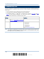
4.1 Letter Case..............................................................................................................................133
4.2 Character Substitution ...........................................................................................................134
4.2.1 Select a Set for Character Substituion .........................................................................135
4.2.2 Symbologies for Character Substitution (All 3 Sets) ....................................................136
4.3 Prefix/Suffix Code...................................................................................................................146
4.4 Code ID....................................................................................................................................147
4.4.1 Select Pre-defined Code ID............................................................................................147
4.4.2 Change Code ID..............................................................................................................150
4.4.3 Clear Code ID Settings ...................................................................................................153
4.5 Length Code............................................................................................................................154
4.6 Multi-Barcode Editor...............................................................................................................162
4.6.1 Edit a Concatenation of Barcodes ................................................................................163
4.6.2 Activate the Concatenation of Barcodes ......................................................................165
4.7 Removal of Special Character ...............................................................................................166
APPLYING FORMATS FOR DATA EDITING........................................................................................167
5.1 Activating Editing Formats .....................................................................................................168
5.1.1 Activate Editing Formats................................................................................................168
5.1.2 Exclusive Data Editing....................................................................................................169
5.2 How to Configure Editing Formats .........................................................................................170
5.2.1 Select Format to Configure............................................................................................171
5.2.2 Restore Default Format .................................................................................................172
5.3 Configuring Format — Define Data Criteria ...........................................................................173
5.3.1 Applicable Code Type.....................................................................................................173
5.3.2 Data Length ....................................................................................................................183
5.3.3 Matching String & Location ...........................................................................................184
5.4 Configuring Format — Define Data Field ...............................................................................185
5.4.1 Start Position ..................................................................................................................185
5.4.2 Field Adjustment ............................................................................................................185
5.4.3 Total Number of Fields...................................................................................................186
5.4.4 Field Settings..................................................................................................................187
5.4.5 Pause Field Setting ........................................................................................................193
5.5 Configuring Format — Define Transmission Sequence ........................................................194
5.6 Programming Examples .........................................................................................................196
5.6.1 Example I ........................................................................................................................196
5.6.2 Example II .......................................................................................................................197
SPECIFICATIONS ..............................................................................................................................199
FIRMWARE UPGRADE......................................................................................................................201
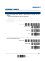
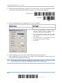
Upgrading 1704 Firmware............................................................................................................201
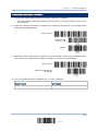
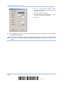
Upgrading USB Bridge Firmware ..................................................................................................203
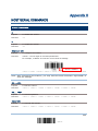
HOST SERIAL COMMANDS ..............................................................................................................205
Serial Commands ..........................................................................................................................205
Example .........................................................................................................................................206
1704 Barcode Scanner User Guide
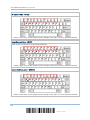
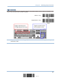
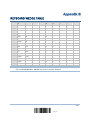
KEYBOARD WEDGE TABLE ..............................................................................................................207
Key Type & Status .........................................................................................................................208
Key Type....................................................................................................................................208
Key Status ................................................................................................................................208
Example .........................................................................................................................................209
NUMERAL SYSTEMS........................................................................................................................211
Decimal System.............................................................................................................................211
Hexadecimal System.....................................................................................................................212
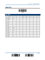
ASCII Table.....................................................................................................................................213
INTRODUCTION
CipherLab’s new industrial 1700 Series Barcode Scanners are specifically designed to
answer your demands for robust, versatile and high performance scanners. The tethered
handheld scanners are designed to help accelerate productivity while lowering the total
cost of ownership. Intensive data collection jobs are made easier with fast, accurate
barcode scanning in various working environments.
The 1704 scanner is our first scanner capable of reading a variety of 2D symbologies.
Owing to the rugged design, extremely low power consumption, and powerful decoding
capability, CipherLab Barcode Scanners are the best choice for the following applications
–
Receiving in Retail
Product labeling & Tracking
Shelf Product Replenishment
Mobile Point of Sale (POS)
Mobile Inventory Management
Order Picking & Staging
Work-In-Process Tracking
Material Flow Control
Transportation & Distribution
Warehousing
Asset Management
This manual contains information on operating the scanner and using its features. We
recommend you to keep one copy of the manual at hand for quick reference or
maintenance purposes. To avoid any improper disposal or operation, please read the
manual thoroughly before use.
Thank you for choosing CipherLab products!
1
Update
1704 Barcode Scanner User Guide
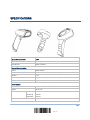
INSIDE THE PACKAGE
The items included in the package may be different, depending on your order. Rich
choices of output interfaces are available for you to enhance the total performance of the
scanner. Refer to product specifications.
Save the box and packaging material for future use in case you need to store or ship the
scanner.
Barcode Scanner: 1704
Product CD
Note: The CD-ROM includes this manual and Windows-based ScanMaster software for
configuration, as well as the USB Virtual COM driver.
PRODUCT HIGHLIGHTS
Ruggedized and built tough to survive drop test
Supports negative barcodes
Extremely low power consumption
Firmware upgradeable
Supports most popular barcode symbologies, including GS1-128 (EAN-128), GS1
DataBar (RSS), etc.
Supports a variety of 2D symbologies
Supports different scan modes, including Aiming Mode and Multi-Barcode ModeNote
User feedback via LED indicator, beeper and vibrator
Beeping tone and duration programmable for Good Read
Provides choices of output interfaces, including RS-232, Keyboard Wedge, and USB.
Programmable parameters include data output format, editing format, symbologies,
etc.
Supports OCX programming for signature capture in Decode Mode, Image Mode and
Video Mode
Note: (1) In any scan mode other than Multi-Barcode Mode, a barcode acceptable to
1704 can only contain data of 4084 bytes at most.
(2) 1704 supports different scan modes and signature capture in Decode Mode.
Two more operation modes are supported, which are Image Mode and Video
Mode. Image capture occurs in all modes of operation, and it requires software
applications to capture and download images to PC for decoding.
2
Enter Setup
Introduction
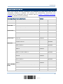
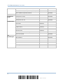
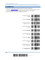
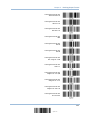
SYMBOLOGIES SUPPORTED
Most of the popular barcode symbologies are supported, as listed below. Each can be
individually enabled or disabled. The scanner will automatically discriminate and
recognize all the symbologies that are enabled. Refer to Chapter 3 Changing Symbology
Settings for details of each symbology.
Symbologies Supported: Enable/Disable
Default
Codabar
Enabled
Code 93
Enabled
MSI
Code 128
Disabled
Code 128
Enabled
GS1-128 (EAN-128)
Code 2 of 5
Code 3 of 9
EAN/UPC
ISBT 128
Enabled
Industrial 25
Enabled
Interleaved 25
Enabled
Matrix 25
Disabled
Chinese 25
Disabled
Code 39
Enabled
Italian Pharmacode
Disabled
Trioptic Code 39
Disabled
EAN-8
Enabled
EAN-8 Addon 2
Disabled
EAN-8 Addon 5
Disabled
EAN-13
Enabled
EAN-13 & UPC-A Addon 2
Disabled
EAN-13 & UPC-A Addon 5
Disabled
ISBN
Disabled
UPC-E0
Enabled
UPC-E1
Disabled
UPC-E Addon 2
Disabled
UPC-E Addon 5
Disabled
UPC-A
GS1 DataBar
(RSS)
Disabled
Enabled
GS1 DataBar Omnidirectional (RSS-14)
Disabled
GS1 DataBar Truncated
Disabled
GS1 DataBar Stacked
Disabled
GS1 DataBar Stacked Omnidirectional
Disabled
3
Update
1704 Barcode Scanner User Guide
GS1 DataBar Limited (RSS Limited)
Disabled
GS1 DataBar Expanded (RSS Expanded)
Disabled
GS1 DataBar Expanded Stacked
Disabled
Code 11
Composite
Code
Postal Code
2D
Symbologies
Disabled
Composite CC-A/B
Disabled
Composite CC-C
Disabled
Composite TLC-39
Disabled
US Postnet
Enabled
US Planet
Enabled
UK Postal
Enabled
Japan Postal
Enabled
Australian Postal
Enabled
Dutch Postal
Enabled
USPS 4CB/One Code/Intelligent Mail
Disabled
UPU FICS Postal
Disabled
PDF417
Enabled
MicroPDF417
Disabled
Data Matrix
Enabled
Maxicode
Enabled
QR Code
Enabled
MicroQR
Enabled
Aztec
Enabled
4
Enter Setup
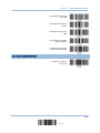
QUICK START
The configuration of the scanner can be done by reading the setup barcodes contained in
this manual or via the ScanMaster software.
This section describes the procedure of configuring the scanner by reading the setup
barcodes and provides some examples for demonstration.
Note: If RS-232 or USB Virtual COM is selected for output interface, the host can directly
send serial commands to configure the scanner.
For example, run HyperTerminal.exe and type the 6-digit command located under
each setup barcode. Refer to Appendix II Host Serial Commands.
5
Update
1704 Barcode Scanner User Guide
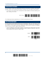
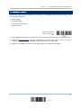
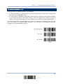
ENTER CONFIGURATION MODE
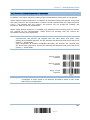
For the scanner to enter the configuration mode, you must have it read the "Enter Setup"
barcode, which can be located at the bottom of almost every even page of this manual.
The scanner will respond with six beeps and its LED indicator will become flashing red
after reading the barcode.
Enter Setup
For configuring scanner parameters, see “Read a Setup Barcode” below.
EXIT CONFIGURATION MODE
For the scanner to save settings and exit the configuration mode, you must have it read
the “Update” barcode, which can be located at the bottom of almost every odd page of
this manual. If you want to exit the configuration mode without saving any changes,
have the scanner read the “Abort” barcode instead.
Just like reading the “Enter Setup” barcode, the scanner will respond with six beeps
and its LED indicator will become flashing red after reading the barcode. Wait for a
few seconds for the scanner to restart itself.
Update
Abort
6
Enter Setup
Quick Start
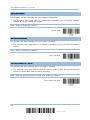
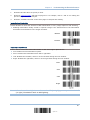
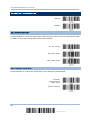
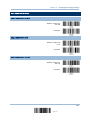
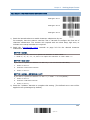
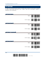
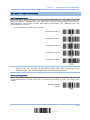
DEFAULT SETTINGS
SAVE USER SETTINGS AS DEFAULTS
For the scanner to keep the customized settings as user defaults, you must have it read
the “Save as User Defaults” barcode. This is a normal setup barcode, and the scanner will
respond with two beeps (low-high tone).
After reading the “Update” barcode, the current settings will be saved as user
defaults.
Save as User
Defaults
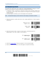
RESTORE USER DEFAULTS
For the scanner to restore the user defaults, which you have saved earlier, you must
have it read the “Restore User Defaults” barcode. This is a normal setup barcode, and the
scanner will respond with two beeps (low-high tone).
After reading the “Update” barcode, all the parameters of the scanner will return to
their customized values.
Restore User
Defaults
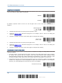
RESTORE SYSTEM DEFAULTS
For the scanner to restore the factory defaults, you must have it read the “Restore
System Defaults” barcode. This is a normal setup barcode, and the scanner will respond
with two beeps (low-high tone).
After reading the “Update” barcode, all the parameters of the scanner will return to
their default values.
Restore System
Defaults
Note: The system default value (if there is) for each setting is indicated by an asterisk
“*”.
7
Update
1704 Barcode Scanner User Guide
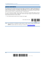
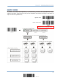
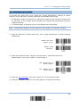
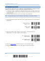
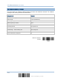
READ A SETUP BARCODE
CONFIGURE PARAMETERS
For most of the scanner parameters, only one read is required to set them to new values.
The scanner will respond with two beeps (low-high tone) when each parameter is set
successfully.
But for a number of special parameters, multiple reads are required to complete the
setting. In this case, the scanner will respond with a short beep to indicate it needs to
read more setup barcodes. These special parameters may require reading one or more
setup barcodes, such as
Numeric barcodes, say, for keyboard type, inter-character delay, length qualification
Hexadecimal barcodes, say, for character strings as prefix, suffix, etc.
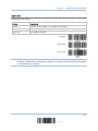
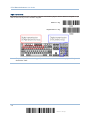
When “Keyboard Wedge” or “USB HID” is configured for interface, Key Type and Key
Status will then become applicable. You may decide whether or not to change key
status when “Normal Key” is selected for Key Type.
To complete the configuration of these special parameters, it requires reading the
“Validate” barcode, and the scanner will respond with two beeps (low-high tone) to
indicate the input values are validated.
8
Enter Setup
Quick Start
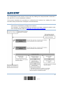
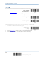
The example below shows how to save your settings as “User Default” so that you may
restore user defaults at a later time:
Steps
Action
User Feedback if Successful
1
Power on the scanner…
The scanner will respond with a long beep
(high tone) and its LED indicator will
become solid red and go off quickly.
2
Enter the Configuration Mode…
The scanner will respond with six beeps
(high-low tone repeats three times), and
its LED indicator will be flashing red.
3
Read a Setup barcode…
The scanner will respond with two beeps
(low-high tone) if reading a normal setup
barcode.
For example,
4
Exit the Configuration Mode…
Same as for Enter the Configuration Mode.
OR
5
The scanner will automatically restart itself…
Same as for Power on the scanner.
*
When any configuration error occurs...
The scanner will respond with one long
beep (low tone).
9
Update
1704 Barcode Scanner User Guide
The example below shows how to set numeric parameters:
Steps
Action
User Feedback if Successful
1
Power on the scanner...
The scanner will respond with a long beep
(high tone) and its LED indicator will
become solid red and go off quickly.
2
Enter the Configuration Mode…
The scanner will respond with six beeps
(high-low tone repeats three times), and
its LED indicator will become flashing red.
3
Read a Setup barcode...
The scanner will respond with two beeps
(low-high tone) if reading a normal setup
barcode.
For example,
Normal setup
barcode
Normal setup
barcode
The scanner will respond with one short
beep if reading a special setup barcode
such as “Max. Length”, indicating the
setup requires reading more barcodes.
Special setup
barcode
Read the “Decimal Value” barcode(s).
Decimal barcodes
Refer to
System”
Appendix
IV
“Decimal
The scanner will respond with two beeps
(low-high tone) when the input values are
validated.
4
Exit the Configuration Mode…
Same as for Enter the Configuration Mode.
OR
5
The scanner will automatically restart itself…
Same as for Power on the scanner.
10
Enter Setup
Quick Start
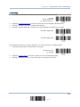
The example below shows how to set string parameters:
Steps
Action
User Feedback if Successful
1
Power on the scanner...
The scanner will respond with a long beep
(high tone) and its LED indicator will
become solid red and go off quickly.
2
Enter the Configuration Mode…
The scanner will respond with six beeps
(high-low tone repeats three times), and
its LED indicator will become flashing red.
3
Read a Setup barcode...
The scanner will respond with one short
beep if reading a special setup barcode
such as “Prefix Code”, indicating the setup
requires reading more barcodes.
For example,
Special setup
barcodes
When “Keyboard Wedge” or “USB HID” is
configured for interface, Key Type and Key
Status will then become applicable. You
may decide whether or not to change key
status when “Normal Key” is selected for
Key Type.
Refer to Appendix III
Read the “Hexadecimal Value” barcodes
for the desired character string. For
example, read “2” and “B” for the scanner
to prefix the character “+”.
Hexadecimal
barcodes
Refer to Appendix IV “Hexadecimal
System”
The scanner will respond with two beeps
(low-high tone) when the input values are
validated.
4
Exit the Configuration Mode…
Same as for Enter the Configuration Mode.
OR
5
The scanner will automatically restart itself…
Same as for Power on the scanner.
11
Update
1704 Barcode Scanner User Guide
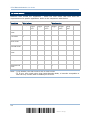
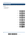
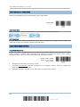
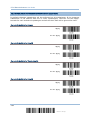
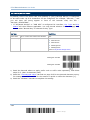
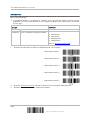
LIST THE CURRENT SETTINGS
The current settings of all scanner parameters can be sent to the host computer for user
inspection. The listing includes pages as shown below. You can select the page of interest
by having the scanner read the “List Page x” barcode. The scanner will respond with two
beeps (low-high tone) and send the selected page to the host immediately.
List settings regarding Firmware Version, Serial
Number, Interface, Buzzer, and Other Scanner
Parameters
List Page 1
List settings regarding Prefix, Suffix, and Length
Code Setting (1/2)
List Page 2
List settings regarding Prefix, Suffix, and Length
Code Setting (2/2)
List Page 3
List settings regarding Code ID
List Page 4
List settings regarding: Readable Symbologies
(1/2)
List Page 5
List settings regarding: Readable Symbologies
(2/2)
List Page 6
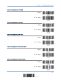
List settings regarding Symbology Parameters
(1/3)
List Page 7
List settings regarding Symbology Parameters
(2/3)
List Page 8
List settings regarding Symbology Parameters
(3/3)
List Page 9
List settings regarding Imager Parameters, as
well as Video and Signature Capture Parameters
List Page 10
12
Enter Setup
Quick Start
List settings regarding Editing Format 1
(1/2)
List Page 11
List settings regarding Editing Format 1
(2/2)
List Page 12
List settings regarding Editing Format 2
(1/2)
List Page 13
List settings regarding Editing Format 2
(2/2)
List Page 14
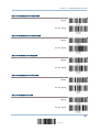
List settings regarding Editing Format 3
(1/2)
List Page 15
List settings regarding Editing Format 3
(2/2)
List Page 16
List settings regarding Editing Format 4
(1/2)
List Page 17
List settings regarding Editing Format 4
(2/2)
List Page 18
List settings regarding Editing Format 5
(1/2)
List Page 19
List settings regarding Editing Format 5
(2/2)
List Page 20
13
Update
1704 Barcode Scanner User Guide
14
Enter Setup
Chapter 1
UNDERSTANDING THE BARCODE SCANNER
This chapter explains the features and usage of the barcode scanner.
IN THIS CHAPTER
1.1 Power ......................................................................
1.2 LED Indicator ............................................................
1.3 Beeper .....................................................................
1.4 Vibrator....................................................................
1.5 Send “NR” to Host .....................................................
1.6 Scan Modes ..............................................................
1.7 Scanning Timeout ......................................................
1.8 Delay between Re-read...............................................
1.9 Read Redundancy (1D)...............................................
1.10 Addon Security for UPC/EAN Barcodes ........................
1.11 Negative Barcodes ...................................................
1.12 Fuzzy 1D Processing .................................................
1.13 Operation Mode .......................................................
1.14 Imager Preferences ..................................................
1.15 Signature Capture ....................................................
1.16 Cable Auto-Detect ....................................................
16
16
18
20
21
22
27
28
29
30
31
31
32
41
46
49
15
Update
1704 Barcode Scanner User Guide
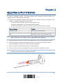
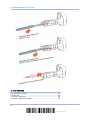
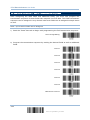
1.1 POWER
Connect the interface cable between the scanner and your computer.
If using the RS-232 cable, you must join the power supply cord to power up the
scanner.
The scanner will respond with one long beep (high tone) and its LED indicator will
become solid red and go off quickly.
1.2 LED INDICATOR
The dual-color LED on top of the scanner is used to provide user feedback. For example,
the LED becomes solid red and goes off quickly upon powering on. You may tell the
difference by the beeps – for example, you will hear a long beep of high tone when
powering on the scanner, and two beeps of high-low tone when RS-232/USB Virtual COM
connection fails.
Meaning
Scanner LED
Red, on-off
---
Power on, with one long beep (high tone, LED on for 1
second)
RS-232/USB Virtual COM connection fails, with two beeps
(high-low tone)
---
Green, on-off
Good Read, with one short beep (high tone) and beeper pitch and
duration programmable
Red, flashing
---
Configuration Mode (On/Off ratio 0.5 s: 0.5 s)
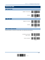
1.2.1 GOOD READ LED
*Enable
Good Read LED
Disable
Good Read LED
16
Enter Setup
Chapter 1
Understanding the Barcode Scanner
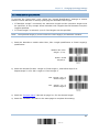
1.2.2 GOOD READ LED DURATION
By default, the Good Read LED stays on for 40 milliseconds. Specify a value, ranging
from 1 to 254 in units of 10 milliseconds.
Good Read LED
Time-out after
0.01~2.54 sec.
(*40 ms)
1) Read the barcode above to specify the time interval before the Good Read LED goes
off.
2) Read the “Decimal Value” barcode on page 211. For example, read “1” and “5” for the
LED to go off after 150 milliseconds.
3) Read the “Validate” barcode on the same page to complete this setting.
17
Update
1704 Barcode Scanner User Guide
1.3 BEEPER
The scanner has a buzzer to provide user feedback in various operating conditions.
Beeping
Meaning
One long beep, high tone
Power on, with red LED on (1 second) and off quickly
One short beep, high tone
Good Read, with green LED on-off quickly
Programmable, default to 4 KHz
Six short beeps
High-low tone repeats three times
Two beeps, low-high tone
Enter Configuration Mode, with red LED flashing
Exit Configuration Mode
Setup barcode read successfully
Abort or exit Image Mode/Video Mode/Signature
Capture
Two beeps, high-low tone
RS-232/USB Virtual COM connection fails (data saved in
buffer), with red LED on-off quickly
One short beep, high tone
More setup barcode required
One short beep, low tone
More barcodes required to complete the “output
sequence” requirements of Multi-Barcode Editor, with
green LED on-off quickly (Upon completion, same as
Good Read.)
One long beep, low tone
Configuration error (Wrong barcode…)
Two long beeps, high-low tone
Multi-Barcode Mode – Buffer full
1.3.1 BEEPER VOLUME
Mute
Minimum Volume
Medium Volume
*Maximum Volume
18
Enter Setup
Chapter 1
Understanding the Barcode Scanner
1.3.2 GOOD READ BEEP
Frequency
8 kHz
*4 kHz
2 kHz
1 kHz
Duration
*Shortest
Shorter
Longer
Longest
19
Update
1704 Barcode Scanner User Guide
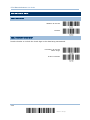
1.4 VIBRATOR
1.4.1 GOOD READ VIBRATOR
Enable
Good Read Vibrator
*Disable
Good Read Vibrator
1.4.2 GOOD READ VIBRATOR DURATION
By default, the Good Read Vibration stays on for 1 second. Specify a value, ranging from
1 to 254 in units of 100 milliseconds.
Good Read Vibrator
Time-out after
0.1~25.4 sec.
(*1 s)
1) Read the barcode above to specify the time interval before the Good Read Vibrator
goes off.
2) Read the “Decimal Value” barcode on page 211. For example, read “1” and “5” for the
vibrator to go off after 1.5 seconds.
3) Read the “Validate” barcode on the same page to complete this setting.
20
Enter Setup
Chapter 1
Understanding the Barcode Scanner
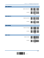
1.5 SEND “NR” TO HOST
You may have the scanner send the “NR” string to the host to notify the No Read event.
Enable
*Disable
21
Update
1704 Barcode Scanner User Guide
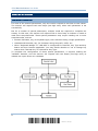
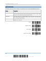
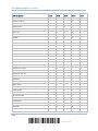
1.6 SCAN MODES
Different scan modes are supported – select the scan mode that best suits the
requirements of a specific application. Refer to the comparison table below.
Scan Mode
Start to Scan
Always
Press
trigger
once
Stop Scanning
Hold
trigger
Press
trigger
twice
Release
trigger
Press
trigger
once
Barcode
being
read
Timeout
Continuous
mode
Test mode
Laser mode
Auto Off mode
Auto Power Off
mode
Alternate mode
Aiming mode
Multi-Barcode
mode
Note: (1) By default, the scan mode is set to Laser mode.
(2) In any scan mode other than Multi-Barcode Mode, a barcode acceptable to
1704 can only contain data of 4084 bytes at most.
22
Enter Setup
Chapter 1
Understanding the Barcode Scanner
1.6.1 CONTINUOUS MODE
The scanner is always scanning.
After a successful decoding, the removal of barcode is required. It is not allowed to
proceed to decode until the decoding delay time has passed.
To decode the same barcode repeatedly, move away the barcode and put it back
again and again for scanning.
Note: Refer to “Delay between Re-read”.
Continuous Mode
Decoding Delay
Set the time interval between each decoding.
*Disable
0.5 sec
1 sec
2 sec
1.6.2 TEST MODE
The scanner is always scanning.
Capable of decoding the same barcode repeatedly without removing it, for testing
purpose.
Test Mode
23
Update
1704 Barcode Scanner User Guide
1.6.3 LASER MODE
The scanner will start scanning once the trigger is held down.
The scanning won't stop until (1) a barcode is decoded, (2) the pre-set timeout
expires, or (3) you release the trigger.
Note: Refer to “Scanning Timeout”.
*Laser Mode
1.6.4 AUTO OFF MODE
The scanner will start scanning once the trigger is pressed.
The scanning won't stop until (1) a barcode is decoded, and (2) the pre-set timeout
expires.
Note: Refer to “Scanning Timeout”.
Auto Off Mode
1.6.5 AUTO POWER OFF MODE
The scanner will start scanning once the trigger is pressed.
The scanning won't stop until the pre-set timeout expires, and, the pre-set timeout
period re-counts after each successful decoding.
Note: Refer to “Delay between Re-read” and “Scanning Timeout”.
Auto Power Off Mode
24
Enter Setup
Chapter 1
Understanding the Barcode Scanner
1.6.6 ALTERNATE MODE
The scanner will start scanning once the trigger is pressed
The scanning won't stop until you press the trigger again.
Alternate Mode
1.6.7 AIMING MODE
The scanner will aim at a barcode once the trigger is pressed, and start scanning when
the trigger is pressed again within one second.
The scanning won't stop until (1) a barcode is decoded, and (2) the pre-set timeout
expires.
Aiming Mode
Aiming Timeout
You can limit the aiming time interval (1~15). By default, the scanner time-out is set to 1 second.
Aiming Time-out
after 1~15 sec.
(*1)
1.
Read the barcode above to specify the time interval before aiming ends. (It is set to 1 by
default.)
2.
Read the “Decimal Value” barcode on page 211. For example, read “1” and “0” for the scanner
to automatically shut down after being idle for 10 seconds.
3.
Read the “Validate” barcode on the same page to complete this setting.
25
Update
1704 Barcode Scanner User Guide
1.6.8 MULTI-BARCODE MODE
The scanner will be scanning as long as the trigger is held down, capable of decoding one
single barcode, as well as a multiple unique barcodes one at a time. While decoding a
bunch of unique barcodes, if a barcode is decoded twice, its subsequent decoding will be
ignored and the scanner is expecting another unique barcode.
For 1704 to decode multiple unique barcodes, the maximum output data length of all the
barcodes is 2042 bytes after configuration. When the output length exceeds 2042 bytes,
Multi-Barcode Mode will not take effect.
The scanning won't stop until you release the trigger.
Multi-Barcode Mode
Note: (1) A barcode is considered unique when its Code Type or data is different from
others.
(2) Multi-Barcode Mode has nothing to do with the Multi-Barcode Editor.
26
Enter Setup
Chapter 1
Understanding the Barcode Scanner
1.7 SCANNING TIMEOUT
Specify the scanning time interval (1~254 sec.; 0= Disable) when the scan mode is set
to any of the following –
Laser mode
Auto Off mode
Auto Power Off mode
Aiming mode
Scanner Time-out
after 0~254 sec.
(*10)
1) Read the barcode above to specify the time interval before the scan engine times out.
2) Read the “Decimal Value” barcode on page 211. For example, read “1” and “5” for the
scanner to automatically shut down after being idle for 15 seconds.
3) Read the “Validate” barcode on the same page to complete this setting.
27
Update
1704 Barcode Scanner User Guide
1.8 DELAY BETWEEN RE-READ
This is also referred to as the “Blocking Time”, which is used to prevent the scanner from
accidentally reading the same barcode twice when the scan mode is set to any of the
following –
Continuous mode
Auto Power Off mode
Alternate mode
100 ms
200 ms
*400 ms
800 ms
1 sec
2 sec
3 sec
5 sec
28
Enter Setup
Chapter 1
Understanding the Barcode Scanner
1.9 READ REDUNDANCY (1D)
Select the level of reading security. For example,
If "No Redundancy" is selected, one successful decoding will make the reading valid
and induce the "READER Event".
If "Two Times" is selected, it will take a total of three consecutive successful decoding
of the same barcode to make the reading valid. The higher the reading security is
(that is, the more redundancy the user selects), the slower the reading speed gets.
It is obvious that the more redundancy you select, the higher the reading security is, and
thus, the slower the reading speed becomes. You will have to compromise between
reading security and decoding speed.
*No Redundancy
One Time
Two Times
29
Update
1704 Barcode Scanner User Guide
1.10 ADDON SECURITY FOR UPC/EAN BARCODES
The scanner is capable of decoding a mix of UPC/EAN barcodes with and without addons.
The read redundancy (2~30 times) allows changing the number of times to decode a
UPC/EAN barcode before transmission. The more redundancy you select, the higher the
reading security is, and thus, the slower the reading speed becomes. You will have to
compromise between reading security and decoding speed.
Note: UPC/EAN Addon 2 and Addon 5 must be enabled individually for this setting to
take effect.
Addon Security Level
(*2~30)
1) Read the barcode above to specify the read redundancy for UPC/EAN barcodes. (It is
set to 2 by default.)
2) Read the “Decimal Value” barcode on page 211. For example, read “1” and “2” for the
scanner to re-read the barcode for 12 times.
3) Read the “Validate” barcode on the same page to complete this setting.
30
Enter Setup
Chapter 1
Understanding the Barcode Scanner
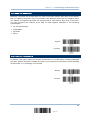
1.11 NEGATIVE BARCODES
Normally, barcodes are printed with the color of the bars darker than that of the spaces.
But for negative barcodes, they are printed in the opposite sense just like negative films.
The spaces of negative barcodes are printed with a color darker than that of the bars.
You can configure the scanner to be able to read negative barcodes in the following
symbologies:
All 1D symbologies
Data Matrix
QR Code
Aztec
Enable
*Disable
1.12 FUZZY 1D PROCESSING
By default, this option optimizes decode performance on 1D barcodes, including damaged
and poor quality barcodes. Disable this only if you experience time delays when decoding
2D barcodes, or in detecting a no decode.
*Enable
Disable
31
Update
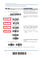
1704 Barcode Scanner User Guide
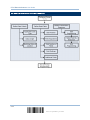
1.13 OPERATION MODE
For 1704, it supports different scan modes and signature capture in Decode Mode. Two
more operation modes are supported, which are Image Mode and Video Mode. Image
capture occurs in all modes of operation, and it requires software applications, such as
ScanMaster, to capture and download images to PC for decoding. Please refer to separate
manual for OCX programming support.
For Image Mode, Video Mode or signature capture in Decode Mode, the output interface
must be RS-232 or USB Virtual COM. Both active and passive modes are supported.
Active Mode: Application on the host will send command to instruct the scanner to
stay in a specific operation mode (Image Mode/Video Mode/Signature Capture) and
wait for image data. Press the trigger to capture and send an image.
Passive Mode: First, it requires the scanner to read the setup barcodes for the desired
operation — signature Capture, Image Mode or Video Mode. Then, it will passively
wait for image data. Press the trigger to capture and send an image.
Signature Capture, Image Mode or Video Mode
Have the scanner read the setup barcodes in a separate but complete sequence. For example,
the following sequence will allow the scanner to enter Image Mode:
But the sequence below will allow you to configure settings only:
Refer to 1.13.2 Enter/Exit Image Mode.
Refer to 1.13.4 Enter/Exit Video Mode.
Refer to 1.15 Signature Capture.
32
Enter Setup
Chapter 1
Understanding the Barcode Scanner
1.13.1 DECODE MODE SETTINGS
By default, this is the normal operation mode. The decoder attempts to locate and
decode any barcode within its field of view upon a trigger event. Refer to 1.6 Scan
Modes.
Decode Aiming Pattern
Decide whether to allow the decoder to project the aiming pattern during a barcode capture.
*Enable
Disable
Decoding Illumination
Decide whether to cause the decoder to flash illumination on every image capture to aid decoding.
Enabling illumination usually results in superior images. The effectiveness of the illumination
decreases as the distance to the target increases.
*Enable
Disable
Illumination Bank Control
This is used to control the illumination banks on the scan engine. Options are –
Full: Enables the full illumination system.
Auto: Switches the illumination from left to right bank.
Left: Enables the left bank, which is on the left when facing the scan window.
Right: Enables the right bank, which is on the right when facing the scan window.
*Full
Auto
33
Update
1704 Barcode Scanner User Guide
Left
Right
Note: When the ambient light is too dim on the left (or right), you may enable the left
(or right) illumination bank to add lighting.
Decoding Autoexposure
Decide whether to manually specify the gain and exposure time (only recommended for advanced
users with difficult image capture situations).
*Enable
Disable
By default, exposure value is set to 10 ms and gain value is set to 50 when autoexposure is
disabled.
Fixed Exposure
in 100 μs
2~5000 (*100)
1.
Read the barcode above to specify a fixed exposure value.
2.
Read the “Decimal Value” barcode on page 211. For example, read “1” and “5” for setting the
exposure value to 1.5 ms.
3.
Read the “Validate” barcode on the same page to complete this setting
Fixed Gain
1~100 (*50)
4.
Read the barcode above to specify a fixed gain value.
5.
Read the “Decimal Value” barcode on page 211. For example, read “3” and “0” for setting the
gain value to 30.
6.
Read the “Validate” barcode on the same page to complete this setting.
34
Enter Setup
Chapter 1
Understanding the Barcode Scanner
1.13.2 ENTER/EXIT IMAGE MODE
Use Image Mode to capture a high-quality image and transmit it to the host. Read the
barcode below to temporarily enter this mode.
Image Mode
Enter Image Mode
Have the scanner read the setup barcodes in a separate but complete sequence:
Exit Image Mode
Once the software application finishes the task of receiving an image, the scanner returns to
Decode Mode.
If a trigger event is not activated within the Image Mode Timeout period, the decoder returns
to Decode Mode.
35
Update
1704 Barcode Scanner User Guide
1.13.3 IMAGE MODE SETTINGS
Image Mode Timeout
Set the amount of time the decoder remains in Image Mode. The decoder exits Image Mode upon a
trigger event, or when the Image Mode Timeout elapses. By default, the time-out value is set to 0
which represents 30 seconds. Values increment by 30. For example, 1 = 60 seconds, 2 = 90
seconds, etc.
Image Mode Time-out
after 30~ sec.
(*0)
1.
Read the barcode above to specify the time interval before returning to Decode Mode. (It is
set to 0 by default.)
2.
Read the “Decimal Value” barcode on page 211. For example, read “5” for the scanner to
automatically shut down after being idle for 180 seconds.
3.
Read the “Validate” barcode on the same page to complete this setting.
Image Aiming Pattern
Decide whether to allow the decoder to project the aiming pattern in Image Mode.
*Enable
Disable
Video View Finder
Decide whether to enable Image Mode with View Finder, which the decoder behaves as a video
camera until a trigger event is activated.
Enable
*Disable
Select the number of 100-byte blocks. Values range from 800 to 3000 bytes. Selecting a smaller
value transmits more frames per second; selecting a larger value increases video quality.
Video View Finder
Image Size in 100
bytes 8~30 (*17)
36
Enter Setup
Chapter 1
Understanding the Barcode Scanner
1.
Read the barcode above to specify a value.
2.
Read the “Decimal Value” barcode on page 211. For example, read “1” and “5” for setting the
preview image size to 1500 bytes.
3.
Read the “Validate” barcode on the same page to complete this setting.
Image Capture Illumination
Decide whether to cause the decoder to flash illumination on every image capture to aid decoding.
Enabling illumination usually results in superior images. The effectiveness of the illumination
decreases as the distance to the target increases.
*Enable
Disable
Illumination Bank Control
This is used to control the illumination banks on the scan engine. Options are –
Full: Enables the full illumination system.
Auto: Switches the illumination from left to right bank.
Left: Enables the left bank, which is on the left when facing the scan window.
Right: Enables the right bank, which is on the right when facing the scan window.
*Full
Auto
Left
Right
Note: When the ambient light is too dim on the left (or right), you may enable the left
(or right) illumination bank to add lighting.
37
Update
1704 Barcode Scanner User Guide
Image Capture Autoexposure
Decide whether to manually specify the gain and exposure time (only recommended for advanced
users with difficult image capture situations).
*Enable
Disable
By default, exposure value is set to 10 ms and gain value is set to 50 when autoexposure is
disabled.
Fixed Exposure
in 100 μs
2~5000 (*100)
1.
Read the barcode above to specify a fixed exposure value.
2.
Read the “Decimal Value” barcode on page 211. For example, read “1” and “5” for setting the
exposure value to 1.5 ms.
3.
Read the “Validate” barcode on the same page to complete this setting
Fixed Gain
1~100 (*50)
4.
Read the barcode above to specify a fixed gain value.
5.
Read the “Decimal Value” barcode on page 211. For example, read “3” and “0” for setting the
gain value to 30.
6.
Read the “Validate” barcode on the same page to complete this setting.
Gain/Exposure Priority for Image Mode
Alter the decoder’s gain/exposure priority when it acquires an image in Image Mode with auto
exposure enabled.
Low Gain Priority: The decoder favors longer exposure time rather than higher gain to capture
an image. This ensures that the image is less noisy and produces fewer artifacts during
post-processing activities like image enhancement (sharpening). This mode is ideal for fixed
mount/fixed object image capture since the image acquired is susceptible to motion blur.
Low Exposure Priority: The decoder favors higher gain over exposure to capture an image. This
results in an image that is less susceptible to motion blur at the expense of noise artifacts.
However, for most applications, the amount of noise is acceptable.
Low Gain Priority
38
Enter Setup
Chapter 1
Understanding the Barcode Scanner
*Low Exposure
Priority
Image Brightness (Target White)
Decide whether to set the Target White value when using autoexposure. White and black are
defined as 255 decimal and 0, respectively. If the value is 180, which is the factory default, the
white level of the image is ~180.
Image Brightness
1~240 (*180)
1.
Read the barcode above to specify a value.
2.
Read the “Decimal Value” barcode on page 211. For example, read “1”, “2” and “0” for a value
of 120.
3.
Read the “Validate” barcode on the same page to complete this setting
39
Update
1704 Barcode Scanner User Guide
1.13.4 ENTER/EXIT VIDEO MODE
Read the barcode below to temporarily enter this mode.
Video Mode
Enter Video Mode
Have the scanner read the setup barcodes in a separate but complete sequence:
Exit Video Mode
In Video Mode, the decoder behaves as a video camera as long as the trigger is active. When you
release the trigger, the decoder returns to Decode Mode.
1.13.5 VIDEO MODE SETTINGS
Target Video Frame Size
Select the number of 100-byte blocks to transmit per second. Values range from 800 to 3300
bytes. Selecting a smaller value transmits more frames per second but reduces video quality;
selecting a larger value increases video quality but slows transmission.
Target Video Frame
Size in 100 bytes
8~33 (*22)
1.
Read the barcode above to specify a value.
2.
Read the “Decimal Value” barcode on page 211. For example, read “2” and “0” for setting the
video frame size to 2000 bytes.
3.
Read the “Validate” barcode on the same page to complete this setting
40
Enter Setup
Chapter 1
Understanding the Barcode Scanner
1.14 IMAGER PREFERENCES
These settings are for Image Mode.
1.14.1 IMAGE ENHANCEMENT
This feature uses a combination of edge sharpening and contrast enhancement to
produce an image that is visually pleasing.
*Off
Low
Medium
High
41
Update
1704 Barcode Scanner User Guide
1.14.2 IMAGE RESOLUTION
This feature alters image resolution before compression. Multiple pixels are combined to
one pixel, resulting in a smaller image containing the original content with reduced
resolution. Options are –
Full: 1280 x 1024 (uncropped image size)
1/2: 640 x 512 (uncropped image size)
1/4: 320 x 160 (uncropped image size)
*Full Resolution
1/2 Resolution
1/4 Resolution
42
Enter Setup
Chapter 1
Understanding the Barcode Scanner
1.14.3 IMAGE CROPPING
This is used to crop a captured image.
Disable Image Cropping: Present the full 1280 x 1024 pixels.
Enable Image Cropping: Crop the image to the pixel addresses specified.
Enable
*Disable
Note: The scanner has a cropping resolution of 4 pixels. Setting the cropping area to less
than 3 pixels transfers the entire image.
Crop to Pixel Address
For image cropping, set the pixel addresses from (0,0) to (1279, 1023) to crop to. Columns are
numbered from 0 to 1279, rows from 0 to 1023. Specify four values for Top, Left, Bottom, and
Right, where Top and Bottom correspond to row pixel addresses, and Left and Right correspond to
column pixel addresses. For example, for a 4 row x 8 column image in the extreme bottom-right
section of the image, set the following values:
Top = 1020, Bottom = 1023, Left = 1272, Right = 1279
Top (0~1023)
Left (0~1279)
Bottom (0~1023)
Right (0~1279)
1.
Read the barcode above one at a time to specify its value.
2.
Read the “Decimal Value” barcode on page 211. For example, read “4”, “7” and “6” for a value
of 476.
3.
Read the “Validate” barcode on the same page to complete this setting
43
Update
1704 Barcode Scanner User Guide
1.14.4 IMAGE FILE FORMAT
Select an image format for storing captured images.
*JPEG
BMP
TIFF
1.14.5 BITS PER PIXEL
Select the number of significant bits per pixel (BPP) to use when capturing an image.
Select 1 BPP for a black and white image, 4 BPP to assign 1 of 16 levels of grey to each
pixel, or 8 BPP to assign 1 of 256 levels of grey to each pixel.
Note: The decoder ignores these settings for JPEG files, which always use 8 BPP.
1 BPP
4 BPP
*8 BPP
44
Enter Setup
Chapter 1
Understanding the Barcode Scanner
1.14.6 JPEG IMAGE OPTIONS
Optimize JPEG images for either size or quality.
*JPEG Quality
Selector
JPEG Size Selector
JPEG Target File Size
Define the target JPEG file size in terms of 1 Kilobytes (1024 bytes). By default, it is set to 160
Kilobytes.
JPEG Target File Size
5~600 (*160)
1.
Read the barcode above to specify a value.
2.
Read the “Decimal Value” barcode on page 211. For example, read “1”, “2” and “0” for a value
of 120.
3.
Read the “Validate” barcode on the same page to complete this setting
JPEG Quality Value
If you selected JPEG Quality Selector, specify the JPEG quality value. By default, it is set to 65.
JPEG Quality Value
5~100 (*65)
1.
Read the barcode above to specify a value.
2.
Read the “Decimal Value” barcode on page 211. For example, read “5” and “0” for a value of
50.
3.
Read the “Validate” barcode on the same page to complete this setting
45
Update
1704 Barcode Scanner User Guide
1.15 SIGNATURE CAPTURE
A signature capture barcode is a special-purpose symbology, which delineate a signature
capture area in a document with a machine-readable format. The recognition pattern is
variable so it can optionally provide an index to various signatures. The region inside the
barcode pattern is considered the signature capture area.
Decide whether to allow the decoder to capture signature in Decode Mode.
Enable Signature
Capture
*Disable Signature
Capture
Enable Signature Capture
Have the scanner read the setup barcodes in a separate but complete sequence:
Disable Signature Capture
Have the scanner read only one setup barcode to complete the setting:
46
Enter Setup
Chapter 1
Understanding the Barcode Scanner
1.15.1 SIGNATURE CAPTURE FILE FORMAT
Select an image format for storing captured signatures.
*JPEG
BMP
TIFF
1.15.2 SIGNATURE CAPTURE BITS PER PIXEL
Select the number of significant bits per pixel (BPP) to use when capturing a signature.
Select 1 BPP for a black and white image, 4 BPP to assign 1 of 16 levels of grey to each
pixel, or 8 BPP to assign 1 of 256 levels of grey to each pixel.
Note: The decoder ignores these settings for JPEG files, which always use 8 BPP.
1 BPP
4 BPP
*8 BPP
47
Update
1704 Barcode Scanner User Guide
1.15.3 SIGNATURE CAPTURE WIDTH & HEIGHT
The aspect ratio of the Signature Capture Width and Signature Capture Height
parameters must match that of the signature capture area. For example, a 4 x 1 inch
signature capture area would require a 4 to 1 aspect ratio of width to height.
Signature Capture
Width 1~640 (*400)
Signature Capture
Height 1~480 (*100)
1) Read the barcode above one at a time to specify its value.
2) Read the “Decimal Value” barcode on page 211. For example, read “4”, “8” and “0”
for a value of 480.
3) Read the “Validate” barcode on the same page to complete this setting.
1.15.4 SIGNATURE CAPTURE JPEG QUALITY
Specify the JPEG quality value. By default, it is set to 65.
JPEG Quality Value
5~100 (*65)
1) Read the barcode above to specify a value.
2) Read the “Decimal Value” barcode on page 211. For example, read “5” and “0” for a
value of 50.
3) Read the “Validate” barcode on the same page to complete this setting.
48
Enter Setup
Chapter 1
Understanding the Barcode Scanner
1.16 CABLE AUTO-DETECT
Find the interface cable provided inside the package. Connect it to the scanner. The
scanner will detect the interface automatically. Refer to Chapter 2 — Selecting Output
Interface.
Cable Auto-Detect
Defaults
Keyboard Wedge
PCAT (US) for keyboard type
RS-232
115200 bps, 8 bits, No parity, 1 stop bit
USB
USB HID and PCAT (US) for keyboard type
Note: If “USB Virtual COM” is desired, have the scanner read the setup barcodes.
*Enable
Disable
49
Update
1704 Barcode Scanner User Guide
50
Enter Setup
Chapter 2
SELECTING OUTPUT INTERFACE
In order to establish a proper connection between your computer and the scanner, we
suggest that you follow these instructions –
1) Connect the provided interface cable between the scanner and your computer. The
scanner is capable of detecting the interface.
If using the RS-232 cable, join the power supply cord.
If using the USB cable, it is set to USB HID by default.
If “USB Virtual COM” is desired, have the scanner read the setup barcodes.
Cable Auto-Detect
Defaults
Keyboard Wedge
PCAT (US) for keyboard type
RS-232
115200 bps, 8 bits, No parity, 1 stop bit
USB
USB HID and PCAT (US) for keyboard type
Note: Please make sure the cable you are using supports auto-detection. Check whether
there is a sticker on the cable, stating “Cable Detection Supported”.
2) Have the scanner read the “Enter Setup” barcode to enter the configuration mode.
3) Have the scanner read the associated barcodes to activate the desired interface.
See the following sections for output interfaces supported.
4) Have the scanner read the barcodes for related settings.
5) Have the scanner read the “Update” barcode to exit the configuration mode.
Note: For signature capture in Decode Mode, Image Mode and Video Mode, the output
interface must be RS-232 or USB Virtual COM.
51
Update
1704 Barcode Scanner User Guide
IN THIS CHAPTER
2.1
2.2
2.3
2.4
Keyboard Wedge .......................................................
RS-232 ....................................................................
Direct USB HID..........................................................
Direct USB Virtual COM...............................................
53
64
69
78
52
Enter Setup
Chapter 2
Selecting Output Interface
2.1 KEYBOARD WEDGE
The Y cable allows you to connect the scanner to the keyboard input port of PC and you
may join the keyboard as well. The scanned data will be transmitted to the host keyboard
port as if it is manually entered via the keyboard.
Keyboard Wedge Settings
Defaults
Keyboard Type
PCAT (US)
Alphabets Layout
Normal
Digits Layout
Normal
Capital Lock Type
Normal
Capital Lock State
Off
Alphabets Transmission
Case-sensitive
Digits Transmission
Alphanumeric keypad
Alternate Composing
No
Laptop Support
Disable
Inter-Character Delay
0 (ms)
Inter-Function Delay
0 (ms)
53
Update
1704 Barcode Scanner User Guide
2.1.1 ACTIVATE KEYBOARD WEDGE & SELECT KEYBOARD TYPE
When Keyboard Wedge interface is activated, you will have to select a keyboard type to
complete this setting.
Activate Keyboard
Wedge & Select
Keyboard Type…
1) Read this barcode above to activate Keyboard Wedge and select a keyboard type.
2) Read the “Decimal Value” barcode on page 211. Refer to the table below for the
number of desired keyboard type.
3) Read the “Validate” barcode on the same page to complete this setting.
Keyboard Type
By default, the keyboard type is set to PCAT (US). The following keyboard types are supported –
No.
Keyboard Type
No.
Keyboard Type
1
PCAT (US)
16
PS55 001-2
2
PCAT (French)
17
PS55 001-82
3
PCAT (German)
18
PS55 001-3
4
PCAT (Italian)
19
PS55 001-8A
5
PCAT (Swedish)
20
PS55 002-1, 003-1
6
PCAT (Norwegian)
21
PS55 002-81, 003-81
7
PCAT (UK)
22
PS55 002-2, 003-2
8
PCAT (Belgium)
23
PS55 002-82, 003-82
9
PCAT (Spanish)
24
PS55 002-3, 003-3
10
PCAT (Portuguese)
25
PS55 002-8A, 003-8A
11
PS55 A01-1
26
IBM 3477 Type 4 (Japanese)
12
PS55 A01-2 (Japanese)
27
PS2-30
13
PS55 A01-3
28
IBM 34XX/319X, Memorex Telex 122 Keys
14
PS55 001-1
29
User-defined table
15
PS55 001-81
30
PCAT (Turkish)
54
Enter Setup
Chapter 2
Selecting Output Interface
2.1.2 KEYBOARD SETTINGS
Alphabets Layout
Digits Layout
Capital Lock Type
Capital Lock Setting
Alphabets Transmission
Digits Transmission
Alternate Composing
Laptop Support
Alphabets Layout
By default, the alphabets layout is set to normal mode, also known as the standard English layout.
Select French or German keyboard layout if necessary. The scanner will make adjustments when
sending the "A", "Q", "W", "Z", "Y", and "M" characters according to this setting.
*Normal
AZERTY
QWERTZ
Note: This setting only works when the keyboard type selected is US keyboard, such as
PCAT (US). The Alphabets Layout and Digits Layout setting must match your
keyboard.
55
Update
1704 Barcode Scanner User Guide
US Keyboard Style – Normal
QWERTY layout, which is normally used in western countries.
Select “Lower Row” for the “Digits Layout” setting for the upper row is for special characters.
French Keyboard Style – AZERTY
French layout; see below for French Keyboard Style.
Select “Upper Row” for the “Digits Layout” setting for the lower row is for special characters.
German Keyboard Layout – QWERTZ
German layout; see below for German Keyboard Style.
Select “Lower Row” for the “Digits Layout” setting for the upper row is for special characters.
56
Enter Setup
Chapter 2
Selecting Output Interface
Digits Layout
Select a proper layout that matches the alphabets layout. The scanner will make adjustments
according to this setting.
Options
Description
Normal
Depends on the [Shift] key or [Shift Lock] setting
Lower Row
For QWERTY or QWERTZ keyboard
Upper Row
For AZERTY keyboard
*Normal
Upper Row
Lower Row
Note: This setting is meant to be used with the Alphabets Layout; and perhaps with the
Character Substitution setting when support to certain keyboard types (languages)
is unavailable but required.
57
Update
1704 Barcode Scanner User Guide
Capital Lock Type & Setting
In order to send the alphabets with correct case, the scanner needs to know the status of Caps
Lock on the keyboard. Incorrect settings may result in reversed case of the alphabets being
transmitted.
Cap Lock Type
Description
Normal
Normal type
Capital Lock
When enabled, the keys of alphabetic characters will be interpreted as
capital letters. However, this does not affect the number or punctuation
keys.
Shift Lock
When enabled, the keys of alphabetic characters will be interpreted as
capital letters. In addition, this affects the number or punctuation keys.
*Normal
Shift Lock
Capital Lock
Capital Lock State
Description
Capital Lock OFF
Assuming that the status of Caps Lock on the keyboard is OFF,
transmitted characters are exactly the same as in the barcode (when
"case-sensitive" is selected for Alphabets Transmission).
Capital Lock ON
Assuming that the status of Caps Lock on the keyboard is ON, transmitted
characters are exactly the same as in the barcode (when "case-sensitive"
is selected for Alphabets Transmission).
Auto Detection
Refer to the Capital Lock Type above.
The scanner will automatically detect the status of Caps Lock on the
keyboard before data is transmitted; transmitted characters are exactly
the same as in the barcode (when "case-sensitive" is selected for
Alphabets Transmission).
Auto Detect
Capital Lock ON
58
Enter Setup
Chapter 2
Selecting Output Interface
*Capital Lock OFF
59
Update
1704 Barcode Scanner User Guide
Alphabets Transmission
By default, the alphabets transmission is case-sensitive, meaning that the alphabets will be
transmitted according to their original case, the status of Caps Lock on the keyboard, as well as the
Capital Lock setting. Select [Ignore Case] to have alphabets transmitted according to the status of
Caps Lock on the keyboard only.
Ignore Case
*Case-sensitive
Refer to 4.1 Letter Case.
60
Enter Setup
Chapter 2
Selecting Output Interface
Digits Transmission
By default, the alphanumeric keypad is used for transmitting digits. Select “Numeric Keypad” if you
wish to use the keys on the numeric keypad.
Numeric Key
*Alphanumeric Key
Note: If you select “Numeric Keypad”, the Num Lock status of the physical keyboard
should be “ON”.
61
Update
1704 Barcode Scanner User Guide
ALT Composing
By default, Alternate key composing is disabled. Select [Yes] to allow emulating Alternate key code
of a specific keyboard character. For example, [Alt] + [065] will be sent to host for the character
“A” regardless the keyboard type you are using.
Yes
*No
Laptop Support
By default, laptop support is disabled. It is suggested to enable this feature if you connect the
wedge cable to a laptop without an external keyboard being inter-connected.
Enable
*Disable
62
Enter Setup
Chapter 2
Selecting Output Interface
2.1.3 INTER-CHARACTER DELAY
By default, the inter-character delay is set to zero. Specify a value, ranging from 0 to
254 in units of millisecond, to match the computer response time of the keyboard
interface. Such delay time is inserted between every character being transmitted. The
longer the delay time is, the slower the transmission speed will be.
Inter-Character
Delay… (*0~254)
1) Read the barcode above to specify the inter-character delay.
2) Read the “Decimal Value” barcode on page 211 for the desired inter-character delay
(millisecond).
3) Read the “Validate” barcode on the same page to complete this setting.
2.1.4 INTER-FUNCTION DELAY
By default, the inter-function delay is set to zero. Specify a value, ranging from 0 to 254
in units of millisecond, to match the computer response time of the keyboard interface.
Such delay time is inserted between every function code (0x01 ~ 0x1F) being
transmitted. The longer the delay time is, the slower the transmission speed will be.
Inter-Function
Delay… (*0~254)
1) Read the barcode above to specify the inter-function delay.
2) Read the “Decimal Value” barcode on page 211 for the desired inter-function delay
(millisecond).
3) Read the “Validate” barcode on the same page to complete this setting.
63
Update
1704 Barcode Scanner User Guide
2.2 RS-232
Use the RS-232 cable to connect the scanner to the serial port of PC and join the power
adaptor to the RS-232 connector. The associated RS-232 parameters must match those
configured on the computer. The scanned data will be transmitted to the serial port.
RS-232 Settings
Defaults
Baud Rate, Data Bit, Parity, Stop Bit
115200 bps, 8 bits, No parity, 1 stop bit
Flow Control
None
Inter-Character Delay
0 (ms)
Inter-Function Delay
0 (ms)
ACK/NAK Timeout
0
ACK/NAK Beep
Disable
2.2.1 ACTIVATE RS-232 INTERFACE
Activate RS-232
Interface
2.2.2 BAUD RATE
*115200 bps
57600 bps
38400 bps
19200 bps
9600 bps
4800 bps
64
Enter Setup
Chapter 2
Selecting Output Interface
2400 bps
1200 bps
600 bps
2.2.3 DATA BITS
*8 bits
7 bits
2.2.4 PARITY
*No parity
Even
Odd
2.2.5 STOP BIT
2 stop bits
*1 stop bit
65
Update
1704 Barcode Scanner User Guide
2.2.6 FLOW CONTROL
By default, there is no flow control in use. Select the flow control (handshake) method.
Options
Description
No
No flow control
Scanner Ready
The scanner will activate the RTS signal upon powering on. After each good
read, the scanner will then wait for the CTS signal to become active. Data
will not be sent until the CTS signal becomes active.
Data Ready
The RTS signal will be activated after each good read. The scanner will
then wait for the CTS signal to become active. Data will not be sent until
the CTS signal becomes active.
Inverted Data Ready
It works the same as the Data Ready flow control except that the RTS
signal level is inverted.
*None
Scanner Ready
Data Ready
Invert Data Ready
66
Enter Setup
Chapter 2
Selecting Output Interface
2.2.7 INTER-CHARACTER DELAY
By default, the inter-character delay is zero. Specify a value, ranging from 0 to 254 in
units of millisecond, to match the computer response time. Such delay time is inserted
between every character being transmitted. The longer the delay time is, the slower the
transmission speed will be.
Inter-Character
Delay… (*0~254)
1) Read the barcode above to specify the inter-character delay.
2) Read the “Decimal Value” barcode on page 211 for the desired inter-character delay
(millisecond).
3) Read the “Validate” barcode on the same page to complete this setting.
2.2.8 INTER-FUNCTION DELAY
By default, the inter-function delay is set to zero. Specify a value, ranging from 0 to 254
in units of millisecond, to match the computer response time of the keyboard interface.
Such delay time is inserted between every function code (0x01 ~ 0x1F) being
transmitted. The longer the delay time is, the slower the transmission speed will be.
Inter-Function
Delay… (*0~254)
1) Read this barcode above to specify the inter-function delay.
2) Read the “Decimal Value” barcode on page 211 for the desired inter-function delay
(millisecond).
3) Read the “Validate” barcode on the same page to complete this setting.
67
Update
1704 Barcode Scanner User Guide
2.2.9 ACK/NAK TIMEOUT
By default, the scanner sends data to the host without waiting for an ACK/NAK response
before sending more data. Specify a value, ranging from 1 to 99 in units of 0.1 second. If
no response within the specified period of time, the scanner will attempt to send the
same data two more times. If all three attempts fail without any notification, data loss
will occur.
ACK/NAK Time-out
after … (*0~99)
1) Read the barcode above to specify the time interval for the scanner to send data and
wait for a response from the host.
2) Read the “Decimal Value” barcode on page 211. For example, read “1” and “0” for the
scanner to automatically shut down after being idle for 1 second.
3) Read the “Validate” barcode on the same page to complete this setting.
ACK/NAK Error Beep
Enable Error Beep
*Disable Error Beep
Note: We suggest enabling the error beep so that you will be notified of such data loss
and have the scanner re-read data.
68
Enter Setup
Chapter 2
Selecting Output Interface
2.3 DIRECT USB HID
Use the USB cable to connect the scanner to PC. Run any text editor on your computer,
and the scanned data will be transmitted to the computer.
HID Settings
Defaults
Keyboard Type
PCAT (US)
Digits Layout
Normal
Capital Lock Type
Normal
Capital Lock State
Off
Alphabets Transmission
Case-sensitive
Digits Transmission
Alphanumeric keypad
Inter-Function Delay
0 (ms)
2.3.1 ACTIVATE USB HID & SELECT KEYBOARD TYPE
When USB HID interface is activated, you will have to select a keyboard type to complete
this setting.
Activate
Direct USB HID &
Select Keyboard
Type…
1) Read the barcode above to activate USB HID and select a keyboard type.
2) Read the “Decimal Value” barcode on page 211. Refer to the table below for the
number of desired keyboard type.
3) Read the “Validate” barcode on the same page to complete this setting.
USB HID
By default, the keyboard type is set to PCAT (US). The following keyboard types are supported —
No.
Keyboard Type
No.
Keyboard Type
64
PCAT (US)
71
PCAT (Belgium)
65
PCAT (French)
72
PCAT (Spanish)
66
PCAT (German)
73
PCAT (Portuguese)
67
PCAT (Italy)
74
PS55 A01-2 (Japanese)
68
PCAT (Swedish)
75
User-defined table
69
PCAT (Norwegian)
76
PCAT (Turkish)
70
PCAT (UK)
69
Update
1704 Barcode Scanner User Guide
2.3.2 KEYBOARD SETTINGS
Alphabets Layout
Digits Layout
Capital Lock Type
Capital Lock Setting
Alphabets Transmission
Digits Transmission
Alphabets Layout
By default, the alphabets layout is set to normal mode, also known as the standard English layout.
Select French or German keyboard layout if necessary. The scanner will make adjustments when
sending the "A", "Q", "W", "Z", "Y", and "M" characters according to this setting.
*Normal
AZERTY
QWERTZ
Note: This setting only works when the keyboard type selected is US keyboard, such as
PCAT (US). The Alphabets Layout and Digits Layout setting must match your
keyboard.
70
Enter Setup
Chapter 2
Selecting Output Interface
US Keyboard Style – Normal
QWERTY layout, which is normally used in western countries.
Select “Lower Row” for the “Digits Layout” setting for the upper row is for special characters.
French Keyboard Style – AZERTY
French layout; see below for French Keyboard Style.
Select “Upper Row” for the “Digits Layout” setting for the lower row is for special characters.
German Keyboard Layout – QWERTZ
German layout; see below for German Keyboard Style.
Select “Lower Row” for the “Digits Layout” setting for the upper row is for special characters.
71
Update
1704 Barcode Scanner User Guide
Digits Layout
Select a proper layout that matches the alphabets layout. The scanner will make adjustments
according to this setting.
Options
Description
Normal
Depends on the [Shift] key or [Shift Lock] setting
Lower Row
For QWERTY or QWERTZ keyboard
Upper Row
For AZERTY keyboard
*Normal
Upper Row
Lower Row
Note: This setting is to be used with the Character Substitution setting when support to
certain keyboard types (languages) is unavailable but required.
72
Enter Setup
Chapter 2
Selecting Output Interface
Capital Lock Type & Setting
In order to send the alphabets with correct case, the scanner needs to know the status of Caps
Lock on the keyboard. Incorrect settings may result in reversed case of the alphabets being
transmitted.
Cap Lock Type
Description
Normal
Normal type
Capital Lock
When enabled, the keys of alphabetic characters will be interpreted as
capital letters. However, this does not affect the number or punctuation
keys.
Shift Lock
When enabled, the keys of alphabetic characters will be interpreted as
capital letters. In addition, this affects the number or punctuation keys.
*Normal
Shift Lock
Capital Lock
Capital Lock State
Description
Capital Lock OFF
Assuming that the status of Caps Lock on the keyboard is OFF,
transmitted characters are exactly the same as in the barcode (when
"case-sensitive" is selected for Alphabets Transmission).
Capital Lock ON
Assuming that the status of Caps Lock on the keyboard is ON, transmitted
characters are exactly the same as in the barcode (when "case-sensitive"
is selected for Alphabets Transmission).
Auto Detection
Refer to the Capital Lock Type above.
The scanner will automatically detect the status of Caps Lock on the
keyboard before data is transmitted; transmitted characters are exactly
the same as in the barcode (when "case-sensitive" is selected for
Alphabets Transmission).
Auto Detect
Capital Lock ON
73
Update
1704 Barcode Scanner User Guide
*Capital Lock OFF
74
Enter Setup
Chapter 2
Selecting Output Interface
Alphabets Transmission
By default, the alphabets transmission is case-sensitive, meaning that the alphabets will be
transmitted according to their original case, the status of Caps Lock on the keyboard, as well as the
Capital Lock setting. Select [Ignore Case] to have alphabets transmitted according to the status of
Caps Lock on the keyboard only.
Ignore Case
*Case-sensitive
Refer to 4.1 Letter Case.
75
Update
1704 Barcode Scanner User Guide
Digits Transmission
By default, the alphanumeric keypad is used for transmitting digits. Select “Numeric Keypad” if you
wish to use the keys on the numeric keypad.
Numeric Key
*Alphanumeric Key
Note: If you select “Numeric Keypad”, the Num Lock status of the physical keyboard
should be "ON".
76
Enter Setup
Chapter 2
Selecting Output Interface
2.3.3 INTER-FUNCTION DELAY
By default, the inter-function delay is set to zero. Specify a value, ranging from 0 to 254,
to match the computer response time of the keyboard interface. Such delay time is
inserted between every function code (0x01 ~ 0x1F) being transmitted. The longer the
delay time is, the slower the transmission speed will be.
Value
Delay Time
Value
Delay Time
0
Disable
195 ~ 204
200 millisecond
1 ~ 14
10 millisecond
205 ~ 214
210 millisecond
15 ~ 24
20 millisecond
215 ~ 224
220 millisecond
25 ~ 34
30 millisecond
225 ~ 234
230 millisecond
35 ~ 44
40 millisecond
235 ~ 244
240 millisecond
45 ~ 54
50 millisecond
245 ~ 254
250 millisecond
…
…
Inter-Function
Delay… (*0~254)
1) Read the barcode above to specify the inter-function delay.
2) Read the “Decimal Value” barcode on page 211 for the desired inter-function delay
(millisecond).
3) Read the “Validate” barcode on the same page to complete this setting.
2.3.4 HID CHARACTER TRANSMIT MODE
By default, USB HID interface sends data to the host in batch. You may have the scanner
read the “By Character” barcode to process data one character at a time.
*Batch Processing
By Character
77
Update
1704 Barcode Scanner User Guide
2.4 DIRECT USB VIRTUAL COM
Use the USB cable to connect the scanner to PC. Run HyperTerminal.exe on your
computer, and the scanned data will be transmitted to the computer.
Note: If you are using USB Virtual COM for the first time, you must install its driver from
the CD-ROM. Driver version 5.3 or later is required. Please remove older versions!
2.4.1 ACTIVATE USB VIRTUAL COM
Activate Direct USB
Virtual COM
2.4.2 INTER-FUNCTION DELAY
By default, the inter-function delay is set to zero. Specify a value, ranging from 0 to 254,
to match the computer response time of the keyboard interface. Such delay time is
inserted between every function code (0x01 ~ 0x1F) being transmitted. The longer the
delay time is, the slower the transmission speed will be.
Value
Delay Time
Value
Delay Time
0
Disable
195 ~ 204
200 millisecond
1 ~ 14
10 millisecond
205 ~ 214
210 millisecond
15 ~ 24
20 millisecond
215 ~ 224
220 millisecond
25 ~ 34
30 millisecond
225 ~ 234
230 millisecond
35 ~ 44
40 millisecond
235 ~ 244
240 millisecond
45 ~ 54
50 millisecond
245 ~ 254
250 millisecond
…
…
Inter-Function
Delay… (*0~254)
1) Read the barcode above to specify the inter-function delay.
2) Read the “Decimal Value” barcode on page 211 for the desired inter-function delay
(millisecond).
3) Read the “Validate” barcode on the same page to complete this setting.
78
Enter Setup
Chapter 2
Selecting Output Interface
2.4.3 ACK/NAK TIMEOUT
By default, the scanner sends data to the host without waiting for an ACK/NAK response
before sending more data. Specify a value, ranging from 1 to 99 in units of 0.1 second. If
no response within the specified period of time, the scanner will attempt to send the
same data two more times. If all three attempts fail without any notification, data loss
will occur.
ACK/NAK Time-out
after … (*0~99)
1) Read the barcode above to specify the time interval for the scanner to send data and
wait for a response from the host.
2) Read the “Decimal Value” barcode on page 211. For example, read “1” and “0” for the
scanner to automatically shut down after being idle for 1 second.
3) Read the “Validate” barcode on the same page to complete this setting.
ACK/NAK Error Beep
Enable Error Beep
*Disable Error Beep
Note: We suggest enabling the error beep so that you will be notified of such data loss
and have the scanner re-read data.
79
Update
1704 Barcode Scanner User Guide
80
Enter Setup
Chapter 3
CHANGING SYMBOLOGY SETTINGS
In this chapter, a brief on the symbology settings is provided for your reference.
IN THIS CHAPTER
3.1 Codabar ................................................................... 82
3.2 Code 25 – Industrial 25 .............................................. 84
3.3 Code 25 – Interleaved 25............................................ 86
3.4 Code 25 – Matrix 25................................................... 89
3.5 Code 25 – Chinese 25 ................................................ 91
3.6 Italian Pharmacode (Code 32) .................................... 92
3.7 Code 39 ................................................................... 93
3.8 Trioptic Code 39 ........................................................ 96
3.9 Code 93 ................................................................... 97
3.10 Code 128 ................................................................ 99
3.11 GS1-128 (EAN-128) ...............................................100
3.12 ISBT 128 ...............................................................101
3.13 GS1 DataBar (RSS Family) .......................................103
3.14 MSI.......................................................................108
3.15 EAN-8 ...................................................................110
3.16 EAN-13..................................................................111
3.17 UCC Coupon Extended Code .....................................113
3.18 UPC-A ...................................................................114
3.19 UPC-E ...................................................................116
3.20 Code 11.................................................................119
3.21 Composite Code......................................................121
3.22 US Postal Code .......................................................123
3.23 UK Postal Code .......................................................124
3.24 More Postal Code ....................................................125
3.25 2D Symbologies......................................................127
3.26 Macro PDF .............................................................130
81
Update
1704 Barcode Scanner User Guide
3.1 CODABAR
*Enable
Disable
3.1.1 START/STOP TRANSMISSION
Decide whether to include the start/stop characters in the data being transmitted.
Transmit Start/Stop
Characters
*Do Not Transmit
3.1.2 CLSI CONVERSION
When enabled, the CLSI editing strips the start/stop characters and inserts a space after
the first, fifth, and tenth characters of a 14-character Codabar barcode.
Apply CLSI Editing
*Do Not Apply
Note: The 14-character barcode length does not include start/stop characters.
82
Enter Setup
Chapter 3
Changing Symbology Settings
3.1.3 CODE LENGTH QUALIFICATION
To prevent the "short scan" error, define the "Length Qualification" settings to ensure
that the correct barcode is read by qualifying the allowable code length.
If "Max/Min Length" is selected, the maximum length and the minimum length must
be specified. It only accepts those barcodes with lengths that fall between max/min
lengths specified.
If “Fixed Length” is selected, up to 2 fixed lengths can be specified.
Note: The specified length(s) must include the check digit(s) the barcode contains.
1) Read the barcode to enable either Max. /Min. Length qualification or Fixed Length(s)
qualification.
*Enable Max./Min.
Length (1~55)…
Enable Fixed
Length(s)…
2) Read the barcode for Max. Length or Fixed Length 1, and follow steps 3~4.
Repeat steps 2~4 for Min. Length or Fixed Length 2.
Max. Length (*55) or
Fixed Length 1
Min. Length (*4) or
Fixed Length 2
3) Read the “Decimal Value” barcode on page 211 for the desired length.
4) Read the “Validate” barcode on the same page to complete this setting.
83
Update
1704 Barcode Scanner User Guide
3.2 CODE 25 – INDUSTRIAL 25
*Enable
Disable
84
Enter Setup
Chapter 3
Changing Symbology Settings
3.2.1 CODE LENGTH QUALIFICATION
To prevent the "short scan" error, define the "Length Qualification" settings to ensure
that the correct barcode is read by qualifying the allowable code length.
If "Max/Min Length" is selected, the maximum length and the minimum length must
be specified. It only accepts those barcodes with lengths that fall between max/min
lengths specified.
If “Fixed Length” is selected, up to 2 fixed lengths can be specified.
Note: The specified length(s) must include the check digit(s) the barcode contains.
1) Read the barcode to enable either Max. /Min. Length qualification or Fixed Length(s)
qualification.
*Enable Max./Min.
Length (1~55)…
Enable Fixed
Length(s)…
2) Read the barcode for Max. Length or Fixed Length 1, and follow steps 3~4.
Repeat steps 2~4 for Min. Length or Fixed Length 2.
Max. Length (*55) or
Fixed Length 1
Min. Length (*4) or
Fixed Length 2
3) Read the “Decimal Value” barcode on page 211 for the desired length.
4) Read the “Validate” barcode on the same page to complete this setting.
85
Update
1704 Barcode Scanner User Guide
3.3 CODE 25 – INTERLEAVED 25
*Enable
Disable
3.3.1 VERIFY CHECK DIGIT
Decide whether to verify the check digit. When desired, select one of the algorithms, USS
or OPCC. If incorrect, the barcode will not be accepted.
*Do Not Verify
USS Check Digit
OPCC Check Digit
3.3.2 TRANSMIT CHECK DIGIT
Decide whether to include the check digit in the data being transmitted.
*Transmit
Interleaved 25
Check Digit
Do Not Transmit
86
Enter Setup
Chapter 3
Changing Symbology Settings
3.3.3 CONVERT TO EAN-13
Decide whether to convert a 14-character barcode into EAN-13 if the following
requirements are met:
The barcode must have a leading 0 and a valid EAN-13 check digit.
“Verify Check Digit” must be disabled.
Convert to EAN-13
*Do Not Convert
87
Update
1704 Barcode Scanner User Guide
3.3.4 CODE LENGTH QUALIFICATION
To prevent the "short scan" error, define the "Length Qualification" settings to ensure
that the correct barcode is read by qualifying the allowable code length.
If "Max/Min Length" is selected, the maximum length and the minimum length must
be specified. It only accepts those barcodes with lengths that fall between max/min
lengths specified.
If “Fixed Length” is selected, up to 2 fixed lengths can be specified.
Note: The specified length(s) must include the check digit(s) the barcode contains.
1) Read the barcode to enable either Max. /Min. Length qualification or Fixed Length(s)
qualification.
*Enable Max./Min.
Length (1~55)…
Enable Fixed
Length(s)…
2) Read the barcode for Max. Length or Fixed Length 1, and follow steps 3~4.
Repeat steps 2~4 for Min. Length or Fixed Length 2.
Max. Length (*55) or
Fixed Length 1
Min. Length (*4) or
Fixed Length 2
3) Read the “Decimal Value” barcode on page 211 for the desired length.
4) Read the “Validate” barcode on the same page to complete this setting.
88
Enter Setup
Chapter 3
Changing Symbology Settings
3.4 CODE 25 – MATRIX 25
Enable
*Disable
3.4.1 VERIFY CHECK DIGIT
Decide whether to verify the check digit. If incorrect, the barcode will not be accepted.
Verify Matrix 25
Check Digit
*Do Not Verify
3.4.2 TRANSMIT CHECK DIGIT
Decide whether to include the check digit in the data being transmitted.
*Transmit Matrix 25
Check Digit
Do Not Transmit
89
Update
1704 Barcode Scanner User Guide
3.4.3 CODE LENGTH QUALIFICATION
To prevent the "short scan" error, define the "Length Qualification" settings to ensure
that the correct barcode is read by qualifying the allowable code length.
If "Max/Min Length" is selected, the maximum length and the minimum length must
be specified. It only accepts those barcodes with lengths that fall between max/min
lengths specified.
If “Fixed Length” is selected, up to 2 fixed lengths can be specified.
Note: The specified length(s) must include the check digit(s) the barcode contains.
1) Read the barcode to enable either Max. /Min. Length qualification or Fixed Length(s)
qualification.
*Enable Max./Min.
Length (1~55)…
Enable Fixed
Length(s)…
2) Read the barcode for Max. Length or Fixed Length 1, and follow steps 3~4.
Repeat steps 2~4 for Min. Length or Fixed Length 2.
Max. Length (*55) or
Fixed Length 1
Min. Length (*4) or
Fixed Length 2
3) Read the “Decimal Value” barcode on page 211 for the desired length.
4) Read the “Validate” barcode on the same page to complete this setting.
90
Enter Setup
Chapter 3
Changing Symbology Settings
3.5 CODE 25 – CHINESE 25
Enable
*Disable
91
Update
1704 Barcode Scanner User Guide
3.6 ITALIAN PHARMACODE (CODE 32)
Enable
*Disable
Note: Code 39 must be enabled first.
92
Enter Setup
Chapter 3
Changing Symbology Settings
3.7 CODE 39
*Enable
Disable
3.7.1 VERIFY CHECK DIGIT
Decide whether to verify the check digit. If incorrect, the barcode will not be accepted.
Verify Code 39
Check Digit
*Do Not Verify
3.7.2 TRANSMIT CHECK DIGIT
Decide whether to include the check digit in the data being transmitted.
*Transmit Code 39
Check Digit
Do Not Transmit
93
Update
1704 Barcode Scanner User Guide
3.7.3 STANDARD/FULL ASCII CODE 39
Decide whether to support Code 39 Full ASCII that includes all the alphanumeric and
special characters.
Code 39 Full ASCII
*Standard Code 39
Note: Trioptic Code 39 and Code 39 Full ASCII cannot be enabled at the same time.
94
Enter Setup
Chapter 3
Changing Symbology Settings
3.7.4 CODE LENGTH QUALIFICATION
To prevent the "short scan" error, define the "Length Qualification" settings to ensure
that the correct barcode is read by qualifying the allowable code length.
If "Max/Min Length" is selected, the maximum length and the minimum length must
be specified. It only accepts those barcodes with lengths that fall between max/min
lengths specified.
If “Fixed Length” is selected, up to 2 fixed lengths can be specified.
Note: The specified length(s) must include the check digit(s) the barcode contains.
1) Read the barcode to enable either Max. /Min. Length qualification or Fixed Length(s)
qualification.
*Enable Max./Min.
Length (1~55)…
Enable Fixed
Length(s)…
2) Read the barcode for Max. Length or Fixed Length 1, and follow steps 3~4.
Repeat steps 2~4 for Min. Length or Fixed Length 2.
Max. Length (*55) or
Fixed Length 1
Min. Length (*4) or
Fixed Length 2
3) Read the “Decimal Value” barcode on page 211 for the desired length.
4) Read the “Validate” barcode on the same page to complete this setting.
95
Update
1704 Barcode Scanner User Guide
3.8 TRIOPTIC CODE 39
Decide whether to decode Trioptic Code 39.
Trioptic Code 39 is a variant of Code 39 used in the marking of computer tap
cartridges. It always contains six characters.
Enable
*Disable
Note: Trioptic Code 39 and Code 39 Full ASCII cannot be enabled at the same time.
96
Enter Setup
Chapter 3
Changing Symbology Settings
3.9 CODE 93
*Enable
Disable
97
Update
1704 Barcode Scanner User Guide
3.9.1 CODE LENGTH QUALIFICATION
To prevent the "short scan" error, define the "Length Qualification" settings to ensure
that the correct barcode is read by qualifying the allowable code length.
If "Max/Min Length" is selected, the maximum length and the minimum length must
be specified. It only accepts those barcodes with lengths that fall between max/min
lengths specified.
If “Fixed Length” is selected, up to 2 fixed lengths can be specified.
Note: The specified length(s) must include the check digit(s) the barcode contains.
1) Read the barcode to enable either Max. /Min. Length qualification or Fixed Length(s)
qualification.
*Enable Max./Min.
Length (1~55)…
Enable Fixed
Length(s)…
2) Read the barcode for Max. Length or Fixed Length 1, and follow steps 3~4.
Repeat steps 2~4 for Min. Length or Fixed Length 2.
Max. Length (*55) or
Fixed Length 1
Min. Length (*4) or
Fixed Length 2
3) Read the “Decimal Value” barcode on page 211 for the desired length.
4) Read the “Validate” barcode on the same page to complete this setting.
98
Enter Setup
Chapter 3
Changing Symbology Settings
3.10 CODE 128
*Enable
Disable
99
Update
1704 Barcode Scanner User Guide
3.11 GS1-128 (EAN-128)
Enable
*Disable
3.11.1 TRANSMIT CODE ID
Decide whether to include the Code ID (“]C1”) in the data being transmitted.
Transmit GS1-128
Code ID
*Do Not Transmit
3.11.2 FIELD SEPARATOR (GS CHARACTER)
Decide whether to apply a field separator (to convert the FNC1 control character to human
readable character).
Enable Field
Separator…
1) Read the barcode above to enable field separator.
2) Read the “Hexadecimal Value” barcode on page 212 for the desired character string.
3) Read the “Validate” barcode to complete this setting.
Note: GS1-128 barcodes start with the FNC1 control character to distinguish themselves
from other uses of Code 128. FNC1 is also used to separate data fields in the
GS1-128 barcodes.
100
Enter Setup
Chapter 3
Changing Symbology Settings
3.12 ISBT 128
*Enable
Disable
3.12.1 ISBT CONCATENATION
Decide whether to decode and concatenate pairs of ISBT barcodes.
Disable ISBT Concatenation
It will not concatenate pairs of ISBT barcodes it encounters.
Enable ISBT Concatenation
There must be two ISBT barcodes in order for the scanner to decode and perform
concatenation. It does not decode single ISBT barcodes.
Auto-discriminate ISBT Concatenation
It decodes and concatenates pairs of ISBT barcodes immediately. If only a single ISBT
barcode is present, the scanner must decode 10 times before transmitting its data to
confirm that there is no additional ISBT barcode.
Disable
Enable
*Auto-discriminate
101
Update
1704 Barcode Scanner User Guide
3.12.2 ISBT CONCATENATION REDUNDANCY
Specify the concatenation redundancy (2~20 times) when ISBT concatenation is enabled.
ISBT Concatenation
Redundancy 2~20
(*10)
1) Read the barcode above to specify the concatenation redundancy.
2) Read the “Decimal Value” barcode on page 211 for the desired redundancy.
3) Read the “Validate” barcode on the same page to complete this setting.
102
Enter Setup
Chapter 3
Changing Symbology Settings
3.13 GS1 DATABAR (RSS FAMILY)
It is categorized into three groups:
Group I — GS1 DataBar Omnidirectional (RSS-14)
This group consists of the following:
GS1 DataBar Omnidirectional
GS1 DataBar Expanded
GS1 DataBar Limited
GS1 DataBar Truncated
GS1 DataBar Stacked
GS1 DataBar Stacked Omnidirectional
Group II — GS1 DataBar Expanded (RSS Expanded)
This group consists of the following:
GS1 DataBar Expanded Stacked
Group III — GS1 DataBar Limited (RSS Limited)
This group consists of the following:
3.13.1 SELECT CODE ID
Select a desired Code ID to use:
“]e0“
“]C1”
(GS1 DataBar Code ID)
(GS1-128 Code ID)
Use “]C1”
*Use “]e0”
103
Update
1704 Barcode Scanner User Guide
3.13.2 GS1 DATABAR OMNIDIRECTIONAL (RSS-14)
Enable RSS-14 &
RSS Expanded
(Groups I, II)
*Disable
The settings below apply to Group I symbologies only:
GS1 DataBar Omnidirectional
GS1 DataBar Truncated
GS1 DataBar Stacked
GS1 DataBar Stacked Omnidirectional
Transmit Code ID
Decide whether to include the Code ID in the data being transmitted.
*Transmit RSS-14
Code ID
Do Not Transmit
Transmit Application ID
Decide whether to include the Application ID ("01") in the data being transmitted.
*Transmit RSS-14
Application ID
Do Not Transmit
104
Enter Setup
Chapter 3
Changing Symbology Settings
3.13.3 GS1 DATABAR EXPANDED (RSS EXPANDED)
Enable RSS-14 &
RSS Expanded
(Groups I, II)
*Disable
The settings below apply to Group II symbologies only:
GS1 DataBar Expanded
GS1 DataBar Expanded Stacked
Transmit Code ID
Decide whether to include the Code ID in the data being transmitted.
*Transmit
RSS Expanded Code ID
Do Not Transmit
105
Update
1704 Barcode Scanner User Guide
3.13.4 GS1 DATABAR LIMITED (RSS LIMITED)
Enable RSS Limited
(Group III)
*Disable
Transmit Code ID
Decide whether to include the Code ID in the data being transmitted.
*Transmit
RSS Limited Code ID
Do Not Transmit
Transmit Application ID
Decide whether to include the Application ID ("01") in the data being transmitted.
*Transmit
RSS Limited
Application ID
Do Not Transmit
106
Enter Setup
Chapter 3
Changing Symbology Settings
3.13.5 CONVERT TO UPC/EAN
This only applies to GS1 DataBar Omnidirectional and GS1 DataBar Limited barcodes not
decoded as part of a Composite barcode.
Convert to EAN-13: It will strip the leading “010” from barcodes.
“01” is the Application ID and must be followed by a single zero (the first digit
encoded).
Convert to UPC-A: It will strip the leading “0100” from barcodes.
“01” is the Application ID and must be followed by two or more zeros (but not six
zeros).
Convert to UPC/EAN
*Do Not Convert
107
Update
1704 Barcode Scanner User Guide
3.14 MSI
Enable
*Disable
3.14.1 VERIFY CHECK DIGIT
Select one of the three calculations to verify check digit(s) when decoding barcodes. If
incorrect, the barcode will not be accepted.
*Single Modulo 10
Double Modulo 10
Modulo 10 & 11
3.14.2 TRANSMIT CHECK DIGIT
Decide whether to include the check digit(s) in the data being transmitted.
*Last Digit Not
Transmitted
Both Digits
Transmitted
Both Digits
Not Transmitted
108
Enter Setup
Chapter 3
Changing Symbology Settings
3.14.3 CODE LENGTH QUALIFICATION
To prevent the "short scan" error, define the "Length Qualification" settings to ensure
that the correct barcode is read by qualifying the allowable code length.
If "Max/Min Length" is selected, the maximum length and the minimum length must
be specified. It only accepts those barcodes with lengths that fall between max/min
lengths specified.
If “Fixed Length” is selected, up to 2 fixed lengths can be specified.
Note: The specified length(s) must include the check digit(s) the barcode contains.
1) Read the barcode to enable either Max. /Min. Length qualification or Fixed Length(s)
qualification.
*Enable Max./Min.
Length (1~55)…
Enable Fixed
Length(s)…
2) Read the barcode for Max. Length or Fixed Length 1, and follow steps 3~4.
Repeat steps 2~4 for Min. Length or Fixed Length 2.
Max. Length (*55) or
Fixed Length 1
Min. Length (*4) or
Fixed Length 2
3) Read the “Decimal Value” barcode on page 211 for the desired length.
4) Read the “Validate” barcode on the same page to complete this setting.
109
Update
1704 Barcode Scanner User Guide
3.15 EAN-8
EAN-8
*Enable EAN-8
(No Addon)
Disable
EAN-8 Addon 2
Enable EAN-8 Addon 2
*Disable
EAN-8 Addon 5
Enable EAN-8 Addon 5
*Disable
110
Enter Setup
Chapter 3
Changing Symbology Settings
3.16 EAN-13
EAN-13
*Enable EAN-13
(No Addon)
Disable
EAN-13 Addon 2
Enable EAN-13 Addon 2
*Disable
EAN-13 Addon 5
Enable EAN-13 Addon 5
*Disable
111
Update
1704 Barcode Scanner User Guide
3.16.1 CONVERT TO ISBN
Decide whether to convert the EAN-13 barcode, starting with 978 and 979, to ISBN.
Convert EAN-13 to
ISBN
*Do Not Convert
3.16.2 CONVERT TO ISSN
Decide whether to convert the EAN-13 barcode, starting with 977 to ISSN.
Convert EAN-13 to
ISSN
*Do Not Convert
112
Enter Setup
Chapter 3
Changing Symbology Settings
3.17 UCC COUPON EXTENDED CODE
Decide whether to decode the following barcodes as Coupon Code.
UPC-A barcodes starting with digit “5”
EAN-13 barcodes starting with digits “99”
UPC-A/EAN-128 Coupon Codes
Enable
*Disable
Note: Depending on your requirements, UPC-A, EAN-13 and EAN-128 must be enabled
first!
113
Update
1704 Barcode Scanner User Guide
3.18 UPC-A
UPC-A
*Enable UPC-A
(No Addon)
Disable
UPC-A Addon 2
Enable UPC-A Addon 2
*Disable
UPC-A Addon 5
Enable UPC-A Addon 5
*Disable
114
Enter Setup
Chapter 3
Changing Symbology Settings
3.18.1 TRANSMIT SYSTEM NUMBER
Decide whether to include the system number in the data being transmitted.
*Transmit UPC-A
System Number
Do Not Transmit
3.18.2 TRANSMIT CHECK DIGIT
Decide whether to include the check digit in the data being transmitted.
*Transmit UPC-A
Check Digit
Do Not Transmit
115
Update
1704 Barcode Scanner User Guide
3.19 UPC-E
UPC-E
*Enable UPC-E
(No Addon)
Disable
UPC-E Addon 2
Enable UPC-E Addon 2
*Disable
UPC-E Addon 5
Enable UPC-E Addon 5
*Disable
116
Enter Setup
Chapter 3
Changing Symbology Settings
3.19.1 SELECT SYSTEM NUMBER
Decide whether to decode the ordinary UPC-E barcodes only or both UPC-E0 and UPC-E1
barcodes.
System number 0 enabled for decoding UPC-E0 barcodes.
System number 1 enabled for decoding UPC-E1 barcodes.
System Number 0 & 1
*System Number 0 Only
Warning:
Because of the way system number 1 is encoded, if both system numbers
are enabled, the user might suffer from short scanning UPC-A or EAN-13
barcodes into UPC-E1 barcodes.
3.19.2 CONVERT TO UPC-A
Decide whether to expand the read UPC-E barcode, as well as its addons, into UPC-A.
After conversion, the data follows UPC-A format and is affected by UPC-A
programming selections (e.g. System Number, Check Digit).
Convert UPC-E to
UPC-A
*Do Not Convert
117
Update
1704 Barcode Scanner User Guide
3.19.3 TRANSMIT SYSTEM NUMBER
Decide whether to include the system number in the data being transmitted.
Transmit UPC-E
System Number
*Do Not Transmit
3.19.4 TRANSMIT CHECK DIGIT
Decide whether to include the check digit in the data being transmitted.
*Transmit UPC-E
Check Digit
Do Not Transmit
118
Enter Setup
Chapter 3
Changing Symbology Settings
3.20 CODE 11
Enable
*Disable
3.20.1 VERIFY CHECK DIGIT
Decide whether to verify the check digit(s). If incorrect, the barcode will not be accepted.
Verify One
Check Digit
Verify Two
Check Digit
*Do Not Verify
3.20.2 TRANSMIT CHECK DIGIT
Decide whether to include the check digit(s) in the data being transmitted.
Transmit Code 11
Check Digit
*Do Not Transmit
Note: "Verify Check Digit" must be enabled first.
119
Update
1704 Barcode Scanner User Guide
3.20.3 CODE LENGTH QUALIFICATION
To prevent the "short scan" error, define the "Length Qualification" settings to ensure
that the correct barcode is read by qualifying the allowable code length.
If "Max/Min Length" is selected, the maximum length and the minimum length must
be specified. It only accepts those barcodes with lengths that fall between max/min
lengths specified.
If “Fixed Length” is selected, up to 2 fixed lengths can be specified.
Note: The specified length(s) must include the check digit(s) the barcode contains.
1) Read the barcode to enable either Max. /Min. Length qualification or Fixed Length(s)
qualification.
*Enable Max./Min.
Length (1~55)…
Enable Fixed
Length(s)…
2) Read the barcode for Max. Length or Fixed Length 1, and follow steps 3~4.
Repeat steps 2~4 for Min. Length or Fixed Length 2.
Max. Length (*55) or
Fixed Length 1
Min. Length (*4) or
Fixed Length 2
3) Read the “Decimal Value” barcode on page 211 for the desired length.
4) Read the “Validate” barcode on the same page to complete this setting.
120
Enter Setup
Chapter 3
Changing Symbology Settings
3.21 COMPOSITE CODE
3.21.1 COMPOSITE CC-A/B
Enable Composite
CC-A/B
*Disable
3.21.2 COMPOSITE CC-C
Enable Composite
CC-C
*Disable
3.21.3 COMPOSITE TLC-39
Enable Composite
TLC-39
*Disable
121
Update
1704 Barcode Scanner User Guide
3.21.4 UPC COMPOSITE MODE
UPC barcodes can be “linked” with a 2D barcode during transmission as if they were one
barcode.
UPC Never Linked
Transmit UPC barcodes regardless of whether a 2D barcode is detected.
UPC Always Linked
Transmit UPC barcodes and the 2D portion. If the 2D portion is not detected, the UPC
barcode will not be transmitted.
Note: CC-A/B or CC-C must be enabled!
Auto-discriminate UPC Composites
Transmit UPC barcodes as well as the 2D portion if present.
UPC Never Linked
*UPC Always Linked
Auto-discriminate
3.21.5 GS1-128 EMULATION MODE FOR UCC/EAN COMPOSITE CODES
Decide whether to transmit UCC/EAN Composite Code data as if it was encoded in
GS1-128 barcodes.
Enable GS1-128
Emulation Mode
*Disable
122
Enter Setup
Chapter 3
Changing Symbology Settings
3.22 US POSTAL CODE
3.22.1 US POSTNET
*Enable US Postnet
Disable
3.22.2 US PLANET
*Enable US Planet
Disable
3.22.3 TRANSMIT CHECK DIGIT
Decide whether to include the check digit in the data being transmitted.
*Transmit US Postal
Check Digit
Do Not Transmit
123
Update
1704 Barcode Scanner User Guide
3.23 UK POSTAL CODE
3.23.1 UK POSTAL
*Enable UK Postal
Disable
3.23.2 TRANSMIT CHECK DIGIT
Decide whether to include the check digit in the data being transmitted.
*Transmit UK Postal
Check Digit
Do Not Transmit
124
Enter Setup
Chapter 3
Changing Symbology Settings
3.24 MORE POSTAL CODE
3.24.1 JAPAN POSTAL
*Enable Japan Postal
Disable
3.24.2 AUSTRALIAN POSTAL
*Enable Australian
Postal
Disable
3.24.3 DUTCH POSTAL
*Enable Dutch Postal
Disable
3.24.4 USPS 4CB/ONE CODE/INTELLIGENT MAIL
Enable USPS 4CB/
One Code/
Intelligent Mail
*Disable
125
Update
1704 Barcode Scanner User Guide
3.24.5 UPU FICS POSTAL
Enable UPU FICS
Postal
*Disable
126
Enter Setup
Chapter 3
Changing Symbology Settings
3.25 2D SYMBOLOGIES
3.25.1 PDF417
*Enable PDF417
Disable
3.25.2 MicroPDF417
Enable MicroPDF417
*Disable
127
Update
1704 Barcode Scanner User Guide
3.25.3 DATA MATRIX
*Enable Data Matrix
Disable
Data Matrix Mirror
Decide whether to decode mirror image Data Matrix barcodes.
Never — do not decode Data Matrix barcodes that are mirror images.
Always — decode only Data matrix barcodes that are mirror images.
Auto — decode both mirrored and unmirrored Data Matrix barcoes.
*Never
Always
Auto
128
Enter Setup
Chapter 3
Changing Symbology Settings
3.25.4 MAXICODE
*Enable Maxicode
Disable
3.25.5 QR CODE
*Enable QR Code
Disable
3.25.6 MicroQR
*Enable MicroQR
Disable
3.25.7 AZTEC
*Enable Aztec
Disable
129
Update
1704 Barcode Scanner User Guide
3.26 MACRO PDF
Macro PDF is a special feature for concatenating multiple PDF barcodes into one file,
known as Macro PDF417 or Macro MicroPDF417.
Note: When printing barcodes, keep each Macro PDF sequence separate, as each has a
unique identifier. Do not mix barcodes from several Macro PDF sequences, even if
they encode the same data. When you scan Macro PDF sequences, scan the entire
Macro PDF sequence without interruption!
3.26.1 TRANSMIT/DECODE MODE
Decide how to handle Macro PDF decoding.
Buffer All Symbols / Transmit Macro PDF When Complete
Transmit all decoded data from an entire Macro PDF sequence only when the entire
sequence is scanned and decoded. If the decoded data exceeds the limit of 50
symbols, no transmission because the entire sequence was not scanned!
Transmit Any Symbol in Set / No Particular Order
Transmit data from each Macro PDF symbol as decoded, regardless of the sequence.
Passthrough All Symbols
Transmit and decode all Macro PDF symbols and perform no processing. In this mode,
the host is responsible for detecting and parsing the Macro PDF sequences.
Buffer All Symbols /
Transmit When Complete
Transmit Any Symbol in Set /
No Particular Order
*Passthrough All Symbols
130
Enter Setup
Chapter 3
Changing Symbology Settings
3.26.2 ESCAPE CHARACTERS
When enabled, it uses
process transmissions
according to the Global
of a Macro PDF symbol
GLI formatting.
the backslash "\" as an Escape character for systems that can
containing special data sequences. It will format special data
Label Identifier (GLI) protocol, which only affects the data portion
transmission. The Control Header, if enabled, is always sent with
GLI Protocol
*None
3.26.3 TRANSMIT CONTROL HEADER
The control header contains the segment index and file ID. For example, the field may be
“\92800000\725\120\343”. The five digits after the \928 are the segment index (or block
index), and \725\120\343 is the file ID.
Enable this when selecting “Transmit Any Symbol in Set/ No Particular Order”.
Disable this when selecting “Buffer All Symbols/Transmit Macro PDF When Complete”.
This option has no effect when selecting "Passthrough All Symbols".
Transmit Control
Header
*Do Not Transmit
131
Update
1704 Barcode Scanner User Guide
132
Enter Setup
Chapter 4
DEFINING OUTPUT FORMAT
You may configure in which format the collected data will be output to the host
computer. Barcode read by the scanner will be processed in the following sequence –
1) Perform character substitution on the data scanned.
2) Add Code ID and Length Code to the front of the data:[Code ID][Length Code][Data]
3) Process the whole data in step 2 with user formats. Data is now divided into fields by
user specified rules. Refer to Chapter 5 Applying Formats for Data Editing.
4) Add Prefix Code and Suffix Code before transmission:[Prefix Code][Processed
Data][Suffix Code]
IN THIS CHAPTER
4.1
4.2
4.3
4.4
4.5
4.6
4.7
Letter Case ..............................................................133
Character Substitution ...............................................134
Prefix/Suffix Code .....................................................146
Code ID...................................................................147
Length Code ............................................................154
Multi-Barcode Editor..................................................162
Removal of Special Character .....................................166
4.1 LETTER CASE
By default, the alphabets transmission is case-sensitive, meaning that the alphabets will
be transmitted according to their original case. Ignoring the original letter case, select
[Upper Case] to output data in upper case only; otherwise, select [Lower Case] to output
data in lower case only.
*Normal
Upper Case
Lower Case
133
Update
1704 Barcode Scanner User Guide
4.2 CHARACTER SUBSTITUTION
Character substitution is performed on every occurrence of the first character specified. If
only one character is specified, every occurrence of that character in the barcode will be
taken away.
The first character will be replaced by the second character(s).
Up to three sets of character substitution can be configured.
If “Keyboard Wedge” or “USB HID” is configured for interface, Key Type and Key
Status will then become applicable. You may decide whether or not to apply Key
Status when “Normal Key” is selected for Key Type.
Key Type
Key Status
Scan Code
Only 1 scan code value is allowed. N/A
Refer to 4.2.1 Select a Set for
Character Substituion.
Normal Key
Up to 3 character strings are allowed.
Add Shift
Add Left Ctrl
Add Left Alt
Add Right Ctrl
Add Right Alt
Refer to Keyboard Wedge Table.
Note: The character substitution is performed only on the barcode itself and before the
processing of editing formats. It is not applicable to the Prefix/Suffix Code, Code
ID, Length Code, or any Additional Field.
134
Enter Setup
Chapter 4
Defining Output Format
4.2.1 SELECT A SET FOR CHARACTER SUBSTITUION
Configure Set 1
Configure Set 2
Configure Set 3
1) Read the barcode above to enable character substitution by set.
For example, have the scanner read the “Set 1” barcode to configure the first set of
character substitution. The scanner will respond with one short beep, high tone, to
indicate more setup barcodes are required.
2) Read the “Hexadecimal Value” barcode on page 212 for the desired character
substitution. For example,
KEY TYPE = NORMAL
Read “3”, “0”, “2”, and “D” to replace the character “0” with a dash “-”.
Read “3”, “0”, “2”, “D”, “3”, and “0” to replace the character “0” with a dash “-0”.
KEY TYPE = SCAN CODE
If you want to replace the character “0” with “a” (= “1C” on the scan code table):
1.
Read “3” and “0”.
2.
Read the “Scan Code” barcode.
3.
Read “1” and “C”.
KEY TYPE = NORMAL + KEY STATUS = SHIFT
If you want to replace the character “0” with “!” (= “Shift” + “1” on keyboard):
1.
Read “3” and “0”.
2.
Read the “Add Shift” barcode.
3.
Read “3” and “1”.
3) Read the “Validate” barcode to complete this setting. (The defined set or sets will be
applied to all symbologies by default.)
135
Update
1704 Barcode Scanner User Guide
4.2.2 SYMBOLOGIES FOR CHARACTER SUBSTITUTION (ALL 3 SETS)
By default character substitution will be performed on all symbologies. If the character
substitution is not desired with one or more symbologies, read the “Do Not Apply”
barcode for each undesired symbologies and all the three sets will be ignored for them.
Character Substitution for Codabar
*Apply
Do Not Apply
Character Substitution for Code 39
*Apply
Do Not Apply
Character Substitution for Trioptic Code 39
*Apply
Do Not Apply
Character Substitution for Code 93
*Apply
Do Not Apply
136
Enter Setup
Chapter 4
Defining Output Format
Character Substitution for Code 128
*Apply
Do Not Apply
Character Substitution for GS1-128
*Apply
Do Not Apply
Character Substitution for ISBT 128
*Apply
Do Not Apply
Character Substitution for EAN-8 (No Addon)
*Apply
Do Not Apply
Character Substitution for EAN-8 Addon 2
*Apply
Do Not Apply
137
Update
1704 Barcode Scanner User Guide
Character Substitution for EAN-8 Addon 5
*Apply
Do Not Apply
Character Substitution for EAN-13 (No Addon)
*Apply
Do Not Apply
Character Substitution for EAN-13 Addon 2
*Apply
Do Not Apply
Character Substitution for EAN-13 Addon 5
*Apply
Do Not Apply
Character Substitution for Italian Pharmacode
*Apply
Do Not Apply
138
Enter Setup
Chapter 4
Defining Output Format
Character Substitution for Industrial 25
*Apply
Do Not Apply
Character Substitution for Interleaved 25
*Apply
Do Not Apply
Character Substitution for Matrix 25
*Apply
Do Not Apply
Character Substitution for Chinese 25
*Apply
Do Not Apply
Character Substitution for MSI
*Apply
Do Not Apply
139
Update
1704 Barcode Scanner User Guide
Character Substitution for GS1 DataBar
*Apply
Do Not Apply
Character Substitution for UPC-A (No Addon)
*Apply
Do Not Apply
Character Substitution for UPC-A Addon 2
*Apply
Do Not Apply
Character Substitution for UPC-A Addon 5
*Apply
Do Not Apply
Character Substitution for UPC-E (No Addon)
*Apply
Do Not Apply
140
Enter Setup
Chapter 4
Defining Output Format
Character Substitution for UPC-E Addon 2
*Apply
Do Not Apply
Character Substitution for UPC-E Addon 5
*Apply
Do Not Apply
Character Substitution for UCC Coupon Extended Code
*Apply
Do Not Apply
Character Substitution for Code 11
*Apply
Do Not Apply
Character Substitution for Composite CC-A/B
*Apply
Do Not Apply
141
Update
1704 Barcode Scanner User Guide
Character Substitution for Composite CC-C
*Apply
Do Not Apply
Character Substitution for Composite TLC-39
*Apply
Do Not Apply
Character Substitution for US Postnet
*Apply
Do Not Apply
Character Substitution for US Planet
*Apply
Do Not Apply
Character Substitution for UK Postal
*Apply
Do Not Apply
142
Enter Setup
Chapter 4
Defining Output Format
Character Substitution for Japan Postal
*Apply
Do Not Apply
Character Substitution for Australian Postal
*Apply
Do Not Apply
Character Substitution for Dutch Postal
*Apply
Do Not Apply
Character Substitution for USPS 4CB/One Code/Intelligent Mail
*Apply
Do Not Apply
Character Substitution for UPU FICS Postal
*Apply
Do Not Apply
143
Update
1704 Barcode Scanner User Guide
Character Substitution for PDF417
*Apply
Do Not Apply
Character Substitution for MicroPDF417
*Apply
Do Not Apply
Character Substitution for Data Matrix
*Apply
Do Not Apply
Character Substitution for Maxicode
*Apply
Do Not Apply
Character Substitution for QR Code
*Apply
Do Not Apply
144
Enter Setup
Chapter 4
Defining Output Format
Character Substitution for MicroQR
*Apply
Do Not Apply
Character Substitution for Aztec
*Apply
Do Not Apply
145
Update
1704 Barcode Scanner User Guide
4.3 PREFIX/SUFFIX CODE
By default, there is no prefix code, and [ENTER] or [CR] (Carriage Return) is configured
to be suffix code. Up to 8 characters can be configured, for example, “Barcode_”, and
you will have the string appear in front of the barcode read, like this –
“Barcode_1234567890”.
If “Keyboard Wedge” or “USB HID” is configured for interface, Key Type and Key
Status will then become applicable. You may decide whether or not to apply Key
Status when “Normal Key” is selected for Key Type.
Key Type
Key Status
Scan Code
Up to 4 scan code values are allowed.
N/A
Normal Key
Up to 8 character strings are allowed.
Add Shift
Add Left Ctrl
Add Left Alt
Add Right Ctrl
Add Right Alt
Refer to Keyboard Wedge Table.
Configure Prefix
Configure Suffix
1) Read the barcode above to apply prefix code or suffix code separately, and follow
steps 2~3. (Max. 8 characters each)
2) Read the “Hexadecimal Value” barcode on page 212 for the desired character string.
For example, read “2” and “B” for the scanner to prefix or suffix the character [+].
3) Read the “Validate” barcode to complete this setting.
146
Enter Setup
Chapter 4
Defining Output Format
4.4 CODE ID
Up to two characters for Code ID can be configured for each symbology. To make the
Code ID configuration easier, the scanner provides five pre-defined Code ID sets that you
can select one and make necessary changes on it.
If “Keyboard Wedge” or “USB HID” is configured for interface, Key Type and Key
Status will then become applicable. You may decide whether or not to apply Key
Status when “Normal Key” is selected for Key Type.
Key Type
Key Status
Scan Code
Only 1 scan code value is allowed.
N/A
Normal Key
Up to 2 character strings are allowed.
Add Shift
Add Left Ctrl
Add Left Alt
Add Right Ctrl
Add Right Alt
Refer to Keyboard Wedge Table.
Note: "]C1" is the Code ID of GS1-128 (EAN-128) barcodes; "]e0" is the default Code ID
of GS1 DataBar (RSS) barcodes.
4.4.1 SELECT PRE-DEFINED CODE ID
Apply Code ID Set 1
Apply Code ID Set 2
Apply Code ID Set 3
Apply Code ID Set 4
Apply Code ID Set 5
147
Update
1704 Barcode Scanner User Guide
Code ID options
Set 1
Set 2
Set 3
Set 4
Set 5
Code 39
A
C
Y
M
A
Trioptic Code 39
A
C
Y
M
X
Italian Pharmacode
A
C
Y
M
A
Industrial 25
C
H
H
H
S
Interleaved 25
D
I
Z
I
S
Matrix 25
E
G
G
G
S
Chinese 25
Q
M
P
S
X
Codabar
F
N
X
N
F
Code 93
I
L
L
L
G
Code 128
H
K
K
K
C
ISBT 128
H
K
K
K
C
UPC-E
S
E
C
E
E
EAN-8
P
B
B
FF
E
EAN-13
M
A
A
F
E
UPC-A
J
A
A
A
E
MSI
V
V
D
P
M
UCC Coupon Code
G
F
I
C
C
Code 11
K
J
J
D
H
Composite CC-A/B
L
X
M
J
La
Composite CC-C
N
Y
N
O
Lc
Composite TLC-39
O
Z
O
R
L2
US Postnet
h
a
s
i
X
US Planet
i
b
t
j
X
UK Postal
j
c
u
k
X
Japan Postal
k
d
v
l
X
Australian Postal
l
e
w
m
X
Dutch Postal
m
f
x
n
X
USPS 4 CB / One Code / Intelligent Mail
n
g
y
o
X
UPU FICS Postal
o
h
z
p
X
PDF417
a
O
W
T
L
MicroPDF417
b
P
V
U
L
Data Matrix
c
Q
U
V
d
Maxicode
d
R
T
W
U
QR Code
e
S
S
X
Q
148
Enter Setup
Chapter 4
Defining Output Format
MicroQR
f
T
R
Y
Q
Aztec
g
U
Q
Z
z
IATA
z
z
r
h
S
Macro PDF417
p
i
a
q
L
Macro MicroPDF417
q
j
b
r
L
149
Update
1704 Barcode Scanner User Guide
4.4.2 CHANGE CODE ID
1) Read the barcode below to change code ID of a specific symbology.
2) Read the “Hexadecimal Value” barcode on page 212 for the desired character string.
For example, read “4” and “4” for applying the character [D] for Code ID.
3) Read the “Validate” barcode to complete this setting.
Configure Code ID for
Codabar
Configure Code ID for
Code 39
Configure Code ID for
Trioptic Code 39
Configure Code ID for
Code 93
Configure Code ID for
Code 128
Configure Code ID for
ISBT 128
Configure Code ID for
EAN-8
Configure Code ID for
EAN-13
Configure Code ID for
Italian Pharmacode
Configure Code ID for
Industrial 25
150
Enter Setup
Chapter 4
Defining Output Format
Configure Code ID for
Interleaved 25
Configure Code ID for
Matrix 25
Configure Code ID for
Chinese 25
Configure Code ID for
MSI
Configure Code ID for
UPC-A
Configure Code ID for
UPC-E
Configure Code ID for
UCC Coupon Code
Configure Code ID for
Code 11
Configure Code ID for
Composite CC-A/B
Configure Code ID for
Composite CC-C
Configure Code ID for
Composite TLC-39
Configure Code ID for
US Postnet
151
Update
1704 Barcode Scanner User Guide
Configure Code ID for
US Planet
Configure Code ID for
UK Postal
Configure Code ID for
Japan Postal
Configure Code ID for
Australian Postal
Configure Code ID for
Dutch Postal
Configure Code ID for
USPS 4CB / One Code /
Intelligent Mail
Configure Code ID for
UPU FICS Postal
Configure Code ID for
PDF417
Configure Code ID for
MicroPDF417
Configure Code ID for
Data Matrix
Configure Code ID for
Maxicode
Configure Code ID for
QR Code
152
Enter Setup
Chapter 4
Defining Output Format
Configure Code ID for
MicroQR
Configure Code ID for
Aztec
Configure Code ID for
IATA
Configure Code ID for
Macro PDF417
Configure Code ID for
Macro MicroPDF417
4.4.3 CLEAR CODE ID SETTINGS
Clear All Code ID
Settings
153
Update
1704 Barcode Scanner User Guide
4.5 LENGTH CODE
A 4-digit code representing the length of barcode data (character count) can be inserted
in front of data being transmitted. Such "Length" code can be individually enabled or
disabled for each symbology.
Length Code for Codabar
Apply
*Do Not Apply
Length Code for Code 39
Apply
*Do Not Apply
Length Code for Trioptic Code 39
Apply
*Do Not Apply
Length Code for Code 93
Apply
*Do Not Apply
154
Enter Setup
Chapter 4
Defining Output Format
Length Code for Code 128
Apply
*Do Not Apply
Length Code for GS1-128 & GS1 DataBar
Apply
*Do Not Apply
Length Code for ISBT 128
Apply
*Do Not Apply
Length Code for EAN-8
Apply
*Do Not Apply
Length Code for EAN-13
Apply
*Do Not Apply
155
Update
1704 Barcode Scanner User Guide
Length Code for Italian Pharmacode
Apply
*Do Not Apply
Length Code for Industrial 25
Apply
*Do Not Apply
Length Code for Interleaved 25
Apply
*Do Not Apply
Length Code for Matrix 25
Apply
*Do Not Apply
Length Code for Chinese 25
Apply
*Do Not Apply
156
Enter Setup
Chapter 4
Defining Output Format
Length Code for MSI
Apply
*Do Not Apply
Length Code for UPC-A
Apply
*Do Not Apply
Length Code for UPC-E
Apply
*Do Not Apply
Length Code for UCC Coupon Extended Code
Apply
*Do Not Apply
Length Code for Code 11
Apply
*Do Not Apply
157
Update
1704 Barcode Scanner User Guide
Length Code for Composite CC-A/B
Apply
*Do Not Apply
Length Code for Composite CC-C
Apply
*Do Not Apply
Length Code for Composite TLC-39
Apply
*Do Not Apply
Length Code for US Postnet
Apply
*Do Not Apply
Length Code for US Planet
Apply
*Do Not Apply
158
Enter Setup
Chapter 4
Defining Output Format
Length Code for UK Postal
Apply
*Do Not Apply
Length Code for Japan Postal
Apply
*Do Not Apply
Length Code for Australian Postal
Apply
*Do Not Apply
Length Code for Dutch Postal
Apply
*Do Not Apply
Length Code for USPS 4CB/One Code/Intelligent Mail
Apply
*Do Not Apply
159
Update
1704 Barcode Scanner User Guide
Length Code for UPU FICS Postal
Apply
*Do Not Apply
Length Code for PDF417
Apply
*Do Not Apply
Length Code for MicroPDF417
Apply
*Do Not Apply
Length Code for Data Matrix
Apply
*Do Not Apply
Length Code for Maxicode
Apply
*Do Not Apply
160
Enter Setup
Chapter 4
Defining Output Format
Length Code for QR Code
Apply
*Do Not Apply
Length Code for MicroQR
Apply
*Do Not Apply
Length Code for Aztec
Apply
*Do Not Apply
161
Update
1704 Barcode Scanner User Guide
4.6 MULTI-BARCODE EDITOR
The Multi-Barcode Editor allows you to decide the output sequence of a concatenation of
barcodes. Up to five barcodes can be specified. When you enable this mode, it will force
the scanner to apply Laser mode as the scan mode. For 1704 to concatenate barcodes,
the maximum output data length of all the barcodes is 2042 bytes after configuration.
When the data length exceeds 2042 bytes, the concatenation of barcodes will not take
effect.
Note: The Multi-Barcode Editor has nothing to do with Multi-Barcode Mode.
The barcodes that are found meeting the specified criteria below will be arranged in the
desired sequence.
Code Type
4-digit barcode length, excluding prefix, suffix, length code, etc.
Matching the first character of barcode data
162
Enter Setup
Chapter 4
Defining Output Format
4.6.1 EDIT A CONCATENATION OF BARCODES
Edit Output Sequence
1) Read the barcode above to start editing a concatenation of barcodes.
2) Code Type setting – read the “Hexadecimal Value” barcode on page 212 for Code
Type of the (first) barcode. For example, read “4” and “1” for Code 39.
Code Type
Symbology
Code Type
Symbology
41 (A)
Code 39
42 (B)
Italian Pharmacode
43 (C)
N/A
44 (D)
Industrial 25
64 (d)
TLC-39 (TCIF Linked Code 39)
45 (E)
Interleaved 25
65 (e)
Trioptic Code 39
46 (F)
Matrix 25
47 (G)
Codabar (NW7)
67 (g)
Code 11
48 (H)
Code 93
49 (I)
Code 128
4A (J)
UPC-E0 / UPC-E1
6A (j)
Composite CC-C
4B (K)
UPC-E with Addon 2
6B (k)
PDF417
4C (L)
UPC-E with Addon 5
6C (l)
MicroPDF417
4D (M)
EAN-8
6D (m)
Data Matrix
4E (N)
EAN-8 with Addon 2
6E (n)
Maxicode
4F (O)
EAN-8 with Addon 5
6F (o)
QR Code
50 (P)
EAN-13
70 (p)
US Postnet
51 (Q)
EAN-13 with Addon 2
71 (q)
US Planet
52 (R)
EAN-13 with Addon 5
72 (r)
UK Postal
53 (S)
MSI
73 (s)
Japan Postal
54 (T)
N/A
74 (t)
Australian Postal
55 (U)
GS1-128 (EAN-128)
75 (u)
Dutch Postal
56 (V)
UPC-A
76 (v)
Composite CC-A/B
57 (W)
UPC-A with Addon 2
77 (w)
Macro PDF417
58 (X)
UPC-A with Addon 5
78 (x)
Macro MicroPDF417
163
Update
1704 Barcode Scanner User Guide
79 (y)
Chinese 25
5A (Z)
N/A
7A (z)
Aztec
5B ( [ )
GS1 DataBar (RSS)
7B ({)
Micro QR
7C (|)
USPS 4CB / One Code /
Intelligent Mail
7D (})
UPU FICS Postal
7E (~)
UCC Coupon Extended Code
3) Barcode Length setting – read the “Decimal Value” barcode on page 211 for the
4-digit length of the (first) barcode. For example, read “0065” for barcode length of
65 characters or read “0000” for any length.
Note: If not reading 0000 for any length, the 4-digit length must exclude prefix, suffix
(0x0d by default), length code, etc.
4) Matching Character setting – read the “Hexadecimal Value” barcode on page 212 for
the 1st character that must be found matching in the (first) barcode. For example,
read “4” and “1” for matching character “A” as the first character in the barcode or
read “00” for any character.
5) Read twice the “F” barcode on page 212 (“FF”) to complete the setting of each
barcode.
6) Read the “Validate” barcode to end the editing of the barcode set.
164
Enter Setup
Chapter 4
Defining Output Format
4.6.2 ACTIVATE THE CONCATENATION OF BARCODES
By default, the output sequence editing of the concatenation of barcodes is not applied.
When “Enforce Output Sequence” is enabled, all barcodes read by the scanner must meet
with the criteria for the concatenation. If data is found excluded from all output sequence
sets (= not meeting with the criteria), the scanner will not accept the reading, and
therefore, data will not be transmitted.
When “Apply Output Sequence” is enabled, only barcodes found meeting with the criteria
are counted for the concatenation. Those found not meeting with the criteria are
processed normally and individually.
Note: When it requires reading more barcodes to complete the “output sequence”
requirements, the scanner will respond with one short beep (low tone). After
reading an acceptable barcode, its LED indicator will become solid green and go off
quickly (= Good Read).
Upon completion of reading acceptable barcodes, the scanner will respond with
one short beep (high tone) and its LED indicator will become solid green and go off
quickly (= Good Read).
*Ignore Output
Sequence
Enforce Output
Sequence
Apply Output
Sequence
Warning:
When you disable the Multi-Barcode Editor later, the scan mode remains
unchanged. If Laser mode is not desired, proceed to select a scan mode
best suits your application.
165
Update
1704 Barcode Scanner User Guide
4.7 REMOVAL OF SPECIAL CHARACTER
You can only specify 1 character, but it will remove every matching character
encountered from the starting position of barcode data until a different character is met.
For example, if it is configured to remove the character “0” (hex value is “30”), one or
more zeros will be stripped off the barcode data “012345” and “00012345”. However, for
barcode data “010333”, only the first zero will be stripped off.
Remove Special
Character
1) Read the barcode above to remove the specified character.
2) Read the “Hexadecimal Value” barcode on page 212 for the desired character string.
For example, read “3” and “0” for the scanner to remove the character “0”.
3) Read the “Validate” barcode to complete this setting.
166
Enter Setup
Chapter 5
APPLYING FORMATS FOR DATA EDITING
The scanner allows advanced data editing by applying user-configured editing formats.
The whole processed data can be divided into fields by user-specified rules. These fields
together with the user-configurable additional fields consist of the data actually sent to
the host computer.
For 1704 to apply any editing format, the maximum output data length of a barcode is
4084 bytes after configuration. When the data length exceeds 4084 bytes, editing format
will not take effect.
Note: The maximum output data length will be reduced to 2042 bytes if Multi-Barcode
Mode or Multi-Barcode Editor is in use.
[Prefix Code]
[Code ID]
[Length Code]
[Data]
[Suffix Code]
None
by default
None
by default
None
by default
Barcode itself
0x0d
by default
Additional
Field(s)
IN THIS CHAPTER
5.1
5.2
5.3
5.4
5.5
5.6
Activating Editing Formats..........................................168
How to Configure Editing Formats ...............................170
Configuring Format — Define Data Criteria ...................173
Configuring Format — Define Data Field .......................185
Configuring Format — Define Transmission Sequence ....193
Programming Examples .............................................196
167
Update
1704 Barcode Scanner User Guide
5.1 ACTIVATING EDITING FORMATS
5.1.1 ACTIVATE EDITING FORMATS
If you have already configured any editing format before, you may directly apply the
editing format. If not, you must start with configuring an editing format first, and then,
activate the editing format when it is desired in use.
Editing Format 1
Enable
*Disable
Editing Format 2
Enable
*Disable
Editing Format 3
Enable
*Disable
Editing Format 4
Enable
*Disable
168
End Programming Format
Chapter 5
Applying Formats for Data Editing
Editing Format 5
Enable
*Disable
5.1.2 EXCLUSIVE DATA EDITING
By default, only barcodes found meeting with the criteria are processed by the editing
formats. Those found not meeting with the criteria are processed normally.
When “Exclusive Data Editing” is enabled, all barcodes read by the scanner must be
processed by the editing formats. If data is found excluded from all enabled editing
formats (= not meeting with the specified criteria), the scanner will not accept the
reading, and therefore, data will not be transmitted.
Yes
*No
169
Update
1704 Barcode Scanner User Guide
5.2 HOW TO CONFIGURE EDITING FORMATS
170
End Programming Format
Chapter 5
Applying Formats for Data Editing
5.2.1 SELECT FORMAT TO CONFIGURE
Start Programming Format
Select one editing format (Format 1~5) and the parameters pertaining to the editing format can
then be configured – applicable code type, data length, matching string & location, start position,
field adjustment, total number of fields, field settings (field-dividing rule), additional fields, and
field transmission sequence.
Up to five different formats can be specified.
Configure Format 1
Configure Format 2
Configure Format 3
Configure Format 4
Configure Format 5
Note: Before you complete the programming of an editing format, if you have the
scanner read any barcode for parameters other than those pertaining to the
editing format, it will automatically abort the programming process.
End Programming Format
After having configured all the desired parameters, you must have the scanner read the “End
Programming Format” barcode, which can be located at the bottom of every even page in this
chapter.
End Programming
Format
171
Update
1704 Barcode Scanner User Guide
5.2.2 RESTORE DEFAULT FORMAT
You may select an existing editing format and have the defaults restored. The default
settings of an editing format are listed below.
Editing format
Defaults
Applicable Code Type
All
Data Length
0 (No qualification)
Matching String
Disable
Matching String Location
None
Start Position
From head
Field Adjustment
No adjustment
Total Number of Fields
1
Field Setting – field-dividing rule
Not configured
Additional Fields
None
Field Transmission Sequence
F1
Restore Default
Format
172
End Programming Format
Chapter 5
Applying Formats for Data Editing
5.3 CONFIGURING FORMAT — DEFINE DATA CRITERIA
Three applicable conditions can be configured to check whether the data read by the
scanner can be processed by the particular editing format.
Note: Data editing cannot be performed unless the three conditions are all met.
5.3.1 APPLICABLE CODE TYPE
By default, barcodes of all the supported symbologies will be processed by any editing
format, if having been configured and enabled. For quick configuration, you may first
clear all, and then select the desired symbologies.
Note: You must have at least one symbology selected.
*Apply to All
Clear All
173
Update
1704 Barcode Scanner User Guide
Editing Format for Codabar
*Apply
Do Not Apply
Editing Format for Code 39
*Apply
Do Not Apply
Editing Format for Trioptic Code 39
*Apply
Do Not Apply
Editing Format for Code 93
*Apply
Do Not Apply
Editing Format for Code 128
*Apply
Do Not Apply
174
End Programming Format
Chapter 5
Applying Formats for Data Editing
Editing Format for GS1-128 & GS1 DataBar
*Apply
Do Not Apply
Editing Format for ISBT 128
*Apply
Do Not Apply
Editing Format for EAN-8
*Apply
Do Not Apply
Editing Format for EAN-8 Addon 2
*Apply
Do Not Apply
Editing Format for EAN-8 Addon 5
*Apply
Do Not Apply
175
Update
1704 Barcode Scanner User Guide
Editing Format for EAN-13
*Apply
Do Not Apply
Editing Format for EAN-13 Addon 2
*Apply
Do Not Apply
Editing Format for EAN-13 Addon 5
*Apply
Do Not Apply
Editing Format for Italian Pharmacode
*Apply
Do Not Apply
Editing Format for Industrial 25
*Apply
Do Not Apply
176
End Programming Format
Chapter 5
Applying Formats for Data Editing
Editing Format for Interleaved 25
*Apply
Do Not Apply
Editing Format for Matrix 25
*Apply
Do Not Apply
Editing Format for Chinese 25
*Apply
Do Not Apply
Editing Format for MSI
*Apply
Do Not Apply
Editing Format for UPC-A
*Apply
Do Not Apply
177
Update
1704 Barcode Scanner User Guide
Editing Format for UPC-A Addon 2
*Apply
Do Not Apply
Editing Format for UPC-A Addon 5
*Apply
Do Not Apply
Editing Format for UPC-E
*Apply
Do Not Apply
Editing Format for UPC-E Addon 2
*Apply
Do Not Apply
Editing Format for UPC-E Addon 5
*Apply
Do Not Apply
178
End Programming Format
Chapter 5
Applying Formats for Data Editing
Editing Format for UCC Coupon Extended Code
*Apply
Do Not Apply
Editing Format for Code 11
*Apply
Do Not Apply
Editing Format for Composite CC-A/B
*Apply
Do Not Apply
Editing Format for Composite CC-C
*Apply
Do Not Apply
Editing Format for Composite TLC-39
*Apply
Do Not Apply
179
Update
1704 Barcode Scanner User Guide
Editing Format for US Postnet
*Apply
Do Not Apply
Editing Format for US Planet
*Apply
Do Not Apply
Editing Format for UK Postal
*Apply
Do Not Apply
Editing Format for Japan Postal
*Apply
Do Not Apply
Editing Format for Australian Postal
*Apply
Do Not Apply
180
End Programming Format
Chapter 5
Applying Formats for Data Editing
Editing Format for Dutch Postal
*Apply
Do Not Apply
Editing Format for USPS 4CB/One Code/Intelligent Mail
*Apply
Do Not Apply
Editing Format for UPU FICS Postal
*Apply
Do Not Apply
Editing Format for PDF417
*Apply
Do Not Apply
Editing Format for MicroPDF417
*Apply
Do Not Apply
181
Update
1704 Barcode Scanner User Guide
Editing Format for Data Matrix
*Apply
Do Not Apply
Editing Format for Maxicode
*Apply
Do Not Apply
Editing Format for QR Code
*Apply
Do Not Apply
Editing Format for MicroQR
*Apply
Do Not Apply
Editing Format for Aztec
*Apply
Do Not Apply
182
End Programming Format
Chapter 5
Applying Formats for Data Editing
5.3.2 DATA LENGTH
The length must include prefix, suffix (0x0d by default), length code, etc. By default,
barcodes of any length (character count) are eligible for data editing.
Specify a value.
When zero is given to both, the scanner will not perform the length qualification.
1) Read the barcode below to specify Max. Length or Min. Length separately, and follow
steps 2~3.
Max. Length
Min. Length
2) Read the “Decimal Value” barcode on page 211 for the desired length.
3) Read the “Validate” barcode on the same page to complete this setting.
183
Update
1704 Barcode Scanner User Guide
5.3.3 MATCHING STRING & LOCATION
By default, no matching string is specified, and therefore, it is disabled. You may enable
this feature by specifying a matching string; up to four characters are allowed.
When the Matching String Location is zero, the scanner will only check for the
existence of the matching string in the barcode data.
Specify a value to indicate where the matching string starts in the barcode data.
1) Read the barcode to specify a matching string.
Matching String…
2) Read the “Hexadecimal Value” barcode on page 212 for the desired character string.
3) Read the “Validate” barcode to complete this setting.
4) Read the barcode to specify the location of the matching string.
Location of Matching
String…
5) Read the “Decimal Value” barcode on page 211 for the desired location.
6) Read the “Validate” barcode on the same page to complete this setting.
184
End Programming Format
Chapter 5
Applying Formats for Data Editing
5.4 CONFIGURING FORMAT — DEFINE DATA FIELD
5.4.1 START POSITION
Data can be divided into fields in one of the following direction –
from head (F1) to tail (F5)
from tail (F1) to head (F5)
*From Head
From Tail
5.4.2 FIELD ADJUSTMENT
You may apply equal length to all fields, if necessary. If data is found longer than
specified, it will be truncated automatically. When data is found shorter, it will add
“Space” (0x20) to field.
*No adjustment
Set length to adjust
fields… (*0)
1) Read the barcode above to adjust field by length.
2) Read the “Decimal Value” barcode on page 211 for the desired field length.
3) Read the “Validate” barcode on the same page to complete this setting.
185
Update
1704 Barcode Scanner User Guide
5.4.3 TOTAL NUMBER OF FIELDS
Data can be divided into at most 6 fields; each of them is numbered from F1 to F6
accordingly. However, only F1~F5 can be configured.
The total number of fields must be specified correctly. If three fields are configured
for the editing format, the data characters after F3 will be assigned to F4
automatically. This feature is quite useful especially when data of variable lengths is
processed by editing formats.
*One Field
Two Fields
Three Fields
Four Fields
Five Fields
Six Fields
Note: The number of configurable fields is always one less than the total number of
fields specified. The extra data characters beyond the last field configured will be
automatically assigned to the next field.
186
End Programming Format
Chapter 5
Applying Formats for Data Editing
5.4.4 FIELD SETTINGS
Data eligible for editing formats is divided into fields by user-specified rules – either
using the field terminating string or specified field length.
By Terminating String
Specify the field terminating string. Up to two characters are allowed. The scanner will search for
the occurrence of this particular string in the data.
By default, this string will be included in the field. You may discard it.
By Length
Alternatively, you may simply specify the field length. The scanner will assign the next specified
number of characters into the field.
Field 1 Setting
1.
Read the barcode below to divide field 1 by a specified terminating string.
Select
Field Separator
to Divide Field 1…
2.
Read the “Hexadecimal Value” barcode on page 212 for the desired character string.
3.
Read the “Validate” barcode to complete this setting.
4.
Read the “Discard Separator” barcode if the field separator is not desired in the field.
*Include Separator
Discard Separator
If not dividing the field by a specific separator, you may divide it by a specified length.
1.
Read the barcode below to divide field 1 by length.
Divide Field 1
by Length
2.
Read the “Decimal Value” barcode on page 211 for the desired field length.
3.
Read the “Validate” barcode on the same page to complete this setting.
187
Update
1704 Barcode Scanner User Guide
Field 2 Setting
1.
Read the barcode below to divide field 2 by a specified terminating string.
Select
Field Separator
to Divide Field 2…
2.
Read the “Hexadecimal Value” barcode on page 212 for the desired character string.
3.
Read the “Validate” barcode to complete this setting.
4.
Read the “Discard Separator” barcode if the field separator is not desired in the field.
*Include Separator
Discard Separator
If not dividing the field by a specific separator, you may divide it by a specified length.
1.
Read the barcode below to divide field 2 by length.
Divide Field 2
by Length
2.
Read the “Decimal Value” barcode on page 211 for the desired field length.
3.
Read the “Validate” barcode on the same page to complete this setting.
188
End Programming Format
Chapter 5
Applying Formats for Data Editing
Field 3 Setting
1.
Read the barcode below to divide field 3 by a specified terminating string.
Select
Field Separator
to Divide Field 3…
2.
Read the “Hexadecimal Value” barcode on page 212 for the desired character string.
3.
Read the “Validate” barcode to complete this setting.
4.
Read the “Discard Separator” barcode if the field separator is not desired in the field.
*Include Separator
Discard Separator
If not dividing the field by a specific separator, you may divide it by a specified length.
1.
Read the barcode below to divide field 3 by length.
Divide Field 3
by Length
2.
Read the “Decimal Value” barcode on page 211 for the desired field length.
3.
Read the “Validate” barcode on the same page to complete this setting.
189
Update
1704 Barcode Scanner User Guide
Field 4 Setting
1.
Read the barcode below to divide field 4 by a specified terminating string.
Select
Field Separator
to Divide Field 4…
2.
Read the “Hexadecimal Value” barcode on page 212 for the desired character string.
3.
Read the “Validate” barcode to complete this setting.
4.
Read the “Discard Separator” barcode if the field separator is not desired in the field.
*Include Separator
Discard Separator
If not dividing the field by a specific separator, you may divide it by a specified length.
1.
Read the barcode below to divide field 4 by length.
Divide Field 4
by Length
2.
Read the “Decimal Value” barcode on page 211 for the desired field length.
3.
Read the “Validate” barcode on the same page to complete this setting.
190
End Programming Format
Chapter 5
Applying Formats for Data Editing
Field 5 Setting
1.
Read the barcode below to divide field 5 by a specified terminating string.
Select
Field Separator
to Divide Field 5…
2.
Read the “Hexadecimal Value” barcode on page 212 for the desired character string.
3.
Read the “Validate” barcode to complete this setting.
4.
Read the “Discard Separator” barcode if the field separator is not desired in the field.
*Include Separator
Discard Separator
If not dividing the field by a specific separator, you may divide it by a specified length.
1.
Read the barcode below to divide field 5 by length.
Divide Field 5
by Length
2.
Read the “Decimal Value” barcode on page 211 for the desired field length.
3.
Read the “Validate” barcode on the same page to complete this setting.
191
Update
1704 Barcode Scanner User Guide
Additional Fields
Up to five additional fields can be created for each editing format; each of them is numbered from
AF1 to AF5 accordingly.
If "Keyboard Wedge" is configured for interface, Key Type and Key Status will then become
applicable. You may decide whether or not to apply Key Status when “Normal Key” is selected
for Key Type.
Key Type
Key Status
Scan Code
Up to 2 scan code values are allowed.
N/A
Normal Key
Up to 4 character strings are allowed.
Add Shift
Add Left Ctrl
Add Left Alt
Add Right Ctrl
Add Right Alt
Refer to Keyboard Wedge Table.
1.
Read the barcode below to specify an additional field, one at a time.
Additional Field 1…
Additional Field 2…
Additional Field 3…
Additional Field 4…
Additional Field 5…
2.
Read the “Hexadecimal Value” barcode on page 212 for the desired additional field.
3.
Read the “Validate” barcode to complete this setting.
192
End Programming Format
Chapter 5
Applying Formats for Data Editing
5.4.5 PAUSE FIELD SETTING
Pause Field Time
You can limit the pause time interval (1~16). By default, it is set to 1 second.
Pause Field Time
1~16 sec.
(*1)
1.
Read the barcode above to specify the time interval for the Pause Field. (It is set to 1 by
default.)
2.
Read the “Decimal Value” barcode on page 211. For example, read “1” and “0” for setting the
Pause Field Time to 10 seconds.
3.
Read the “Validate” barcode on the same page to complete this setting.
193
Update
1704 Barcode Scanner User Guide
5.5 CONFIGURING FORMAT — DEFINE TRANSMISSION SEQUENCE
After configuring the data fields and additional fields, you must now program the
transmission sequence of these fields that comprise the final data. This field transmission
sequence can be assigned in any desired order and fields can be assigned multiple times
as well.
Note: Up to twelve fields can be assigned.
1) Read the “Start” barcode to begin with programming the field transmission sequence.
Start Programming…
2) Program the transmission sequence by reading the desired fields as well as additional
fields.
Field 1
Field 2
Field 3
Field 4
Field 5
Field 6
Additional Field 1
194
End Programming Format
Chapter 5
Applying Formats for Data Editing
Additional Field 2
Additional Field 3
Additional Field 4
Additional Field 5
Pause Field
3) Read the “End” barcode to complete this setting.
End Programming…
195
Update
1704 Barcode Scanner User Guide
5.6 PROGRAMMING EXAMPLES
5.6.1 EXAMPLE I
Extract data from the 10th character to the 19th character...
The editing format should be configured as follows:
1.
Read the “Enter Setup” barcode to enter the Configuration Mode.
2.
Read the “Configure Format 1” barcode.
3.
Read the “Clear All” and “Code 128” barcodes for applicable code type.
4.
Read the “Three Fields” barcode.
5.
Read the “Divide Field 1 by Length” barcode, and set length to 9.
Field 1 data starts from the 1st character to the 9th character.
6.
Read the “Divide Field 2 by Length” barcode, and set length to 10.
Field 2 data starts from the 10th character to the 19th character.
7.
Read the “Start (Programming)” barcode to program the transmission sequence.
8.
Read the “Field 2” barcode.
9.
Read the “End” barcode to complete the transmission sequence setting.
10.
Read the “End Programming Format” barcode to complete the setting of Editing Format 1.
11.
Read the “Enable Format 1” barcode to apply Editing Format 1 to Code 128.
12.
Read the “Update” barcode to exit the Configuration Mode.
196
End Programming Format
Chapter 5
Applying Formats for Data Editing
5.6.2 EXAMPLE II
Extract the date code, item number, and quantity information from barcodes.
Data in a barcode is encoded like this:
From the 1st character to the 6th character is the date code.
From the 7th character to the dash ‘-’ character is the item number.
After the dash ‘-’ character is the quantity information.
Data will be transmitted like this:
The item number goes first, then a TAB character, followed by the date code, then another TAB
character, and finally the quantity information.
The editing format should be configured as follows:
1.
Read the “Enter Setup” barcode to enter the Configuration Mode.
2.
Read the “Configure Format 2” barcode.
3.
Read the “Three Fields” barcode.
4.
Read the “Divide Field 1 by Length” barcode, and set length to 6.
Field 1 data starts from the 1st character to the 6th character.
5.
Read the “Select Field Separator to Divide Field 2” barcode, and use a dash ‘-’ character.
Field 2 data starts from the 7th character until the dash ‘-’ character is met.
6.
Read the “Additional Field 1” barcode, and use a tab character for the field.
7.
Read the “Start (Programming)” barcode to program the transmission sequence.
8.
Read the “Field 2”, “Additional Field 1”, “Field 1”, “Additional Field 1”, “Field 3” barcodes.
9.
Read the “End” barcode to complete the transmission sequence (F2 A1 F1 A1 F3) setting.
10.
Read the “End Programming Format” barcode to complete the setting of Editing Format 1.
11.
Read the “Enable Format 2” barcode to apply Editing Format 2 to all code types.
12.
Read the “Update” barcode to exit the Configuration Mode.
197
Update
1704 Barcode Scanner User Guide
198
End Programming Format
SPECIFICATIONS
Optical Characteristics
1704
Scan Engine
2D Imager
Light Source
Visible red LED
Physical Characteristics
Switch
Tactile switch
Indication
Dual-color LED (Red/Green) and beeper
Vibrator
0.5 G
Interface Options
Keyboard Wedge, RS-232, USB HID, USB Virtual COM
Weight
Approx. 247 g
Power Adapter
Input
AC 100~240 V, 50/60 Hz
Output
DC 5V, 1A
Power Consumption
Standby
40 mA
Scanning
400 mA
Maximum
500 mA
Operating Temperature
0 °C to 40 °C
199
Update
1704 Barcode Scanner User Guide
Environmental Characteristics
Temperature
Humidity
(Non-condensing)
Operating
0 °C to 55 °C
Storage
-40 °C to 70 °C
Operating
10% to 90%
Storage
5% to 95%
Resistance
Impact Resistance
1.8 m, 5 drops per 6 sides
Splash / Dust Resistance
IP 54
Electrostatic Discharge
± 15 kV air discharge, ± 8 kV contact discharge
Programming Support
Configuration via Setup Barcodes Use setup barcodes or host serial commands.
Software
Windows®-based ScanMaster
Firmware upgradeable
Download firmware updates via the download utility.
Accessories (√ means “supported”)
RS-232 Cable
√
Keyboard Wedge Cable
√
USB Cable
√
200
Enter Setup
Appendix I
FIRMWARE UPGRADE
UPGRADING 1704 FIRMWARE
1) Connect the interface cable, RS-232 or USB, between the scanner and your
computer.
If using the RS-232 cable, join the power supply cord.
If you are using USB Virtual COM for the first time, you must install its driver from
the CD-ROM.
2) Read the following barcodes in sequence to configure the scanner to use RS-232 as
download interface.
Enter Setup
Activate RS-232
115200 bps
Update
Or, read the following barcodes in sequence to configure the scanner to use USB
Virtual COM as download interface.
Enter Setup
Activate USB
Virtual COM
Update
201
Update
1704 Barcode Scanner User Guide
3) Read the following barcodes in sequence for the scanner to enter the download mode.
The scanner will respond with beeps to indicate it is ready for downloading.
Enter Setup
Download
4) Run the download utility “ProgLoad.exe” on your computer.
Kernel Program
User Program
K170x_V*.shx
STD170x_V*.shx
For the communication settings, select
“RS-232” and the correct COM port for
RS-232 or USB Virtual COM interface.
For RS-232, select 115200 bps for baud
rate; for USB Virtual COM, ignore the baud
rate setting.
For the file option, click [Browse] to select
the target file for firmware update.
Click [OK].
5) After upgrading kernel, you will need to manually restart the scanner.
After upgrading the user program, the scanner will automatically restart itself once
the download is completed successfully.
Note: The output interface remains unchanged as specified in step 2 (= RS-232 or USB
Virtual COM). For RS-232, the baud rate setting is still 115200 bps!
202
Enter Setup
Appendix I
Firmware Upgrade
UPGRADING USB BRIDGE FIRMWARE
1) Connect the USB cable between the scanner and your computer.
If you are using USB Virtual COM for the first time, you must install its driver from
the CD-ROM.
2) Read the following barcodes in sequence to configure the scanner to use USB Virtual
COM as download interface.
Enter Setup
Activate USB
Virtual COM
Update
3) Read the following barcodes in sequence for the scanner to enter the download mode.
The scanner will respond with beeps to indicate it is ready for downloading.
Enter Setup
Download USB Bridge
Firmware
4) Run the download utility “ProgLoad.exe” on your computer.
Kernel Program
User Program
K170xBridge_V*.shx
STD170xBridge_V*.shx
203
Update
1704 Barcode Scanner User Guide
For the communication settings, select
“RS-232” and the correct COM port for USB
Virtual COM interface.
Ignore the baud rate setting.
Click [OK].
For the file option, click [Browse] to select
the target file for firmware update.
5) After upgrading kernel, the scanner will automatically restart itself once the download
is completed successfully.
Note: The output interface remains unchanged as specified in step 2 (= USB Virtual
COM).
204
Enter Setup
Appendix II
HOST SERIAL COMMANDS
SERIAL COMMANDS
D
Purpose
To disable the scanner.
Remarks
“D”
E
Purpose
To enable the scanner.
Remarks
“E”
#@ nnnnnn <CR>
Purpose
To configure the scanner.
Remarks
nnnnnn – the six digits of command parameters.
For example, “109952” is to list the current Code ID settings.
List Page 3
Serial Command
“0x23” + “0x40” + “0x31” + “0x30” + “0x39” + “0x39” + “0x35” + “0x32” + “0x0d”
Note: After configuring the scanner, you may send the serial command “#@109999” to
save the settings.
#@ - - - -<CR>
Purpose
To halt the scanner.
Remarks
“0x23” + “0x40” + “0x2d” + “0x2d” + “0x2d” + “0x2d” + “0x0d”
#@ . . . . <CR>
Purpose
To resume operation.
Remarks
“0x23” + “0x40” + “0x2e” + “0x2e” + “0x2e” + “0x2e” + “0x0d”
#@////<CR>
Purpose
To respond with a beep.
Remarks
“0x23” + “0x40” + “0x2f” + “0x2f” + “0x2f” + “0x2f” + “0x0d”
205
Update
1704 Barcode Scanner User Guide
#@TRIGOFF<CR>
Purpose
Disable software trigger
Remarks
“0x23” + “0x40” + “0x54” + “0x52” + “0x49” + “0x47” + “0x4f” + “0x46” + “0x46”
+ “0x0d”
#@TRIGON<CR>
Purpose
Enable software trigger
Remarks
“0x23” + “0x40” + “0x54” + “0x52” + “0x49” + “0x47” + “0x4f” + “0x4e” + “0x0d”
EXAMPLE
You may run HyperTerminal.exe on the host computer to send serial commands to the
scanner via RS-232 or USB Virtual COM.
For the scanner to stop immediately –
D
For the scanner to resume working –
E
For the scanner to change the beeper to medium volume and beep –
#@101011<CR>
#@////<CR>
For the scanner to change the beeper to minimal volume and beep –
#@101010<CR>
#@////<CR>
For the scanner to change the beeper frequency to 8 kHz (for Good Read Beep only)
and beep –
#@101001<CR>
#@////<CR>
For the scanner to change the beeper length to longest (for Good Read Beep only)
and beep –
#@101008<CR>
#@////<CR>
For the scanner to save the settings, send the serial command “#@109999” –
#@101011<CR>
#@109999<CR>
Note: You can configure more than one scanner connected to the host via RS-232 or
USB Virtual COM. To identify the scanner, you may send the serial command to
have it respond with a beep.
206
Enter Setup
Appendix III
KEYBOARD WEDGE TABLE
0
0
1
2
3
4
5
6
7
F2
SP
0
@
P
`
p
1
INS
F3
!
1
A
Q
a
q
2
DLT
F4
"
2
B
R
b
r
3
Home
F5
#
3
C
S
c
s
4
End
F6
$
4
D
T
d
t
5
Up
F7
%
5
E
U
e
u
6
Down
F8
&
6
F
V
f
v
7
Left
F9
'
7
G
W
g
w
8
BS
F10
(
8
H
X
h
x
9
HT
F11
)
9
I
Y
i
y
A
LF
F12
*
:
J
Z
j
z
B
Right
ESC
+
;
K
[
k
{
C
PgUp
Exec
,
<
L
\
l
|
D
CR
CR*
-
=
M
]
m
}
E
PgDn
.
>
N
^
n
~
F
F1
/
?
O
_
o
Dly
8
ENTER*
Note: (1) ~ : Digits of numeric keypad.
(2) CR*/Send/ENTER*: ENTER key on the numeric keypad.
207
Update
1704 Barcode Scanner User Guide
KEY TYPE & STATUS
KEY TYPE
If “Keyboard Wedge” or “USB HID” is configured for interface, Key Type and Key Status
will then become applicable.
*Normal
Scan Code
KEY STATUS
Decide whether or not to change key status when “Normal Key” is selected for Key Type.
Add Shift
Add Left Ctrl
Add Right Ctrl
Add Left Alt
Add Right Alt
208
Enter Setup
Appendix III Keyboard Wedge Table
EXAMPLE
KEY TYPE = NORMAL
For example, if you want to program the character “!” as the prefix code:
1.
Read the “Configure Prefix” barcode.
2.
Read the “Hexadecimal Value” barcode on page 212 for “2” and “1”.
3.
Read the “Validate” barcode to complete this setting.
KEY TYPE = SCAN CODE
For example, if you want to program the character “a” (= “1C” on the scan code table) as the
prefix code:
1.
Read the “Configure Prefix” barcode.
2.
Read the “Scan Code” barcode.
3.
Read the “Hexadecimal Value” barcode on page 212 for “1” and “C”.
4.
Read the “Validate” barcode to complete this setting.
KEY TYPE = NORMAL + KEY STATUS = SHIFT
For example, if you want to program the character “!” (= “Shift” + “1” on keyboard) as the prefix
code:
1.
Read the “Configure Prefix” barcode.
2.
Read the “Add Shift” barcode.
3.
Read the “Hexadecimal Value” barcode on page 212 for “3” and “1”.
4.
Read the “Validate” barcode to complete this setting.
KEY TYPE = NORMAL + KEY STATUS = CTRL
For example, if you want to program “Ctrl+A” and “Ctrl+$” as the prefix code:
1.
Read the “Configure Prefix” barcode.
2.
Read the “Add Left Ctrl” barcode.
3.
Read the “Hexadecimal Value” barcode on page 212 for “4”, “1” (= “A”).
4.
Read the “Add Left Ctrl” barcode.
5.
Read the “Hexadecimal Value” barcode on page 212 for “2”, “4” (= “$”).
6.
Read the “Validate” barcode to complete this setting.
209
Update
1704 Barcode Scanner User Guide
210
Enter Setup
Appendix IV
NUMERAL SYSTEMS
DECIMAL SYSTEM
Decimal
0
1
2
3
4
5
6
7
8
9
Validate the Values
Validate
Update
Abort
211
1704 Barcode Scanner User Guide
HEXADECIMAL SYSTEM
Hexadecimal
0
1
2
3
4
5
6
7
8
9
A
B
C
D
E
F
212
Enter Setup
Appendix IV
Numeral Systems
Validate the Values
Validate
ASCII TABLE
0
0
1
2
3
4
5
6
7
DLE
SP
0
@
P
`
p
1
SOH
DC1
!
1
A
Q
a
q
2
STX
DC2
"
2
B
R
b
r
3
ETX
DC3
#
3
C
S
c
s
4
EOT
DC4
$
4
D
T
d
t
5
ENQ
NAK
%
5
E
U
e
u
6
ACK
SYN
&
6
F
V
f
v
7
BEL
ETB
'
7
G
W
g
w
8
BS
CAN
(
8
H
X
h
x
9
HT
EM
)
9
I
Y
i
y
A
LF
SUB
*
:
J
Z
j
z
B
VT
ESC
+
;
K
[
k
{
C
FF
FS
,
<
L
\
l
|
D
CR
GS
-
=
M
]
m
}
E
SO
RS
.
>
N
^
n
~
F
SI
US
/
?
O
_
o
DEL
Update
Abort
213
1704 Barcode Scanner User Guide
214
Enter Setup