1
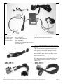
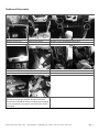
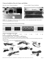
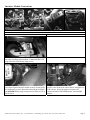
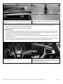
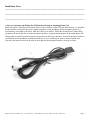
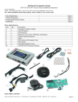
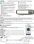
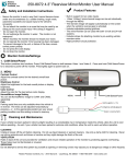
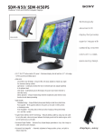
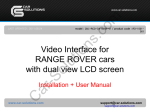
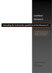
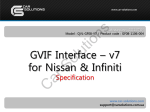
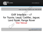
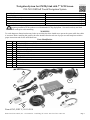
Navigation System for GM MyLink with 7” LCD Screen 250-7610 GM Soft Touch Navigation System Parts Identification Page 1 Assembly Layout Page 2 Dashboard Disassembly Page 3 Interface Module Details Page 4 Interface Module Connections Page 5 Reassembly Page 6 CAUTION: It is strongly recommended to disconnect the negative battery cable for 3 minutes before beginning installation of this product to avoid unintended air bag deployment. Note and record any anti-theft radio codes prior to disconnecting. WARNING To avoid dangerous distractions that may lead to an accident, the driver should never operate the system while the vehicle is in motion. Before installing this product, the seller should inform the end-user of proper use and compliance with the proper instructions and all state and federal laws. Parts Identification Item 1 2 3 4 5 6 7 8 9 10 Qty. 1 1 1 1 1 1 1 1 1 1 Description LCD IN/OUT Harness (GVIF) TP_IN to LCD harness Video-switching control module Stylus TP_IN and LCD_IN Harnesses GPS antenna Navigation Interface Module Vehicle T-harness Membrane switch and harness External speaker 1 8 10 2 5 7 9 3 4 6 Form #5383, REV C, 05-19-2014 Rostra Precision Controls, Inc. - 2519 Dana Dr. - Laurinburg, NC 28352 - 800-732-4744 - rostra.com Page 1 Buick Application Information (All applications listed require a factory-installed 7-inch touch screen) Chevrolet GMC 2012-2014 LaCrosse, 2012-2014 Regal 2012-2014 Verano 2013- 2014Camaro (requires 250-7611 harness) 2013- 2014 Malibu (requires 250-7612 harness) May 2012-2014 Volt with MyLink system 2012-2014 Equinox 2013-2014 Cruze 2012-2014 Terrain with color touch screen - The base model 250-7610 kit includes the TP_IN shown to the left. - The included t-harness is applicable to the 2013-2014 Chevrolet Cruze, 2012-2014 Chevrolet Equinox, May 2012-2014 Chevrolet Volt with GM MyLink system, 2012-2014 GMC Terrain, 2012-2013 Buick LaCrosse, 2012-2014 Buick Regal, and 2012-2013 Buick Verano ONLY. Each vehicle must have a factory-installed, indash 7-inch touch screen. - SOLD SEPARATELY 2013-2014 Chevrolet Malibu and Camaro vehicles require t-harness part numbers 2507611 (Camaro) and 250-7612 (Malibu). See harness images below: Rostra Precision Controls, Inc. - 2519 Dana Dr. - Laurinburg, NC 28352 - 800-732-4744 - rostra.com Page 2 Dashboard Disassembly Step 1 Remove screen visor Step 2 Remove trim panels Step 5 Remove retaining screws from display Step 3 Step 4 Remove screws surrounding storage area Step 6 Remove radio from dashboard Step 7 Disconnect the factory wiring harnesses from the rear of the radio and install the included interface t-harnesses between the radio and the factory wiring harnesses making sure all connections are properly seated and secure before proceeding. Rostra Precision Controls, Inc. - 2519 Dana Dr. - Laurinburg, NC 28352 - 800-732-4744 - rostra.com Page 3 T-harness Installation (Chevrolet Camaro and Malibu) Chevrolet Camaro T-harness Installation Chevrolet Malibu T-harness Installation NOTE: The GVIF harness for both of the vehicles listed above is to be connected to the back of the vehicle’s LCD screen and NOT directly to the radio. Default Programming Switch (Dip Switch) Settings Default Programming Switch Settings 1 – On 2 – Off 3 – On 4 – Off 5 – On Factory or Aftermarket Camera Settings To use an aftermarket camera – Place switch #1 in OFF position. To use the vehicle’s factory camera – Place switch #1 in ON position. 6 – On 7 – Off 8 – On Note: Installer is advised to disconnect the negative battery terminal after any changes are made to the programming switches on the navigation module. Visit www.rostra.com to view all compatible backup cameras! Rostra Precision Controls, Inc. - 2519 Dana Dr. - Laurinburg, NC 28352 - 800-732-4744 - rostra.com Page 4 Interface Module Connections Step 8 Route included t-harnesses behind display housing Step 9 Connect the OEM-IN and LCD-OUT/IN harness plugs to the video switching control module. Connect the blue GVIF plug to the back of the factory touch screen. Step 10 Step 11 Remove the passenger-side panel from the center console and place the navigation interface module securely in front of the air conditioning system’s ductwork connecting the NAV_IN and POWER harness plugs leaving room for future access to the SD Card. Using the adhered double-sided tape, attach the system’s speaker to the inside of the center console facing the rear of the vehicle. Route the speaker’s harness to be connected with the SPEAKER harness from the GPS harness. Rostra Precision Controls, Inc. - 2519 Dana Dr. - Laurinburg, NC 28352 - 800-732-4744 - rostra.com Page 5 Step 12 Route the GPS antenna extension harness from the GPS/Multimedia video interface module to the rear of the vehicle. Step 13 Place the GPS antenna at the top-rear of the vehicle allowing it to attach to the vehicle’s body using its built-in magnet. Reassembly 1. Reinstall all trim pieces taking special care to ensure harnesses and wiring connections are properly secured. 2. Make sure no harnesses are bent or pinched by trim pieces. 3. Reconnect all disconnected bulbs and check for function. Installation Tips Confirm proper cable extension connector orientation and always verify proper ends are routed in correct direction. It is a good idea to dry-fit all pieces in this kit before permanently attaching them to ensure proper orientation and operation before beginning installation for familiarization with components. Always treat any metal exposed during installation with a rust preventative compound to prevent system failure due to rust and/or corrosion. Always seal any holes drilled with the provided sealing putty to prevent water infiltration through unprotected areas. Confirm integrity of mechanical and electrical connections before moving to next installation sequence. Step 14 Once all connections have been made, re-assemble the radio and dashboard. Step 15 If indoors, start the vehicle and move it outside so that the GPS antenna has a clear view of the sky. Press the mute/call decline button to switch from the factory interface to the iGo Navigation interface. Rostra Precision Controls, Inc. - 2519 Dana Dr. - Laurinburg, NC 28352 - 800-732-4744 - rostra.com Page 6 Installation Notes _____________________________________________________________________________ _____________________________________________________________________________ _____________________________________________________________________________ A Note on Activating and Exiting the GPS Interface During an Incoming Phone Call While the vehicle’s steering wheel control allows for the activation of the GPS unit while driving, it is advisable for the installer to also place the surface-mount membrane switch included with this navigation system in a location that is accessible to the driver while the vehicle is in motion. While the steering wheel’s phone hang up button will also let the driver exit the navigation interface, using this button ignores an incoming phone call if being used to transfer from the navigation system back to the factory interface. In such an instance, the driver is advised to use the membrane switch pictured below to do so seamlessly in order to answer a phone call. Likewise, this control switch can be used to enter and exit the navigation interface at any given time. Rostra Precision Controls, Inc. - 2519 Dana Dr. - Laurinburg, NC 28352 - 800-732-4744 - rostra.com Page 7 Rostra Precision Controls, Inc. - 2519 Dana Dr. - Laurinburg, NC 28352 - 800-732-4744 - rostra.com Page 8