1
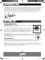
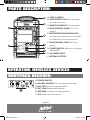
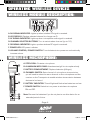
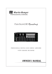
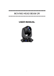
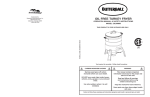
USER MANUAL
TRANSPORTA.indd 1
12/04/10 3:47 PM
TRANSPORTA.indd 2
12/04/10 3:47 PM
CONTENTS:
INTRODUCTION AND SETTING UP 1
SPECIFICATIONS AND PARTS LISTING 2
PARTS DESCRIPTION
3
OPERATING WIRELESS DEVICES
- BODYPACK RECEIVER
- WIRELESS MODULE DESCRIPTION
- WIRELESS MICROPHONE
MAIN CONTROLS
- MAIN CONTROL PANEL 1 DESCRIPTION
- MAIN CONTROL PANEL 2 DESCRIPTION
GENERAL USAGE:
- TURNING ON
- ATTACHING AN MP3 DEVICE
- CHARGING THE UNIT
- WIRELESS MIC PRIORITY
- LINE IN/LINE OUT
- CHANGING THE BATTERY
SAFETY INFORMATION
TRANSPORTA.indd 3
3-4
5
6-7
8
12/04/10 3:47 PM
INTRODUCTION:
Ashton is designed in Australia by a team of industry experts that have years of experience
in the development, design and production of musical instruments and equipment. Ashton’s
range of instruments are a result of years of development and careful testing. Every Ashton
product is designed with value in mind and features the highest quality materials available.
This manual will help you understand some of the great features of your Transporta.
Enjoy,
The Ashton Team
SETTING UP:
INSTALLATION AND CONNECTION
MAINS CONNECTION:
AC CONNECTION: To connect, simply make sure the unit is turned
off and connect to a power source.
To ensure maximum safety, make sure you always check that the AC
type matches your local settings. It is advisable to unplug the unit during
lightning storms or power surges to avoid damage to the electronics of
the device. You may also choose to use a reputable surge protector.
AC INPUT SOCKET
FUSE AND AC
INFORMATION
DC CONNECTION: The unit can also be powered by the DC input socket, this
power connection will only power the unit. It will not charge it. You will need
a DC24V 2.5A adaptor.
DC INPUT
SOCKET
INSTALLATION:
Depending on your live situation, the Transporta can be either placed on the
floor or on a speaker stand. See Ashton’s range of speaker stands (sold separately).
NOTE: The unit is heavy, so if you are putting the unit on a speaker stand, make sure the
stand is on a flat surface and is attached properly. To avoid injury we suggest using two
people to lift the Transporta onto the speaker stand.
- Page 1 -
TRANSPORTA.indd 4
12/04/10 3:47 PM
SPECIFICATIONS:
GENERAL SPECIFICATIONS:
RECEIVER SPECIFICATIONS:
SPEAKER
1 X 10” Woofer & 1 x 1”
Tweeter (at 4ohm)
RF RANGE
UHF 801- 825Mhz
STABILITY
± 0.005%
RECEIVER
MODULE
UHF PLL 16-channel truediversity single receiver
DYNAMIC RANGE
± 40KHz w/level limiting circuit
FREQ. BAND
UHF 600 - 960 MHz
(801 - 825 MHz)
S/N RATIO
>110dB
T.H.D
>105dB
SQUELCH CIRCUIT
Pilotone squelch/PLL synthesised receiver/Non-diversity
FREQ. RESPONSE
50Hz - 18KHz (± 3dB)
RECEIVER MODE
Quartz and tone squelch true
diversity/Single receiver/Nondiversity or PLL system
WIRELESS MIC
CAPSULE TYPE
Dynamic capsule or
condenser capsule
TRANS. RATIO
Approx. 10mW
OUTPUT POWER
120W
CHARGE TIME
6 - 8 Hours
OPERATIVE TIME
3 - 9 Hours
RECHARGABLE
BATTERY
12V/5Ah (2 pieces)
DIMENSIONS
50cm x 32cm x 29cm (HxWxD)
WEIGHT
16kgs
MICROPHONE SPECIFICATIONS:
MIC CAPSULE
Dynamic (EP-900 device ECM)
BODYPACK SPECIFICATIONS:
RF RANGE
600 - 960Mhz
RF RANGE
STABILITY
± 0.005%
STABILITY
± 0.005%
FREQ. RESPONSE
50Hz - 18KHz (± 3dB)
Preset 16 Channels
ANTENNA
Built-in
PRE-PROGRAMMED
FREQUENCY
S/N RATIO
80dB overall
ANTENNA
External
RF OUTPUT
10mW MAX.
WEIGHT
100g
CURRENT
CONSUMPTION
100mA ± 10mA
BATTERY
2 x AA (1.5V)
BATTERY
2 x AA (1.5V)
WEIGHT
230g
UHF 801 - 825Mhz
PARTS LISTING:
1 x Transporta main unit
1 x Hand-held wireless microphone
1 x Bodypack receiver with lapel microphone
1 x AC power cord
4 x AA rechargeable batteries
- Page 2 -
TRANSPORTA.indd 5
12/04/10 3:47 PM
PARTS DESCRIPTION:
A. CARRY HANDLE
B. ACCESSORIES TRAY: Storage space
for mics and cords.
C: WIRELESS MODULE: Turn to page 4.
D. MAIN CONTROL PANEL 1: Turn to
page 5.
E. MICROPHONE RECHARGING BOX:
Simultaneously charge up to 4 wireless
mic batteries in this compartment.
F. M
AIN CONTROL PANEL 2: Turn to
page 5.
G. POWER SWITCH: Switch to turn power
ON and OFF.
H. AC POWER INPUT
I. INTERNAL BATTERY
OPERATING WIRELESS DEVICES
BODYPACK RECEIVER:
A. POWER SWITCH
B. VOLUME CONTROL: Turn to adjust volume level.
C: M
IC INPUT: Input for wireless device.
D. B
AT. LOW: Battery level indicator.
E. A
NTENNA: Antenna is connected here.
F. C
LIP: Clips onto belt or strap.
- Page 3 -
TRANSPORTA.indd 6
12/04/10 3:47 PM
OPERATING WIRELESS DEVICES
WIRELESS MODULE DESCRIPTION:
A. RA SIGNAL INDICATOR: Lights up when wireless RF signal is received.
B. LED DISPLAY: Displays selected channel, to change use D.
C: AF SIGNAL INDICATOR: Lights up when microphone audio signal is received.
D: CHANNEL SELECTOR BUTTONS: Turn to set wireless channel (up to 16).
E. RB SIGNAL INDICATOR: Lights up when wireless RF signal is received.
F. P
OWER LED: LED power indicator.
G. VOLUME CONTROL/POWER SWITCH: Turn clockwise to turn power on and continually
increase volume.
WIRELESS MICROPHONE:
A. STEEL GRILL: Protects microphone.
B. ALUMINIUM NECK RING: Attaches steel grill to microphone body.
C: BATTERY COMPARTMENT: Replace batteries (AA type).
D: CHANNEL SWITCH: Sets channel of microphone transmission,
you will need to select the same channel on the microphone and the
receiver on the Transporta to enable wireless transmission between
devices to be heard.
E. BATTERY INDICATOR: This will light and flash when batteries are low.
F. P
OWER SWITCH: Switch to turn power to wireless microphone
ON and OFF.
Note: Remove the batteries if you do not plan to use this device for an
extended period of time.
- Page 4 -
TRANSPORTA.indd 7
12/04/10 3:47 PM
MAIN CONTROLS
PANEL 1 DESCRIPTION:
A/B. CD/TAPE VOLUME KNOBS: These knobs are only used when
tape deck or CD player is installed.
C: LINE IN VOLUME KNOB & JACK: Volume control for external
audio input. Connect external audio (eg, MP3 or stereo). Level
controlled by C.
D: RCA LINE IN: Plug an RCA device (eg, MP3 or stereo) via this input.
E. E
CHO LEVEL KNOB: Controls the level of echo (delay) on both
the wireless and wired mics.
F. M
IC VOLUME KNOB: Controls the volume level of mics plugged
into either H or I.
G. WIRELESS MIC PRIORITY SWITCH: Switch to engage
microphone priority. See page 6.
H. M
IC INPUT: Connect an external microphone with an 1/4” jack
via this input.
I. MIC INPUT: Connect an external microphone with an XLR jack
via this input.
PANEL 2 DESCRIPTION:
A. EXTENSION SPEAKER
OUTPUT: Output to an
external speaker.
B: DC POWER INPUT:
Provides alternate power to
the unit. (DC24V 2.5A)
C: BATTERY LEVEL INDICATOR: Lights indicate battery power level when not plugged into AC
power. When charging, the lights will flash as the battery charges from low to full. If only one
LED is red, you need to recharge the device.
E. M
AIN VOLUME KNOB: Controls the overall volume of the output.
F. B
ASS CONTROL KNOB: Controls overall bass level in output sound.
G. TREBLE CONTROL KNOB: Controls overall treble level in output sound.
- Page 5 -
TRANSPORTA.indd 8
12/04/10 3:47 PM
GENERAL USAGE
TURNING UNIT ON:
When turning the unit on always make sure all the volume knobs are set to minimum and
unplug any attached devices. This will ensure longer speaker life.
ATTACHING AN MP3 DEVICE:
The best method for connecting an MP3 device to the Transporta is via the RCA inputs
located on the main panel (see panel description on previous page). By using this input you
ensure that both the left and right stereo signals are heard through the device.
Note: Most MP3 players have a 1/8” jack connection, you will need to purchase 2 x RCA to
1/8” adaptor lead (Ashton RCA28S). These can also be found at most music or hi-fi stores.
CHARGING THE UNIT:
When the unit is plugged into your mains power outlet, the unit automatically charges.
When the unit is charging the LED lights located on the main control panel will flash green.
WIRELESS MIC PRIORITY:
When this function is engaged, the wireless microphone output is nominated as the main
sound source and is prioritised in volume level over all other inputted devices. This is a great
function for vocal practice with a backing track or making a speech with background music.
LINE IN:
The “line in” input allows external devices (eg, stereo, instrument, amplifier) to be played through
the Transporta. This input is a 1/4” stereo input.
- Page 6
TRANSPORTA.indd 9
12/04/10 3:47 PM
GENERAL USAGE
CHANGING THE BATTERY:
1. Switch off power to device before changing the batteries.
2. Take out screws on battery plate located on back panel (see diagram).
3. Take batteries out.
4. Match the pole with colour of the battery and it’s subsequent slot and replace batteries.
- Page 7 -
TRANSPORTA.indd 10
12/04/10 3:47 PM
SAFETY INFORMATION:
INSTRUCTIONS RELATING TO RISK OF FIRE, ELECTRIC SHOCK, OR INJURY TO PERSONS.
WARNING!
When using any electronic product, basic precautions should always be followed, including the following:
1. Read all the safety and installation instructions and explanations of graphic symbols and set-up/controls
before using the products.
2.This product must be earthed. In the unlikely malfunction or breakdown, grounding provides a path of
least resistance for electronic current to reduce the risk of electric shock. This product is equipped with
a cord having an equipment-grounding conductor and a grounding plug. The plug must be connected to an
appropriate outlet that is properly installed and earthed in accordance with all local codes and ordinances.
DANGER: Improper connection of the equipment grounding conductor can result in a risk of electric shock.
Check with a qualified electrician or service professional if you are in doubt as to whether the product is
properly grounded. Do not modify the plug provided with the product. If it will not fit the outlet, have a proper
outlet installed by a qualified technician.
3. To reduce the risk of injury, close supervision is necessary when this product is used, especially near children.
4. Do not use this product near water; eg, near a bathtub, sink, in a wet basement, or near a swimming pool.
5. This product, either alone or in combination with an instrument and headphones or speakers, may be capable
of producing sound levels that could cause permanent hearing loss. Do not operate for a long period of time
at a high volume level, or at a level that is uncomfortable.
6. This product should be installed in a location that provides adequate ventilation.
7. This product should be located away from heat sources such as radiators, heat registers, or other products
that produce heat.
8. The product should be connected to a power supply only of the type described in the operating instructions
or as marked on the product.
9. The power-supply cord of the product should be unplugged from the outlet when left unused for a long period
of time. When unplugging the power supply cord, do no pull on the cord but grasp it by the plug.
10. Care should be taken so that objects do not fall and liquids are not spilled into the enclosure through
any openings.
11. The product should only be serviced by qualified service personnel when:
A. The power-supply cord or the plug has been damaged.
B. Objects have fallen on, or liquid has been spilled into the product.
C. The product has been exposed to rain or moisture.
D. The product does not appear to be operating normally, or exhibits a marked change in
performance.
E. The product has been dropped or the cabinet damaged.
12. Do not attempt to service the product beyond that described in the manual instructions. All other servicing
should be referred to qualified service personnel.
13.WARNING ! Do not place objects on products, the power cord or place it in a position where anyone could trip
over, walk on or roll anything over it. Do not allow any part of the product to rest on or be installed over power
cords of any type. Improper installations of this type create the possibility of fire and general safety hazard.
- Page 8 -
TRANSPORTA.indd 11
12/04/10 3:47 PM
[email protected]
TRANSPORTA.indd 12
12/04/10 3:47 PM