1
Version 1.3
DigitalSpot 3000 DT II
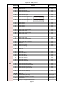
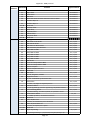
Table of contents
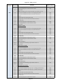
1. Safety instructions ...................................................................................................................................................... 4
2. Unpacking ................................................................................................................................................................... 5
3. Introduction ................................................................................................................................................................ 6
4. Fixture exterior view ................................................................................................................................................... 6
4.1 Placing fixture head covers ................................................................................................................................... 7
5. Video inputs ................................................................................................................................................................ 7
6. Connection to the mains ............................................................................................................................................ 8
6.1 Powering on the DigitalSpot 3000 DT II ................................................................................................................ 8
6.2 Power down mode ............................................................................................................................................... 8
7. Shutting down the DigitalSpot 3000 DT II .................................................................................................................. 8
8. Positioning the DigitalSpot 3000 DT II ........................................................................................................................ 8
8.1 Changing the zoom .............................................................................................................................................10
9. Rigging the fixture.....................................................................................................................................................10
10. DMX 512 connection ..............................................................................................................................................12
11. Ethernet connection ...............................................................................................................................................12
12. Folder organization .................................................................................................................................................14
13. Control menu map ..................................................................................................................................................15
14. Operating modes ....................................................................................................................................................20
15. Control menu ..........................................................................................................................................................20
15.1 Fixture Address .................................................................................................................................................20
15.2 Fixture information ...........................................................................................................................................21
15.3 Personality ........................................................................................................................................................21
15.4 Lamp On/Off .....................................................................................................................................................23
15.5 Manual control .................................................................................................................................................23
15.6 Stand-alone setting...........................................................................................................................................23
15.7 Preview mode. ..................................................................................................................................................25
15.8 Reset functions .................................................................................................................................................25
15.9 Service menu ....................................................................................................................................................25
15.10 Special functions .............................................................................................................................................26
15.11 Fixture Off .......................................................................................................................................................28
16. Keystones ................................................................................................................................................................28
16.1 Global keystone parameters.............................................................................................................................28
16.2 Layer keystone parameters ..............................................................................................................................29
17. In Frame and Out Frame parameters .....................................................................................................................33
18. Video Control ..........................................................................................................................................................33
2
DigitalSpot 3000 DT II
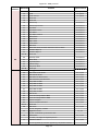
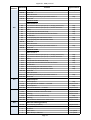
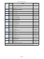
19. Playback speed ......................................................................................................................................................34
20. Graphic effects ........................................................................................................................................................35
20.1 Kaleidoscopic effect ..........................................................................................................................................35
20.2 Circular effect (Fish eye) ...................................................................................................................................37
20.3 RGB (CMY) effects.............................................................................................................................................37
20.4 Iris effect on layer .............................................................................................................................................42
20.5 Auto iris effect on layer ....................................................................................................................................45
20.6 Zoom effects on layer .......................................................................................................................................45
20.7 Another graphic effects on layers.....................................................................................................................46
21. Media content management ..................................................................................................................................48
21.1 Moving files between the fixture and a PC ......................................................................................................48
21.2 Moving files between networked fixtures........................................................................................................52
22. Remote control of the fixture via WWW browser .................................................................................................52
23. Picture merging.......................................................................................................................................................56
23.1 Picture merging control channels .....................................................................................................................56
23.2 Picture merging example ..................................................................................................................................64
24. Pre-cut content mode for Picture Merging ........................................................................................................... 65
25. Effect video synchronization ..................................................................................................................................67
26. Projection onto angular, cylindric or spheric surfaces ...........................................................................................68
26.1 Curved surface support channels .....................................................................................................................68
26.2 Rectangle onto circle (sphere) mapping with picture merging ........................................................................70
27. Video processing on gobo layers from a streaming video server ..........................................................................71
28. RDM ........................................................................................................................................................................78
28.1 CITP/MSEX protocol .........................................................................................................................................78
29. Technical specifications ..........................................................................................................................................80
30. Error and information messages ............................................................................................................................83
31. Maintenance ...........................................................................................................................................................85
31.1 Replacing the lamp ...........................................................................................................................................85
31.2 Replacing the projector ....................................................................................................................................87
31.3 Replacing the air filters .....................................................................................................................................88
31.4 Replacing the fuse ............................................................................................................................................89
31.5 System restore ..................................................................................................................................................89
31.6 Installing the DVI/VGA capture card.................................................................................................................90
31.7 Installing the SDI/ASI capture card ...................................................................................................................91
31.8 Cleaning ............................................................................................................................................................92
3
DigitalSpot 3000 DT II
FOR YOUR OWN SAFETY, PLEASE READ THIS USER MANUAL CAREFULLY
BEFORE POWERING OR INSTALLING YOUR DIGITALSPOT 3000 DT II !
Save it for future reference.
This device has left our premises in absolutely perfect condition. In order to maintain this condition and to ensure a
safe operation, it is absolutely necessary for the user to follow the safety instructions and warning notes written in
this manual.
The manufacturer will not accept liability for any resulting damages caused by the non-observance of this manual
or any unauthorized modification to the device.
Please consider that damages caused by manual modifications to the device are not subject to warranty.
The DigitalSpot 3000 DT II was designed for indoor use and it is intended for professional application only.It is
not for household use.
1. Safety instructions
DANGEROUS VOLTAGE CONSTITUTING A RISK OF ELECTRIC SHOCK IS PRESENT WITHIN THIS UNIT!
Make sure that the available voltage is not higher than stated on the rear panel of the fixture.
This fixture should be operated only from the type of power source indicated on the marking label. If you are not
sure of the type of power supplied, consult your authorized distributor or local power company.
Always disconnect the fixture from AC power before cleaning, removing or installing the fuses, or any part.
Make sure that the power switch is set to off-position before you connect the fixture to the mains. The power plug
has to be accessible after installing the fixture. Do not overload wall outlets and extension cords as this can
result in fire or electric shock.
Do not allow anything to rest on the power cord. Do not locate this fixture where the cord may be damaged by
persons walking on it.
Make sure that the power cord is never crimped or damaged by sharp edges. Check the fixture and the power cord
from time to time.
Refer servicing to qualified service personnel.
This fixture falls under protection class I. Therefore this fixture has to be connected to a mains socket outlet with a
protective earthing connection.
Do not look straight at the fixture objective lens or LED module during operation. The intense light beam may
damage your eyes.
If the device has been exposed to drastic temperature fluctuation (e.g. after transportation), do not switch it on
immediately. The arising condensation water might damage your device. Leave the device switched off until it has
reached room temperature.
Do not shake the device. Avoid brute force when installing or operating the device.
This fixture was designed for indoor use only, Do not expose this unit to rain or use near water.
4
DigitalSpot 3000 DT II
When choosing the installation spot, please make sure that the device is not exposed to extreme heat, moisture or
dust.
Air vents and slots in the fixture´s head and base are provided for ventilation, to ensure reliable operation of the
device and to protect it from overheating.
The openings should never be covered with cloth or other materials, and never must be blocked.
This fixture should not be placed in a built-in installation unless proper ventilation is provided.
Always use a secondary safety cable when mounting this fixture.
Only operate the fixture after having checked that the housing is firmly closed and all screws are tightly fastened.
Make sure that the area below the installation place is blocked when rigging, derigging or servicing the fixture.
Do not block the front objective lens with any object when the fixture is under operation.
The lamp becomes extremely hot during operation. Allow the fixture to cool approximately 40 minutes prior to
removing the lamp assembly for replacement. Do not operate lamps beyond the rated lamp life.
Operate the fixture only after having familiarized with its functions. Do not permit operation by persons not
qualified for operating the fixture. Most damages are the result of unprofessional operation!
Please use the original packaging if the fixture is to be transported.
Please consider that unauthorized modifications on the fixture are forbidden due to safety reasons!
If this device will be operated in any way different to the one described in this manual, the product may suffer
damages and the guarantee becomes void. Furthermore, any other operation may lead to dangers like shortcircuit, burns, electric shock, lamp explosion, crash etc.
To switch the DigitalSpot 3000 DT II off, always use either option "Fixture Off" in main menu or set a DMX value of
channel 8 between 240-249.
Never switch the fixture off by pulling out the power plug from the socket otherwise the fixture may be damaged
(projector lamp, operating system...)!
2. Unpacking
The DigitalSpot 3000 DT II is packaged in either a cardboard box or one-unit (two-unit) flight case to protect the
product during shipment.
The following items are included:
- the DigitalSpot 3000 DT II
- 2 omega holders
- the USB 2.0 flash drive with a System recovery utility
- this user manual
5
DigitalSpot 3000 DT II
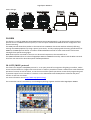
3. Introduction
The DigitalSpot 3000 DT II features moving head with a video projection and automated lighting technologies
including a DMX controllable digital media server installed in a fixture´s base. The built-in 32-bit Graphics Engine
utilizes Linux and DirectX application programming interface to provide extensive image control of graphic objects.
The Digital spot 3000 DT II uses DMX512 protocol to control hardware functions like pan, tilt, and focus, as well as
media fixture capabilities including loading images and movies. The graphics engine allows you manipulate
position, scale, rotation, apply visual effects and colour mix each image.
S-Video and VGA inputs for direct input to data projectors are handy for performing presentations.
S-Video and Composite live inputs can be used in graphics effects of DigitalSpot 3000 DT II
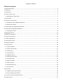
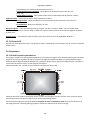
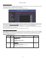
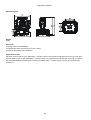
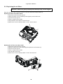
4. Fixture exterior view
1 - Top head cover
2 - Projector aperture
3 - LED Wash module
4 - Yoke
5 - Pan lock/unlock latch
6 - Control board
7 - Base
8 - Handle
9 - Bottom head cover
10 - Tilt unlock button
(green)
11 - Tilt lock button (red)
Front panel of fixture base
1 - Display
2 - Rotary control wheel
3 - Escape button
4 - Enter button
6
DigitalSpot 3000 DT II
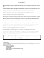
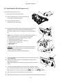
Rear panel of the fixture base
1 - AT power
2 - Power cord
3 - Power switch
4 - Fuse
5 - Composite input-graphic engine
6 - S-video input- graphics engine
7 - DMX input/output (5-pin XLR)
8 - LAN (RJ-45) port
9 - DMX input/output (3-pin XLR)
10 - 2 x USB port
11 - S-video input-dataprojector
12 - Composite input-dataprojector
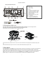
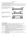
4.1 Placing fixture head covers
The head cooling fans are fixed in head covers and their supply is realized by a pair of springy contacts.
The head covers cannot be interchanged otherwise the fans will not work.
Pay attention to correct placing the covers on the fixture head.
The top head cover (1) does not has air vents at its front and shelters the top projector side with the lamp cover
(3).
The bottom head cover (2) has air vents at its front and shelters bottom projector side.
5. Video inputs
Both Composite (8) and S-Video (9) inputs provide direct connection to the projector. The inputs are intended for a
static presentation as data going through the inputs cannot be processed in a graphics engine ,it means that
graphics effects from a DMX protocol will not be usable. In this use of the fixture, the function of Keystoning from a
DMX protocol will not operate. Next both inputs Composite (10) and S-Video (11) enable to process data in a
graphics engine, it is means that you can use all spectrum of effects that the DMX protocol offers
7
DigitalSpot 3000 DT II
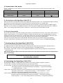
6. Connection to the mains
Install a suitable plug on the power cord, note that the cores in the power cord are colored according to the
following table.
Core (Eu)
Core (US)
Pin
Symbol
Brown
Black
Live
L
Light blue
White
Neutral
N
Yellow/Green
Green
Earth
The earth has to be connected!
6.1 Powering on the DigitalSpot 3000 DT II
When the fixture is connected to the AC mains supply and the power switch is on, it automatically begins a homing
procedure to verify that all functions of the fixture and its internal projector are in good order.
Note: If the fixture was switched off by DMX command (channel 8 “Power / Special Functions” DMX range of
240-249), you can switch it on by DMX command on the same channel: DMX range of 45-49, function “Wake On
DMX “ or by sending a special data packet via Ethernet – fixture supports function Wake On LAN.
6.2 Power down mode
This mode omits fixture reset after switching the fixture on and deactivates all motors. The "Power down mode" is
useful in special events e. g. if the fixture is placed in a flight case and you want to set its DMX address without
taking it out from the case.To enter the "Power down mode",press and hold the [ENTER] button and at the same
time switch on the Power switch. Press the [ESC] button to see a notice "Power Down Mode."
Now you can use the fixture menu to set desired behaviour of the unit. If you want to go to the standard
operation mode without switching the fixture off, run total reset of the fixture (menu item Reset all Systems ).
7. Shutting down the DigitalSpot 3000 DT II
There are two recommended ways how to shutdown the fixture:
1. A DMX controller can switch off the projector lamp and shut down the fixture with the "Lamp Off, Fixture
Off" option on the control channel 8 “Power / Special Functions” (see DMX protocol).
2. The option "Fixture Off" in main menu of DigitalSpot 3000 DT II switches off the projector´s lamp and shuts
down the fixture.
After shutting down the fixture switch the power switch on the rear side of the fixture base to the off position in
order to save energy.
Removing power directly without the shutdown procedure
can reduce fixture reliability!
8. Positioning the DigitalSpot 3000 DT II
The DigitalSpot 3000 DT II is designed to be installed in one of four possible installation locations:
1. Front Table - the fixture is placed near the floor in front of the screen.
2. Front Ceiling - the fixture is suspended upside-down from the ceiling (truss) in front of the screen.
Set Ceiling Projection in the menu Personality ("Personality--->"Projection Presetting"
--->"Ceiling Projection"--->"On")
3. Rear Table - the fixture is placed near the floor behind the screen. Set Rear Projection in the menu
Personality ("Personality--->"Projection Presetting"--->"Rear Projection"--->"On")
Note that a special rear projection screen is required.
4. Rear Ceiling - the fixture is suspended upside-down from the ceiling (truss) behind the screen.
Set Rear Projection in the menu Personality ("Personality--->"Projection Presetting"--->
"Rear Projection"--->"On") and Ceiling Projection ("Personality--->"Projection Presetting"
8
DigitalSpot 3000 DT II
--->"Ceiling Projection"--->"On")
Note that a special rear projection screen is required.
When determining the position of the fixture and projection screen, you will need to account for the projected
image size, which is directly proportional to the projection distance.
There is a chart of throw distance ratio of 1.93-2.16 : 1 to assist you in determining the ideal location for your
fixture.
Min zoom is default setting. Max. zoom is possible after manual adjustment only. See instructions below.
Note: There is a tolerance among these numbers due to optical component variations. We recommend that if you
intend to permanently install the DigitalSpot 3000 DT II, you should physically test the projection size and distance
using the actual fixture in m before you permanently install it, so as to make allowance for this projector's optical
9
DigitalSpot 3000 DT II
characteristics. This will help you determine the exact mounting position so that it best suits your installation
location
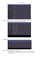
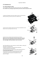
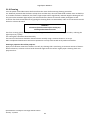
8.1 Changing the zoom
1. Turn the power off and if the projector lamp was on, wait 10 minutes until the projector has cooled.
2. Remove the top cover of the fixture head by loosening the four quarter-turn fasteners (1).
3. Unscrew 2 fastening screws (2) which securing the focus driving motor (3). Turn the motor up in order to allow
an access to the zoom ring (4).
4. Turn the zoom ring to the left position to set max. zoom. (Right position-min. zoom-default setting).
5. Tilt the focus driving motor back to the chassis and secure it by 2 crews.
6. Fasten the top cover back on the fixture head.
9. Rigging the fixture
Please consider the respective national norms during the installation!
Verify the truss or support will handle the combined weight of all the fixtures on the truss
Always use a secondary safety cable when mounting this fixture
When rigging, derigging or servicing the fixture staying in the area below the installation place, on bridges, under
high working places and other endangered areas is forbidden.
The operator has to make sure that safety-relating and machine-technical installations are approved by an expert
before taking into operation for the first time and after changes before taking into operation another time.
The operator has to make sure that safety-relating and machine-technical installations are approved by a skilled
person once a year.
To ensure reliable operation of the product and to protect it from overheating, the vents must not be blocked or
covered.
Hot air is exhausted from the exhaust vent. Do not put any flammable object near the fixture, hot air is exhausted
from the air vents.
Keep the exhaust vents at least 1 m away from any objects.
Do not touch peripheral parts of the exhaust vent, especially screws, grids and metallic parts. These areas
will become hot while the fixture is being used.
Do not put anything on the fixture. Objects put on the fixture will not only get damaged but also may cause fire
hazard by heat.
Allow the fixture to cool for 20 minutes before handling.
The fixture should be installed out of the reach of people.
IMPORTANT! Overhead rigging requires extensive experience, including calculation of working load limits,
installation material being used, and periodic safety inspection of all installation material and the fixture. If you lack
10
DigitalSpot 3000 DT II
these qualifications, do not attempt the installation yourself, but instead use a professional structural rigger.
Improper installation can result in bodily injury and or damage to property.
The fixture must never be fixed swinging freely in the room.
Use 2 appropriate clamps to rig the fixture on a truss.
Make sure that the device is fixed properly!
Ensure that the structure (truss) to which you are attaching
the fixtures is secure.
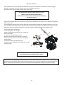
A pair of the Omega holders can be placed in 2 positions on the bottom of the base. Use 2 clamps (not supplied)
with screws M12.
For overhead use, always install a safety cable that can hold at least 10 times the weight of the fixture. You must
only use safety cables with screw-on carbines. Pull the safety cable through the two apertures on the bottom of
the base and over the trussing system etc. Insert the end in the carbine and tighten the fixation screw.
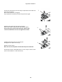
To install the fixture on the truss:
1. Bolt clamp (1) to the omega
holder (2) with M12 bolt and lock nut through the
hole in the holder.
2. Fasten the omega holders on the
bottom of the base by inserting both quick-lock
fasteners (3) into the holes of the base and tighten
fully clockwise.
3. Fasten the safety-rope (4) through the
two apertures in the bottom of the base and over the
trussing system.
Before taking into operation for the first time,
the installation has to be approved by an expert!
We recommend avoiding dusty/smoky environments when operating the fixture. Usage in these environments may
cause a poor image quality. When using the projector under dusty or smoky conditions,dust may accumulate on a
lensor optical elements inside the projector. Such condition may degrade the quality of the projected image.
11
DigitalSpot 3000 DT II
10. DMX 512 connection
The fixture is equipped with both 3-pin and 5-pin XLR sockets for DMX input and output. Only use a shielded twistedpair cable designed for RS-485 and 3-pin/5-pin XLR- connectors in order to connect the controller with the fixture
or one fixture with another.
Wiring of the XLR connectors:
DMX output
XLR mounting sockets (rear view):
1 – Shield
2 - Signal (-)
3 - Signal (+)
DMX input
XLR mounting plugs (rear view):
4 – Not connected
5 – Not connected
To build a DMX chain
1. Connect the DMX output of the first fixture in the DMX chain with the DMX input of the next fixture. Always
connect one output with the input of the next fixture until all fixtures are connected.
2. Use menu "DMX Settings " to set the DMX start address on all fixtures (see the "Fixture address" menu).
3. The option Activate DMX mode has to be confirmed in the “DMX Settings" menu on all fixtures.
Do not overload the link. Max. 32 fixtures may be connected on a DMX link.
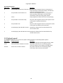
Example:
Caution: Terminate the link by installing a termination plug in the DMX output of the last fixture. The termination
plug is a male 3-pin XLR plug with a 120 Ohm resistor soldered between Signal (–) and Signal (+).
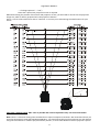
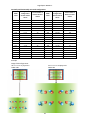
11. Ethernet connection
The fixtures on a data link are connected to the Ethernet network with an Art-Net communication protocol. The
controlling software from PC (or lighting console) has to support the Art-Net protocol.
The Art-Net communication protocol is a 10 Base T Ethernet protocol based on the TCP/IP. Its purpose is to allow
transfer of large amounts of DMX 512 data over a wide area using standard network technology.
IP address is the Internet protocol address. The IP uniquely identifies any node (fixture) on a network.
The Universe is a single DMX 512 frame of 512 channels.
The the DigitalSpot 3000 DT II is equipped with 8-pin RJ- 45 socket for Ethernet input. Use a network cable category
5 (with four “twisted” wire pairs) and standard RJ-45 plugs in order to connect the fixture to the network.
RJ-45 socket (front view):
1- TD+
RJ-45 plug (front view):
5- Not connected
12
DigitalSpot 3000 DT II
2- TD3- RX+
4- Not connected
6- RX7- Not connected
8- Not connected
Patch cables that connect fixtures to the hubs or LAN sockets are wired 1:1, that is, pins with the same numbers
are connected together:
1-1
2-2
3-3
4-4
5-5
6-6
7-7
8-8
If only the fixture and the computer are to be interconnected, no hubs or other active components are needed. A
cross-cable has to be used:
1-3
2-6
3-1
4-8
5-7
6-2
7-5
8-4
Ethernet operation.
Connect the Ethernet inputs of all fixtures in the fixture chain with the network.
Use the menu "Artnet Settings " to set an IP address , artnet universe and artnet subnet on all fixtures (see the
"Fixture address" menu).
The option “Activate Artnet mode" has to be confirmed in “Artnet Settings ” menu on all fixtures.
Example:
(DMX address=1)
DMX address=273
IP address=002.168.002.004
Artnet Universe=1
Artnet Subnet=0
DMX address=137
IP address=002.168.002.003
Artnet Universe=1
Artnet Subnet=0
13
DMX address=1
IP address=002.168.002.002
Artnet Universe=1
Artnet Subnet=0
DigitalSpot 3000 DT II
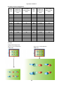
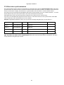
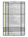
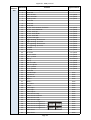
12. Folder organization
The library structure is reflected on the hard drive where all files for the library are stored. The whole library is
contained within a special folder called ‘Media’.
Inside the Media folder is a collection of folders (000,001...240) each named with a 3-digit number. Each folder
following this convention represents a library folder and the 3-digit number represents the name of the folder.
Because of this, you can’t have folders without the 3 digit number scheme. You can’t neither have two folders with
the same digits.
Inside each folder is a collection of media files that the library folder holds. The media files also should follow the
3-digit conventions where a 3-digit number is followed by an underscore and a name e.g.: 001_testfile1.png.
Note that for media files the digit starts at 001_ since visual 0 is always considered as being empty.
The media files assigned to the DMX values can be sorted either in an alphabetical or numerical order. Default
assigning is the alphabetical order. If you need to change this sorting, go to the menu ”Personality“ and select
“Gobo selection mode“ option.
The numerical order is suitable in the case that you need to exactly assign certain media files to specified DMX
addresses.
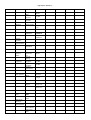
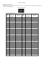
The table below show differences in fileDMX assignment between the alphabetical and numerical sorting.
The table also includes file names without a correct 3-digit convention to illustrate their behaviour in
the numerical sorting.
Media file name
DMX value
DMX value
at Alphabetical Sorting
at Numerical Sorting
001_testfile1.png
1
1
020_testfile2.png
2
20
19_testfile3.png
3
19
3_testfile4.png
4
3
460_testfile5.png
5
Not Assigned*
testfile6.png
6
Not Assigned**
* The 3-digit number has to be in range of 001-255. If there is more than 255 media files in the folder, files above
255 are ignored.
** The media file name does not contain any digit.
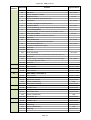
Subfolders 000-020 are reserved for default gobos and videos (from factory) and their content cannot be
changed.
The images and video clips can be in one of the following formats: bmp, jpg, tga; .png, gif, pcx, pnm, xpm and lbm
for images and mpeg1, mpeg2 for videos.
The folder "Programs" serves for saving recorded DMX programs (dprg_01.csv,......dprg_10.csv).
The folder named "Update" contains subfolders with the update files.The subfolders are created automatically
during software updating and their names matching to date when software update has been executed.
The folder a "Log" serves for saving log files generate by the option "Generate Log File" in a menu "Special
Functions" of the control panel.Log file names are deducated from the date when the file has been logged out.
Top level folder
Media
000
001
002
:
240
Programs
Update
13-08-06_09:15:33
:
01-03-06_14:23:50
Log
14
DigitalSpot 3000 DT II
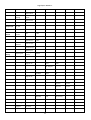
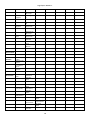
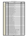
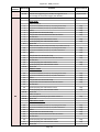
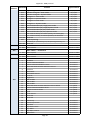
13. Control menu map
Default settings=Bold print
Menu Level 1
Menu Level 2
Fixture
Address
DMX Settings
Ethernet
Settings
Menu Level 3
Set DMX
Address
Activate DMX
Mode
Set IP Address
Set ArtNet
Universe
Set ArtNet
Subnet
Activate
Artnet Mode
Fixture
Information
DMX Values
Pan
Menu Level 4
Menu Level 5
001-512
Default IP
Address
Custom IP
Address
Gateway
Address
0-15
0-15
0-255
:
Synchro to L3
Media Disk
Space Usage
Software
Version
GPU Info:
0-255
Free Disk
Space
Used Disk
Space
Graphic
Engine
IC1
Motherboard
IC2
Motherboard
IC3
Motherboard
IC1
HeadBoard
GPU
Video Bios
Driver Version
Display Device
Product IDs
Mac Addr.
RDM UID
Personality
Pan Reverse
On, Off
Tilt Reverse
On, Off
Lamp
Presetting
Lamp
On/Power On
On, Off
15
Menu Level 6
Menu Level 7
Menu Level 8
DigitalSpot 3000 DT II
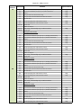
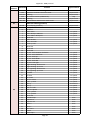
Menu Level 1
Menu Level 2
Display
Adjusting
Menu Level 3
Menu Level 4
Lamp Off via
DMX
On, Off
Lamp On If DMX
is Present
On, Off
Lamp Off if
not DMX
Display
Permanent On
Menu Level 5
On, Off
Display Off After
5 min
Permanent On
Display
Orientation
Pan/Tilt
Feedback
Normal
Orientation
Rotated
Orientation
On, Off
Pan/Tilt Mode
Time Mode
Speed Mode
Active
Blackout
While:
Projection
Presetting
During
Movement
Cor.
Pan/Tilt
Moving
Ceiling
Projection
Rear
Projection
Projector
Refresh Rate
On, Off
On, Off
On, Off
On, Off
60Hz (Default)
50Hz
Dmx Protocol
Set DMX
Mode
No Server
2 Layers
3 Layers
Protocol
Version
Version 1.0
Version 1.2
Gobo Selection
Mode
Alphabetical
Order
Numerical
Order
Microphone
Sensitivity
1..10..20
Verbose Mode
Verbose Mode 0
Verbose Mode 1
DMX Verbose
Mode
16
Menu Level 6
Menu Level 7
Menu Level 8
DigitalSpot 3000 DT II
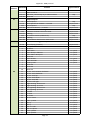
Menu Level 1
Menu Level 2
Menu Level 3
Menu Level 4
Menu Level 5
Menu Level 6
Pan
0-255
:
Tilt
0-255
Program 10
Focus
0-255
Menu Level 7
Synchro
Verbose Mode
Default
Settings
Set Default
Values
Remove User
Media Content
Lamp On/Off
On, Off
Manual
Control
Manual DMX
Control
Pan
0-255
:
Synchro to L3
Video Input
Selection
0-255
Internal Input
External
Composite Input
Stand-alone
Setting
Play Program
External
SVideo Input
Test program
In Loop
Program 1
Normal
Static
Run Program
Edit Program
Program 1
:
Edit Steps
Program 10
Step 1
Pan
:
:
Step 99
Synchronization To
ID
Step Time
0.1-25.5
Fade Time
0.1-25.5
Snap DMX
Save
Music Trigger
On, Off
Play DMX
Program
DMX Program
1 in Loop
Start Step
1-99
End Step
1-99
:
17
Save and Copy
Menu Level 8
DigitalSpot 3000 DT II
Menu Level 1
Menu Level 2
Menu Level 3
Record DMX
Program
DMX Program
10 in Loop
DMX Program
1
Menu Level 4
Menu Level 5
:
DMX Program
10
Preset
Playback
Deactivated
:
Fixture Off
Timer
DMX Program
10 in Loop
Timer
Deactivated
Timer
Activated
Set Timer
Hours
Set Timer
Minutes
Preview Mode
Reset
Functions
Reset Graphics
Engine
Reset Pan/Tilt
System
Reset
Focus/Shutter
System
Reset All
Systems
Service Menu
Power On
Time
Total Hours
Resetable
Hours
Lamp On Time
Total Hours
Resetable
Hours
Lamp Strikes
Total Strikes
Resetable
Strikes
Fixture
Temperatures
Current
Pan/Tilt Board
LED Panel
Board
Maximum
Nonresetable
Pan/Tilt Board
LED Panel
Board
Maximum
Resetable
Pan/Tilt Board
18
Menu Level 6
Menu Level 7
Menu Level 8
DigitalSpot 3000 DT II
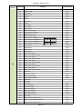
Menu Level 1
Menu Level 2
Menu Level 3
Menu Level 4
Menu Level 5
Menu Level 6
Menu Level 7
Menu Level 8
Media
Open
000
Open
LED Panel
Board
Air Filters
Special
Functions
Time To Clean
Up Filters
Set clean Up
Timer
Regenerate
Thumbnails
Set Thumbnail
size
Regenerate
Thumbnails
FTP Server
Set Account
Allow
Anonymous
HTTP Access
USB Data
Synchronize
10..50..300
50..96...300
Yes/No
Set Account
Allow
Anonymous
Yes/No
USB1
Open
USB2
:
240
Synchronize to
Fixture
Synchronize
from Fixture
Update
Open
Synchronize to
Fixture
Synchronize
from Fixture
Init Flash Disc
Software
Update
Calibrate Values
Update
Graphical
Software
Update HW
processors
Software
Update Media
Content
Analog Shutter
Calib.
0-255
Tilt Calibration
0-255
Set Service IP
Address
Remote IP
Address
077.084.000.224
Remote Port
08283
Service Port
08290
Gateway
Address
002.001.001.001
Generate Log
File
Remote Servis
Set Default
Gateway
Start Remote
Service
19
Synchronize to
Fixture
Synchronize
from Fixture
DigitalSpot 3000 DT II
Menu Level 1
Menu Level 2
Menu Level 3
Menu Level 4
Menu Level 5
Menu Level 6
Menu Level 7
Menu Level 8
Fixture Off
14. Operating modes
Before operating the DigitalSpot 3000 DT II from a DMX 512 controller, you need to define the source of DMX data,
which may be:
DMX 512 - data is transmitted over standard DMX cables. Set a valid DMX start address, which is defined as the
first channel from which the DigitalSpot 3000 DT II will respond to the controller.
Please, be sure that you don’t have any overlapping channels in order to control each DigitalSpot 3000 DT II
correctly and independently from any other fixture on the DMX data link.
For DMX start address setting, please refer to the instructions under "Fixture Address".
ArtNet - data is transmitted over Ethernet network using Artnet protocol. Set an IP address, Artnet Universe and
Artnet Subnet.
For Artnet setting, please refer to the instructions under "Fixture Address".
15. Control menu
The control panel situated on the front panel of the base offers several features. You can simply set the fixture
addresses, configure the fixture, run test, make a reset and also use many functions for setting fixture
behaviour.
Control elements on the control board:
[RNS] encoder wheel-moves between menu items on the same level, scrolls between values.
[ESC] button-leaves menu without saving changes
[ENTER] button-enters menu, confirms adjusted values and leaves menu
After switching the fixture on,
than press [ENTER] and
the display shows the initial screen:
the display shows address:
The main menu of the control panel is accessed by pressing the [ENTER] button. To browse through the menu,
rotate the [RNS] wheel. To select a function or submenu, press the [ENTER] button.
15.1 Fixture Address
Use this menu to set the DMX address.
DMX Setting --- Select this submenu to set the DMX start address.
Set DMX Address - sets DMX address. After selecting desired DMX address confirm setting
by using the function "Activate DMX Mode":
Activate DMX Mode - Data is received from DMX input.
Artnet Setting --- Select this submenu to set the fixture for Ethernet operating.
Set IP Address - Select this submenu to set an IP address and NetMask.
The IP address is the Internet protocol address and uniquely identifies any node (fixture) on
a network. There can't be 2 fixtures with the same IP address on the network!
20
DigitalSpot 3000 DT II
Default IP Address -Preset IP address.
Custom IP Address - The option enables edit all numbers of the IP address.
To set the custom IP address:
1. Select „Custom IP Address” and press the [ENTER].
2. Use RNS wheel to set the first number of the IP address
3. Press the [ENTER] to move on the second number of the IP address
4. Repeat steps 2 and 3 for the third and fourth number of the IP address.
If you want to return back on the previously edited number, press [ESC].
The same way you can set the Netmask Address.
Gateway Address –Option allows to set gateway address.
Set ArtNet Universe - Select this submenu to set a Universe (0-15). The Universe is
a single DMX 512 frame of 512 channels.
Set ArtNet Subnet - Select the option to set Ethernet subnetworks to which the fixture
belongs (0-15)
After setting all Artnet parameters confirm setting by using the function
"Activate Artnet Mode":
Activate Artnet Mode - Data is received from the Ethernet input.
15.2 Fixture information
DMX Values --- Select this item to read DMX values of each channel received by the fixture.
Media Disk Space Usage --- Select the item to read information about the hard disk space.
Free Disk Space --- Select the item to show a size of free hard disk space (MB).
Used Disk Space --- Select the item to show a size of used hard disk space (MB).
Software Version --- Select this function to read the software version of the fixture modules:
Graphic Engine - a graphic software of the fixture.
IC1 Motherboard - a processor IC1 on the main board in the fixture base (the IC1 controls
communication, DMX, fans, temperatures).
IC2 Motherboard - a virtual EEPROM.
IC3 Motherboard - a processor IC3 on the main board in the fixture base (the IC3 controls
pan, tilt, LEDs).
IC1 Headboard - a processor IC1 in the fixture head (the IC1 controls focus and shutter).
GPU Info --- Select the item to read information about graphics processing unit, drivers and type of the projector.
Product IDs --- Select the function to read the MAC address and the RDM UID code.
15.3 Personality
Use this menu to modify DigitalSpot 3000 DT II operating behaviour.
Pan Reverse --- Select this function to invert the pan movement.
Tilt Reverse --- Select this function to invert the tilt movement.
Lamp Presetting --- Select this menu to change the lamp “behaviour”.
Lamp On/Power On - Select this function to turn the projector´s lamp on automatically
after switching the fixture on.
Lamp Off via DMX - Select this function to switch the lamp off via DMX.
Lamp On if DMX Present - This function allows you to strike the lamp automatically after
26 seconds if a DMX signal is present on the data link.
21
DigitalSpot 3000 DT II
Lamp Off if not DMX - This function allows you to switch off the lamp automatically after 2
minutes if a DMX signal is missing on the data link.
Display Adjusting --- This function allows you to change the display settings:
Display Permanent On - This function allows you to keep the display permanent on or
to turn it off after 5 minutes of inactivity of control buttons (wheel)
Display Orientation - Select this function to adjust the display orientation:
Normal orientation - A standard display orientation.
Rotated Orientation - Inverts the display by 180°.
Pan/Tilt Feedback --- This function allows to return the moving head to the required pan/tilt position after
changing the position by an external force (e.g. by a stroke).
Be careful, the Pan/Tilt Feedback OFF is not the standard operation and the head of the fixture can be damaged!
Note: If the feedback was switched off ,the pan/tilt position is changed by an external force and the feedback is
switched on again, the moving head might not to be synchronized with the DMX signal. You have to make a reset in
order to synchronize the moving head with the DMX signal.
Pan/Tilt mode --- Use this menu to set the character of the pan/tilt movement.
Time mode --- Pan and tilt will move with different speeds and they will come at the same
time to the end point (pan and tilt sets its optimal speed).
Speed Mode --- Pan and tilt will move with the same speed as adjusted by the channel 5
(Pan/Tilt speed). E.g. pan will come to the end point and wait for tilt, which has
longer track.
Active Blackout while: --- Use this function if you wish to close the light output during the following events:
During Movement correction --- Select this function to enable the blackout during the head
movement correction (if the moving head lost its right pan/tilt position for a short moment).
Pan/Tilt Moving --- This function closes the light output during pan/tilt changing.
Projection Presetting --- Use this menu depending on the installation location of the fixture:
Ceiling Projection --- When this function is "On", a picture is top (bottom and left) right
reversed.This function enables to project the image from a ceiling mounting of
the DigitalSpot 3000 DT II.
Rear projection --- When this function is "On", picture is left (right) reversed.
This function enables to project the image to a rear projection screen.
Projector Refresh Rate --- Use this menu to change the output refresh rate of the DigitalSpot´s
projector from 60Hz to 50 Hz.
The function should be used in cases when output of DigitalSpot 3500DT is captured by the video
cameras with a fixed 50Hz refresh rate and they are not allowed to adjust embedded 60Hz picture
refresh rate of the DigitalSpot,in these cases some flickering would be visible in an image.
Note. All fixures used in a show must have the same projector refresh rate setting.
DMX protocol --- Use this menu to set desired number of gobo/video layers and DMX channels.
Set DMX mode --- the item allow you to select a desired number of control channels
No Server --- the fixture uses first 17 control channels of DMX chart (1-17).
2 Layers --- 108 control channels (1-108).
3 Layers --- 136 control channels (1-136).
Protocol Version --- the item allow you to select a desired protocol version.
Gobo Selection Mode --- Use this menu to select desired sorting of media files in media subfolders.
Alphabetical Order --- The media files are assigned to DMX values in an alphabetical order.
Numerical projection --- The media files are assigned to DMX values in a numerical order.
Microphone Sensitivity --- Select this item to adjust the microphone sensitivity from 1 (maximum)
to 20 (minimum).
22
DigitalSpot 3000 DT II
Verbose Mode --- Use this menu to hide messages displayed on the screen when you are changing some setting
on the Power/Special functions channel (e.g. Rear projection on, Rear projection off.....) .
Verbose Mode 0 --- Generated messages are hidden.
Verbose Mode I --- Generated messages are visible on the projection screen.
DMX Verbose Mode --- It displayes information regards picture at the bottom left corner of
the image (channel, name, DMX value):
Synchro Verbose Mode --- used for debugging of video synchronization.
Default Settings --- Select this option to set default values or to remove user´s content in the fixture.
Set Default Values --- Select this option to reset all fixture personalities to the default values.
Remove User Media Content --- The item deletes all user media contents except the factory media
content.
15.4 Lamp On/Off
Use this option in order to switch on/off the projector´s lamp.Do not use the projector continuously for 24 hours or
more. If using the projector continuously for long periods, turn it off and leave it for one hour at least once during a
24 hour period.
15.5 Manual control
Manual DMX control ---Select this menu to control all channels by the control elements on the control board.
Video Input Selection ---This menu enables to select desired video input:
Internal input
External SVIDEO Input
15.6 Stand-alone setting
Use this menu to set options for a stand-alone mode as a selection of the playing program, programming and
modifying current programs.
Play program --- Select this menu to run a built-in program or 10 freely-programmable programs
in a loop.
Test Program In Loop --- The option starts built-in test program.
Program 1 In Loop
:
These options start user defined programs
Program 10 In Loop
Every program can run in two modes:
Normal - This mode uses pan/tilt movement and therefore is good
for a dynamic projection.
23
DigitalSpot 3000 DT II
Static - This mode is suitable for projections on the wall, ceiling or
ground without any head movement. By means of items
Pan, Tilt and Focus is possible to adjust moving head
to the desired position.
Running program is possible to pause by pressing the [ENTER] button.
Edit Program --- Select this menu to edit or create a program. The DigitalSpot 3000 DT II has 10 freelyprogrammable programs, each up to 99 steps. Each program step has a step time, during which effects last in a
current step.
Procedure:
1. Select the program you want to edit (“Program 1” - “Program 10”) and press the [ENTER] button.
2. Select “Edit Steps” menu and press [ENTER] button.
3. Select the desired program step (“Step 01” - “Step 99”) and press [ENTER] button.
4. Select the desired item and press the [ENTER] button. Now you can edit a DMX value of selected item by the
[RNS] encoder wheel
5. Press the [ENTER] to save adjusted value.
6. Select another effects (channels) and repeat steps 4 an 5.
7. Select “Save” or “Save and Copy” and press the [Enter] to confirm all adjusted values in a current step:
“Save” - saves the current prog. step
“Save and Copy” - saves and copies the current prog. step to the next prog. step.
Option “Snap DMX”- inserts current values from DMX to all effects (channels). It is very useful function, you don
not have to adjust all effects to desired positions, all values are loaded from DMX.
8. Go to the next prog. step ,press the [ENTER] and repeat this procedure (steps 4 and 7).
After creation of the program, you can simply reduced its length (by changing the start/end step) using either
“Start Step” item or “End Step” item.
Music Trigger --- Select this item to enable the sound control of the running programs via
the built-in microphone.
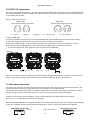
Play DMX Program --- Select this menu to run one of 10 programs which have been recorded via the menu
“Record DMX program”. By pressing the [ENTER] you can switch the running program into the 3 following modes:
Pause, Playing, Playing in Loop. The current program step is shown on the fixture display:
Record DMX Program --- The menu allows to record DMX data that receives the fixture and then replay them again
via the menu “Play DMX program”. There is a list of 10 programs for recording with unlimited steps each.
Select desired program number and press the [ENTER] to enter the recording screen.
The data record starts after changing any receiving DMX value. To stop recording, press [ENTER] or [ESC].
Recorded DMX program has the name dprg_xx.csv where the xx means the number of the program (e.g.
dpr_01.csv, dprg_02.csv....) and is stored in the folder “Programs” accessible by means of FTP. The format of this
file is a plain text that allows additional user editing. The first line of the file includes all DMX channels with their
starting DMX values and the next lines display changes of DMX values of channel effect and a relevant time of the
changes.
24
DigitalSpot 3000 DT II
Note: If you select the program which contains previously recorded data, the data will be overwritten without
warning.
Preset playback --- The menu allows to select a program (or a DMX program), which will be played automatically in
a loop after switching the fixture on.
Fixture Off Timer --- The menu offers to control the time during which the fixture is on and, for example, plays the
recorded program. The adjusted time period is counted from starting the fixture.
Timer Deactivated --- The item disables the “Fixture Off Timer” option.
Timer Activated --- Activate timer is signalled by the small icons at the top right corner of the screen.
Set Timer Hours --- The item enables to set hours for the “Fixture Off Timer”.
Set Timer Minutes --- The item enables to set minutes for the “Fixture Off Timer”.
15.7 Preview mode.
This item enables to display the image, going from the projector, on the fixture´s display.
Note: If this function is called out ,the video sequence from projector will not be played continuously because the
fixture´s processor has to display this sequence twice at the same time ( on the wall and on the display)
15.8 Reset functions
The DigitalSpot 3000 DT II can be reset totally or in function modules. Select a desired function to run a reset:
Reset Graphics Engine --- This function resets a graphics engine.
Reset Pan/Tilt System --- This function resets a pan/tilt movement.
Reset Focus/Shutter system --- This function resets a focus module.
Reset All systems --- This function enables you to return all fixture´s effects to their standard positions.
15.9 Service menu
Use this menu to read useful information about the fixture.
Power On Time - Select this submenu to read the number of operation hours of the fixture.
Total Hours - The function shows the total number of the operation hours since
the DigitalSpot 3500 has been fabricated.
Resetable Hours - The function shows the number of the operation hours that
the DigitalSpot 3500 has been powered on since the counter was last reset. In order
to reset this counter to 0, press [ENTER] twice.
Lamp On Time - Select this submenu to read the number of the operation hours with the projector lamp on.
Total Hours - The function shows the total number of the operation hours with the lamp
on since the DigitalSpot 3500 has been fabricated.
Resetable Hours - The function shows the number of the operation hours with the
lamp on that the DigitalSpot 3500 has been powered on since the counter was last reset.
In order to reset this counter to 0, press [ENTER] twice.
Lamp Strikes - Select this submenu to read the total number of the projector lamp strikes.
Total Hours - The function shows the total number of the lamp strikes since
the DigitalSpot 3500 has been fabricated.
Resetable Hours - The function shows the number of the lamp strikes since
the counter was last reset. In order to reset this counter to 0, press [ENTER] twice.
Fixture Temperatures --- Select this submenu to read the temperatures of the projector:
Current - Select this function to read the current temperatures of the fixture interior .
Maximum nonresetable -The function shows the max. temperatures of the fixture interior
since the DigitalSpot 3000 DT II has been fabricated.
Maximum resetable - The function shows the maximum temperatures of the fixture interior
25
DigitalSpot 3000 DT II
since the respective counter was last reset. In order to reset desired counter to 0,
press [ENTER] twice.
Measuring points of temperatures:
Pan /Tilt Board. [°C] ...............temperature on the PCB in the fixture base
Led Panel Board [°C]................temperature in the LED module
Air Filters --- Regular cleaning of the air filters is very important for the DigitalSpot 3000 DT II life and performance.
Buildup of dust, dirt and fog fluid residues reduces the fixture´s light output and cooling ability. The two items of
menu help you to keep cleaning period of the air filters.
Time To Cleanup Filters - The option allows you to read the time which remains to
cleaning air filters. Expired time period is signalized by a negative mark at the time value and
a warning icon (triangle) on the display with the following message:
"Please , Clean Up Airs Filters."
Clean the filters and reset this menu item (by pressing the "Enter" button twice while
this menu is highlighted)
Set Cleanup Timer - Cleaning schedule for the fixture depends on the operating
environment. It is therefore impossible to specify accurate cleaning interval. This function
allows you to change the cleaning interval of the air filters. This "reminder" value is
50 hours and it is set as default. Inspect fixture within its 50 hours of operation to see
whether cleaning is necessary. If cleaning is required, clean all air filters and change
the value in this menu on acceptable level. Min. level is 10 hours, max. is 300 hours.
15.10 Special functions
Use this menu for special services like remote servis or software update.
Regenerate Thumbnails --- Use the menu to manage thumbnails behaviour.
Set Thumbnail size - The menu item allows set the size of the thumbnail: 50-min.size,
300-max.size.
Regenerate Thumbnails - By pressing the "Enter" button the refreshing process
of gobo/video thumbnails starts. This action should be performed if you have changed
gobo/video files and the fixture was not switched off after the change , otherwise the
refreshing process runs automatically at starting up of the DigitalSpot 3000 DT II.
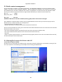
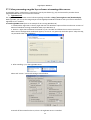
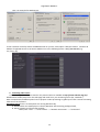
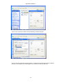
FTP Server --- The FTP (File Transfer Protocol) server is used to transfer files between the fixture and a PC over an
ethernet network by means of FTP client running on your PC. The "FTP Server" menu allows control of an access to
the fixture´s folders.
Set Account - The option allows you to protect the access to the fixture folders by setting
the name and password. The same data must be entered in FTP terminal running on
your PC.
Allow Anonymous - If this option is set "Yes" ,no password is required in FTP terminal but
the user name may be "ftp" or "anonymous".
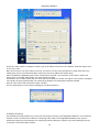
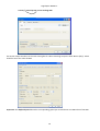
HTTP Access --- This menu enables to set access privileges which are used at entering to the Remote
control program via your WWW browser.
Set Account - The option allows you to protect the access to the Remote control
program by setting the name and password. The same data must be used in the Remote
control program running on your PC or a light control console.
Allow Anonymous - If this option is set "Yes" ,no password is required at entering to
the Remote control program.
USB Data Synchronization --- The menu allows transfer of media files (images, videos) and software files between
the USB stick and fixture´s hard disk and related operations.
The USB stick must contain the following folders structure:
26
DigitalSpot 3000 DT II
Top level folder
Media
000
001
002
:
240
Programs
Update
Log
:
To create the folders structure mentioned above, use the option "Init Flash Disc". After creating folders structure
on the USB stick you may load/download files into folders/subfolders .Maximum number of media files in one
Media subfolder is 240. Subfolders 000-020 are reserved for default images/videos and cannot be changed (you
cannot copy media files into these subfolders).
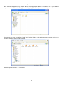
To upload a file/folder from the USB stick to the Media folder in the fixture:
1. Insert the USB stick to the USB port , select "USB Data Synchronize" from the menu and press the
[ENTER], "USB1" or "USB2" (depends on used USB port) is displayed on the screen.
2. Press the [ENTER], select "Open", press the [ENTER].
3. Select "Media", press the [ENTER],
4. If you want to copy all Media folder (including subfolders 000-240), select item "Synchronize to Fixture". If you
want to copy only one subfolder (e.g. 035) ,select "Open", press the [ENTER] , select desired subfolder from a list
of subfolders ,press the [ENTER] and select option "Synchronize to Fixture". If you want to copy only one file,
select "Open" and press the [ENTER]. Select the desired file, press the [ENTER] and confirm a question in a dialogue
box.
To download folder from the Media folder to the USB stick.
1. Insert the USB stick to the USB port , select "USB Data Synchronize" from the menu and press
the [ENTER]. "USB1" or "USB2" (depends on used USB port) is displayed on the screen.
2. Press the [ENTER], select Open, press the [ENTER].
3. Select "Media", press the [ENTER],
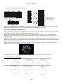
4. If you want to copy all Media folder from the fixture (including subfolders 000-240), select item "Synchronize
from Fixture". If you want to copy only one subfolder (e.g. 035) ,select "Open", press the [ENTER] , select desired
subfolder from a list of subfolders ,press the [ENTER] and select option "Synchronize from Fixture". If you want to
copy only one file, select "Open" and press Enter. Select the desired file, press the [ENTER] and confirm a question
in a dialogue box.
Software Update --- This menu allows to update graphical software or hardware processors software.
You have to download the latest version of the DigitalSpot 3000 DT II software from ROBE website to your hard
disk and then use either Ethernet network or the USB stick to move this file to the relevant folder in the
DigitalSpot 3000 DT II.
Copying software update file from the USB stick to the fixture:
1. Insert the USB stick to the USB port, select "USB Data Synchronize" from the menu and press
Enter. There is an USB1 or USB2 (depends on used USB port) displayed on the screen.
2. Press Enter, select Open, press the [ENTER].
3. Select Update and press the [ENTER]. If you want to upload whole Update folder to the fixture, select option
"Synchronize to Fixture".
If you only want to copy one or more files to the fixture, select option "Open" and press the [ENTER]. Select
desired file, press the [ENTER] and confirm a question in a dialogue box.
After copying update file to the fixture, the desired software update will be activated by confirming the
follow items:
Update Graphical Software - starts update of the graphical software.
If the message Please Update HW Processors in Menu "Special Functions" will appear
27
DigitalSpot 3000 DT II
after updating, run update of the hardware functions.
Update HW processors Software - starts update of hardware functions like pan, tilt,
focus...etc.
Update Media Content - starts update of the factory media folders 00-20 (pictures, videos)
Calibrate Values --- This menu serves for a fine calibration of effects.
Analog Shutter - allows ine calibration of a mechanical shutter (projector lamp has to be
turned on).
Tilt Calibration -allows fine calibration of a tilt.
Generate Log File --- This item starts generating a log file. The file is saved in a folder "Log" on the hard disk.
This file records events in a certain scope in order to provide an audit trail that can be used to diagnose problems
of the fixture.
Remote servis --- This menu provides necessary items for remote servis of the DigitalSpot 3000 DT II.
15.11 Fixture Off
This function shuts down the fixture. The projector lamp is switched off as first and after cca 20 seconds is switched
off the fixture.
16. Keystones
16.1 Global keystone parameters
If an image is output from the DigitalSpot 3000 DT II at an angle the image may be skewed. Eight keystone channels
(KeyStone Top Left X, KeyStone Top Left Y, KeyStone Top Right X, KeyStone Top Right Y, KeyStone Bottom Right X,
KeyStone Bottom Right Y, KeyStone Bottom Left X, KeyStone Bottom Left Y) adjust the image shape.It is possible to
control each of the four corners of the image and reshape it.
Default DMX value is 0, it means that no keystone correction has been used.
Setting all keystone values to 0 will place all four corners of the image at the four corners of the projector output.
The keystone values can also be used to create interesting skewing effects.
For the picture merging are important both the KeyStone X-ratio and KeyStoneY-ratio channels for correction of
the image distortion caused by placing projectors at different distances from the final image:
28
DigitalSpot 3000 DT II
use channel KeyStone X-ratio for correction
use channel
KeyStone Y-ratio
for correction
If the channel Global effect 1 - Parameter 3 is set to the range of 171-180, the aspect ratio of an actual image is
displayed in the image. The feature is activated when the Picture Merging is active only.
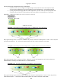
16.2 Layer keystone parameters
By the global keystone parameters stated above you can control each of the four corners of the graphics output
individually to reshape your image to a form that is projected correctly.
By the layer keystone parameters you can control all four corners of the image at the same time. With these
parameters you can create the same skewing and shape effects like with the global keystone parameters but on
each gobo layer.
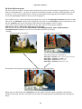
Major use of these effects is in a situation where the gobo mask is applied on a layer and you need to adjust a mask
shape onto some object on the scene. More important is adjusting of the inner part of the image on the layer than
the outer shape of the graphics output.
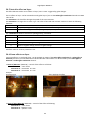
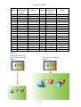
Characteristic case is a composition of 2 layers: the layer 1, where is applied a picture of the landscape and the
layer 2, where is a gobo mask selected (see picture below).
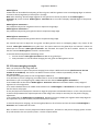
To adjust desired image shape you can use the following (keystone) parameters on the gobo layer 2:
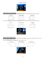
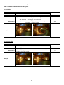
1. Layer zoom in X and Y direction.
The channels Gobo zoom X coarse and Gobo zoom X fine allow 8-bit/16-bit zooming in X-direction.
The channels Gobo zoom Y coarse and Gobo zoom Y fine allow 8-bit/16-bit zooming in Y-direction.
29
DigitalSpot 3000 DT II
2. Gobo position in X and Y direction.
The channels Gobo position X coarse and Gobo position X fine allow 8-bit/16-bit positioning in X-direction.
The channels Gobo position Y coarse and Gobo position Y fine allow 8-bit/16-bit positioning in Y-direction.
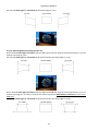
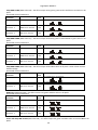
3. Layer skewing along X and Y axis.
On the channel Gobo effect 1 selection adjust a DMX value=150 and using the control parameters 1 an 2 you can
skew the image in either X or Y axis.
The channel Gobo effect 1 – Parameter 1 skews the image in X-axis.
30
DigitalSpot 3000 DT II
The channel Gobo effect 1 – Parameter 2 skews the image in Y-axis.
4. Layer Squeezing/Stretching along X and Y axis.
On the channel Gobo effect 1 selection adjust a DMX value=150 and using the Control Parameters 3 you can
squeeze the image in X axis.
The channel Gobo effect 1 – Parameter 3 squeezes/stretches the image edges in Y-axis.
On the channel Gobo effect 2 selection adjust a DMX value=150 and using the control parameters 1 you can
squeeze the image in Y axis. Note. To allows this effect, the channel Gobo effect 1 selection has to be set to
DMX=150.
The channel Gobo effect 2 – Parameter 1 squeezes/stretches the image edges in X-axis.
31
DigitalSpot 3000 DT II
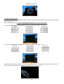
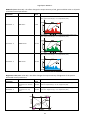
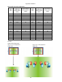
5. Image X-ratio and Y-ratio.
On the channel Gobo effect 2 selection adjust a DMX value=150 and the second and third parameter control image
X-ratio and Y-ratio.
Note. To allows this effect, the channel Gobo effect 1 selection has to be set at DMX=150.
The channel Gobo effect 2 – Parameter 2 compresses or expands the image in X- axis
The channel Gobo effect 2 – Parameter 3 compresses or expands the image in Y- axis.
After shaping the image by means of the parameters stated above, you can apply the global banner effects on the
whole graphics output and this final image should appear for instance like this:
32
DigitalSpot 3000 DT II
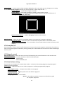
17. In Frame and Out Frame parameters
You can select any segment of a video file for playback by assigning parameters for In Frame (start point) and an
Out Frame (end point) as pictured below.
The In Frame parameter corresponds to a 16-bit DMX value equal to a starting point for the playback segment of
the selected video file. The Out Frame parameter corresponds to a 16-bit DMX value equal to an end point for the
playback segment of the selected video file.
1.Assigning the In Frame DMX values to 0
and Out Frame DMX values to 255 you will
playback the entire video file.
2. You can create a segment anywhere
between the beginning and the end of the
video file.
3. It is possible to skip a segment in the
video file by setting the In Frame to a point
following the Out Frame value.
18. Video Control
The channel Gobo control defines how the current layer will be ‘composed’ with the previous layers and the
playback options in each mode .The Digital Spot 3500 supports the following options:
Copy mode (0-17 DMX): In this mode, the pixels of the layer are written on top of the previous layers.
Addition mode (20-37 DMX: In this mode, the pixel values of the current layer are added to the ones of
the previous layers. This means that “dark” pixels in the current layer image won’t alter the pixels
that are underneath while “light” pixel will saturate the image underneath.
Subtraction mode (40-47DMX): In this mode, the pixel values of the current layer are subtracted from the pixel
value in the underlying layers. Dark pixel from the current layer won’t alter the pixel of
the layers underneath while light pixel will darken them.
Multiplication mode (60-77 DMX): In this mode, the pixels from the current layer will be multiplied by the pixels of
the underlying layers. For a pixel to appear bright in the output, the equivalent pixel of
the current layer and the underlying layer needs to be bright. If any of the layers has
a dark pixel, the result will be dark.
Minimum mode (80-97 DMX): This mode takes the pixel that is the darkest between the current layer and
the layer underneath
Maximum mode (100-117 DMX): This mode takes the pixel that is the brightest between the current layer and
the layer underneath.
33
DigitalSpot 3000 DT II
The playback options:
DMX value
Playback options
Meaning
0.
Play forward continuously if dimmer >0 Plays the video segment from In Frame point to
Out Frame point, continuous looping. The dimmer
value has to be greater than 0.
1
Play forward once if dimmer >0
Plays the video segment from In Frame point to
Out Frame point and holds on the last frame.
The dimmer value has to be greater than 0.
2
Pause
Stops playback of video file at the current playing
3
Play forward in continuous loop
Plays the video segment from In frame point to Out
Frame point, looping continuously
frame
Plays the video segment from In Frame point to Out
Frame point and holds on the last frame
4
Play forward once
6
Scrub (display) the selected In Frame
7
Scrub (display) the selected Out Frame Displays the frame which has been defined by
the Out Frame value.
Displays the frame which has been defined by
the In Frame value.
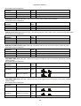
19. Playback speed
The Playback speed channel controls the speed of video playback at selected playback options.
DMX value
Playback speed
Meaning
0 or 128
Normal speed
Plays back video files at the original record. speed
1-127
Slow speeds from slowest to normal Plays back video files at an increasing speed,
from the slowest to the original recorded speed
129-255
Faster than normal to fastest
Plays back video files at an increasing speed,
from faster than normal to the fastest
34
DigitalSpot 3000 DT II
20. Graphic effects
There are two gobo effect channels on each gobo layer (Gobo effect 1 selection, Gobo effect 2 selection), which
offer amount of effects that can be applied to the current running picture/video. Each effect channels have three
control channels - Parameter 1, Parameter 2, Parameter 3 – which allow to change the behaviour of selected
effect (e.g. speed, amount...)
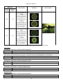
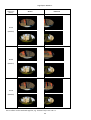
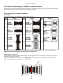
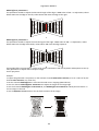
20.1 Kaleidoscopic effect
The kaleidoscopic effect section on the channel Gobo effect 1 selection allows selection of the static or dynamic
mode of the kaleidoscopic effect according to the desired mosaic segment.
DMX value
Static
mode
Dynamic
mode
Segment of mosaic
Example
Square
100
101
Right triangular
102
103
Isosceles triangular
104
105
Triangular 1
106
107
Triangular 2
108
109
35
Source picture
DigitalSpot 3000 DT II
DMX value
Static
mode
Dynamic
mode
Mosaic effect
Examples
Source picture
Centered Kaleidoscope
(rough)
110
111
Note: As the effect does
not cover all projection
are, the image from the
lower layer can be
displayed at the sides of
the effect.
E.g. Centered
Kaleidoscope effect has
been selected on the layer
4 and the picture on the
layer 3 is visible at the
sides of the effect.
Centered Kaleidoscope
(fine)
112
113
Note: As the effect does
not cover all projection
are, the image from the
lower layer can be
displayed at the sides of
the effect.
E.g. Centered
Kaleidoscope effect has
been selected on the layer
4 and the picture on the
layer 3 is visible at the
sides of the effect.
Meaning of the control channels depends on the kaleidoscope mode which has been selected:
Static mode.
Gobo effect 1- Parameter 1: Density of mosaic segments
DMX value
Function
0 - 255
Density of mosaic segments from large (0 DMX) to small (255 DMX)
If the effect “Centered Kaleidoscope (rough)” is selected, meaning of the Parameter 1 is the following:
DMX value
Function
0 - 255
Shape (diamond (0 DMX) circle (255 DMX)) and a number of mirroring planes
Gobo effect 1- Parameter 2: Content of segments-coarse
DMX value
Function
0 - 255
Coarse adjustment of the segments content
Gobo effect 1- Parameter 3 : Content of segments-fine
DMX value
Function
0 - 255
Fine adjustment of the segments content
Dynamic mode.
Gobo effect 1- Parameter 1: Density of mosaic segments
DMX value
Function
0 - 255
Adjusting density of mosaic segments from large (0 DMX) to small (255 DMX)
36
DigitalSpot 3000 DT II
If the effect “Centered Kaleidoscope (fine) ” is selected, meaning of the Parameter 1 is the following:
DMX value
Function
0 - 255
Shape and a number of mirroring planes
Gobo effect 1- Parameter 2: Size and pulsation of the segments content
DMX value
Function
0 - 128
Size of segments content from small (0 DMX) to large (128 DMX)
129 - 255
Speed of segment pulsation from slow (129 DMX) to fast (255 DMX)
Gobo effect 1- Parameter 3: Movement of the segments content
DMX value
Function
0 - 127
Backward movement of segments content from fast (0 DMX) to slow (127 DMX)
128
No movement
129-255
Forward movement of segments content from slow (129 DMX) to fast (255 DMX)
20.2 Circular effect (Fish eye)
The effect allows to convert a picture from an oblong format to a circle format and adjust the character of the
circular effect.
The circular effect can be activated on each gobo layer if you set the Gobo Effect 1 Selection channel to a DMX
Value of 90. The Parameter 1 of this effect changes the character of the circular effect from concave to convex.
The Parameter 2 and Parameter 3 serve for adjusting X ratio and Y ratio of the source image. A default value for all
three parameters is 128.
Control parameters:
Control
parameter
Parameter 1
Parameter 2
Parameter 3
Controlled item
Character of the
circular effect
X-ratio of the image
Y-ratio of the image
DMX
value
0-255
Function
0-255
0-255
continual adjustment
continual adjustment
concave (0) no adjustment (128) convex (255)
20.3 RGB (CMY) effects
The RGB effects section on the channel Gobo effect 2 selection allows to apply a variety of RGB colour swapping
effects to graphic objects.
RGB subtract All Pixels (DMX value=50) – the effect reduces colour values across all pixels.
37
DigitalSpot 3000 DT II
Associated control parameters:
Control
parameter
Parameter 1
Parameter 2
Parameter 3
Controlled item
Red colour element
Green colour element
Blue colour element
DMX
value
0-255
0-255
0-255
Function
no adjustment minimum saturation
no adjustment minimum saturation
no adjustment minimum saturation
RGB add All Pixels (DMX value=51) – the effect increases colour values across all pixels.
Associated control parameters:
Control
parameter
Parameter 1
Parameter 2
Parameter 3
Controlled item
Red colour element
Green colour element
Blue colour element
DMX
value
0-255
0-255
0-255
Function
no adjustment maximum saturation
no adjustment maximum saturation
no adjustment maximum saturation
RGB add non-black Pixels (DMX value=52) – the effect increases colour values across all pixels except black pixels.
Associated control parameters:
Control
parameter
Parameter 1
Parameter 2
Parameter 3
Controlled item
Red colour element
Green colour element
Blue colour element
DMX
value
0-255
0-255
0-255
Function
no adjustment maximum saturation
no adjustment maximum saturation
no adjustment maximum saturation
RGB subtract/add All Pixels (DMX value=53) – the effect reduces/ increases colour values across all pixels.
Associated control parameters:
Control
parameter
Parameter 1
Parameter 2
Parameter 3
Controlled item
Red colour element
Green colour element
Blue colour element
DMX
value
0-255
0-255
0-255
Function
Min. saturat. (0) no adjustment (128) max. saturation(255)
Min. saturat. (0) no adjustment (128) max. saturation(255)
Min. saturat. (0) no adjustment (128) max. saturation(255)
Swap RGB to RBG (DMX value=54) – the effect swaps green and blue colour in all pixels. Red colour remains
without change.
Associated control parameters:
Control
parameter
Parameter 1
Controlled item
Red colour element
DMX
value
0-255
Parameter 2
Green colour element
0-255
Parameter 3
Blue colour element
0-255
Function
No change.
no adjustment (0 ) blue (255)
no adjustment (0 ) green (255)
Swap RGB to GRB (DMX value=55) – the effect swaps red and green colour in all pixels. Blue colour remains
without change.
Associated control parameters:
Control
parameter
Parameter 1
Controlled item
Red colour element
DMX
value
0-255
Parameter 2
Green colour element
0-255
Parameter 3
Blue colour element
0-255
Function
no adjustment (0 ) green (255)
no adjustment (0 ) red (255)
No change.
38
DigitalSpot 3000 DT II
Swap RGB to GBR (DMX value=56) – the effect swaps red to green, green to blue and blue to red colour in all
pixels.
Associated control parameters:
Control
parameter
Parameter 1
Controlled item
Red colour element
DMX
value
0-255
Parameter 2
Green colour element
0-255
Parameter 3
Blue colour element
0-255
Function
no adjustment (0 ) green (255)
no adjustment (0 ) blue (255)
no adjustment (0 ) red (255)
Swap RGB to BRG (DMX value=57) – the effect swaps red to blue, green to red and blue to green colour in all
pixels.
Associated control parameters:
Control
parameter
Parameter 1
Controlled item
Red colour element
DMX
value
0-255
Parameter 2
Green colour element
0-255
Parameter 3
Blue colour element
0-255
Function
no adjustment (0 ) blue (255)
no adjustment (0 ) red (255)
no adjustment (0 ) green (255)
Swap RGB to BGR (DMX value=58) – the effect swaps red and blue colour in all pixels. Green colour remains
without change.
Associated control parameters:
Control
parameter
Parameter 1
Controlled item
Function
Red colour element
DMX
value
0-255
Parameter 2
Green colour element
0-255
No change.
no adjustment (0 ) red (255)
Parameter 3
Blue colour element
0-255
no adjustment (0 ) blue (255)
RGB invert (DMX value=59) – the effect inverts red, green and blue colour in all pixels.
Associated control parameters:
Control
parameter
Parameter 1
Controlled item
Red colour element
DMX
value
0-255
Parameter 2
Green colour element
0-255
Parameter 3
Blue colour element
0-255
Function
no adjustment (0 ) full inversion (255)
no adjustment (0 ) full inversion (255)
no adjustment (0 ) full inversion (255)
Invert and swap RGB to BRG (DMX value=60) – the effect swaps red, green and blue colour to inverted BRG in all
pixels.
39
DigitalSpot 3000 DT II
Associated control parameters:
Control
parameter
Parameter 1
Controlled item
Red colour element
DMX
value
0-255
Parameter 2
Green colour element
0-255
Parameter 3
Blue colour element
0-255
Function
no adjustment (0 ) full inverted blue (255)
no adjustment (0 ) full inverted red (255)
no adjustment (0 ) full inverted green (255)
Invert and swap RGB to GBR (DMX value=61) – the effect swaps red, green and blue colour to inverted GBR in all
pixels.
Associated control parameters:
Control
parameter
Parameter 1
Controlled item
Red colour element
DMX
value
0-255
Parameter 2
Green colour element
0-255
Parameter 3
Blue colour element
0-255
Function
no adjustment (0 ) full inverted green (255)
no adjustment (0 ) full inverted blue (255)
no adjustment (0 ) full inverted red (255)
Colour to Alpha (DMX value=62) – the effect changes the transparency level of an image´s element colour values.
You can adjust the transparency of individual colours from completely transparent to full opacity using the control
parameters 1, 2 and 3:
Control
parameter
Parameter 1
Parameter 2
Parameter 3
Controlled item
Red colour element
Green colour element
Blue colour element
DMX
value
0-255
0-255
0-255
Function
Changes the red colour element transparency
Changes the green colour element transparency
Changes the blue colour element transparency
Colour to Alpha Inverted (DMX value=63) – the effect changes the transparency level of the inverse of an image´s
element colour values.
Associated control parameters:
Control
parameter
Parameter 1
Parameter 2
Parameter 3
Controlled item
Red colour element
Green colour element
Blue colour element
DMX
value
0-255
0-255
0-255
Function
Changes the inverted red colour element transparency
Changes the inverted green colour element transparency
Changes the inverted blue colour element transparency
40
DigitalSpot 3000 DT II
RGB scale (DMX value=68) – the effect changes the output intensity of red, green and blue colour in all pixels.
Associated control parameters:
Control
parameter
Controlled item
DMX
value
Function
Changes the inclination of conversion line for red colour from
max. output intensity (0 ) no adjustment (255)
Parameter 1
Red colour
0-255
Changes the inclination of conversion line for green colour from
max. output intensity (0 ) no adjustment (255)
Parameter 2
Green colour
0-255
Changes the inclination of conversion line for blue colour from
max. output intensity (0 ) no adjustment (255)
Parameter 3
Blue colour
0-255
Brightness scale (DMX value=69) – the effect changes the output intensity of brightness of the picture.
Associated control parameters:
Control
parameter
Parameter 1
Parameter 2
Controlled item
Inclination of the
conversion line – bottom
point
Inclination of the
conversion line – top
point
DMX
value
Function
0-255
Changes the inclination of conversion line for output brightness
from no adjustment (0 ) min. brightness (255)
0-255
Changes the inclination of conversion line for output brightness
from max. brightness (0 ) no adjustment (255)
Example:
41
DigitalSpot 3000 DT II
20.4 Iris effect on layer
The effect allows to simplify transition effects between layers and it can be activated on each gobo layer. On the
effect can be applied layer´s X/Y zoom, X/Y position and rotation parameters. Another possible application of the
iris effect is to use it as the mask function to mask unwanted parts of the image. On the iris effect on the layer
can be also applied global effects as the iris, picture merging etc.
The iris effect on layer can be activated on each gobo layer if you set the Gobo Effect 1 Selection channel to a DMX
value of 91. The Parameter 1 of this effect changes the size of the iris. The Parameter 2 selects type of the iris and
the last Parameter 3 serves for selecting of several texture modes applied on the iris surface.
To see various texture modes, the channels of the X/Y zoom have to comply with a condition:
Gobo zoom X coarse > 128 and the Gobo zoom Y coarse>128.
After that you can use the channels Gobo position X coarse(Gobo position X fine)and Gobo position Y
coarse(Gobo position Y fine) to move the iris to the desired position on the layer.
Example:
Selected image on the layer 2:
Selected image on the layer 3:
+
Gobo effect selection on the layer 3:
Gobo effect 1 selection =91 (the effected has been activated)
Gobo effect 1- Parameter 1 = 158 (iris size)
Gobo effect 1- Parameter 2 = 2 (iris type)
Gobo effect 1- Parameter 3 = 5 (texture mode)
Visual effect on the projection screen when the Iris Effect On Layer is activated:
Below, there is a description of the Parameter 3 for each group of texture modes ( examples in the table are
stated for X-axis only, but the Y-axis behaves in the same). The original pictures on both gobo layers are figured
above.
42
DigitalSpot 3000 DT II
Gobo Effect 1-Parameter 3: Texture modes applied on the iris surface
Parameter 3
DMX value
(Mode)
Zoom X
Zoom X + Position X
0-9
(Mode 1)
10-19
(Mode 2)
20-29
(Mode 3)
30-39
(Mode 4)
The following modes (5-8) include black mask
40-49
Dimmer on the layer 3= 255 DMX
Dimmer on the layer 3= 255 DMX
(Mode 5)
Dimmer on the layer 3= 1 DMX
Dimmer on the layer 3= 1 DMX
43
DigitalSpot 3000 DT II
Parameter 3
DMX value
(Mode)
Zoom X
Position X
50-59
Dimmer on the layer 3= 255 DMX
Dimmer on the layer 3= 255 DMX
Dimmer on the layer 3= 1 DMX
Dimmer on the layer 3= 1 DMX
Dimmer on the layer 3= 255 DMX
Dimmer on the layer 3= 255 DMX
Dimmer on the layer 3= 1 DMX
Dimmer on the layer 3= 1 DMX
Dimmer on the layer 3= 255 DMX
Dimmer on the layer 3= 255 DMX
Dimmer on the layer 3= 1 DMX
Dimmer on the layer 3= 1 DMX
(Mode 6)
60-69
(Mode 7)
70-79
(Mode 8)
The iris effect can be combined together, e.g. between layers 3-2 and 2-1.
44
DigitalSpot 3000 DT II
20.5 Auto iris effect on layer
The effect behaves similar as Iris effect on layer, but it is auto- triggered by gobo changes.
The iris effect on layer can be activated on each gobo layer if you set the Gobo Effect 1 Selection channel to a DMX
value of 92.
The Parameter 1 of this effect changes the speed of the iris movement.
The Parameter 2 changes the iris mask type. The value of 254 and 255 activates random iris with the following
functions:
DMX value
Function
254
Every iris opening and closing is performed with different type of iris
255
Type of iris is changed after completing the open/close cycle
The Parameter 3 allows to choose iris opening/closing command:
DMX value
Function
0
Close iris
1
Open iris
2
3
Open and close iris at gobo change
Open iris at gobo change, close iris at gobo change
A default value for all three parameters is 0.
20.6 Zoom effects on layer
Two zoom effects on each gobo layer can be applied on images if the Gobo Effect 1 Selection (or Gobo Effect 2
Selection) channel is set to a DMX value of 95 and 96. Both zoom effects can be activated by the Gobo Effect 1
Selection or Gobo Effect 2 Selection channel.
1. Zoom In/Move XY
Parameter 1
Parameter 2
Parameter 3
Example:
original picture
(DMX=95) – control of the effect is as follows:
– zoom factor
– movement in X-axis
– movement in Y-axis
after applying the effect
2. Zoom In/Auto Move XY (DMX=96) – control of the effect is following:
Parameter 1 – zoom factor
Parameter 2 –speed in X-axis
Parameter 3 – speed in Y-axis
45
DigitalSpot 3000 DT II
20.7 Another graphic effects on layers
1. Swirl effect
Activation channel
Activation DMX value
Control: Parameter 1
Parameter 2
Parameter 3
Gobo Effect 2 Selection (on each layer)
70
Radius: 0-255DMX
- min. max
Angle: 0-127DMX
- turning by 360° to the right
128 DMX
- no change
129-255 DMX
-turning by 360° to the left
Diagonal position: 0-255DMX – top left corner bottom right corner
128 DMX - center of image
Original
Default value
0
128
128
P1=111DMX, P2=84DMX, P3=138DMX
Example
2. Pixelation effect
Activation channel
Activation DMX value
Control: Parameter 1
Parameter 2
Parameter 3
Gobo Effect 2 Selection (on each layer)
71
Amount of pixel in X-axis: 0-255DMX
- max. min.
Amount of pixel in Y-axis: 0-255DMX
- max. min.
Effect boundary position in X-axis: 0-255 DMX – movement of effect
boundary from left to right
Original
P1=27DMX, P2=27DMX, P3=138DMX
Example
46
Default value
0
0
0
DigitalSpot 3000 DT II
3. Cross-stitching effect
Activation channel
Activation DMX value
Control: Parameter 1
Parameter 2
Parameter 3
Gobo Effect 2 Selection (on each layer)
72
Pattern density: 0-255 DMX
- max. min.
Colour of stitch: 0-127 DMX
- coloured
128-255 DMX
- black
Effect boundary position in X-axis: 0-255 DMX – movement of effect
boundary from left to right
Original
P1=81DMX, P2=0DMX, P3=85DMX
Default value
0
0
0
P1=81DMX, P2=128DMX, P3=85DMX
Example
4. Posterization effect
Activation channel
Activation DMX value
Control: Parameter 1
Parameter 2
Gobo Effect 2 Selection (on each layer)
73
Number of colours: 0 DMX
- all colours
1-255DMX
- reducing of colours
Gamma correction: 0-255DMX
- min. max.
Original
P1=228DMX, P2=0DMX
Example
47
Default value
0
0
DigitalSpot 3000 DT II
21. Media content management
As you seen earlier in chapter "12. Folder organization", the DigitalSpot 3000 DT II uses the root folder named
"Media". This folder contains subfolders (000,001...240) and inside each subfolder is the collection of media that
the subfolder holds. The files in subfolders are sorted in an alphabetic or numerical order and assigned to DMX.
The first part of the file name should be a 3-digit number followed by an underscore and a name e.g.:
001_sun..................... 1 DMX
002_snow_castle........2 DMX
:
255_apple................255 DMX
Subfolders 000-020 are reserved for default (factory) gobos/videos and cannot be changed.
User subfolders 21-240 and their contents can be mowed between fixtures and your local drive (PC) as well as
between fixtures. Which method you use depends on:
- how much content you want to move
- whether the fixture is currently connected to the Ethernet fixture link
There is several methods for moving user content files and folders between fixtures and a local drive and between
fixtures each other. You can use:
- FTP client in Windows explorer window (fixtures have to be connected to Ethernet link)
- FTP client in Mozilla Firefox (fixtures have to be connected to Ethernet link)
- USB stick
- option "Contents Synchronization" in a Remote control program (fixtures have to be connected to Ethernet link).
For detail description see articles below.
21.1 Moving files between the fixture and a PC
1. FTP client in explorer window
All fixtures have to be linked to the Ethernet link. The proper network configuration and IP address setting of your
PC is very important. The following is an example of an IP setting for Windows XP :
48
DigitalSpot 3000 DT II
After network configuration, type the IP address of the DigitalSpot 3000 DT II in address line in your Windows
explorer window. Use this format ftp:// 2.X.X.X / (e.g. ftp://2.236.2.88/- see picture below).
If all settings are proper, you will see "Media" and "Update" folders in the Windows explorer window and now you
can work with them as local folders and files.
See also "Special functions"--> "FTP Server".
49
DigitalSpot 3000 DT II
2. FTP client in Mozilla Firefox
If you use Mozilla Firefox as your web browser, you can install FTP client into the browser.
To install FTP client for Mozilla Firefox on your computer.
1. Run Mozilla Firefox.
2.Select option “ Tools” from the Menu bar, select “Add-ons” item.
3.Select option “Get Add-ons” from the standard toolbar, type fireftp into the top left field and press Enter key.
4.Click on the Add to Firefox.. button and follow the installation instructions.
5. Follow the installation instructions until the installation has finished.
5.After installation, go to the “ Tools”, select “Add-ons” item, select “Extensions” in the toolbar and click on the
Options button. Select “Interface” menu and check option “Configure FTP links in Firefox to automatically use
FireFTP”.
50
DigitalSpot 3000 DT II
After installing FTP client, run Mozilla Firefox and type the IP address of desired fixture in ftp format e. g.
ftp://2.97.181.89 and a Fire FTP window will appear.
If you do not want to keep in mind IP addresses of all connected fixtures, you can use the Remote configuration
program (by typing the IP address of one fixture to the web browser in http format e. g. http://2.97.181.89) and
go to the Contents Synchronization window where a list of available fixtures is offered.
You need to know only IP address of one fixture as the rest of connected fixtures with their IP addresses is
displayed in this window. By clicking on the Ftp option (in parenthesis) at desired fixture the FireFTP window will
appear:
Now you can move files between PC and desired fixture.
3. Via USB stick
Next way, how to add or remove files from the media folders is by means of the USB stick - see "USB Data
Synchronization" in chapter "Special functions".
51
DigitalSpot 3000 DT II
21.2 Moving files between networked fixtures
The option "Contents Synchronization" in a "Remote control program" running on your PC offers easy control of
file transfer between networked fixtures via WWW browser. (For detail description of the Remote configuration
program see chapter "Remote control of the fixture via WWW browser" below).
A window of Contents Synchronization:
There is a list of available fixtures under Device Available for Update. If you connect another fixture to a network,
use option "Rescan Devices" to refresh the list of fixtures.
A list of available folders with their check boxes is placed under Synchronization Folders.
Option "Synchronization Mode" gives you possibility to select how the files will be moved to target folder:
"Mirror"- a content of the target folder will be fully overwritten by a content of the source folder.
"Add"- files from the source folder are added to existing files in the target folder.
The last folder "Update" next to the gobo folder no. 240 serves for a synchronization of the “update” folders
between the fixtures.
The last folder "Update" next to the gobo folder no. 240 serves for a synchronization of the “update” folders
between the fixtures
To move files.
1. Select desired folders check boxes. If you want to select all folders, check All Media check box.
2. Select a target fixture (fixtures) in a list of available fixtures.
3. Select desired Synchronization Mode and click the "Do Synchronization" button to start the file transfer.
22. Remote control of the fixture via WWW browser
The DigitalSpot 3000 DT II offers a remote control of the fixture and diplaying useful information about the fixture
including the gobo folders contents via WWW browser.
The fixtures has to be connected via an ethernet (with Art-Net communication protocol) to a network. The PC or
light console has to be connected to the same network as the fixtures. Use only the IP addresses which have first
number 2 like 2.X.X.X, e.g. 2.236.2.88.
To run a Remote control program type the IP address of the desired fixture to your WWW browser (e.g.
http://2.236.2.88) and the input window of the Remote Control will appear.
Note: if you wish to have access to this utility under password, use the menu "HTTP Access" in "Special functions"
to set a password.
The Remote Control screen offers these options:
Fixture Info - the window with information about current fixture address, disk space, software versions etc.
52
DigitalSpot 3000 DT II
Personality - the window allows you to change the fixture settings like a pan/tilt reverse,
feedback, speed, lamp status, DMX protocol selection etc.
Status Messages -the window under this option displays error and status messages.
Special Functions - the window offers several items:
"Thumbnails size" - changing the size of the thumbnails. The change takes effect in
the item "Content". If you change the thumbnail size, use the button "Update"
below the size box.
53
DigitalSpot 3000 DT II
"Log File" - enables to generate log file for service purposes.
"System Reboot"- starts reboot of the fixture
"Regenerate Video Headers"- allows to regenerate headers of video media files.
Content - by entering this window a complete overview of all gobo folders is offered, from which the
folder to be view can be selected.Click a desired folder to display its content.
Click a desired picture to zoom it in.
Contents Synchronization - the window allows you copy (addition) media content from
a current fixture to another fixtures on an ethernet network.
54
DigitalSpot 3000 DT II
There is a list of available fixtures under Device Available for Update. If you connect another fixture to a network,
use option "Rescan Devices" to refresh the list of fixtures.
A list of available folders with their check boxes is placed under Synchronization Folders.
Option "Synchronization Mode" gives you possibility to select the way how the files will be moved to target folder:
"Mirror"- a content of the target folder will be fully overwritten by a content of the source
folder.
"Add"- files from the source folder are added to existing files in the target folder.
The last folder "Update" next to the gobo folder no. 240 serves for a synchronization of the “update” folders
between the fixtures
To move files.
1. Select desired folders check boxes. If you want to select all folders, check "All Media" check box.
2. Select a target fixture (fixtures) in a list of available fixtures.
3. Select desired Synchronization mode and click the "Do Synchronization" button to start file transfer.
Remote Graphics Output - preview of the current projecting output.
Remote RNS Display - the window "takes" the fixture´s control panel. You can browse and adjust all items in this
fixture menu by means of your keyboard. Use the Up/Down and Enter/Escape keys.
Remote Content - the window offers a table for definition of streaming sources. Type a streaming protocol, an IP
address and a port number for the desired streaming source (e.g. laptop) to the first line in the following format:
55
DigitalSpot 3000 DT II
http://2.x.x.x:port number (for example http://2.1.1.3:1234)
and click the "Update" button on the right side of the line to save the streaming source address. This source is
assigned to the DMX value of 1 on channel Gobo selection. Up to 20 streaming sources is possible to define in this
way. All defined streaming sources are assigned to DMX values of the Gobo selection channel and can be used on
each gobo layer.
Previous channel Gobo folder selection has to be set at DMX value of 252 in order to allow the use of streaming
sources assigned to the Gobo selection channel. See the chapter”Streaming video”.
To end the Remote control program, close WWW browser ( or use option "Logout" if you entered the program
using the user name and password).
23. Picture merging
The picture merging system allows to create a panoramic projection controlled from a light DMX console.
The resulting seamless image consists of the images of the individual projectors. It is possible to create an
image field up to 64 segments ( non-mirrored configuration).
You can display the original DigitalSpot 3000 DT II gobos/videos or custom gobos/videos from user folders.
23.1 Picture merging control channels
Global effect 1
DMX values in a range of 1-7 enable the picture merging procedure. You can select from several predefined widths
of the picture overlapping edges (from 0 to 35%). In many cases the projection screen is smaller than the total
merged image of the projectors. This total image can be scaled either using Keystoning parameters or (better)
adjusting the width of blending areas.
DMX=2 (width=0%)
DMX=1 (width=10% )
DMX=7 (width=35% )
There are dot symbols in each corner of test pattern. The dot symbols correspond to the global keystone
parameters in the following way:
- KeyStone Top Left X/ KeyStone Top Left Y
- KeyStone Top Right X/ KeyStone Top Right Y
- KeyStone Bottom Right X/ KeyStone Bottom Right Y
- KeyStone Bottom Left X/ KeyStone Bottom Left Y
These symbols should make easy identification of appropriate keystones in case there is several parts of merged
picture.
56
DigitalSpot 3000 DT II
Global effect 1- Parameter 1
The DMX value from the range of 1- 235 allows selection of desired image field configuration according to the
tables on the following pages.
Image field configuration
Non-mirrored configuration
DMX
value
Image field
Configuration
WxH
Total number of
fixtures
DMX
value
Image field
Configuration
WxH
Total number of
fixtures
1
2x1
2
56
4x8
32
2
1x2
2
57
8x5
40
2
2x2
4
58
5x8
40
4
3x1
3
59
8x6
48
5
1x3
3
60
6x8
48
6
3x2
6
61
8x7
56
7
2x3
6
62
7x8
56
8
3x3
9
63
8x8
64
9
4x1
4
64
9x1
9
10
1x4
4
65
1x9
9
11
4x2
8
66
9x2
18
12
2x4
8
67
2x9
18
13
4x3
12
68
9x3
27
14
3x4
12
69
3x9
27
15
4x4
16
70
9x4
36
16
5x1
5
71
4x9
36
17
1x5
5
72
9x5
45
18
5x2
10
73
5x9
45
19
2x5
10
74
9x6
54
20
5x3
15
75
6x9
54
21
3x5
15
76
9x7
63
22
5x4
20
77
7x9
63
23
4x5
20
78
10 x 1
10
24
5x5
25
79
1 x10
10
25
6x1
6
80
10 x 2
20
26
1x6
6
81
2 x 10
20
27
6 x2
12
82
10 x 3
30
28
2 x6
12
83
3 x 10
30
29
6x3
18
84
10 x 4
40
30
3x6
18
85
4 x 10
40
31
6x4
24
86
10 x 5
50
32
4 x6
24
87
5 x 10
50
33
6x5
30
88
10 x 6
60
34
5x6
30
89
6 x 10
60
35
6x6
36
90
11 x 1
11
36
7x1
7
91
1 x 11
11
57
DigitalSpot 3000 DT II
DMX
value
Image field
Configuration
WxH
Total number of
fixtures
DMX
value
Image field
Configuration
WxH
Total number of
fixtures
37
1x7
7
92
11 x 2
22
38
7x2
14
93
2 x 11
22
39
2x7
14
94
11 x 3
33
40
7x3
21
95
3 x 11
33
41
3x7
21
96
11 x 4
44
42
7x4
28
97
4 x 11
44
43
4x7
28
98
11 x 5
55
44
7x5
35
99
5 x 11
55
45
5x7
35
100
12 x 1
12
46
7x6
42
101
1 x 12
12
47
6x7
42
102
12 x 2
24
48
7 x7
49
103
2 x 12
24
49
8x1
8
104
12 x 3
36
50
1x8
8
105
3 x 12
36
51
8 x2
16
106
12 x 4
48
52
2x8
16
107
4 x 12
48
53
8x3
24
108
12 x 5
60
54
3x8
24
109
5 x 12
60
55
8x4
32
-
-
-
Example
Image field configuration:
W x H =2 x 2 =4 projectors
DMX= 3
W x H =4 x 4 =16 projectors
DMX=15
58
DigitalSpot 3000 DT II
Horizontally mirrored configuration
DMX
value
Image field
configuration
of base matrix
WxH
Total number of
fixtures in base
matrix
DMX
value
Image field
configuration
of base matrix
WxH
Total number of
fixtures in base
matrix
128
2x1
2
146
10 x 2
20
129
4x1
4
147
4x5
20
130
2x2
4
148
10 x 3
30
131
4x2
8
149
6x5
30
132
6x1
6
150
10 x 4
40
133
2x3
6
151
8x5
40
134
6x2
12
152
10 x 5
50
135
4x3
12
153
12 x 1
12
136
6x3
18
154
2x6
12
137
8x1
8
155
12 x 2
24
138
2x4
8
156
4x6
24
139
8x 2
16
157
12 x 3
36
140
4x4
16
158
6x6
36
141
8x3
24
159
12 x 4
48
142
6x4
24
160
8x6
48
143
8x4
32
161
12 x 5
60
144
10 x 1
10
162
10 x 6
60
145
2x5
10
163
12 x 6
72
Example
Image field configuration:
W x H =2 x 2 =4 projectors
DMX= 130
W x H =4 x 4 =16 projectors
DMX=140
59
DigitalSpot 3000 DT II
Vertically mirrored configuration
DMX
value
Image field
configuration
of base matrix
WxH
Total number of
fixtures in base
matrix
DMX
value
Image field
configuration
of base matrix
WxH
Total number of
fixtures in base
matrix
164
1x2
2
182
5x4
20
165
2x2
4
183
2 x 10
20
166
1x4
4
184
5x6
30
167
2x4
8
185
3 x 10
30
168
3x2
6
186
5x8
40
169
1x6
6
187
4 x 10
40
170
3x4
12
188
5 x 10
50
171
2x6
12
189
6x2
12
172
3x6
18
190
1 x 12
12
173
4x2
8
191
6x4
24
174
1x8
8
192
2 x 12
24
175
4x4
16
193
6x6
36
176
2x8
16
194
3 x 12
36
177
4x6
24
195
6x8
48
178
3x8
24
196
4 x 12
48
179
4x8
32
197
6 x 10
60
180
5x2
10
198
5 x 12
60
181
1 x 10
10
199
6 x 12
72
Example
Image field configuration:
W x H =2 x 2 =4 projectors
DMX= 165
W x H =4 x 4 =16 projectors
DMX=175
60
DigitalSpot 3000 DT II
Vertically and horizontally mirrored configuration
DMX
value
Image field
configuration
of base matrix
WxH
Total number of
fixtures in base
matrix
DMX
value
Image field
configuration
of base matrix
WxH
Total number of
fixtures in base
matrix
200
2x2
4
218
10 x 4
40
201
4x2
8
219
4 x 10
40
202
2x4
8
220
10 x 6
60
203
4x4
16
221
6 x 10
60
204
6x2
12
222
10 x 8
80
205
2x6
12
223
8 x 10
80
206
6x4
24
224
10 x 10
100
207
4x6
24
225
12 x 2
24
208
6x6
36
226
2 x 12
24
209
8x2
16
227
12 x 4
48
210
2x8
16
228
4 x 12
48
211
8x4
32
229
12 x 6
72
212
4x8
32
230
6 x 12
72
213
8x6
48
231
12 x 8
96
214
6x8
48
232
8 x 12
96
215
8x8
64
233
12 x 10
120
216
10 x 2
20
234
10 x 12
120
217
2 x 10
20
235
12 x 12
144
Example
Image field configuration:
W x H =2 x 2 =4 projectors
DMX= 200
W x H =4 x 4 =16 projectors
DMX=203
61
DigitalSpot 3000 DT II
The mirrored image configurations bring 2 advantages:
1. Resolution of the source image and merged images on the wall is the same in comparison with
non-mirrored configuration (if you use suitable mirrored configuration – see example 3 below).
2. By using the picture merging with mirrored configuration you can cover any size of projection area.
The base matrix of fixtures can be repeated. The total number of used projectors is unlimited.
Examples: 4 DigitalSpots 7000DT are used in the picture merging.
Source picture
Aspect ratio: 4:3
Resolution: 1024 x 768
Images on the wall:
Example 1. Horizontally mirrored configuration 4 x 1 (DMX=129) set on all fixtures
All projected images have a resolution of 1024 x 768, but the resolution of 1024 pixels is “made ” from 512 pixels
as each fixture projects 1/2 of the source picture (this half has a source resolution 512 x 768).
Example 2. Horizontally mirrored configuration 2 x 1 (DMX=128) set on two pairs of fixtures
2x1
2x1
All projected images have a resolution of 1024 x 768 pixels and the total image does not have any distortion
(horizontally or vertically). The base matrix 2 x 1 is twice repeated.
Example 3. Non- mirrored configuration 4 x 1 (DMX=9) set on all fixtures
All projected images have resolution 1024 x 768, but the resolution of 1024 pixels is “made ” from 256 pixels as
each fixture projects ¼ of the source picture (this quarter has a source resolution 256 x 768).
62
DigitalSpot 3000 DT II
Global effect 1- Parameter 2
The DMX values from the range of 0-255 are used to step segment by segment throw the image grid. The DMX
value of 0 corresponds to the upper left segment of the image grid. The stepping runs from the left to the right
and down from top (see example for field 8x3 segments bellow).
Global effect 1- Parameter 3
This channel enables to transform displaying of the segment edges-sharp or blended edges. You can also display
the blue and red auxiliary frame with the alignment marks for easier alignment of the adjacent segments:
Channel
48
Value
0-130
131-140
141-150
151-160
161-170
171-180
181-255
Function
Type of control
Global effect 1 - Parameter 3
Displays segment with blended edges (active keystoning)
Displays segment with sharp edges (active keystoning)
Displays segment with sharp edges
Displays auxiliary patern frame with sharp edges (active keystoning)
Displays auxiliary patern frame, sharp edges
Showing aspect ratio of image projected on the wall
Reserved
To align segments use pan/tilt, zoom and keystones channels.
Segments before alignment:
step
step
step
step
step
step
Segments after alignment:
At adjacent edges there is the blue edge that overlaps the red one and respectively :
Note. DMX values of both channels Global effect 1 and Global effect 1- Parameter 1 have to be set at the same
values on all fixtures used in the picture merging.
If the channel Global effect 1 - Parameter 3 is set to the range of 171-180, the aspect ratio of an actual image is
displayed in the image. The feature is activated when the Picture Merging is active only. The value of the aspect
ration changes during setting of Keystone/zoom channels. The function is useful when the image is projected on
the skewed surface, at Picture Margin and at video projection (usually 16: 9 aspect ratio ).
Aspect ratio 4:3
Aspect ratio 16:9
63
DigitalSpot 3000 DT II
Global effect 2
A DMX value of 20 enables fine adjusting of the red, green and blue gamma curve at overlapping edges to achieve
consistent colour( brightness) of these parts of image.
Note. After selecting desired image segment for the gamma correction (by means of the Global effect 1 Parameter 2), set the channel Global effect 1 - Parameter 3 to 0 in order to display blended edges of the picture
segment.
Global effect 2- Parameter 1
The parameter adjust the red gamma value at respective image adge.
Global effect 2- Parameter 2
The parameter adjust the green gamma value at respective image adge.
Global effect 2- Parameter 3
The parameter adjust the blue gamma value at respective image adge.
The second way how to adjust the red, green and blue gamma curve at overlapping edges is by means of the
channel Gobo effect 2 Selection on a gobo layer. The option works on the global layer and it doesn´t matter on
which layer the channel Gobo effect 2 Selection was activated. This option can be a suitable solution in a case
that the channel Global effect 2 is used for another effect.
To activate the fine adjustment of blending curves.
1. Set the channel Gobo effect 2 selection to 200 on any gobo layer .
2. Now parameters 1-3 of this effect changing the red, green and blue gamma curves.
23.2 Picture merging example
Here is an example of the image field 3x2.
1. All fixtures that are a part of the picture merging have to have a different fixture ID (The fixture ID= the last
number of its IP address). The fixture´s IP address consists of four numbers separated by the dot e.g.
002.168.002.010.
2. Select the same gobo/video on the six DigitalSpots 3000 DT II.
3. On all fixtures you are configuring set a DMX value=1 at the channel Global Effect 1.
On all fixtures you are configuring set a DMX value=6 at the channel Global Effect 1-Parameter 1.
4. Set a DMX value at the channel Global Effect 1- Parameter 3 between 151-160 to define a sharp edges of
segments for a fine alignment.
5. On each individual fixture set a DMX value between 0-5 at Global Effect 1 - Parameter 2 to select the segment
that the fixture will project.
6. Use pan/tilt/zoom and keystone channels to align the projections of individual fixtures in such a way that there
is some overlap between the separate portions of the image. This overlap is necessary for the picture merging
adjustment.
7. Set a DMX value at Global Effect 1- Parameter 3 between 131-141 to display the segment with sharp edges for
fine adjustment by means the fine pan/tilt and keystones channels.
To execute the picture merging ,run the same gobo/video on all six fixtures and set the channels Global Effect 1Parameter 3 to a DMX value of 0-130.
Note: In order to assure a correct playback of videos sequences , all fixtures in the picture merging system should
be synchronized to the one (master) fixture - see the chapter bellow.
64
DigitalSpot 3000 DT II
24. Pre-cut content mode for Picture Merging
The mode is useful when you want to cover large projection area with full resolution for each projector or
you don't want to be restricted with limits of matrix configuration.
The basic idea is that before projection you have to prepare the pre-cut content (e.g. picture) and upload the
single parts of the splitted source picture into individual fixtures.
Source picture
Resolution: 1024x768 pixels
Pre-cut pictures for matrix 3x1 (with overlapping edges)
366x768
366x768
366x768
Single segments of the source picture must have the same size (pixels) which is given by:
LpartX = LtotalX/[x-(b/100)*(x-1)] …………. Size of the single segment in X-axis
LpartY = LtotalY/[y-(b/100)*(y-1)] …………. Size of the single segment in Y-axis
where
LpartX = size (pixels) of picture segment in X-axis
LtotalX = total size (pixels) of the source picture in X-axis
x = number of picture segments in X-axis
b = size of overlapping edges in %
LpartY = size (pixels) of picture segment in Y-axis
LtotalY = total size (pixels) of the source picture in Y-axis
y = number of picture segments in Y-axis
Positions at which single picture segments start in the source picture are given by:
LposX= (Nx-1)* LpartX *[1.0-(b/100)] ………Position in X-axis
LposY= (NY -1)* LpartY *[1.0-(b/100)] ………Position in Y-axis
where
LposX = position (pixels) at which segment starts in X-axis
LposY = position (pixels) at which segment starts in Y-axis
Nx = order of the fixture image in X-axis (figured from the left side of the source picture)
NY = order of the fixture image in Y-axis (figured from the bottom side of the source picture)
b = size of overlapping edges in %
The pre-cut content mode has several advantages compared to the standard picture merging:
-unlimited size of the image field configuration matrix
-allows full resolution of every matrix element
- less loading of fixtures ´graphics engines
But the time for preparing pictures and calculation of the overlapping edges has to be taken into account.
There is an example of calculation of needed points in the source fixture for the image stated above.
65
DigitalSpot 3000 DT II
Size of segments in X-axis: LpartX = LtotalX/[x-(b/100)*(x-1)]
LpartX =1024/ [3-(10/100)*(3-1)] the size of overlapping edges was selected 10% (b=10)
LpartX = 366 pixels
Since the size of the segments in Y-axis is the same as at the source picture, each of the 3 fixtures will project
picture with resolution of 366x768 pixels.
___________________________________________________________________________________________
Note. On the other way round, if you need to calculate the resolution of the source picture to ensure that every
fixture will use the resolution of 1024x768 pixels, use the formula:
LtotalX = LpartX *[x-(b/100)*(x-1)]
for this case:
LtotalX = 1024 *[ 3-(10/100)*(3-1)]
LpartX =1024pixels
LtotalX =2867 pixels
The source picture should have min. resolution of 2867x768 pixels.
___________________________________________________________________________________________
Positions in X-axis at which single picture segments start:
LposX= (Nx-1)* LpartX *[1.0-(b/100)]
For the segment 1:
L0X = (1-1)* 366 *[1.0-(10/100)] = 0 pixels
For the segment 2:
L1X = (2-1)* 366 *[1.0-(10/100)] = 329 pixels
For the segment 3:
L2X = (3-1)* 366 *[1.0-(10/100)] = 659 pixels
Nx = 1
Nx = 2
Nx = 3
Result: The first picture segment starts at point 0 pixels and has resolution of 366x768 pixels.
The second picture segment starts at point 329 pixels and has resolution of 366x768 pixels.
The third picture segment starts at point 659 pixels and has resolution of 366x768 pixels.
Using a suitable software you have to prepare these three pictures and copy them to the individual fixtures in
order to use them in the picture merging procedure. On the channel Global Effect 1 select a DMX value from the
range of 11-17 DMX according as large overlapping edges you have calculated.
All other settings are the same as for standard picture merging operation.
Note. For correct video files synchronization you have to ensure that all cutted video segments must have the
same times of video lasting.
66
DigitalSpot 3000 DT II
25. Effect video synchronization
The synchronization option can be set separately for each gobo layer (channels Synchronization to ID). The fixture
synchronization acts with the fixture ID which is defined as the last number of fixture´s IP address. This fixture ID is
shown on the fixture´s display. The fixtures are synchronized to the one fixture - named a master fixture.
The fixtures may be controlled by the DMX but the fixture synchronization runs over ethernet network - it means
that all fixtures that are to be synchronized have to be connected to the ethernet.
Each DMX value of the synchronizing channel responds to the fixture ID of a certain fixture.
You have to set the DMX value (ID) of the master fixture on all fixtures that are to be synchronized. If the DMX
value= fixture ID, in this case the fixture is set as a master.
Example: 4 DigitalSpots 3000 DT II which are synchronized through the gobo layer 1 to the fixture 3 :
IP address
Fixture ID Synchronization to ID (Channel 80)
Fixture 1
002.168.002.010
10
DMX=20
Fixture 2
002.168.002.015
15
DMX=20
Fixture 3
002.168.002.020
20
DMX=20
Fixture 4
002.168.002.021
21
DMX=20
Master fixture
Note: For a synchronous video projection on the layer 1, the channels InFrame High, In Frame Low, Out Frame
High, Out frame Low, Gobo control, Playback Speed have to be set at the same values on all fixtures. The same
rule proceeds for the gobo layer 2 and 3.
67
DigitalSpot 3000 DT II
26. Projection onto angular, cylindric or spheric surfaces
If a projection on curved surface is required a correction of the shape distortions is necessary. The DigitalSpot 3000
DT II supports projection onto angular screens, cylinders and spheres.
26.1 Curved surface support channels
Global effect 2
This channel enables you to select desired shape of the surface:
To simplify a correction process, there is a gobo with a net pattern (DMX value = 2) in a factory folder No. 20
(DMX value= 20) on a Gobo folder selection channel each gobo layer.
Global effect 2- parameter 1
This parameter enables to adjust the total length of the image edge. A value of 0 means no adjustment, a value of
255 means maximum correction.
Note. If a corner projection is selected on a Global effect 1 (values of 1-4), the red guiding line will appear in the
image (the gobo with the net pattern has to be projected).
Guiding line
68
DigitalSpot 3000 DT II
Global effect 2- parameter 2
This parameter enables to adjust the horizontal length of the edge. A DMX Value of 128 = no adjustment, values
below 128 move the edge to the left, values above 128 move the edge to the right.
Global effect 2- parameter 3
This parameter enables to adjust the vertical length of the edge. A DMX Value of 128 = no adjustment, values
below 128 move the edge downwards, values above 128 move the edge upwards.
These global effect 2 parameters 1-3 have to be used in combination with the KeyStone and KeyStone X-ratio (Yratio) parameters to adjust desired shape of image.
Corner projection
Example:
1. Project the gobo with a net pattern on the wall (the channel Gobo Folder selection ,is set at a value of 20 ,the
channel Gobo selection at a value of 2).
2. Set the channel Global Effect 2 to a Horizontal inside corner mapping (DMX value=3)
3. Use the channel Global Effect 2 -Parameter 1 to adjust the length of the image edge.
4. Use the channels Global Effect 2 -Parameter 2, and Global Effect 2 -Parameter 3 and Keystone channels to
correct image on the wall.
5. Use the KeyStone Y-ratio channel for the final correction of the image.
69
DigitalSpot 3000 DT II
Note:
If a projection of rectangle (square) on a circle (sphere) is selected on the channel Global Effect 2 (DMX value of 10
or 11), the meaning of the Keystone parameters in a DMX chart will be changed as follows:
Channel
Type of control
DMX value Function
0 -127
128
129-255
Image moving in an X-direction
Moving the image from left to center
Center
Moving the image from center to right
proportional
step
proportional
0 -127
128
129-255
Image moving in a Y-direction
Moving the image from bottom to center
Center
Moving the image from center to top
proportional
step
proportional
0 - 255
Squeezing in an X-direction
Continual squeezing
proportional
0 - 255
Squeezing in a Y-direction
Continual squeezing
proportional
0 - 255
Squeezing in a diagonal direction (top right-bottom left)
Continual squeezing
proportional
0 - 255
Squeezing in a diagonal direction (bottom left-top right)
Continual squeezing
proportional
0-255
Zoom
Continual zooming
proportional
0-255
Indexing
Anticlockwise indexing
proportional
18
19
20
21
22
23
24
25
26.2 Rectangle onto circle (sphere) mapping with picture merging
This effect in contrast to the effects stated above allows not only a projection onto a circle (sphere) but in addition
enables a picture merging onto a circle (sphere) surface.
This effect can be activated on the the Global Effect 2 Selection channel at a DMX Value of 12. The Parameter 1 of
the effect changes the sphere diameter. The Parameter 2 and Parameter 3 correct distortion in X-axe and Y-axe
due to the different projection angles of the fixtures.
There are examples for the image field configuration 2x2:
Example 1
Example 2
Example 3
Example 4
70
DigitalSpot 3000 DT II
27. Video processing on gobo layers from a streaming video server
A streaming video is a video that is continuously sent by one device (e.g. PC) and received by another device
(DigitalSpot 3000 DT II) over an ethernet network.
1. TightVNC client
The TightVNC is a free remote control software package available at http://www.tightvnc.com/download.php .
With TightVNC, you can see the image output of the DigitalSpot 3500 DT and edit it with your local PC which has
TightVNC server installed.
To install TightVNC server (here is an example for PC running Windows XP)
1. Download the Tight VNC to the PC (Tight VNC 2.0.4 for Windows suports all client and server versions of
Microsoft Windows starting at Windows 2000, up to Windows 7)
2. Click on a Tight VNC installation file located on your hard disk and follow the on-screen instructions.
When Service Configuration window will appear, do not set any pasword, check the option “ Skip this step,
set passwords after the installation”.
3. After installing it, run the TightVNC server.
Select tab “ Server “ and check setting as stated below.
4.Switch off the Firewall on the PC, where the TightVNC server is installed.
71
DigitalSpot 3000 DT II
Hire is an example for Windows XP:
5. Run a Remote control by means of WWW browser at your PC, select option “Remote content” and write IP
address of TightVNC server to the Source Address line in the following format : vnc:// xxx.xxx.xxx (e.g.
vnc://2.1.1.12).
2. Streaming video server
The Streaming video software stated on the pictures below is available at http://www.videolan.org/vlc/.
Download VLC media player from this web page and install it on your streaming source (PC, notebook..).
Here are important installation points how to prepare a video processing on gobo layers from a remote streaming
video source in the fixture.
Streaming source (here is an example for PC running Windows XP)
1. Download the VLC media player to the PC (Windows self-extracting package 0.8.6f),
2. Set PC network card for Art-Net network:
- Menu path: "Start" --> "Control Panel" --> "Network Connection" --> "Connection"
72
DigitalSpot 3000 DT II
- Click on the "Properties" button and the following window will open.
- Click on the item "Internet Protocol (TCP/IP)" and the Internet Protocol Properties window
will open. Set IP address to something like 2.X.X.X with an IP mask of 255.0.0.0
73
DigitalSpot 3000 DT II
3. Install a VLC media player- click on a VLC media player self-extracting package located on the hard disk and follow the on-screen
instructions. After installing it, run this VLC media player. In a horizontal menu "File" click on "Open" and the
following window will open.
Type the name of video file in the "Open" field, check the "Stream/Save" option and click the "Settings" button.
The "Stream output" window will open:
74
DigitalSpot 3000 DT II
Check the "HTTP" option in a Outputs column, type an IP address of the PC in the "Address" field and a figure port
in the "port" field.
Note: If you want to run more videos on this PC, you have to run the VLC media player for each video and every
media player has to have a different figure of the port but the IP address will be the same.
Select the MPGTS or MPEGPS option in the "Encapsulation method" row. Check the "Video codec" option and
select mp2v. In the field "Bitrate kb/s" set value of 1024 or higher.
The Bitrate is the number of kbits that are conveyed or processed per second. The higher is the number, the higher
is the quality of the projected image. For streaming of desktop we recommend the bitrate of 8192.
Click the "OK" button and confirm the "Open" window.
The VLC media player is now ready for playing up the video sequences.
PC Desktop streaming
The desktop streaming enables you to sent your presentation directly to the DigitalSpot 3000 DT II via an ethernet
network. You do not need extra cables for connecting video inputs of the DigitalSpot 3000 DT II with your PC.
A different setting of VLC media player for streaming of the PC desktop is required. Type the following line in the
"Customize" field of the Open window:
75
DigitalSpot 3000 DT II
screen:// screen-fps=10 :screen-caching=100
Space
The Stream output window has the same setting like for video streaming except the field "Bitrate (kb/s)" which
should be set at the value of 8192.
Important: The Playback speed channel at corresponding gobo layer should be set at a DMX value of 150-200.
76
DigitalSpot 3000 DT II
Control PC (light console)
Type the IP address of the DigitalSpot 3000 DT II which is to project data from a remote streaming video source in
your WWW browser to run the Remote Control program.
Select the option "Remote Content" and the following window will open:
Type in the "source Address" field the IP address and the port number of the streaming source (in our case it is a
PC) in this format: http://2.x.x.x:port number e.g. http://2.1.1.3:1234 and save it by clicking the "Update" button.
This way defined streaming source is assigned to a DMX value of 1 at the channel Gobo selection.
You can define another videos from the same streaming source - the IP addresses will be the same for all videos
only the port numbers have to be different.
After specifying all streaming sources close the "Remote Content" window.
To run a video processing on the fixture
On The DigitalSpot 3000 DT II which is to project video data from a streaming video source, set the channel Gobo
folder selection at value of 252 and on the following channel "Gobo selection" set a DMX value which responds to
the streaming video source defined in the "Remote Content" window. The streaming video processing starts
running with a delay of cca 10 seconds.
Example for gobo/video layer 1:
Channel
54
55
DMX Value
0-20
21-240
241-250
251
252
253-255
0
1 - 255
0
1-20
:
Function
Gobo Folder selection
Factory folders
User folders
Reserved
Live input (grab. card)-see channel 55
Streaming from remote source
Reserved
Gobo selection
White
255 Gobos/videos (one by one)
If Live input (251 DMX) is selected on channel 54:
White screen
Video composite input-PAL system
:
77
Type of control
step
step
step
step
step
step
step
step
:
DigitalSpot 3000 DT II
Fixture linkage:
28. RDM
This fixture is ready for RDM operation.RDM (Remote Device Management) is a bi-directional communications
protocol for use in DMX512 control systems, it is the new open standard for DMX512 device configuration and
status monitoring.
The RDM protocol allows data packets to be inserted into a DMX512 data stream without adversely affecting
existing non-RDM equipment. By using a special „Start Code,“ and by complying with the timing specifications for
DMX512, the RDM protocol allows a console or dedicated RDM controller to send commands to and receive
messages from specific moving lights.
RDM allows explicit commands to be sent to a device and responses to be received from it.
The ROBE DreamBox allows to utilize all DigitalSpot 3000 DT II RDM functionality. Please read the Robe Universal
Interface user manual for detail description of RDM possibilities.
28.1 CITP/MSEX protocol
The fixture also supports CITP/MSEX protocol. It is an open protocol for integration of lighting controllers, media
servers and visualizers on a higher-than-control level. It makes it possible to browse a media server with thumbnail
previews of content as well as effects, to use the correct effect-specific parameter names while programming and
to preview output from a controller or visualizer. It also allows bidirectional DMX, device selection and patch
transfer to and from visualizers.
For more information see at http://www.citp-protocol.org/
This screenshot comes from Chamsys console MagicQ working together with the Robe DigitalSpot 7000DT.
78
DigitalSpot 3000 DT II
The CITP protocol allows to report folders for live input and streaming. These icons serves for thumbnails preview
on the control console:
79
DigitalSpot 3000 DT II
29. Technical specifications
Electrical specifications:
Auto-switching power supply
Input voltage range: 100-120V/ 200-240V AC, 50/ 60 Hz
Max. Pover Consumption @ 230V: 400W/430VA (I=1.9A, power factor=0.93)
Projector Specifications:
Model MP670
Light output: 3200 ANSI lumens
Lamp: 230W
Rated lamp life: 3000/4000 hours (normal/eco mode)
Aspect ratio: 4:3
Resolution: XGA (1,024x768)
Image size 23“ to 300“
Throw ratio: 1.93 - 2.16 : 1
Contrast ratio: 3000:1 (full on/full off)
Display technology: DLP by Texas Instruments
Display colours: Full 16.7 million colour palette
Hardware
Motherboard: Gigabyte G41M-ES2L
Processor: Intel Core 2 Duo E8400 3GHz, 1333 MHz FSB
Memory: 1GB RAM
Graphics card: Asus ENGT 240 DDR5
Video capture card AverMedia: DVD EZMaker
Hard disk: Western Digital Scorpio 320G
Gigabit Ethernet
Operation system
Linux OS
Graphic engine
3 Digital Gobo Layers for Image and Video Control
Layer Media Control Modes (Copy, Add, Subtract, Multi, Minimum and Maximum)
Banner Effects creating action scripts for Images or Videos
Graphic engine supports a combined total of more than 60,000 original and user-created videos/gobos usable on
all gobo layers
Digital Iris effect + 160 Masking effects
Full Key-Stone correction
Digital strobe effect
CMY Image and Video Colour Mixing and CTC (Colour Temperature Correction)
2 Gobo (Image) Effect Engines per Layer
2 independent effect channels on each gobo layer with more than one hundred of effects
Huge amount of Default Images/Videos
Import of User Images or Videos
Supported Image Formats: BMP, JPG, TGA, PNG, GIF, PCX, PNM, XPM and LBM
Max. image resolution is limited to 4096x4096 pixel (since data projector works in 1024x768 pixel, therefore is
recommended to convert the image to 1024x768 pixel if the picture merging is not used)
Supported Video Formats: MPEG1, MPEG2
Effect video synchronization
Preview of projecting output through interface
Picture Merging effect in the field up to 64 segments (non-mirrored configuration)
Projection on to cylindrical/spherical surfaces and angular screens
80
DigitalSpot 3000 DT II
Video processing on all gobo layers from remote streaming video server
Control
5“ TFT LCD display & Robe navigation system
Web access for total control of fixture (user library management)
Media Content Synchronization in web interface
Protocol USITT DMX 512
Support of CITP/MSEX protocol
136 control channels max.
RDM support
Pan/Tilt
Pan movement range: 530°
Tilt movement range: 280°
16 bit movement resolution
Controllable speed of Pan/Tilt movement
Automatic Pan/Tilt position correction
Built-in Pan/Tilt macro effects
Focus
Motorized
Shutter
Motorized
LedWash module
Light source: 48 Luxeon Rebel LEDs (12 red, 12 green, 12 blue, 12 white)
Optical system: 25° beam angle
RGB colour mixing
Shutter and adjustable strobe sequences
Full range dimming
Connections
video inputs: Data projector: 1 x S-Video (Mini Din 4 pin)
1 x Composite video (RCA)
Graphic Engine (standard): 1xS-Video (Mini Din 4 pin)
1x Composite video (RCA)
Graphic Engine (optional): DVI/ VGA or SDI/ASI
DMX data in/out: Locking 3-pin and 5-pin XLR
ArtNet: RJ 45 (Neutrik Ethercon)
AC power input: 1.3 m power cord without plug
2 x USB 2.0 (series A)
Environmental Specifications
Operating temperature range: 0° - 40°C
Maximum housing temperature: 60°C
Rigging
Mounting points: 2 pairs of ¼-turn locks
2 x Omega bracket with ¼-turn quick locks
Safety chain/cord attachment point
81
DigitalSpot 3000 DT II
Dimensions (mm)
Weight
28 kg
Accessories
2x Omega holder (No.99010420)
1x USB 2.0 flash drive with a System recovery utility.
2x Adapter BNC/CINCH (No. 13051401)
Optional accessories
DVI/VGA capture card set (No. 99013073) – includes capture card DVI/VGA Unigraph and mounting accessories
SDI/ASI capture card set (No. 99013074) – includes capture card SDI/ASI DTA-145-SDP and mounting accessories
DVI-VGA DS 3500/3000 II/7100 capture card set (P.N.9901 3073) – includes capture card Ncast and mounting
accessories
82
DigitalSpot 3000 DT II
30. Error and information messages
The warning icon (triangle) on the bottom-right side of the fixture´s screen indicates some error or information
message which appears on the screen by pressing the [ESC] button.
Pan Error
The message will appear after the reset of the fixture if the yoke´s magnetic-indexing circuit malfunctions (sensor
failed or magnet is missing) or the stepping motor is defective or its driving IC3 on the PCB in the fixture base. The
yoke is not located in the default position after the reset of the fixture.
Tilt Error
The message will appear after the reset of the fixture if the head´s magnetic-indexing circuit malfunctions (sensor
failed or magnet is missing) or the stepping motor is defective or its driving IC3 on the PCB in the fixture base. The
head is not located in the default position after the reset of the fixture.
Focus Error
The message will appear after the reset of the fixture if the focus module´s magnetic-indexing circuit malfunctions
(sensor failed or magnet is missing) or the stepping motor is defective or its driving IC1 on the PCB in the fixture
head. The focus is not located in the default position after the reset of the fixture.
Shutter Error
The message will appear after the reset of the fixture if the shutter´s magnetic-indexing circuit malfunctions
(sensor failed or magnet is missing) or the stepping motor is defective or its driving IC1 on the PCB in the fixture
head. The shutter lamella is not located in the default position after the reset of the fixture.
Power Down Mode
The fixture is in " power down mode"- this mode omits fixture reset after switching it on, and reduces the power
of motors. “Power down mode” is useful in special cases e. g. if the fixture is in a flight case and you want to set its
DMX address without taking it out from the case. To enter „Power down mode”, press and hold [ENTER] button
and at the same time switch on the power switch.
Now you can set DMX address and behaviour of the fixture by using menu “Personality”. If you want to go to a
“normal operation mode”, run a total fixture reset.
Please Clean Air Filters
The message warns you that the time interval adjusted in the menu item Time To Cleanup Filters in the Service
menu has expired and you should clean fixture´s air filters.
Please Update HW Processors in Menu "Special Functions"
Run update of the hardware functions - see chapter "Special functions".
LED Temperature Sensor Open
The message informs you that there is not communication between the sensor measuring the temperature of the
LED module and the control PCB. This connection is broken.
LED Temperature Sensor Short
The message informs you that there is not communication between the sensor measuring the temperature of the
LED module and the control PCB. This connection is in short circuit.
Dataprojector Temp. Read Error
System message from dataprojector.
Dataprojector Power Failure
System message from dataprojector.
83
DigitalSpot 3000 DT II
Dataprojector Abnormal Temperature
System message from dataprojector.
Dataprojector Lamp Failure
System message from dataprojector.
DMX Address Is Over Limit
The DMX start address is set to value that does not make possible receiving all DMX channels.
USB Communication Failure
The message signalizes problem with communication between PC motherboard and the motor driver board.
Network Communication Failure
The message signalizes problem with Ethernet interface on PC motherboard.
DP Filter Scroll Counter Warning
The message signalizes that Dataprojector Filter Scroll Counter comes at 0.
84
DigitalSpot 3000 DT II
31. Maintenance
31.1 Replacing the lamp
Turn the power off and disconnect the fixture from the mains. If the lamp is
hot, avoid burns by waiting for approximately 45 minutes until the lamp has cooled.
1. Remove the bottom cover/cover with air vents/ (1) of the fixture
head by loosening the four quarter-turn fasteners (2).
4
2.Loosen the two captive screws (3) on the lamp compartment cover.
Remove the lamp compartment cover (4).
3
3
3.Loosen the two captive screws (5) that secure the lamp.
Notice: Do not turn the power on with the lamp cover removed.
Do not insert your fingers between the lamp and the projector.
The sharp edges inside the projector may cause injuries.
4.Lift the handle (6) so that it stands up. Use the handle to slowly pull
the lamp out of the projector.
Pulling it too quickly may cause the lamp to break and
scatter broken glass in the projector.
Do not place the lamp in locations where water might splash on it,
or near flammable materials.
Do not insert your hands into the projector after the lamp
is removed. If you touch the optical components inside,
it could cause color unevenness and distortion of the
projected images.
85
5
6
DigitalSpot 3000 DT II
7
5.Insert the new lamp (7) into the lamp compartment and make sure
it fits in the projector.
Ensure the connectors are aligned.
If you experience resistance, lift the lamp and start again.
6.Tighten the screws (5) that secure the lamp.
Ensure the handle is fully laid flat and locked in place.
Loose screw may cause a bad connection, which could
result in malfunction. Do not over tighten the screws.
5
7.Replace the lamp cover on the projector
and tighten the captive screws (3).
3
8.Switch on the fixture.
Note: Do not turn the power on with the lamp cover removed.
9. Reset the counter "Resetable Hours” in the "Lamp on Time” menu.
(Item “Service Menu” in the main menu)
86
DigitalSpot 3000 DT II
31.2 Replacing the projector
If you need to remove the data projector, turn the power off and disconnect the DigitalSpot 3000 DT II from the
mains. If the projector lamp is on, wait 20 minutes until the projector has cooled.
1. Remove both covers (1) of the fixture head (2) by loosening
the four quarter-turn fasteners (3) on each cover.
2. Remove the rear cover (4) by loosening the four screws (5)on the plastic
cover and the four screws (6) on the rear cover chassiss. Disconnect all
power and data cables (7) from the rear panel of the projector.
3. Tilt the head and unscrew the four screws (9) on the bottom side of the
head that fastening the projector chassis (10) to the fixture head.
Warning:
The projector can fall out from the head if fastening screws (9) are missing
from chassis.
4.Disconnect cable from the focus driving motor and unscrew two
fastening screws (8) which securing the motor and lift off the one.
Carefully take out the projector (11) with chassis (10) from
the head.
87
DigitalSpot 3000 DT II
31.3 Replacing the air filters
Important! Check the air filters periodically and clean before they become clogged!
Clean the air filters with a vacuum cleaner or you can wash them and put back dry.
Replacing air filters in the fixture head.
1) Disconnect the fixture from power.
2) Raise up a filter cover (1) (fixed by two magnets) on the head cover
3) Pull the air filter (2) out.
4) Clean or replace the air filter.
5) Snap the filter cover back to the head cover.
6) Reset item "Time To Cleanup Filters" in the "Service menu".
Replacing the air filter in the fixture base.
1) Disconnect the fixture from power.
2) Remove a side cover (2) by loosening the 4 quarter-turn fasteners (1).
3) Pull the air filter (3) out.
4) Clean or replace the air filter .
5) Put the side cover back.
6) Reset item "Time To Cleanup Filters" in the "Service menu".
88
DigitalSpot 3000 DT II
31.4 Replacing the fuse
Only replace the fuse by a fuse of same type and rating.
Before replacing the fuse, turn the power off and unplug the mains lead.
Procedure:
1) Unscrew the fuse holder on the rear panel of the base with a fitting screwdriver from the housing
(anti - clockwise).
2) Remove the old fuse from the fuse holder.
3) Install the new fuse in the fuse holder.
4) Replace the fuse holder in the housing and fix it.
31.5 System restore
You can perform a system restore on the DigitalSpot 3000 DT II with your System Restore USB flash drive.
Warning.
The system restore replaces all fixture settings and the Media folder content.
This action return the device to a factory state.
For a system restore, you will need:
- the USB flash drive with a System restore utility (part of Digital 3000 DT II delivery)
- the USB keyboard
Use the following steps to perform a system restore:
1. Plug the USB flash drive with System restore utility and the USB keyboard into two external
USB ports on the DigitalSpot 3000 DT II.
2. Power on the DigitalSpot 3000 DT II. When the fixture boots, press Delete key on the keyboard to enter the
fixture´s computer SETUP and set the boot from USB drive (Path: "Advanced Bios Features" --- >"1st boot device"---> "[USB]).
3. Save this setting and exit SETUP. The fixture continues booting, wait until you see a full-screen
menu titled:
Image Manager for ROBE Digital Products
Options:
Write "rescue" for enter to Main Menu
4. Type the word rescue on the keyboard and the following screen will appear:
Options:
Restore From Backup
Restart
5. Select option "Restore From Backup" to start recovery process This process will take cca 5 minutes.
6. Select option "Restart" to restart the fixture. After a few minutes you may remove all your external USB devices.
Now the fixture is in a factory state and you should perform update (if required) of graphical software, HW
processors and media content to the current state.
89
DigitalSpot 3000 DT II
31.6 Installing the DVI/VGA capture card
To install the DVI/VGA capture card:
1. Disconnect the fixture from power.
2. Remove both top covers of the fixture base by
unscrewing 14 fastening screws.
3. Remove the shield cover (1)
by loosening three crews (2).
4. Disconnect data cables from the video capture card, take the card
out of PCI slot and remove the S-video/Composite connectors
holder (3) by unscrewing the two screws M3x10 (4).
Note: in the case that this connectors holder will be installed back
on the rear panel, it is very important to keep the following order
of the insulating and metal washers:
1. Insulating plastic washers (5)
2. S-video/Composite connectors holder (3)
3. Insulating plastic washers (6)
4. Metal washers (7)
5. M3 nuts (8)
Warning: The S-video/Composite connectors holder has to be
electrically insulated from the rear panel otherwise the capture
card can be damaged.
Check proper placing of the insulating washers.
5.
Screw the DVI/VGAI connectors holder (9) on the rear panel with
two screws M3x10 (4).
6. Remove the capture card from its packaging and gently press it
down into the PCI slot.
Secure the bracket of the card to the chassis by means of the M3
screw.
7.
Connect a VGA and DVI cable to the capture card.
8.
Remove the original supporting spacer holder (10) from the shield
cover (1) by unscrewing two M3x8 screws and screw the new one
(11).
9. Place back and fasten the shield cover and top covers .
10. After switching the fixture on, the new capture card should be ready
for operation.
90
DigitalSpot 3000 DT II
31.7 Installing the SDI/ASI capture card
To install the SDI/ASI capture card:
1. Disconnect the fixture from power.
2. Remove both top covers of the fixture base by
unscrewing 14 fastening screws.
3. Remove the shield cover (1)
by loosening the 3 screws (2).
4. Disconnect data cables from the video capture card, take card
out of the PCI slot and remove the S-video/Composite
connectors holder (3) by unscrewing the two screws M3x10
(4).
Note: in the case that this connectors holder will be installed
back on the rear panel, it is very important to keep the
following order of the insulating and metal washers:
1. Insulating plastic washers (5)
2. S-video/Composite connectors holder (3)
3. Insulating plastic washers (6)
4. Metal washers (7)
5. M3 nuts (8)
Warning: The S-video/Composite connectors holder has to
be electrically insulated from the rear panel otherwise the
capture card can be damaged.
Check proper placing of the insulating washers.
5.
Screw the SDI/ASI connectors holder (9) on the rear panel with two
screws M3x10 (4).
6. Remove the capture card from its packaging and gently press it
down into the PCI slot.
Secure the bracket of the card to the chassis by means of the M3
screw.
7.
Connect the SDI/ASI cables to the capture card. The IN/OUT cable
has a blue sleeve at BNC connector and the OUT cable has a red one.
BNC sockets on the capture card are marked
(OUT) and
(IN/OUT).
8. Place back and fasten the shield cover and top covers .
9.
After switching the fixture on, the new capture card should be ready for operation.
91
DigitalSpot 3000 DT II
31.8 Cleaning
Turn the power off and disconnect the fixture from the mains. before starting cleaning procedure.
It is absolutely essential that the fixture is kept clean and that dust, dirt and smoke-fluid residues must not build up
on or within the fixture. Otherwise, the fixture‘s light-output will be significantly reduced. Regular cleaning will not
only ensure the maximum light-output, but will also allow the fixture to function reliably throughout its life.
A soft lint-free cloth moistened with any good glass cleaning fluid is recommended, under no circumstances should
alcohol or solvents be used!
DANGER !
Disconnect from the mains before starting any
cleaning and maintenance work
The front covering glasses will require weekly cleaning as smoke-fluid tends to building up residues, reducing the
light output very quickly.
The cooling fans should be cleaned monthly.
The interior of the fixture should be cleaned at least annually using a vacuum-cleaner or an air-jet.
More complicated maintenance and service operations are only to be carried out by authorized dealers.
Cleaning a projection lens of the projector.
Apply a non-abrasive camera lens cleaner to a soft, dry cleaning cloth. Avoid using an excessive amount of cleaner.
Abrasive cleaners, solvents or other harsh chemicals might scratch a surface. Lightly wipe a cleaning cloth over
projection lens.
Specifications are subject to change without notice.
January 21, 2013
92
Appendix - DMX protocol
DigitalSpot 3000 DT II - DMX protocol v. 1.2; April, 2012
DMX
DMX Value
Channel
1
0-255
2
0-255
3
0-255
4
0-255
5
0
1-255
1-255
6
0-9
10-31
32-63
64-95
96-127
128-159
160-191
192-223
224-255
7
0
1-127
128-129
130-255
8
0-39
Function
Pan
Pan movement by 530°
Pan Fine
Fine control of pan movement
Tilt
Tilt movement by 280°
Tilt Fine
Fine control of tilt movement
Pan/Tilt speed,Pan/Tilt time
Max.speed (tracking mode)
P./T. speed-set Speed Mode in menu: Pan/Tilt Mode
Speed from max. to min.(vector mode)
P./T. time-set Time Mode in menu: Pan/Tilt Mode
Time from 0.1s to 25.5s
Pan/Tilt macro selection
Disabled pan/tilt macro
Reserved
Figure of circle (from small to large)
Figure of horizontal eight (from small to large)
Figure of vertical eight (from small to large)
Figure of reactangle (from small to large)
Figure of triangle (from small to large)
Figure of star (from small to large)
Figure of cross (from small to large)
Pan/Tilt macro speed
No macro
Macro generation from fast to slow (forwards)
No macro
Macro generation from slow to fast (backwards)
Power/Special functions
Reserved
Type of control
proportional
proportional
proportional
proportional
step
step
step
step
proportional
proportional
proportional
proportional
proportional
proportional
proportional
step
proportional
step
proportional
To activate following function, the LED Shutter (channel 16) must be at range 240250 DMX.
40-44
45-49
Internal Hardware (PC) reset
Wake On DMX
step
step
To activate following functions,hold DMX value 3 sec. and digital iris must be
closed at least 3 sec. (channel 33 must be at 255 DMX).Corresponding menu items
are temporarily overriden
50-59
60-69
70-79
80-89
Pan/Tilt speed mode
Pan/Tilt time mode
Blackout while pan/tilt moving
Disabled blackout while pan/tilt moving
step
step
step
step
Only if signal goes throughthe graphics engine:
90-94
95-99
100-104
105-109
Ceiling projection On**
Ceiling projection Off**
Rear projection On**
Rear projection Off**
step
step
step
step
** Option is valid if signal goes throught graphics engine only
110-114 DMX In
step
Page 1
Appendix - DMX protocol
DMX
DMX Value
Channel
115-119 Artnet In
120-129 Reserved
8
Type of control
step
To activate following function,hold DMX value 3 seconds
130-139
140-149
150-179
180-189
190-199
200-209
210-215
216-229
230-239
240-249
250-255
9
0-63
64-127
128-191
192-255
10
0-255
11
0-255
12
0-255
13
0-255
14
0-255
15
0-255
16
0-31
32-63
64-95
96-127
128-143
144-159
160-191
192-223
224-255
17
0-255
18
0-255
19
0-255
20
Function
Lamp On
Pan/Tilt reset
Reserved
Focus reset
Reserved
Total reset
Graphic engine reset/software update executing
Reserved
Lamp Off
Lamp Off,Fixture Off (hold DMX value 5 seconds)
Reserved
Video input selection
Internal graphic engine
External Composite to projector
External S-video to projector
Reserved
Focus
Continuous adjustment from far to near (128-default)
Fine Focus
Fine adjustment (128-default)
Red LEDs
Red LEDs saturation control 0 --> 100 %
Green LEDs
Green LEDs saturation control 0 --> 100 %
Blue LEDs
Blue LEDs saturation control 0 --> 100 %
White LEDs
White LEDs saturation control 0 --> 100 %
LED shutter and strobe
Shutter closed
Shutter open
Strobe effect, slow --> fast
Shutter open
Opening pulses in sequences, slow --> fast
Closing pulses in sequences, fast --> slow
Shutter open
Random strobe-effects, slow --> fast
Shutter open
LED Dimmer
Led module dimmer intensity 0 --> 100 %
KeyStone Top Left X
Move top left corner X value to center (0-default)
KeyStone Top Left Y
Move top left corner Y value to center (0-default)
KeyStone Top Right X
Page 2
step
step
step
step
step
step
step
step
step
step
step
proportional
proportional
proportional
proportional
proportional
proportional
step
step
proportional
step
proportional
proportional
step
proportional
step
proportional
proportional
proportional
Appendix - DMX protocol
DMX
DMX Value
Channel
0-255
21
0-255
22
0-255
23
0-255
24
0-255
25
0-255
26
0-127
128
129-255
27
0-127
128
129-255
28
0-255
29
0-255
30
0-255
31
0
1
2
3
4
5
6
7
8
9
10
11
12
13
:
255
32
0
1
2
3
4
Function
Move top right corner X value to center (0-default)
KeyStone Top Right Y
Move top right corner Y value to center (0-default)
KeyStoneBottom Right X
Move bottom right corner X value to center (0-default)
KeyStone Bottom Right Y
Move bottom right corner Y value to center (0-default)
KeyStone Bottom Left X
Move bottom left corner X value to center (0-default)
KeyStone Bottom Left Y
Move bottom left corner Y value to center (0-default)
KeyStone X-ratio
Ratio control from left to center
Center (default)
Ratio control from center to right
KeyStone Y-ratio
Ratio control from bottom to center
Center (default)
Ratio control from center to top
Common effects for all gobo layers
Cyan
Cyan continuously (0-white,255-full cyan)
Magenta
Magenta continuously (0-white,255-full magenta)
Yellow
Yellow continuously (0-white,255-full yellow)
CTF
Without CTF
14000 K
13000 K
12500 K
12000 K
11500 K
11000 K
10500 K
10000 K
9500 K
9000 K
8600 K
8575 K
85550 K
:
2500 K
Digital Iris-type selection
Circular ,outside-->in,sharp edge
Circular ,outside-->in,fuzzy edge 1
Circular ,outside-->in,fuzzy edge 2
Circular ,outside-->in,fuzzy edge 3
Circular ,outside-->in,fuzzy edge 4 (maximum)
Page 3
Type of control
proportional
proportional
proportional
proportional
proportional
proportional
proportional
step
proportional
proportional
step
proportional
proportional
proportional
proportional
step
step
step
step
step
step
step
step
step
step
step
step
step
step
:
step
step
step
step
step
step
Appendix - DMX protocol
DMX
DMX Value
Channel
5
6
7
8
9
32
10
11
12
13
14
15
16
17
18
19
20
21
22
23
24
25
26
27
27
29
30
31
32
33
34
35
36
37
38
39
40
41
42
43
44
45
46
47
48
49
50
51
52
53
54
Function
Circular ,inside-->out,sharp edge
Circular ,inside-->out,fuzzy edge 1
Circular ,inside-->out,fuzzy edge 2
Circular ,inside-->out,fuzzy edge 3
Circular ,inside-->out,fuzzy edge 4 (maximum)
Horizontal ellipse ,outside-->in,sharp edge
Horizontal ellipse ,outside-->in,fuzzy edge 1
Horizontal ellipse ,outside-->in,fuzzy edge 2
Horizontal ellipse ,outside-->in,fuzzy edge 3
Horizontal ellipse ,outside-->in,fuzzy edge 4 (maximum)
Horizontal ellipse ,inside-->out,sharp edge
Horizontal ellipse ,inside-->out,fuzzy edge 1
Horizontal ellipse ,inside-->out,fuzzy edge 2
Horizontal ellipse ,inside-->out,fuzzy edge 3
Horizontal ellipse ,inside-->out,fuzzy edge 4 (maximum)
Vertical ellipse ,outside-->in,sharp edge
Vertical ellipse ,outside-->in,fuzzy edge 1
Vertical ellipse ,outside-->in,fuzzy edge 2
Vertical ellipse ,outside-->in,fuzzy edge 3
Vertical ellipse ,outside-->in,fuzzy edge 4 (maximum)
Vertical ellipse ,inside-->out,sharp edge
Vertical ellipse ,inside-->out,fuzzy edge 1
Vertical ellipse ,inside-->out,fuzzy edge 2
Vertical ellipse ,inside-->out,fuzzy edge 3
Vertical ellipse ,inside-->out,fuzzy edge 4 (maximum)
Clockwise wipe,sharp edge
Clockwise wipe,fuzzy edge 1
Clockwise wipe,fuzzy edge 2
Clockwise wipe,fuzzy edge 3
Clockwise wipe,fuzzy edge 4 (maximum)
Anticlockwise wipe,sharp edge
Anticlockwise wipe,fuzzy edge 1
Anticlockwise wipe,fuzzy edge 2
Anticlockwise wipe,fuzzy edge 3
Anticlockwise wipe,fuzzy edge 4 (maximum)
Wedge wipe ,top-->down, sharp edge
Wedge wipe, top-->down, fuzzy edge 1
Wedge wipe ,top-->down, fuzzy edge 2
Wedge wipe, top-->down, fuzzy edge 3
Wedge wipe ,top-->down, fuzzy edge 4 (maximum)
Wedge wipe ,bottom-->up, sharp edge
Wedge wipe ,bottom-->up, fuzzy edge 1
Wedge wipe ,bottom-->up, fuzzy edge 2
Wedge wipe,bottom-->up, fuzzy edge 3
Wedge wipe,bottom-->up, fuzzy edge 4 (maximum)
Radial wipe ,left -->bottom,sharp edge
Radial wipe ,left -->bottom,fuzzy edge 1
Radial wipe ,left -->bottom,fuzzy edge 2
Radial wipe ,left -->bottom,fuzzy edge 3
Radial wipe ,left -->bottom,fuzzy edge 4 (maximum)
Page 4
Type of control
step
step
step
step
step
step
step
step
step
step
step
step
step
step
step
step
step
step
step
step
step
step
step
step
step
step
step
step
step
step
step
step
step
step
step
step
step
step
step
step
step
step
step
step
step
step
step
step
step
step
Appendix - DMX protocol
DMX
DMX Value
Channel
55
56
57
58
59
32
60
61
62
63
64
65
66
67
68
69
70
71
72
73
74
75
76
77
78
79
80
81
82
83
84
85
86
87
88
89
90
91
92
93
94
95
96
97
98
99
100
101
102
103
104
Function
Radial wipe ,bottom-->left,sharp edge
Radial wipe ,bottom-->left,fuzzy edge 1
Radial wipe ,bottom-->left,fuzzy edge 2
Radial wipe ,bottom-->left,fuzzy edge 3
Radial wipe ,bottom-->left,fuzzy edge 4 (maximum)
Radial wipe ,top-->left,sharp edge
Radial wipe ,top-->left,fuzzy edge 1
Radial wipe ,top-->left,fuzzy edge 2
Radial wipe ,top-->left,fuzzy edge 3
Radial wipe ,top-->left,fuzzy edge 4 (maximum)
Radial wipe ,left-->top,sharp edge
Radial wipe ,left-->top,fuzzy edge 1
Radial wipe ,left-->top,fuzzy edge 2
Radial wipe ,left-->top,fuzzy edge 3
Radial wipe ,left-->top,fuzzy edge 4 (maximum)
Vertical barn-doors,outside-->in,sharp edge
Vertical barn-doors,outside-->in,fuzzy edge 1
Vertical barn-doors,outside-->in,fuzzy edge 2
Vertical barn-doors,outside-->in,fuzzy edge 3
Vertical barn-doors,outside-->in,fuzzy edge 4 (maximum)
Vertical barn-doors,inside-->out,sharp edge
Vertical barn-doors,inside-->out,fuzzy edge 1
Vertical barn-doors,inside-->out,fuzzy edge 2
Vertical barn-doors,inside-->out,fuzzy edge 3
Vertical barn-doors,inside-->out,fuzzy edge 4 (maximum)
Horizontal barn-doors,outside-->in,sharp edge
Horizontal barn-doors,outside-->in,fuzzy edge 1
Horizontal barn-doors,outside-->in,fuzzy edge 2
Horizontal barn-doors,outside-->in,fuzzy edge 3
Horizontal barn-doors,outside-->in,fuzzy edge 4 (maximum)
Horizontal barn-doors,inside-->out,sharp edge
Horizontal barn-doors,inside-->out,fuzzy edge 1
Horizontal barn-doors,inside-->out,fuzzy edge 2
Horizontal barn-doors,inside-->out,fuzzy edge 3
Horizontal barn-doors,inside-->out,fuzzy edge 4 (maximum)
Horizontal one-way band wipe,top left-->bottom right
Horizontal one-way band wipe,bottom right-->top left
Horizontal one-way band wipe,top right-->bottom left
Horizontal one-way band wipe,bottom left-->top right
Horizontal two-way band wipe,top left-->bottom right
Horizontal two-way band wipe,bottom right-->top left
Horizontal two-way band wipe,top right-->bottom left
Horizontal two-way band wipe,bottom left-->top right
Vertical one-way band wipe,top left-->bottom right
Vertical one-way band wipe,bottom right-->top left
Vertical one-way band wipe,bottom left-->top right
Vertical one-way band wipe,top right-->bottom left
Vertical two-way band wipe,top right-->bottom left
Vertical two-way band wipe,bottom right-->top left
Vertical two-way band wipe,bottom left-->top right
Page 5
Type of control
step
step
step
step
step
step
step
step
step
step
step
step
step
step
step
step
step
step
step
step
step
step
step
step
step
step
step
step
step
step
step
step
step
step
step
step
step
step
step
step
step
step
step
step
step
step
step
step
step
step
Appendix - DMX protocol
DMX
DMX Value
Channel
105
106
107
108
109
32
110
111
112
113
114
115
116
117
118
119
120
121
122
123
124
125
126
127
128
129
130
131
132
133
134
135
136
137
138
139
140
141
142
143
144
145
146
147
148
149
150
151
152
153
154
Function
Vertical two-way band wipe,top right-->bottom left
Horizontal bands 4x,top-->bottom
Horizontal bands 4x,bottom-->top
Vertical bands 4x,left -->right
Vertical bands 4x,right -->left
Horizontal bands 8x,top-->bottom
Horizontal bands 8x,bottom-->top
Vertical bands 8x,left-->right
Vertical bands 8x,right-->left
Horizontal bands 16x,top-->bottom
Horizontal bands 16x,bottom-->top
Vertical bands 16x,left-->right
Vertical bands 16x,right-->left
Horizontal bands 32x,top-->bottom
Horizontal bands 32x,bottom-->top
Vertical bands 32x,left-->right
Vertical bands 32x,right-->left
Horizontal crossing 4x
Horizontal crossing 4x,inverse
Vertical crossing 4x
Vertical crossing 4x,inverse
Horizontal crossing 8x
Horizontal crossing 8x,inverse
Vertical crossing 8x
Vertical crossing 8x,inverse
Horizontal crossing 16x
Horizontal crossing 16x,inverse
Vertical crossing 16x
Vertical crossing 16x,inverse
Checker wipe 3x4, left-->right
Checker wipe 3x4, right-->left
Checker wipe 4x4, left-->right
Checker wipe 4x4, right-->left
Checker wipe 5x8, left-->right
Checker wipe 5x8, right-->left
Checker wipe 9x8, left-->right
Checker wipe 9x8, right-->left
Checker wipe 9x16, left-->right
Checker wipe 9x16, right-->left
Checker wipe 10x32, left-->right
Checker wipe 10x32, right-->left
2 diagonal curtains, bottom left-->center<-- top right
2 diagonal curtains, top left-->center<-- bottom right
Grid wipe 8x8,bottom right-->top left
Grid wipe 8x8,bottom right-->top left,inverse
Grid wipe 8x8,top right-->bottom left
Grid wipe 8x8,top right-->bottom left,inverse
Grid wipe 16x16,bottom right-->top left
Grid wipe 16x16,bottom right-->top left,inverse
Grid wipe 16x16,top right-->bottom left
Page 6
Type of control
step
step
step
step
step
step
step
step
step
step
step
step
step
step
step
step
step
step
step
step
step
step
step
step
step
step
step
step
step
step
step
step
step
step
step
step
step
step
step
step
step
step
step
step
step
step
step
step
step
step
Appendix - DMX protocol
DMX
DMX Value
Channel
155
156
157
32
158
159
160
161-169
170
171
172
173
174
175
176
177
178
179
180-255
33
0
1-254
255
34
0-255
35
0 - 30
31 - 80
81 - 110
111 - 140
141 - 149
150 - 154
155 - 159
160 - 164
165 - 189
190-194
195-199
200 - 204
205-239
240-244
245-249
250-255
36
0-255
37
0-255
38
0-255
39
0-255
Function
Grid wipe 16x16,top right-->bottom left,inverse
Grid wipe 32x32,bottom right-->top left
Grid wipe 32x32,bottom right-->top left,inverse
Grid wipe 32x32,top right-->bottom left
Grid wipe 32x32,top right-->bottom left,inverse
4 sliding triangles
Reserved
Rectangular ,outside-->in,sharp edge
Rectangular ,outside-->in,fuzzy edge 1
Rectangular, outside-->in,fuzzy edge 2
Rectangular ,outside-->in,fuzzy edge 3
Rectangular ,outside-->in,fuzzy edge 4 (maximum)
Rectangular ,inside-->out,sharp edge
Rectangular ,inside-->out,fuzzy edge 1
Rectangular ,inside-->out,fuzzy edge 2
Rectangular ,inside-->out,fuzzy edge 3
Rectangular ,inside-->out,fuzzy edge 4 (maximum)
Reserved
Digital Iris
Open iris
From max. diameter to min. diameter
Closed iris
Digital Iris fine
Iris fine
Digital strobe
Open light output
Digital strobe-effect from slow to fast
Open light output
Random digital strobe-effect from slow to fast
Open light output
Iris displays current gobo from gobo layer 1
Iris displays current gobo from gobo layer 2
Iris displays current gobo from gobo layer 3
Reserved
Banner displays current gobo from gobo layer 1
Banner displays current gobo from gobo layer 2
Banner displays current gobo from gobo layer 3
Reserved
Digital strobe open/Mechanical shutter closed
Digital strobe closed/ Mechanical shutter open
Digital strobe closed/Mechanical shutter closed
Banner left positioning
Positioning from left to right (0-default)
Banner left rotation
Rotation +/- 45° (128-default)
Banner right positioning
Positioning from right to left (0-default)
Banner right rotation
Rotation +/- 45° (128-default)
Page 7
Type of control
step
step
step
step
step
step
step
step
step
step
step
step
step
step
step
step
step
proportional
step
proportional
step
proportional
step
proportional
step
step
step
step
step
step
step
step
step
step
proportional
proportional
proportional
proportional
Appendix - DMX protocol
DMX
DMX Value
Channel
40
0-255
41
0-255
42
0-255
43
0-255
44
0-255
45
0
Function
Banner top positioning
Positioning from top to bottom (0-default)
Banner top rotation
Rotation +/- 45° (128-default)
Banner bottom positioning
Positioning from bottom to top (0-default)
Banner bottom rotation
Rotation +/- 45° (128-default)
All Banners rotation
Rotation +/- 45° (128-default)
Global Effect 1
No effect
Type of control
proportional
proportional
proportional
proportional
proportional
Picture merging -selection of width of overlapping edges:
1
2
3
4
5
6
7
8-10
Width of overlapping edges
Width of overlapping edges
Width of overlapping edges
Width of overlapping edges
Width of overlapping edges
Width of overlapping edges
Width of overlapping edges
Reserved
-10 %
-0%
- 15 %
- 20 %
- 25 %
- 30 %
- 35 %
P1, P2, P3
P1, P2, P3
P1, P2, P3
P1, P2, P3
P1, P2, P3
P1, P2, P3
P1, P2, P3
Picture merging -selection of width of overlapping edges for precut content mode:
11
12
13
14
15
16
17
Width of overlapping edges
Width of overlapping edges
Width of overlapping edges
Width of overlapping edges
Width of overlapping edges
Width of overlapping edges
Width of overlapping edges
-10 %
-0%
- 15 %
- 20 %
- 25 %
- 30 %
- 35 %
P1, P2, P3
P1, P2, P3
P1, P2, P3
P1, P2, P3
P1, P2, P3
P1, P2, P3
P1, P2, P3
P1- field configuration, P2- segment selection, P3- segment edge
18-255
46
0
1-109
110-127
128-163
164-199
200-235
236-255
47
0-255
48
0-170
171-180
181-255
49
0
1
Reserved
Global effect 1- Parameter 1
None
Image field configuration for Picture merging
Non-mirrored configurations
Reserved
Horizontally mirrored configurations
Vertically mirrored configurations
Horizontally and verticaly mirrored configurations
Reserved
Global effect 1- Parameter 2
Segment selection for Pixture merging
Global effect 1- Parameter 3
Segment edge display for Pixture merging
Showing aspect ratio of image projected on the wall
Reserved
Global Effect 2
None
Vertical inside corner mapping
Page 8
step
step
step
step
step
step
step
P1, P2,P3
Appendix - DMX protocol
DMX
DMX Value
Channel
2
3
4
5
6
7
8
9
10
11
12
13-19
20
21-255
50
0-255
51
0-255
52
0-255
53
0-255
54
0-20
21-240
241-250
251
252
253-255
55
0
1-255
55
0
1-20
21-40
21-60
61-80
81-100
101-120
121-140
141-160
161-180
181-200
201-220
221-255
Function
Vertical outside corner mapping
Horizontal inside corner mapping
Horizontal outside corner mapping
Vertical convex cylinder mapping
Vertical concave cylinder mapping
Horizontal convex cylinder mapping
Horizontal concave cylinder mapping
Orthographic sphere mapping
Rectangle on circle (sphere) mapping*
Square on circle (sphere) mapping*
Rectangle on circle (sphere) mapping with picture merging
Type of control
P1, P2,P3
P1, P2,P3
P1, P2,P3
P1, P2,P3
P1, P2,P3
P1, P2,P3
P1, P2,P3
P1, P2,P3
P1, P2,P3
P1, P2,P3
P1, P2,P3
Reserved
Picture merging - R/G/B gamma adjustment in blended edges
P 1- red, P 2 - green, P 3- blue
Reserved
Global Effect 2 - Parameter 1
Function depends on selected Global Effect 2
Global Effect 2 - Parameter 2
Function depends on selected Global Effect 2
Global Effect 2 - Parameter 3
Function depends on selected Global Effect 2
Gobo layer 1
Dimmer
Dimmer intensity from 0% to 100% (255-default)
Gobo Folder selection
Factory folders
User folders
Reserved
Live input (grab. card)-see channel 55
Streaming from remote sources
Reserved
Gobo selection
White
255 Gobos (one by one)
If Live input (251 DMX) is selected on channel 54
White screen
Video composite input-PAL system
SVIDEO input- PAL system
Video composite input-NTSC system
SVIDEO input- NTSC system
Video composite input-SECAM system
SVIDEO input- SECAM system
Reserved
If Grabber Card is installed in the fixture
VGA input of DVI/VGA grabber card
DVI-I input of DVI/VGA grabber card
SDI input of SDI/ASI grabber card
ASI input of SDI/ASI grabber card
Reserved
Page 9
P1, P2,P3
depends on effect
depends on effect
depends on effect
proportional
step
step
step
step
step
step
step
step
step
step
step
step
step
step
step
step
step
Appendix - DMX protocol
DMX
DMX Value
Function
Type of control
Channel
56
In Frame High
0-255 Defines the beginning of a media file segment as a
proportional
percentage of the movie length (0-default)
In Frame Low
57
proportional
0-255 Defines the beginning of a media file segment as a
percentage of the movie length (0-default)
Out Frame High
58
0-255 Defines the end of a media file segment as a percentage of
proportional
the movie length (255-default)
Out Frame Low
59
proportional
0-255 Defines the beginning of a media file segment as a
percentage of the movie length (255-default)
60
Gobo control
Copy mode
Video stream 1:
0
1
2
3
4
5
6
7
8-9
Play forward if dimmer (on layer 1) > 0, looping continuously
10
11
12
13
14
15
16
17
18-19
Play forward if dimmer (on layer 1) > 0, looping continuously
20
21
22
23
24
25
26
27
28-29
Play forward if dimmer (on layer 1) > 0, looping continuously
30-37
38-39
Play forward if dimmer (on layer 1) > 0, hold on last frame
Pause
Play forward in continuous loop
Play forward once and hold on the last frame
No function
Scrub (Display) the selected In Frame
Scrub (Display) the selected Out Frame
Reserved
Video stream 2 ( the same functionality as for Video stream 1):
Play forward if dimmer (on layer 1) > 0, hold on last frame
Pause
Play forward in continuous loop
Play forward once and hold on the last frame
No function
Scrub (Display) the selected In Frame
Scrub (Display) the selected Out Frame
Reserved
Addition mode
Video stream 1:
Play forward if dimmer (on layer 1) > 0, hold on last frame
Pause
Play forward in continuous loop
Play forward once and hold on the last frame
No function
Scrub (Display) the selected In Frame
Scrub (Display) the selected Out Frame
Reserved
Video stream 2:
The same functionality as for Video stream 1
Reserved
Substraction mode
Video stream 1:
Page 10
step
step
step
step
step
step
step
step
step
step
step
step
step
step
step
step
step
step
step
step
step
step
Appendix - DMX protocol
DMX
DMX Value
Channel
60
40
41
42
43
44
45
46
47
48-49
50-57
58-59
60
61
62
63
64
65
66
67
68-69
70-77
78-79
60
80
81
82
83
84
85
86
87
88-89
90-97
98-99
100
101
102
103
104
105
106
107
Function
Play forward if dimmer (on layer 1) > 0, looping continuously
Play forward if dimmer (on layer 1) > 0, hold on last frame
Pause
Play forward in continuous loop
Play forward once and hold on the last frame
No function
Scrub (Display) the selected In Frame
Scrub (Display) the selected Out Frame
Reserved
Video stream 2:
The same functionality as for Video stream 1
Reserved
Multiplication mode
Video stream 1:
Play forward if dimmer (on layer 1) > 0, looping continuously
Play forward if dimmer (on layer 1) > 0, hold on last frame
Pause
Play forward in continuous loop
Play forward once and hold on the last frame
No function
Scrub (Display) the selected In Frame
Scrub (Display) the selected Out Frame
Reserved
Video stream 2:
The same functionality as for Video stream 1
Reserved
Minimum mode
Video stream 1:
Play forward if dimmer (on layer 1) > 0, looping continuously
Play forward if dimmer (on layer 1) > 0, hold on last frame
Pause
Play forward in continuous loop
Play forward once and hold on the last frame
No function
Scrub (Display) the selected In Frame
Scrub (Display) the selected Out Frame
Reserved
Video stream 2:
The same functionality as for Video stream 1
Reserved
Maximum mode
Video stream 1:
Play forward if dimmer (on layer 1) > 0, looping continuously
Play forward if dimmer (on layer 1) > 0, hold on last frame
Pause
Play forward in continuous loop
Play forward once and hold on the last frame
No function
Scrub (Display) the selected In Frame
Scrub (Display) the selected Out Frame
Page 11
Type of control
step
step
step
step
step
step
step
step
step
step
step
step
step
step
step
step
step
step
step
step
step
step
step
step
step
step
step
step
step
step
Appendix - DMX protocol
DMX
DMX Value
Function
Channel
108-109 Reserved
Video stream 2:
110-117 The same functionality as for Video stream 1
118-255 Reserved
61
Playback Speed
0
Normal Speed
1-127 Slow speeds from slowest ---> normal
128
Normal Speed
129-255 Faster than Normal ---> Fastest
62
Gobo rotation and indexing
0-63
Clockwise rotation from fast to slow
64-127 Indexing
128
No rotation-centre (128-default)
129-192 Indexing
193-255 Anticlockwise rotation from slow to fast
63
Gobo fine indexing (rotation)
0-255 Fine indexing (rotation)
64
Gobo effect 1 Selection
0
No effect
1
Zoom sinus
2
Zoom bump in fade out
3
Zoom fade in bump out
4
Reserved
5
Zoom in fade
6
Zoom out fade
7
Scale xy sinus
8
Reserved
9
Reserved
10
Reserved
64
11
XY pos. circle counter-clockwise
12
XY pos. circle clockwise
13
XY pos. scroll up
14
XY pos. scroll down
15
XY pos. scroll left
16
XY pos.scroll right
17
Right-left diag. down scroll
18
Right-left diag. up scroll
19
Left-right diag. down scroll
20
Left-right diag. up scroll
21
X rotate
22
Y rotate
23
XY rotate
24
XY inv. rotate
25
X inv. y rotate
26
Tile xy
27
Tile xy
28
XYZ rot. cube
29
XYZ rot. sphere
30
X rot. cylinder
31
Y rot. cylinder
Page 12
Type of control
step
step
proportional
step
proportional
proportional
proportional
step
proportional
proportional
proportional
P1-speed
P1-speed
P1-speed
P1-speed
P1-speed
P1-speed
P1-speed
P1-speed
P1-speed
P1-speed
P1-speed
P1-speed
P1-speed
P1-speed
P1-speed
P1-speed
P1-speed
P1-speed
P1-speed
P1-speed
P1-speed
P1-amount
P1-speed
P1-speed
P1-speed
P1-speed
P1-speed
Appendix - DMX protocol
DMX
DMX Value
Channel
32
33
34
35
36
37
38
39
40
41
42
43
44
45
46
47
48
49
50
51
52
53
54
55
56
57
58
59
60
64
61
62
63
64
65
66
67
68
69
70
71
72
73
74
75
76
77
78-79
80
81
82
Function
Reserved
Kaleidoscope
Squeeze in
Squeeze out
Bend X
Bend Y
Tile frame
Frame
Plane Flip X
Plane Flip Y
Plane Flip XY
Plane mirror X top
Plane mirror X bottom
Plane mirror Y left
Plane mirror Y right
Plane mirror XY segment 1
Plane mirror XY segment 2
Plane mirror XY segment 3
Plane mirror XY segment 4
Plane tile 2x
Plane tile 3x
Plane tile 4x
Plane tile 5x
Plane cross tile 2x
Plane cross tile 2x inverse
Plane cross tile 3x
Plane cross tile 3x inverse
Plane cross tile 4x
Plane cross tile 4x inverse
Plane cross tile 5x
Plane cross tile 5x inverse
Plane cross tiler 5x
Plane cross tiler 5x inverse
Plane bar
Plane bar inverse
Plane bar left-righ
Plane bar top-bottom
Reserved
Reserved
Gobo disc
Gobo disc Flip X
Gobo disc Flip Y
Gobo disc Flip XY
Gobo disc mirror X
Gobo disc mirror Y
Gobo disc mirror XY
Reserved
Plane mirror X top inverse
Plane mirror X bottom inverse
Plane mirror Y left inverse
Page 13
Type of control
none
none
none
none
none
none
none
none
none
none
none
none
none
none
none
none
none
none
none
none
none
none
none
none
none
none
none
none
none
none
none
none
none
none
none
none
none
none
none
none
none
none
none
none
none
none
Appendix - DMX protocol
DMX
DMX Value
Channel
83
84
85
86
87-89
90
Function
Plane mirror Y right inverse
Plane mirror XY inverse
Plane mirror X-inverse,Y
Plane mirror X,Y-inverse
Reserved
Circular effect (Fish eye)
Type of control
none
none
none
none
P1, P2, P3
P1-character, P2-X ratio, P3-Y ratio
91
Iris on layer
P1, P2, P3
P1-size, P2-iris type, P3-texture mode
92
Auto Iris effect on layer
P1, P2, P3
P1-speed, P2-mask type, P3-opening/closing command
93-94
95
Reserved
Zoom In/Move XY
P1, P2, P3
P1-zoom, P2-X-movement, P3-Y-movement
96
Zoom In/Auto Move XY
P1, P2, P3
P1-zoom, P2-X-speed, P3- Y-speed
97-99
100
101
102
103
104
105
106
107
108
109
110
111
112
113
Reserved
kaleidoscope - mode and mosaic segment selection:
Square -static mode
Square -dynamic mode
Right triangular - static mode
Right triangular - dynamic mode
Isosceles triangular - static mode
Isosceles triangular - dynamic mode
Triangular 1 - static mode
Triangular 1 -dynamic mode
Triangular 2 -static mode
Triangular 2 - dynamic mode
Centered kaleidoscope (rough)-static mode
Centered kaleidoscope (rough)-dynamic mode
Centered kaleidoscope (fine)-static mode
Centered kaleidoscope (fine)-dynamic mode
P1, P2, P3
P1, P2, P3
P1, P2, P3
P1, P2, P3
P1, P2, P3
P1, P2, P3
P1, P2, P3
P1, P2, P3
P1, P2, P3
P1, P2, P3
P1, P2, P3
P1, P2, P3
P1, P2, P3
P1, P2, P3
Stat. mode:P1-density, P2-content (coarse), P3-content (fine)
Dyn. mode:P1-density, P2-size and pulsation, P3-movement
114-149 Reserved
150
Layer keystoning
P1,P2,P3
P1-skewing in X, P2-skewing in Y, P3-squeezing/stretching in Y
65
66
67
68
151-255 Reserved
Gobo effect 1 - Parameter 1
0-255 Effect control
Gobo effect 1 - Parameter 2
0-255 Effect control
Gobo effect 1 - Parameter 3
0-255 Effect control
Gobo effect 2 Selection
0
No effect
1
Colour to black and white
2
Colour to black and white inverse
3
Black and white to black and white inverse
4
Inversion
Page 14
depends on effect
depends on effect
depends on effect
P1-amount
P1-amount
P1-amount
P1-amount
Appendix - DMX protocol
DMX
DMX Value
Channel
5
6
7
8
9
10
11
12
13
14
15
16
68
17
18
19
20
21
22
23
24
25
26
27
28
29
30
31
32
33-39
40
41
42
43
44
45-49
50
51
52
53
54
55
56
57
58
59
60
61
62
63
Function
Black Mask
Black Mask inverse
Contrast
Brightness
RGB to GBR
RGB to BRG
RGB to RBG
Black and white to black and white inverse timed
Colour to black and white timed
Colour to inverse timed
Cycle
Cycle inverse
Reserved
Reserved
Colour Key
Colour Key inverse
Key Black
Key Black inverse
Key White
Key White inverse
White flash
Black flash
Alpha flash
Invert flash
BW Flash
Black and white to black and white inverse Flash
Gradient Wipe X
Gradient Wipe Y
Reserved
Gaussian filter
Mean filter
Laplacian filter
Emboss filter
Sharpness filter
Reserved
RGB effects:
RGB subtract All Pixels
RGB add All Pixels
RGB add non-black Pixels
RGB substract/add All Pixels
Swap RGB to RBG
Swap RGB to GRB
Swap RGB to GBR
Swap RGB to BRG
Swap RGB to BGR
RGB invert
Invert and swap RGB to BRG
Invert and swap RGB to GBR
Colour to Alpha
Colour to Alpha inverted
Page 15
Type of control
P1-amount
P1-amount
P1-amount
P1-amount
P1-amount
P1-amount
P1-amount
P1-speed
P1-speed
P1-speed
P1-speed
P1-speed
P1-amount
P1-amount
P1-amount
P1-amount
P1-amount
P1-amount
P1-amount
P1-amount
P1-amount
P1-amount
P1-amount
P1-amount
P1-amount
P1-amount
P1-amount
P1-amount
P1-amount
P1-amount
P1-amount
P1, P2, P3
P1, P2, P3
P1, P2, P3
P1, P2, P3
P1, P2, P3
P1, P2, P3
P1, P2, P3
P1, P2, P3
P1, P2, P3
P1, P2, P3
P1, P2, P3
P1, P2, P3
P1, P2, P3
P1, P2, P3
Appendix - DMX protocol
DMX
DMX Value
Function
Channel
64-67 Reserved
68
RGB scale
P1-red, P2-green, P3-blue
69
Brightness scale
P1, P2 - inclination of conversion line
70
Swirl effect
Type of control
P1, P2, P3
P1, P2
P1, P2, P3
P1-radius, P2-angle, P3-diagonal position
71
Pixelation effect
P1, P2, P3
P1-num. of pixels (X), P2-num. of pixels (Y), P3-position in X-axis
72
Cross-stitching effect
P1, P2, P3
P1-pattern density, P2-colour of stitch, P3- position in X-axis
73
Posterization effect
P1, P2
P1-number of colours, P2-Gamma correction
74-94
95
Reserved
Zoom In/Move XY
P1, P2, P3
P1-zoom, P2-X-movement, P3-Y-movement
96
Zoom In/Auto Move XY
P1, P2, P3
P1-zoom, P2-X-speed, P3- Y-speed
97-149
70-149
150
Reserved
Reserved
Layer keystoning
P1,P2,P3
P1-squeezing/stretching in X, P2/P3-compressing & expanding in X/Y
151-199 Reserved
200
Picture merging - R/G/B gamma adjustment in blended edges
P1, P2,P3
P 1- red, P 2 - green, P 3- blue
69
70
71
72
73
74
75
76
201-255 Reserved
Gobo effect 2 -Parameter 1
0-255 Effect control
Gobo effect 2 -Parameter 2
0-255 Effect control
Gobo effect 2 -Parameter 3
0-255 Effect control
Gobo Position X coarse
0-127 Movement forward
128
Centre (128-default)
129-255 Movement backward
Gobo position X fine
0-255 Position X fine
Gobo position Y coarse
0-127 Movement down
128
Centre (128-default)
129-255 Movement up
Gobo position Y fine
0-255 Position Y fine
Gobo zoom X coarse
0-127 Narrowing
128
Centre (128-default)
129-255 Widening
Page 16
depends on effect
depends on effect
depends on effect
proportional
step
proportional
proportional
proportional
step
proportional
proportional
proportional
step
proportional
Appendix - DMX protocol
DMX
DMX Value
Channel
77
Gobo zoom X fine
0-255 Zoom X fine
78
0-127
128
129-255
79
0-255
80
0
1-255
81
0-255
82
0-20
21-240
241-250
251
252
253-255
83
0
1-255
0
1-20
21-40
21-60
61-80
81-100
101-120
121-140
141-160
161-180
181-200
201-220
221-255
84
0-255
85
0-255
86
0-255
Function
Type of control
proportional
Gobo zoom Y coarse
Narrowing
proportional
Centre (128-default)
step
Widening
proportional
Gobo zoom Y fine
Zoom Y fine
proportional
Synchronization to ID
No function
step
Synchronization to fixture ID
proportional
Gobo layer 2
Dimmer
Dimmer intensity from 0% to 100% (255-default)
proportional
Gobo Folder selection
Factory folders
step
User folders
step
Reserved
Live input (grab. card)-see channel 83
step
Streaming from remote sources
step
Reserved
Gobo selection
White
step
255 Gobos (one by one)
step
If Live input (251 DMX) is selected on channel 82:
White screen
step
Video composite input-PAL system
step
SVIDEO input- PAL system
step
Video composite input-NTSC system
step
SVIDEO input- NTSC system
step
Video composite input-SECAM system
step
SVIDEO input- SECAM system
step
Reserved
If Grabber Card is installed in the fixture
VGA input of DVI/VGA grabber card
step
DVI-I input of DVI/VGA grabber card
step
SDI input of SDI/ASI grabber card
step
ASI input of SDI/ASI grabber card
step
Reserved
In Frame High
Defines the beginning of a media file segment as a
proportional
percentage of the movie length (0-default)
In Frame Low
Defines the beginning of a media file segment as a
proportional
percentage of the movie length (0-default)
Out Frame High
Defines the end of a media file segment as a percentage of
proportional
the movie length (255-default)
Page 17
Appendix - DMX protocol
DMX
DMX Value
Function
Channel
Out Frame Low
87
0-255 Defines the beginning of a media file segment as a
percentage of the movie length (255-default)
88
Gobo control
Copy mode
Video stream 1
0
Play forward if dimmer (on layer 2) > 0, looping continuously
1
Play forward if dimmer (on layer 2) > 0, hold on last frame
2
Pause
3
Play forward in continuous loop
4
Play forward once and hold on the last frame
5
No function
6
Scrub (Display) the selected In Frame
7
Scrub (Display) the selected Out Frame
8-9
Reserved
Video stream 2 ( the same functionality as for Video stream 1):
10
Play forward if dimmer (on layer 2) > 0, looping continuously
11
Play forward if dimmer (on layer 2) > 0, hold on last frame
12
Pause
13
Play forward in continuous loop
14
Play forward once and hold on the last frame
15
No function
16
Scrub (Display) the selected In Frame
17
Scrub (Display) the selected Out Frame
18-19 Reserved
Addition mode
Video Stream 1
20
Play forward if dimmer (on layer 2) > 0, looping continuously
21
Play forward if dimmer (on layer 2) > 0, hold on last frame
22
Pause
23
Play forward in continuous loop
24
Play forward once and hold on the last frame
25
No function
26
Scrub (Display) the selected In Frame
27
Scrub (Display) the selected Out Frame
28-29 Reserved
Video stream 2
88
30-37 the same functionality as for Video stream 1
38-39 Reserved
Substraction mode
Video Stream 1
40
Play forward if dimmer (on layer 2) > 0, looping continuously
41
Play forward if dimmer (on layer 2) > 0, hold on last frame
42
Pause
43
Play forward in continuous loop
44
Play forward once and hold on the last frame
45
No function
46
Scrub (Display) the selected In Frame
47
Scrub (Display) the selected Out Frame
48-49 Reserved
Page 18
Type of control
proportional
step
step
step
step
step
step
step
step
step
step
step
step
step
step
step
step
step
step
step
step
step
step
step
step
step
step
step
step
step
Appendix - DMX protocol
DMX
DMX Value
Channel
50-57
58-59
60
61
62
63
64
65
66
67
68-69
70-77
78-79
88
80
81
82
83
84
85
86
87
88-89
90-97
98-99
100
101
102
103
104
105
106
107
108-109
89
Function
Video Stream 2
the same functionality as for Video stream 1
Reserved
Multiplication mode
Video stream 1
Play forward if dimmer (on layer 2) > 0, looping continuously
Play forward if dimmer (on layer 2) > 0, hold on last frame
Pause
Play forward in continuous loop
Play forward once and hold on the last frame
No function
Scrub (Display) the selected In Frame
Scrub (Display) the selected Out Frame
Reserved
Video Stream 2
the same functionality as for Video stream 1
Reserved
Minimum mode
Video stream 1
Play forward if dimmer (on layer 2) > 0, looping continuously
Play forward if dimmer (on layer 2) > 0, hold on last frame
Pause
Play forward in continuous loop
Play forward once and hold on the last frame
No function
Scrub (Display) the selected In Frame
Scrub (Display) the selected Out Frame
Reserved
Video Stream 2
the same functionality as for Video stream 1
Reserved
Maximum mode
Video stream 1
Play forward if dimmer (on layer 2) > 0, looping continuously
Play forward if dimmer (on layer 2) > 0, hold on last frame
Pause
Play forward in continuous loop
Play forward once and hold on the last frame
No function
Scrub (Display) the selected In Frame
Scrub (Display) the selected Out Frame
Reserved
Video Stream 2
110-117 the same functionality as for Video stream 1
118-255 Reserved
Playback Speed
0
Normal Speed
1-127 Slow speeds from slowest ---> normal
128
Normal Speed
129-255 Faster than Normal ---> Fastest
Page 19
Type of control
step
step
step
step
step
step
step
step
step
step
step
step
step
step
step
step
step
step
step
step
step
step
step
step
step
step
proportional
step
proportional
Appendix - DMX protocol
DMX
DMX Value
Channel
90
0-63
64-127
128
129-192
193-255
91
0-255
92
0
1
2
3
4
5
6
7
8
9
10
11
12
13
14
15
16
17
18
19
20
21
22
23
24
25
26
27
28
92
29
30
31
32
33
34
35
36
37
38
39
40
Function
Gobo rotation and indexing
Clockwise rotation from fast to slow
Indexing
No rotation-centre (128-default)
Indexing
Anticlockwise rotation from slow to fast
Gobo fine indexing (rotation)
Fine indexing (rotation)
Gobo effect 1 Selection
No effect
Zoom sinus
Zoom bump in fade out
Zoom fade in bump out
Reserved
Zoom in fade
Zoom out fade
Scale xy sinus
Reserved
Reserved
Reserved
XY pos. circle counter-clockwise
XY pos. circle clockwise
XY pos. scroll up
XY pos. scroll down
XY pos. scroll left
XY pos.scroll right
Right-left diag. down scroll
Right-left diag. up scroll
Left-right diag. down scroll
Left-right diag. up scroll
X rotate
Y rotate
XY rotate
XY inv. rotate
X inv. y rotate
Tile xy
Tile xy
XYZ rot. cube
XYZ rot. sphere
X rot. cylinder
Y rot. cylinder
Reserved
Kaleidoscope
Squeeze in
Squeeze out
Bend X
Bend Y
Tile frame
Frame
Plane Flip X
Page 20
Type of control
proportional
proportional
step
proportional
proportional
proportional
P1-speed
P1-speed
P1-speed
P1-speed
P1-speed
P1-speed
P1-speed
P1-speed
P1-speed
P1-speed
P1-speed
P1-speed
P1-speed
P1-speed
P1-speed
P1-speed
P1-speed
P1-speed
P1-speed
P1-speed
P1-speed
P1-amount
P1-speed
P1-speed
P1-speed
P1-speed
P1-speed
none
none
none
none
none
none
none
none
Appendix - DMX protocol
DMX
DMX Value
Channel
41
42
43
44
45
46
47
48
49
50
51
52
53
54
55
56
57
58
59
60
61
62
63
64
65
66
67
68
69
70
71
72
73
74
75
76
77
78-79
92
80
81
82
83
84
85
86
87-89
90
Function
Plane Flip Y
Plane Flip XY
Plane mirror X top
Plane mirror X bottom
Plane mirror Y left
Plane mirror Y right
Plane mirror XY segment 1
Plane mirror XY segment 2
Plane mirror XY segment 3
Plane mirror XY segment 4
Plane tile 2x
Plane tile 3x
Plane tile 4x
Plane tile 5x
Plane cross tile 2x
Plane cross tile 2x inverse
Plane cross tile 3x
Plane cross tile 3x inverse
Plane cross tile 4x
Plane cross tile 4x inverse
Plane cross tile 5x
Plane cross tile 5x inverse
Plane cross tiler 5x
Plane cross tiler 5x inverse
Plane bar
Plane bar inverse
Plane bar left-righ
Plane bar top-bottom
Reserved
Reserved
Gobo disc
Gobo disc Flip X
Gobo disc Flip Y
Gobo disc Flip XY
Gobo disc mirror X
Gobo disc mirror Y
Gobo disc mirror XY
Reserved
Plane mirror X top inverse
Plane mirror X bottom inverse
Plane mirror Y left inverse
Plane mirror Y right inverse
Plane mirror XY inverse
Plane mirror X-inverse,Y
Plane mirror X,Y-inverse
Reserved
Circular effect (Fish eye)
Type of control
none
none
none
none
none
none
none
none
none
none
none
none
none
none
none
none
none
none
none
none
none
none
none
none
none
none
none
none
none
none
none
none
none
none
none
none
none
none
none
none
none
none
P1, P2, P3
P1-character, P2-X ratio, P3-Y ratio
91
Iris on layer
P1, P2, P3
P1-size, P2-iris type, P3-texture mode
Page 21
Appendix - DMX protocol
DMX
DMX Value
Function
Channel
92
Auto Iris effect on layer
Type of control
P1, P2, P3
P1-speed, P2-mask type, P3-opening/closing command
93-94
95
Reserved
Zoom In/Move XY
P1, P2, P3
P1-zoom, P2-X-movement, P3-Y-movement
96
Zoom In/Auto Move XY
P1, P2, P3
P1-zoom, P2-X-speed, P3- Y-speed
97-99
100
101
102
103
104
105
106
107
108
109
110
111
112
113
Reserved
kaleidoscope - mode and mosaic segment selection:
Square -static mode
Square -dynamic mode
Right triangular - static mode
Right triangular - dynamic mode
Isosceles triangular - static mode
Isosceles triangular - dynamic mode
Triangular 1 - static mode
Triangular 1 -dynamic mode
Triangular 2 -static mode
Triangular 2 - dynamic mode
Centered kaleidoscope (rough)-static mode
Centered kaleidoscope (rough)-dynamic mode
Centered kaleidoscope (fine)-static mode
Centered kaleidoscope (fine)-dynamic mode
P1, P2, P3
P1, P2, P3
P1, P2, P3
P1, P2, P3
P1, P2, P3
P1, P2, P3
P1, P2, P3
P1, P2, P3
P1, P2, P3
P1, P2, P3
P1, P2, P3
P1, P2, P3
P1, P2, P3
P1, P2, P3
Stat. mode:P1-density, P2-content (coarse), P3-content (fine)
Dyn. mode:P1-density, P2-size and pulsation, P3-movement
114-149 Reserved
150
Layer keystoning
P1,P2,P3
P1-skewing in X, P2-skewing in Y, P3-squeezing/stretching in Y
93
94
95
96
151-255 Reserved
Gobo effect 1 - Parameter 1
0-255 Effect control
Gobo effect 1 - Parameter 2
0-255 Effect control
Gobo effect 1 - Parameter 3
0-255 Effect control
Gobo effect 2 Selection
0
No effect
1
Colour to black and white
2
Colour to black and white inverse
3
Black and white to black and white inverse
4
Inversion
5
Black Mask
6
Black Mask inverse
7
Contrast
8
Brightness
9
RGB to GBR
10
RGB to BRG
11
RGB to RBG
12
Black and white to black and white inverse timed
13
Colour to black and white timed
Page 22
depends on effect
depends on effect
depends on effect
P1-amount
P1-amount
P1-amount
P1-amount
P1-amount
P1-amount
P1-amount
P1-amount
P1-amount
P1-amount
P1-amount
P1-speed
P1-speed
Appendix - DMX protocol
DMX
DMX Value
Channel
14
15
16
17
18
19
20
21
22
23
24
25
26
27
28
29
30
31
32
33-39
40
96
41
42
43
44
45-49
50
51
52
53
54
55
56
57
58
59
60
61
62
63
64-67
68
69
70
Function
Colour to inverse timed
Cycle
Cycle inverse
Reserved
Reserved
Colour Key
Colour Key inverse
Key Black
Key Black inverse
Key White
Key White inverse
White flash
Black flash
Alpha flash
Invert flash
BW Flash
Black and white to black and white inverse Flash
Gradient Wipe X
Gradient Wipe Y
Reserved
Gaussian filter
Mean filter
Laplacian filter
Emboss filter
Sharpness filter
Reserved
RGB effects:
RGB subtract All Pixels
RGB add All Pixels
RGB add non-black Pixels
RGB substract/add All Pixels
Swap RGB to RBG
Swap RGB to GRB
Swap RGB to GBR
Swap RGB to BRG
Swap RGB to BGR
RGB invert
Invert and swap RGB to BRG
Invert and swap RGB to GBR
Colour to Alpha
Colour to Alpha inverted
Reserved
RGB scale
P1-red, P2-green, P3-blue
Brightness scale
P1, P2 - inclination of conversion line
Swirl effect
Type of control
P1-speed
P1-speed
P1-speed
P1-amount
P1-amount
P1-amount
P1-amount
P1-amount
P1-amount
P1-amount
P1-amount
P1-amount
P1-amount
P1-amount
P1-amount
P1-amount
P1-amount
P1-amount
P1-amount
P1-amount
P1-amount
P1-amount
P1, P2, P3
P1, P2, P3
P1, P2, P3
P1, P2, P3
P1, P2, P3
P1, P2, P3
P1, P2, P3
P1, P2, P3
P1, P2, P3
P1, P2, P3
P1, P2, P3
P1, P2, P3
P1, P2, P3
P1, P2, P3
P1, P2, P3
P1, P2
P1, P2, P3
P1-radius, P2-angle, P3-diagonal position
71
Pixelation effect
P1, P2, P3
P1-num. of pixels (X), P2-num. of pixels (Y), P3-position in X-axis
Page 23
Appendix - DMX protocol
DMX
DMX Value
Channel
72
Cross-stitching effect
Function
Type of control
P1, P2, P3
P1-pattern density, P2-colour of stitch, P3- position in X-axis
73
Posterization effect
P1, P2
P1-number of colours, P2-Gamma correction
74-94
95
Reserved
Zoom In/Move XY
P1, P2, P3
P1-zoom, P2-X-movement, P3-Y-movement
96
Zoom In/Auto Move XY
P1, P2, P3
P1-zoom, P2-X-speed, P3- Y-speed
97-149
150
Reserved
Layer keystoning
P1,P2,P3
P1-squeezing/stretching in X, P2/P3-compressing & expanding in X/Y
151-199 Reserved
200
Picture merging - R/G/B gamma adjustment in blended edges
P1, P2,P3
P 1- red, P 2 - green, P 3- blue
97
98
99
100
101
102
103
104
105
106
107
108
201-255 Reserved
Gobo effect 2 -Parameter 1
0-255 Effect control
Gobo effect 2 -Parameter 2
0-255 Effect control
Gobo effect 2 -Parameter 3
0-255 Effect control
Gobo Position X coarse
0-127 Movement forward
128
Centre (128-default)
129-255 Movement backward
Gobo position X fine
0-255 Position X fine
Gobo position Y coarse
0-127 Movement down
128
Centre (128-default)
129-255 Movement up
Gobo position Y fine
0-255 Position Y fine
Gobo zoom X coarse
0-127 Narrowing
128
Centre (128-default)
129-255 Widening
Gobo zoom X fine
0-255 Zoom X fine
Gobo zoom Y coarse
0-127 Narrowing
128
Centre (128-default)
129-255 Widening
Gobo zoom Y fine
0-255 Zoom Y fine
Synchronization to ID
0
No function
1-255 Synchronization to fixture ID
Page 24
depends on effect
depends on effect
depends on effect
proportional
step
proportional
proportional
proportional
step
proportional
proportional
proportional
step
proportional
proportional
proportional
step
proportional
proportional
step
proportional
Appendix - DMX protocol
DMX
DMX Value
Channel
Function
Type of control
Gobo layer 3
109
0-255
110
0-20
21-240
241-250
251
252
253-255
111
111
0
1-255
0
1-20
21-40
21-60
61-80
81-100
101-120
121-140
141-160
161-180
181-200
201-220
121-255
112
0-255
113
0-255
114
0-255
115
0-255
116
0
1
2
3
4
5
Dimmer
Dimmer intensity from 0% to 100% (255-default)
proportional
Gobo Folder selection
Factory folders
step
User folders
step
Reserved
Live input (grab. card)-see channel 111
step
Straming from remote sources
step
Reserved
Gobo selection
White
step
255 Gobos (one by one)
step
If Live input (251 DMX) is selected on channel 110:
White screen
step
Video composite input-PAL system
step
SVIDEO input- PAL system
step
Video composite input-NTSC system
step
SVIDEO input- NTSC system
step
Video composite input-SECAM system
step
SVIDEO input- SECAM system
step
Reserved
If Grabber Card is installed in the fixture
VGA input of DVI/VGA grabber card
step
DVI-I input of DVI/VGA grabber card
step
SDI input of SDI/ASI grabber card
step
ASI input of SDI/ASI grabber card
step
Reserved
In Frame High
Defines the beginning of a media file segment as a
proportional
percentage of the movie length (0-default)
In Frame Low
Defines the beginning of a media file segment as a
proportional
percentage of the movie length (0-default)
Out Frame High
Defines the end of a media file segment as a percentage of
proportional
the movie length (255-default)
Out Frame Low
Defines the beginning of a media file segment as a
proportional
percentage of the movie length (255-default)
Gobo control
Copy mode
Video stream 1
Play forward if dimmer (on layer 3) > 0, looping continuously
step
Play forward if dimmer (on layer 3) > 0, hold on last frame
step
Pause
step
Play forward in continuous loop
step
Play forward once and hold on the last frame
step
No function
Page 25
Appendix - DMX protocol
DMX
DMX Value
Function
Channel
6
Scrub (Display) the selected In Frame
7
Scrub (Display) the selected Out Frame
8-9
Reserved
Video stream 2 ( the same functionality as for Video stream 1):
116
10
Play forward if dimmer (on layer 3) > 0, looping continuously
11
Play forward if dimmer (on layer 3) > 0, hold on last frame
12
Pause
13
Play forward in continuous loop
14
Play forward once and hold on the last frame
15
No function
16
Scrub (Display) the selected In Frame
17
Scrub (Display) the selected Out Frame
18-19 Reserved
Addition mode
Video Stream 1
20
Play forward if dimmer (on layer 3) > 0, looping continuously
21
Play forward if dimmer (on layer 3) > 0, hold on last frame
22
Pause
23
Play forward in continuous loop
24
Play forward once and hold on the last frame
25
No function
26
Scrub (Display) the selected In Frame
27
Scrub (Display) the selected Out Frame
28-29 Reserved
Video stream 2
30-37 the same functionality as for Video stream 1
38-39 Reserved
Substraction mode
Video Stream 1
40
Play forward if dimmer (on layer 3) > 0, looping continuously
41
Play forward if dimmer (on layer 3) > 0, hold on last frame
42
Pause
43
Play forward in continuous loop
44
Play forward once and hold on the last frame
45
No function
46
Scrub (Display) the selected In Frame
47
Scrub (Display) the selected Out Frame
48-49 Reserved
Video Stream 2
50-57 the same functionality as for Video stream 1
58-59 Reserved
Multiplication mode
Video stream 1
60
Play forward if dimmer (on layer 3) > 0, looping continuously
61
Play forward if dimmer (on layer 3) > 0, hold on last frame
62
Pause
63
Play forward in continuous loop
64
Play forward once and hold on the last frame
65
No function
66
Scrub (Display) the selected In Frame
Page 26
Type of control
step
step
step
step
step
step
step
step
step
step
step
step
step
step
step
step
step
step
step
step
step
step
step
step
step
step
step
step
step
step
step
Appendix - DMX protocol
DMX
DMX Value
Function
Channel
67
Scrub (Display) the selected Out Frame
68-69 Reserved
Video Stream 2
70-77 the same functionality as for Video stream 1
78-79 Reserved
Minimum mode
Video stream 1
80
Play forward if dimmer (on layer 3) > 0, looping continuously
116
81
Play forward if dimmer (on layer 3) > 0, hold on last frame
82
Pause
83
Play forward in continuous loop
84
Play forward once and hold on the last frame
85
No function
86
Scrub (Display) the selected In Frame
87
Scrub (Display) the selected Out Frame
88-89 Reserved
Video Stream 2
90-97 the same functionality as for Video stream 1
98-99 Reserved
Maximum mode
Video stream 1
100
Play forward if dimmer (on layer 3) > 0, looping continuously
101
Play forward if dimmer (on layer 3) > 0, hold on last frame
102
Pause
103
Play forward in continuous loop
104
Play forward once and hold on the last frame
105
No function
106
Scrub (Display) the selected In Frame
107
Scrub (Display) the selected Out Frame
108-109 Reserved
Video Stream 2
110-117 the same functionality as for Video stream 1
118-255 Reserved
117
Playback Speed
0
Normal Speed
1-127 Slow speeds from slowest ---> normal
128
Normal Speed
129-255 Faster than Normal ---> Fastest
118
Gobo rotation and indexing
0-63
Clockwise rotation from fast to slow
64-127 Indexing
128
No rotation-centre (128-default)
129-192 Indexing
193-255 Anticlockwise rotation from slow to fast
119
Gobo fine indexing (rotation)
0-255 Fine indexing (rotation)
120
Gobo effect 1 Selection
0
No effect
1
Zoom sinus
2
Zoom bump in fade out
Page 27
Type of control
step
step
step
step
step
step
step
step
step
step
step
step
step
step
step
step
step
step
step
proportional
step
proportional
proportional
proportional
step
proportional
proportional
proportional
P1-speed
P1-speed
Appendix - DMX protocol
DMX
DMX Value
Channel
120
3
4
5
6
7
8
9
10
11
12
13
14
15
16
17
18
19
20
21
22
23
24
25
26
27
28
29
30
31
32
33
34
35
36
37
38
39
40
41
42
43
44
45
46
47
48
49
50
51
52
Function
Zoom fade in bump out
Reserved
Zoom in fade
Zoom out fade
Scale xy sinus
Reserved
Reserved
Reserved
XY pos. circle counter-clockwise
XY pos. circle clockwise
XY pos. scroll up
XY pos. scroll down
XY pos. scroll left
XY pos.scroll right
Right-left diag. down scroll
Right-left diag. up scroll
Left-right diag. down scroll
Left-right diag. up scroll
X rotate
Y rotate
XY rotate
XY inv. rotate
X inv. y rotate
Tile xy
Tile xy
XYZ rot. cube
XYZ rot. sphere
X rot. cylinder
Y rot. cylinder
Reserved
Kaleidoscope
Squeeze in
Squeeze out
Bend X
Bend Y
Tile frame
Frame
Plane Flip X
Plane Flip Y
Plane Flip XY
Plane mirror X top
Plane mirror X bottom
Plane mirror Y left
Plane mirror Y right
Plane mirror XY segment 1
Plane mirror XY segment 2
Plane mirror XY segment 3
Plane mirror XY segment 4
Plane tile 2x
Plane tile 3x
Page 28
Type of control
P1-speed
P1-speed
P1-speed
P1-speed
P1-speed
P1-speed
P1-speed
P1-speed
P1-speed
P1-speed
P1-speed
P1-speed
P1-speed
P1-speed
P1-speed
P1-speed
P1-speed
P1-speed
P1-speed
P1-amount
P1-speed
P1-speed
P1-speed
P1-speed
P1-speed
none
none
none
none
none
none
none
none
none
none
none
none
none
none
none
none
none
none
none
none
Appendix - DMX protocol
DMX
DMX Value
Channel
120
53
54
55
56
57
58
59
60
61
62
63
64
65
66
67
68
69
70
71
72
73
74
75
76
77
78-79
80
81
82
83
84
85
86
87-89
90
Function
Plane tile 4x
Plane tile 5x
Plane cross tile 2x
Plane cross tile 2x inverse
Plane cross tile 3x
Plane cross tile 3x inverse
Plane cross tile 4x
Plane cross tile 4x inverse
Plane cross tile 5x
Plane cross tile 5x inverse
Plane cross tiler 5x
Plane cross tiler 5x inverse
Plane bar
Plane bar inverse
Plane bar left-righ
Plane bar top-bottom
Reserved
Reserved
Gobo disc
Gobo disc Flip X
Gobo disc Flip Y
Gobo disc Flip XY
Gobo disc mirror X
Gobo disc mirror Y
Gobo disc mirror XY
Reserved
Plane mirror X top inverse
Plane mirror X bottom inverse
Plane mirror Y left inverse
Plane mirror Y right inverse
Plane mirror XY inverse
Plane mirror X-inverse,Y
Plane mirror X,Y-inverse
Reserved
Circular effect (Fish eye)
Type of control
none
none
none
none
none
none
none
none
none
none
none
none
none
none
none
none
none
none
none
none
none
none
none
none
none
none
none
none
none
none
P1, P2, P3
P1-character, P2-X ratio, P3-Y ratio
91
Iris on layer
P1, P2, P3
P1-size, P2-iris type, P3-texture mode
92
Auto Iris effect on layer
P1, P2, P3
P1-speed, P2-mask type, P3-opening/closing command
93-94
95
Reserved
Zoom In/Move XY
P1, P2, P3
P1-zoom, P2-X-movement, P3-Y-movement
96
Zoom In/Auto Move XY
P1, P2, P3
P1-zoom, P2-X-speed, P3- Y-speed
97-99
100
101
102
Reserved
kaleidoscope - mode and mosaic segment selection:
Square -static mode
Square -dynamic mode
Right triangular - static mode
Page 29
P1,P2,P3
P1,P2,P3
P1,P2,P3
Appendix - DMX protocol
DMX
DMX Value
Channel
103
104
105
106
107
108
109
110
111
112
113
Function
Right triangular - dynamic mode
Isosceles triangular - static mode
Isosceles triangular - dynamic mode
Triangular 1 - static mode
Triangular 1 -dynamic mode
Triangular 2 -static mode
Triangular 2 - dynamic mode
Centered kaleidoscope (rough)-static mode
Centered kaleidoscope (rough)-dynamic mode
Centered kaleidoscope (fine)-static mode
Centered kaleidoscope (fine)-dynamic mode
Type of control
P1,P2,P3
P1,P2,P3
P1,P2,P3
P1,P2,P3
P1,P2,P3
P1,P2,P3
P1,P2,P3
P1, P2, P3
P1, P2, P3
P1, P2, P3
P1, P2, P3
Stat. mode:P1-density, P2-content (coarse), P3-content (fine)
Dyn. mode:P1-density, P2-size and pulsation, P3-movement
114-149 Reserved
150
Layer keystoning
P1,P2,P3
P1-skewing in X, P2-skewing in Y, P3-squeezing/stretching in Y
121
122
123
124
124
151-255 Reserved
Gobo effect 1 - Parameter 1
0 - 255 Effect control
Gobo effect 1 - Parameter 2
0 - 255 Effect control
Gobo effect 1 - Parameter 3
0 - 255 Effect control
Gobo effect 2 Selection
0
No effect
1
Colour to black and white
2
Colour to black and white inverse
3
Black and white to black and white inverse
4
Inversion
5
Black Mask
6
Black Mask inverse
7
Contrast
8
Brightness
9
RGB to GBR
10
RGB to BRG
11
RGB to RBG
12
Black and white to black and white inverse timed
13
Colour to black and white timed
14
Colour to inverse timed
15
Cycle
16
Cycle inverse
17
Reserved
18
Reserved
19
Colour Key
20
Colour Key inverse
21
Key Black
22
Key Black inverse
23
Key White
24
Key White inverse
25
White flash
Page 30
depends on effect
depends on effect
depends on effect
P1-amount
P1-amount
P1-amount
P1-amount
P1-amount
P1-amount
P1-amount
P1-amount
P1-amount
P1-amount
P1-amount
P1-speed
P1-speed
P1-speed
P1-speed
P1-speed
P1-amount
P1-amount
P1-amount
P1-amount
P1-amount
P1-amount
P1-amount
Appendix - DMX protocol
DMX
DMX Value
Channel
26
27
28
29
30
31
32
33-39
40
41
42
43
44
45-49
50
51
52
53
54
55
56
57
58
59
60
61
62
63
64-67
68
69
70
Function
Black flash
Alpha flash
Invert flash
BW Flash
Black and white to black and white inverse Flash
Gradient Wipe X
Gradient Wipe Y
Reserved
Gaussian filter
Mean filter
Laplacian filter
Emboss filter
Sharpness filter
Reserved
RGB effects:
RGB subtract All Pixels
RGB add All Pixels
RGB add non-black Pixels
RGB substract/add All Pixels
Swap RGB to RBG
Swap RGB to GRB
Swap RGB to GBR
Swap RGB to BRG
Swap RGB to BGR
RGB invert
Invert and swap RGB to BRG
Invert and swap RGB to GBR
Colour to Alpha
Colour to Alpha inverted
Reserved
RGB scale
P1-red, P2-green, P3-blue
Brightness scale
P1, P2 - inclination of conversion line
Swirl effect
Type of control
P1-amount
P1-amount
P1-amount
P1-amount
P1-amount
P1-amount
P1-amount
P1-amount
P1-amount
P1-amount
P1-amount
P1-amount
P1, P2, P3
P1, P2, P3
P1, P2, P3
P1, P2, P3
P1, P2, P3
P1, P2, P3
P1, P2, P3
P1, P2, P3
P1, P2, P3
P1, P2, P3
P1, P2, P3
P1, P2, P3
P1, P2, P3
P1, P2, P3
P1, P2, P3
P1, P2, P3
P1, P2, P3
P1-radius, P2-angle, P3-diagonal position
71
Pixelation effect
P1, P2, P3
P1-num. of pixels (X), P2-num. of pixels (Y), P3-position in X-axis
72
Cross-stitching effect
P1, P2, P3
P1-pattern density, P2-colour of stitch, P3- position in X-axis
73
Posterization effect
P1, P2
P1-number of colours, P2-Gamma correction
74-94
95
Reserved
Zoom In/Move XY
P1, P2, P3
P1-zoom, P2-X-movement, P3-Y-movement
96
Zoom In/Auto Move XY
P1, P2, P3
P1-zoom, P2-X-speed, P3- Y-speed
97-149
150
Reserved
Layer keystoning
P1,P2,P3
P1-squeezing/stretching in X, P2/P3-compressing & expanding in X/Y
Page 31
Appendix - DMX protocol
DMX
DMX Value
Function
Channel
151-199 Reserved
200
Picture merging - R/G/B gamma adjustment in blended edges
Type of control
P1, P2,P3
P 1- red, P 2 - green, P 3- blue
201-255 Reserved
125
Gobo effect 2 -Parameter 1
0-255 Effect control
depends on effect
126
Gobo effect 2 -Parameter 2
0-255 Effect control
depends on effect
127
Gobo effect 2 -Parameter 3
0-255 Effect control
depends on effect
128
Gobo Position X coarse
0-127 Movement forward
proportional
128
Centre (128-default)
step
129-255 Movement backward
proportional
129
Gobo position X fine
0-255 Position X fine
proportional
130
Gobo position Y coarse
0-127 Movement down
proportional
128
Centre (128-default)
step
129-255 Movement up
proportional
131
Gobo position Y fine
0-255 Position Y fine
proportional
132
Gobo zoom X coarse
0-127 Narrowing
proportional
128
Centre (128-default)
step
132
129-255 Widening
proportional
133
Gobo zoom X fine
0-255 Zoom X fine
proportional
134
Gobo zoom Y coarse
0-127 Narrowing
proportional
128
Centre (128-default)
step
129-255 Widening
proportional
135
Gobo zoom Y fine
0-255 Zoom Y fine
proportional
136
Synchronization to ID
0
No function
step
1-255 Synchronization to fixture ID
proportional
* DMX value 10 and 11 changes meaning of channels 18-25.
See chapter "Projection onto angular, cylindric or spheric surfaces" in the User manual.
Page 32