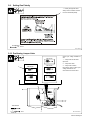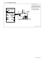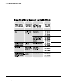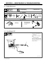
1
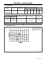
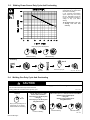
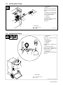
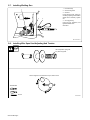
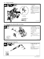
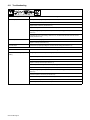
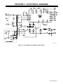
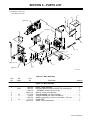
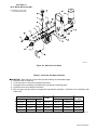
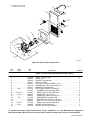
OM-157 066V November 2000 Processes MIG (GMAW) Welding Flux Cored (FCAW) Welding Description Arc Welding Power Source And Wire Feeder R Auto Arc 255 And M-25 Gun For Warranty Claims And Technical Support, Contact: Milweld Inc., National Distributor P.O. Box 338, Hortonville, WI 54944-0338 Tel 920-779-0916 Fax 920-779-0924 TABLE OF CONTENTS WARNING This product, when used for welding or cutting, produces fumes or gases which contain chemicals known to the State of California to cause birth defects and, in some cases, cancer. (California Health & Safety Code Section 25249.5 et seq.) The following terms are used interchangeably throughout this manual: MIG = GMAW OM-154 501V SECTION 1 – SAFETY PRECAUTIONS - READ BEFORE USING . . . . . . . . . . . . . . . . . . . . . . . . . . . . 1-1. Symbol Usage . . . . . . . . . . . . . . . . . . . . . . . . . . . . . . . . . . . . . . . . . . . . . . . . . . . . . . . . . . . . . . . . 1-2. Arc Welding Hazards . . . . . . . . . . . . . . . . . . . . . . . . . . . . . . . . . . . . . . . . . . . . . . . . . . . . . . . . . . 1-3. Additional Symbols For Installation, Operation, And Maintenance . . . . . . . . . . . . . . . . . . . . . 1-4. Principal Safety Standards . . . . . . . . . . . . . . . . . . . . . . . . . . . . . . . . . . . . . . . . . . . . . . . . . . . . . 1-5. EMF Information . . . . . . . . . . . . . . . . . . . . . . . . . . . . . . . . . . . . . . . . . . . . . . . . . . . . . . . . . . . . . . SECTION 2 – INSTALLATION . . . . . . . . . . . . . . . . . . . . . . . . . . . . . . . . . . . . . . . . . . . . . . . . . . . . . . . . . . . 2-1. Specifications . . . . . . . . . . . . . . . . . . . . . . . . . . . . . . . . . . . . . . . . . . . . . . . . . . . . . . . . . . . . . . . . 2-2. Volt-Ampere Curve . . . . . . . . . . . . . . . . . . . . . . . . . . . . . . . . . . . . . . . . . . . . . . . . . . . . . . . . . . . . 2-3. Welding Power Source Duty Cycle And Overheating . . . . . . . . . . . . . . . . . . . . . . . . . . . . . . . . 2-4. Welding Gun Duty Cycle And Overheating . . . . . . . . . . . . . . . . . . . . . . . . . . . . . . . . . . . . . . . . 2-5. Installing Work Clamp . . . . . . . . . . . . . . . . . . . . . . . . . . . . . . . . . . . . . . . . . . . . . . . . . . . . . . . . . . 2-6. Installing Gas Supply . . . . . . . . . . . . . . . . . . . . . . . . . . . . . . . . . . . . . . . . . . . . . . . . . . . . . . . . . . 2-7. Installing Welding Gun . . . . . . . . . . . . . . . . . . . . . . . . . . . . . . . . . . . . . . . . . . . . . . . . . . . . . . . . . 2-8. Installing Wire Spool And Adjusting Hub Tension . . . . . . . . . . . . . . . . . . . . . . . . . . . . . . . . . . . 2-9. Setting Gun Polarity . . . . . . . . . . . . . . . . . . . . . . . . . . . . . . . . . . . . . . . . . . . . . . . . . . . . . . . . . . . 2-10. Positioning Jumper Links . . . . . . . . . . . . . . . . . . . . . . . . . . . . . . . . . . . . . . . . . . . . . . . . . . . . . . . 2-11. Electrical Service Guide . . . . . . . . . . . . . . . . . . . . . . . . . . . . . . . . . . . . . . . . . . . . . . . . . . . . . . . . 2-12. Selecting A Location And Connecting Input Power . . . . . . . . . . . . . . . . . . . . . . . . . . . . . . . . . . 2-13. Threading Welding Wire . . . . . . . . . . . . . . . . . . . . . . . . . . . . . . . . . . . . . . . . . . . . . . . . . . . . . . . . SECTION 3 – OPERATION . . . . . . . . . . . . . . . . . . . . . . . . . . . . . . . . . . . . . . . . . . . . . . . . . . . . . . . . . . . . . 3-1. Front Panel Controls . . . . . . . . . . . . . . . . . . . . . . . . . . . . . . . . . . . . . . . . . . . . . . . . . . . . . . . . . . . 3-2. Center Baffle Controls . . . . . . . . . . . . . . . . . . . . . . . . . . . . . . . . . . . . . . . . . . . . . . . . . . . . . . . . . 3-3. Weld Parameter Chart . . . . . . . . . . . . . . . . . . . . . . . . . . . . . . . . . . . . . . . . . . . . . . . . . . . . . . . . . SECTION 4 – MAINTENANCE & TROUBLESHOOTING . . . . . . . . . . . . . . . . . . . . . . . . . . . . . . . . . . . . 4-1. Routine Maintenance . . . . . . . . . . . . . . . . . . . . . . . . . . . . . . . . . . . . . . . . . . . . . . . . . . . . . . . . . . 4-2. Circuit Breaker CB1 . . . . . . . . . . . . . . . . . . . . . . . . . . . . . . . . . . . . . . . . . . . . . . . . . . . . . . . . . . . 4-3. Fuses F1 And F2 . . . . . . . . . . . . . . . . . . . . . . . . . . . . . . . . . . . . . . . . . . . . . . . . . . . . . . . . . . . . . 4-4. Changing Drive Roll And Wire Inlet Guide . . . . . . . . . . . . . . . . . . . . . . . . . . . . . . . . . . . . . . . . . 4-5. Replacing Gun Contact Tip . . . . . . . . . . . . . . . . . . . . . . . . . . . . . . . . . . . . . . . . . . . . . . . . . . . . . 4-6. Cleaning Or Replacing Gun Liner . . . . . . . . . . . . . . . . . . . . . . . . . . . . . . . . . . . . . . . . . . . . . . . . 4-7. Replacing Switch And/Or Head Tube . . . . . . . . . . . . . . . . . . . . . . . . . . . . . . . . . . . . . . . . . . . . . 4-8. Troubleshooting . . . . . . . . . . . . . . . . . . . . . . . . . . . . . . . . . . . . . . . . . . . . . . . . . . . . . . . . . . . . . . SECTION 5 – ELECTRICAL DIAGRAM . . . . . . . . . . . . . . . . . . . . . . . . . . . . . . . . . . . . . . . . . . . . . . . . . . . SECTION 6 – PARTS LIST . . . . . . . . . . . . . . . . . . . . . . . . . . . . . . . . . . . . . . . . . . . . . . . . . . . . . . . . . . . . . . OPTIONS AND ACCESSORIES WARRANTY 1 1 1 3 3 4 5 5 5 6 6 7 7 8 8 9 9 10 10 11 12 12 13 14 16 16 16 17 17 17 18 19 20 21 23 SECTION 1 – SAFETY PRECAUTIONS - READ BEFORE USING som _nd_4/98 1-1. Symbol Usage Means Warning! Watch Out! There are possible hazards with this procedure! The possible hazards are shown in the adjoining symbols. Y Marks a special safety message. . Means “Note”; not safety related. This group of symbols means Warning! Watch Out! possible ELECTRIC SHOCK, MOVING PARTS, and HOT PARTS hazards. Consult symbols and related instructions below for necessary actions to avoid the hazards. 1-2. Arc Welding Hazards Y The symbols shown below are used throughout this manual to call attention to and identify possible hazards. When you see the symbol, watch out, and follow the related instructions to avoid the hazard. The safety information given below is only a summary of the more complete safety information found in the Safety Standards listed in Section 1-4. Read and follow all Safety Standards. D If earth grounding of the workpiece is required, ground it directly with a separate cable. Y Only qualified persons should install, operate, maintain, and repair this unit. D Wear a safety harness if working above floor level. D Keep all panels and covers securely in place. Y During operation, keep everybody, especially children, away. D Clamp work cable with good metal-to-metal contact to workpiece or worktable as near the weld as practical. ELECTRIC SHOCK can kill. Touching live electrical parts can cause fatal shocks or severe burns. The electrode and work circuit is electrically live whenever the output is on. The input power circuit and machine internal circuits are also live when power is on. In semiautomatic or automatic wire welding, the wire, wire reel, drive roll housing, and all metal parts touching the welding wire are electrically live. Incorrectly installed or improperly grounded equipment is a hazard. D Do not touch electrode if you are in contact with the work, ground, or another electrode from a different machine. D Use only well-maintained equipment. Repair or replace damaged parts at once. Maintain unit according to manual. D Insulate work clamp when not connected to workpiece to prevent contact with any metal object. D Do not connect more than one electrode or work cable to any single weld output terminal. SIGNIFICANT DC VOLTAGE exists after removal of input power on inverters. D Turn Off inverter, disconnect input power, and discharge input capacitors according to instructions in Maintenance Section before touching any parts. D Do not touch live electrical parts. D Wear dry, hole-free insulating gloves and body protection. D Insulate yourself from work and ground using dry insulating mats or covers big enough to prevent any physical contact with the work or ground. D Do not use AC output in damp areas, if movement is confined, or if there is a danger of falling. D Use AC output ONLY if required for the welding process. D If AC output is required, use remote output control if present on unit. D Disconnect input power or stop engine before installing or servicing this equipment. Lockout/tagout input power according to OSHA 29 CFR 1910.147 (see Safety Standards). D Properly install and ground this equipment according to its Owner’s Manual and national, state, and local codes. D Keep your head out of the fumes. Do not breathe the fumes. D Always verify the supply ground – check and be sure that input power cord ground wire is properly connected to ground terminal in disconnect box or that cord plug is connected to a properly grounded receptacle outlet. D When making input connections, attach proper grounding conductor first – double-check connections. D Frequently inspect input power cord for damage or bare wiring – replace cord immediately if damaged – bare wiring can kill. D Turn off all equipment when not in use. D Do not use worn, damaged, undersized, or poorly spliced cables. D Do not weld in locations near degreasing, cleaning, or spraying operations. The heat and rays of the arc can react with vapors to form highly toxic and irritating gases. D Do not drape cables over your body. FUMES AND GASES can be hazardous. Welding produces fumes and gases. Breathing these fumes and gases can be hazardous to your health. D If inside, ventilate the area and/or use exhaust at the arc to remove welding fumes and gases. D If ventilation is poor, use an approved air-supplied respirator. D Read the Material Safety Data Sheets (MSDSs) and the manufacturer’s instructions for metals, consumables, coatings, cleaners, and degreasers. D Work in a confined space only if it is well ventilated, or while wearing an air-supplied respirator. Always have a trained watchperson nearby. Welding fumes and gases can displace air and lower the oxygen level causing injury or death. Be sure the breathing air is safe. D Do not weld on coated metals, such as galvanized, lead, or cadmium plated steel, unless the coating is removed from the weld area, the area is well ventilated, and if necessary, while wearing an air-supplied respirator. The coatings and any metals containing these elements can give off toxic fumes if welded. OM-157 066 Page 1 ARC RAYS can burn eyes and skin. Arc rays from the welding process produce intense visible and invisible (ultraviolet and infrared) rays that can burn eyes and skin. Sparks fly off from the weld. D Wear a welding helmet fitted with a proper shade of filter to protect your face and eyes when welding or watching (see ANSI Z49.1 and Z87.1 listed in Safety Standards). D Wear approved safety glasses with side shields under your helmet. D Use protective screens or barriers to protect others from flash and glare; warn others not to watch the arc. D Wear protective clothing made from durable, flame-resistant material (leather and wool) and foot protection. BUILDUP OF GAS can injure or kill. D Shut off shielding gas supply when not in use. D Always ventilate confined spaces or use approved air-supplied respirator. HOT PARTS can cause severe burns. D Do not touch hot parts bare handed. D Allow cooling period before working on gun or torch. MAGNETIC FIELDS can affect pacemakers. WELDING can cause fire or explosion. Welding on closed containers, such as tanks, drums, or pipes, can cause them to blow up. Sparks can fly off from the welding arc. The flying sparks, hot workpiece, and hot equipment can cause fires and burns. Accidental contact of electrode to metal objects can cause sparks, explosion, overheating, or fire. Check and be sure the area is safe before doing any welding. D Protect yourself and others from flying sparks and hot metal. D Do not weld where flying sparks can strike flammable material. D Remove all flammables within 35 ft (10.7 m) of the welding arc. If this is not possible, tightly cover them with approved covers. D Be alert that welding sparks and hot materials from welding can easily go through small cracks and openings to adjacent areas. D Watch for fire, and keep a fire extinguisher nearby. D Be aware that welding on a ceiling, floor, bulkhead, or partition can cause fire on the hidden side. D Do not weld on closed containers such as tanks, drums, or pipes, unless they are properly prepared according to AWS F4.1 (see Safety Standards). D Connect work cable to the work as close to the welding area as practical to prevent welding current from traveling long, possibly unknown paths and causing electric shock and fire hazards. D Do not use welder to thaw frozen pipes. D Remove stick electrode from holder or cut off welding wire at contact tip when not in use. D Wear oil-free protective garments such as leather gloves, heavy shirt, cuffless trousers, high shoes, and a cap. D Remove any combustibles, such as a butane lighter or matches, from your person before doing any welding. FLYING METAL can injure eyes. D Welding, chipping, wire brushing, and grinding cause sparks and flying metal. As welds cool, they can throw off slag. D Wear approved safety glasses with side shields even under your welding helmet. OM-157 066 Page 2 D Pacemaker wearers keep away. D Wearers should consult their doctor before going near arc welding, gouging, or spot welding operations. NOISE can damage hearing. Noise from some processes or equipment can damage hearing. D Wear approved ear protection if noise level is high. CYLINDERS can explode if damaged. Shielding gas cylinders contain gas under high pressure. If damaged, a cylinder can explode. Since gas cylinders are normally part of the welding process, be sure to treat them carefully. D Protect compressed gas cylinders from excessive heat, mechanical shocks, slag, open flames, sparks, and arcs. D Install cylinders in an upright position by securing to a stationary support or cylinder rack to prevent falling or tipping. D Keep cylinders away from any welding or other electrical circuits. D Never drape a welding torch over a gas cylinder. D Never allow a welding electrode to touch any cylinder. D Never weld on a pressurized cylinder – explosion will result. D Use only correct shielding gas cylinders, regulators, hoses, and fittings designed for the specific application; maintain them and associated parts in good condition. D Turn face away from valve outlet when opening cylinder valve. D Keep protective cap in place over valve except when cylinder is in use or connected for use. D Read and follow instructions on compressed gas cylinders, associated equipment, and CGA publication P-1 listed in Safety Standards. 1-3. Additional Symbols For Installation, Operation, And Maintenance FIRE OR EXPLOSION hazard. MOVING PARTS can cause injury. D Do not install or place unit on, over, or near combustible surfaces. D Do not install unit near flammables. D Do not overload building wiring – be sure power supply system is properly sized, rated, and protected to handle this unit. D Keep away from moving parts such as fans. D Keep all doors, panels, covers, and guards closed and securely in place. FALLING UNIT can cause injury. D Use lifting eye to lift unit only, NOT running gear, gas cylinders, or any other accessories. D Use equipment of adequate capacity to lift and support unit. D If using lift forks to move unit, be sure forks are long enough to extend beyond opposite side of unit. OVERUSE can cause OVERHEATING D Allow cooling period; follow rated duty cycle. D Reduce current or reduce duty cycle before starting to weld again. D Do not block or filter airflow to unit. H.F. RADIATION can cause interference. D High-frequency (H.F.) can interfere with radio navigation, safety services, computers, and communications equipment. D Have only qualified persons familiar with electronic equipment perform this installation. D The user is responsible for having a qualified electrician promptly correct any interference problem resulting from the installation. D If notified by the FCC about interference, stop using the equipment at once. D Have the installation regularly checked and maintained. D Keep high-frequency source doors and panels tightly shut, keep spark gaps at correct setting, and use grounding and shielding to minimize the possibility of interference. STATIC (ESD) can damage PC boards. D Put on grounded wrist strap BEFORE handling boards or parts. D Use proper static-proof bags and boxes to store, move, or ship PC boards. ARC WELDING can cause interference. MOVING PARTS can cause injury. D Keep away from moving parts. D Keep away from pinch points such as drive rolls. D D WELDING WIRE can cause injury. D Do not press gun trigger until instructed to do so. D Do not point gun toward any part of the body, other people, or any metal when threading welding wire. D D D Electromagnetic energy can interfere with sensitive electronic equipment such as computers and computer-driven equipment such as robots. D Be sure all equipment in the welding area is electromagnetically compatible. To reduce possible interference, keep weld cables as short as possible, close together, and down low, such as on the floor. Locate welding operation 100 meters from any sensitive electronic equipment. Be sure this welding machine is installed and grounded according to this manual. If interference still occurs, the user must take extra measures such as moving the welding machine, using shielded cables, using line filters, or shielding the work area. 1-4. Principal Safety Standards Safety in Welding and Cutting, ANSI Standard Z49.1, from American Welding Society, 550 N.W. LeJeune Rd, Miami FL 33126 Safety and Health Standards, OSHA 29 CFR 1910, from Superintendent of Documents, U.S. Government Printing Office, Washington, D.C. 20402. Recommended Safe Practices for the Preparation for Welding and Cutting of Containers That Have Held Hazardous Substances, American Welding Society Standard AWS F4.1, from American Welding Society, 550 N.W. LeJeune Rd, Miami, FL 33126 National Electrical Code, NFPA Standard 70, from National Fire Protection Association, Batterymarch Park, Quincy, MA 02269. Safe Handling of Compressed Gases in Cylinders, CGA Pamphlet P-1, from Compressed Gas Association, 1235 Jefferson Davis Highway, Suite 501, Arlington, VA 22202. Code for Safety in Welding and Cutting, CSA Standard W117.2, from Canadian Standards Association, Standards Sales, 178 Rexdale Boulevard, Rexdale, Ontario, Canada M9W 1R3. Safe Practices For Occupation And Educational Eye And Face Protection, ANSI Standard Z87.1, from American National Standards Institute, 1430 Broadway, New York, NY 10018. Cutting And Welding Processes, NFPA Standard 51B, from National Fire Protection Association, Batterymarch Park, Quincy, MA 02269. OM-157 066 Page 3 1-5. EMF Information Considerations About Welding And The Effects Of Low Frequency Electric And Magnetic Fields Welding current, as it flows through welding cables, will cause electromagnetic fields. There has been and still is some concern about such fields. However, after examining more than 500 studies spanning 17 years of research, a special blue ribbon committee of the National Research Council concluded that: “The body of evidence, in the committee’s judgment, has not demonstrated that exposure to powerfrequency electric and magnetic fields is a human-health hazard.” However, studies are still going forth and evidence continues to be examined. Until the final conclusions of the research are reached, you may wish to minimize your exposure to electromagnetic fields when welding or cutting. To reduce magnetic fields in the workplace, use the following procedures: OM-157 066 Page 4 1. Keep cables close together by twisting or taping them. 2. Arrange cables to one side and away from the operator. 3. Do not coil or drape cables around your body. 4. Keep welding power source and cables as far away from operator as practical. 5. Connect work clamp to workpiece as close to the weld as possible. About Pacemakers: Pacemaker wearers consult your doctor first. If cleared by your doctor, then following the above procedures is recommended. SECTION 2 – INSTALLATION 2-1. Specifications Rated Welding Output Amperage Range DC Maximum OpenCircuit Voltage DC 40 – 250 42 200 A @ 28 Volts DC, 60% Duty Cycle 250 A @ 28 Volts DC, 40% Duty Cycle Amperes Input at Rated Load Output, 50 or 60 Hz, Single-Phase 200 V 230 V 460 V 575 V KVA KW 46 1.1* 40 1.3* 20 0.5* 16 0.4* 9.5 0.31* 8.3 0.18* Wire Type And Diameter Solid Steel / Stainless Steel Flux Cored/ Aluminum .023 – .045 in (0.6 – 1.2 mm) .030 – .035 in (0.8 – 0.9 mm) And 3/64 in (1.2 mm) Alu Wire Feed Speed Range Overall Dimensions Weight Length: 37 in (940 mm) 90 – 1030 IPM (2.9 – 26.2 m/min) Width: 19 in (483 mm) 225 lb (102 kg) Height: 32 in (889 mm) *While idling Operating Temperature Range – –20C to +40C Storage Temperature Range – -30C to + 50C 2-2. Volt-Ampere Curve The volt-ampere curves show the minimum and maximum voltage and amperage output capabilities of the welding power source. Curves of other settings fall between the curves shown. ssb1.1 10/91 – SB-049 424-C OM-157 066 Page 5 2-3. Welding Power Source Duty Cycle And Overheating Duty Cycle is percentage of 10 minutes that unit can weld at rated load without overheating. If unit overheats, thermostat(s) opens, output stops, and cooling fan runs. Wait fifteen minutes for unit to cool. Reduce amperage or voltage, or duty cycle before welding. Y Exceeding duty cycle can damage unit and void warranty. 60% Duty Cycle At 200 Amperes 6 Minutes Welding 4 Minutes Resting Overheating A or V 0 15 OR Reduce Duty Cycle Minutes duty1 4/95 – SB-150 215 2-4. Welding Gun Duty Cycle And Overheating CAUTION WELDING LONGER THAN RATED DUTY CYCLE can damage gun and void warranty. • • Do not weld at rated load longer than shown below. Using gasless flux cored wire reduces gun duty cycle. Definition .023 To .045 in (0.6 To 1.1 mm) Hard Or Flux Cored Wires 0 10 Minutes 100% Duty Cycle At 200 Amperes Using CO2 100% Duty Cycle At 150 Amperes Using Mixed Gases warn7.1 8/93 .023 To .045 in (0.6 To 1.1 mm) Hard Or Flux Cored Wires 60% Duty Cycle At 300 Amperes Using CO2 60% Duty Cycle At 200 Amperes Using Mixed Gases Duty Cycle is percentage of 10 minutes that gun can weld at rated load without overheating. Continuous Welding 6 Minutes Welding 4 Minutes Resting SB1.1 8/93 OM-157 066 Page 6 2-5. Installing Work Clamp 1 2 Slide boot onto work cable. Route cable out front panel opening from inside. 4 3 Negative (–) Output Terminal Connect cable to terminal and cover connection with boot. 5 2 Work Cable Boot 4 5 Hardware Work Clamp Route cable through clamp handle and secure as shown. 1 Close door. Tools Needed: 3 1/2, 3/4 in ST-800 918-C 2-6. Installing Gas Supply 1 2 Cylinder Rack Chain Obtain gas cylinder and chain cylinder to rack. 3 4 5 Gas Hose Fitting CO2 Washer Regulator Install washer and regulator onto cylinder. 6 Gas Hose Connection Obtain gas hose with fittings and install between regulator and welding power source. 7 7 Flow Adjust Typical flow rate is 20 cfh (cubic feet per hour). 6 5 4 1 2 3 Tools Needed: 5/8, 1-1/8 in ST-154 623-A / Ref. ST-109 492 OM-157 066 Page 7 2-7. Installing Welding Gun 1 2 3 1 2 Drive Assembly Gun Securing Knob Gun End Loosen securing knob. Insert gun end through opening until it bottoms against drive assembly. Tighten nut. 4 4 Gun Trigger Plug Insert plug into receptacle, and tighten threaded collar. Close door. 3 Ref. ST-800 921-C 2-8. Installing Wire Spool And Adjusting Hub Tension Use compression spring with 8 in (200 mm) spools. When a slight force is needed to turn spool, tension is set. Tools Needed: 15/16 in OM-157 066 Page 8 ST-072573-B 2-9. Setting Gun Polarity 1 1 Polarity Changeover Label Always read and follow manufacture’s recommended polarity. Tools Needed: 3/4, 11/16 in Ref. 190 821-A 2-10. Positioning Jumper Links 230 VOLTS Check input voltage available at site. 1 Jumper Links Access Door Open door. 460 VOLTS 200 VOLTS 2 2 3 Jumper Link Label Jumper Links Location Move jumper links to match input voltage, and label on unit. Close and secure access door. 575 VOLTS 230 VOLTS S-156 140 S-153 980 1 Tools Needed: 3/8 in 3 Ref. ST-800 922-C OM-157 066 Page 9 2-11. Electrical Service Guide Input Voltage 200 230 460 575 Input Amperes At Rated Output 46 40 20 16 Circuit Breaker 1, Time-Delay Fuse 2 50 50 25 20 Fuse 3 70 60 30 25 10 10 14 14 59 (18) 77 (24) 122 (37) 190 (58) 10 10 14 14 Max Recommended Standard Fuse Or Circuit Breaker Rating In Amperes Normal Operating Min Input Conductor Size In AWG/Kcmil Max Recommended Input Conductor Length In Feet (Meters) Min Grounding Conductor Size In AWG/Kcmil Reference: 1999 National Electrical Code (NEC) 1 Choose a circuit breaker with time-current curves comparable to a Time Delay Fuse. 2 “Time-Delay” fuses are UL class “RK5” . 3 “Normal Operating” (general purpose – no intentional delay) fuses are UL class “K5” (up to and including 60 amp), and UL class “H” ( 65 amp and above). Y Caution: Failure to follow these fuse and circuit breaker recommendations could create an electric shock or fire hazard. 2-12. Selecting A Location And Connecting Input Power 1 Rating Label Supply correct input power. 2 3 Plug Receptacle Connect plug to receptacle. 4 18 in (457 mm) of space for airflow Y Do not move or operate unit where it could tip. Y Always connect grounding conductor first. = GND/PE Line Disconnect Device See Section 2-11. Y Special installation may be required where gasoline or volatile liquids are present – see NEC Article 511 or CEC Section 20. 4 L1 L2 2 1 3 L2 L1 230 VAC, 1 ST-800 923-A OM-157 066 Page 10 2-13. Threading Welding Wire 4 1 Wire Spool 2 Welding Wire 3 Inlet Wire Guide 4 Pressure Adjustment Knob 5 Drive Roll 6 Outlet Wire Guide 7 Gun Conduit Cable Lay gun cable out straight. 7 Tools Needed: 1 2 3 6 5 4 in (102 mm) 6 in (150 mm) Open pressure assembly. Pull and hold wire; cut off end. . Use pressure indicator Tighten scale to set a desired drive roll pressure. Pressure Indicator Scale 1 2 3 4 Close and tighten pressure assembly, and let go of wire. Push wire thru guides into gun; continue to hold wire. Remove gun nozzle and contact tip. Turn On. Tighten WOOD Press gun trigger until wire comes out of gun. Reinstall contact tip and nozzle. Feed wire to check drive roll pressure. Tighten knob enough to prevent slipping. 1 2 3 4 Cut off wire. Close and latch door. Ref. ST-148 261-D / ST-159 218-C / ST-801 083 / S-0627-A OM-157 066 Page 11 SECTION 3 – OPERATION 3-1. Front Panel Controls Controls For Standard Units 1 Wire Speed Control The scale around the control is percent, not wire feed speed. 1 2 2 Voltage Switch Use control and Voltage Range Selector (see Section 3-2) to set arc voltage. Step 6 of Low range and Step 1 of High range overlap. 3 4 Pilot Light Power Switch 3 4 Ref. ST-171 639-C / Ref. ST-174 843-A OM-157 066 Page 12 3-2. Center Baffle Controls 1 Wire Mode Switch For better control of wire speed use the Low position when wire speed is between 90 and 670 ipm. Use the Full position when wire speed is between 150 ipm and 1030 ipm. 1 PRESS TO RESET CB1 2 2 Voltage Range Selector Place switch in desired position. DO NOT SWITCH UNDER LOAD WIRE MODE FULL LOW VOLTAGE RANGE HIGH LOW Ref. ST-800 919-B / S-171 601 OM-157 066 Page 13 3-3. Weld Parameter Chart OM-157 066 Page 14 Ref. 200 062 OM-157 066 Page 15 SECTION 4 – MAINTENANCE & TROUBLESHOOTING 4-1. Routine Maintenance . Maintain more often Y Disconnect power before maintaining. during severe conditions. 3 Months Clean And Tighten Weld Terminals Repair Or Replace Cracked Cables And Cords Replace Damaged Or Unreadable Labels 6 Months Remove drive roll and carrier. Apply light coat of oil or grease to drive motor shaft. Blow Out Or Vacuum Inside 4-2. Circuit Breaker CB1 1 Circuit Breaker CB1 If CB1 opens, wire feeding stops. 2 Welding Gun Check gun liner for blockage or kinks. 3 Wire Drive Assembly Check for jammed wire, binding drive gear or misaligned drive rolls. 1 Allow cooling period and reset breaker. Close door. 2 3 Ref. ST-800 924-C OM-157 066 Page 16 4-3. Fuses F1 And F2 Y Turn Off unit, and disconnect input power. 1 Fuse F1 (See Parts List For Rating) F1 protects the 115 volts ac winding of transformer T1. If F1 opens, all weld output stops and pilot light PL1 goes out. 2 2 Fuse F2 (See Parts List For Rating) F2 protects the 24 volts ac winding of transformer T1. If F2 opens, all weld output stops. 1 Tools Needed: 3/8 in Ref. ST-800 928-B 4-4. Changing Drive Roll And Wire Inlet Guide 1 2 5 3 Securing Screw Inlet Wire Guide Loosen screw. Slide tip as close to drive rolls as possible without touching. Tighten screw. 2 3 Anti-Wear Guide Install guide as shown. 4 Drive Roll Install correct drive roll for wire size and type. 5 1 Tools Needed: 5/64 in Drive Roll Securing Nut Turn nut one click to secure drive roll. 4 7/16 in ST-150 227-D 4-5. Replacing Gun Contact Tip Y Turn Off unit before replacing contact tip. 1 2 Nozzle Contact Tip Cut off welding wire at contact tip. Remove nozzle. 2 1 Remove contact tip and install new contact tip. Reinstall nozzle. Tools Needed: Ref. 800 797-C OM-157 066 Page 17 4-6. Cleaning Or Replacing Gun Liner Tools Needed: Y Disconnect gun first. 3/8 in Head tube Remove nozzle, contact tip, adapter, and wire outlet guide. 3/8 in Remove liner. Lay gun cable out straight before installing new liner. To Reassemble Gun: Insert new liner. Install and tighten wire outlet guide. Blow out gun casing. Cut liner off 3/4 in (20 mm) (3/8 in [9.5 mm] for aluminum) from head tube. Install adapter, contact tip, and nozzle. Ref. ST-800 797-C OM-157 066 Page 18 4-7. Replacing Switch And/Or Head Tube Y Disconnect gun first. 1 Remove handle locking nut. 3 2 4 Slide handle. Remove switch housing. Note: If installing new switch, push switch lead connectors onto terminal of new switch (polarity is not important). Install switch back into handle, and secure with handle locking nut. If replacing head tube, continue to end of figure. Secure head tube in vice. 5 6 Loosen jam nut. Remove from vice and turn head tube out by hand. Install existing shock washer onto new head tube. Hand-tighten head tube into connector cable. 8 7 Place head tube in vice and tighten until nuts are tight. Remove from vice. Reposition handle and install switch housing. Secure with handle locking nut. Tools Needed: 3/4 in Ref. ST-800 795-C OM-157 066 Page 19 4-8. Troubleshooting Welding Trouble No weld output; wire does not feed. Remedy Secure power cord plug in receptacle (see Section 2-12). Reset circuit breaker CB1 (see Section 4-2). Replace fuse F1 and/or F2 (see Section 4-3). Replace building line fuse or reset circuit breaker if open (see Section 2-12). Secure gun trigger plug in receptacle or repair leads, or replace trigger switch (see Section 2-7 and/or 4-7). Thermostat TP1 open (overheating). Allow fan to run; the thermostat will close when the unit has cooled (see Section 2-3). No weld output; wire feeds. Connect work clamp to get good metal to metal contact. Replace contact tip (see Section 4-5). Low weld output. Connect unit to proper input voltage or check for low line voltage (see Section 2-12). Wire Drive/Gun Trouble Remedy Electrode wire feeding stops during Straighten gun cable and/or replace damaged parts (see Section 4-6). welding. Adjust drive roll pressure (see Section 2-13). Readjust hub tension (see Section 2-8). Replace contact tip if blocked (see Section 4-5). Clean or replace wire inlet guide or liner if dirty or plugged (see Section 4-6). Replace drive rolls if worn or slipping (see Section 4-4). Secure gun trigger plug in receptacle or repair leads, or replace trigger switch (see Section 2-7 and/or 4-7). Check and replace F1 and/or F2 (see Section 4-3). Check and clear any restrictions at drive assembly and liner (see Section 4-6). Have nearest Factory Authorized Service Agent check drive motor. Check relay CR1, and replace if necessary. OM-157 066 Page 20 SECTION 5 – ELECTRICAL DIAGRAM SB-173 544-E Figure 5-1. Circuit Diagram For Welding Power Source OM-157 066 Page 21 Notes OM-157 066 Page 22 SECTION 6 – PARTS LIST . Hardware is common and not available unless listed. 11 10 8 9 Figure 6-2 – 2 Figure 6-4 – 7 1 3 6 5 12 13 14 15 16 Figure 6-6 - 20 17 18 Figure 6-5 – 19 ST-800 930-D Figure 6-1. Main Assembly Item No. Dia. Mkgs. Part No. Description Quantity Figure 6-1. Main Assembly . . . 1 . . . . . . . . . . . . . . . . . . . 146 168 . . . . . . . . . . . PLG7 . . . . . . . 083 526 . . . . . . . . . . . . . . . . . . . . . . . . . 009 418 . . . 2 . . . . . . . . . . . . . . . . . Figure 6-2 . . . 3 . . . . . . . T1 . . . . . . . . . 171 658 . . . 3 . . . . . . . T1 . . . . . . . . . 172 520 . . . 5 . . . . . . . . . . . . . . . . . . . 186 758 . . . 6 . . . . . . . Z1 . . . . . . . . . 171 213 . . . 7 . . . . . . . . . . . . . . . . . Figure 6-4 . . PANEL, center enclosure . . . . . . . . . . . . . . . . . . . . . . . . . . . . . . . . . . . 1 . . HOUSING RECEPTACLE & SOCKETS, (consisting of) . . . . . . . . . 1 . . . . TERMINAL, female 1skt 20-14 wire . . . . . . . . . . . . . . . . . . . . . . . 12 . . BAFFLE, center w/components . . . . . . . . . . . . . . . . . . . . . . . . . . . . . . 1 . . TRANSFORMER, pwr main (200/230) . . . . . . . . . . . . . . . . . . . . . . . . 1 . . TRANSFORMER, pwr main (230/460/575) . . . . . . . . . . . . . . . . . . . . 1 . . WHEEL, polyprolene 10 in dia x 2.250 wide x .750 bore . . . . . . . . . 2 . . STABILIZER . . . . . . . . . . . . . . . . . . . . . . . . . . . . . . . . . . . . . . . . . . . . . . 1 . . PANEL, rear w/components . . . . . . . . . . . . . . . . . . . . . . . . . . . . . . . . . 1 OM-157 066 Page 23 Item No. Dia. Mkgs. Part No. Description Quantity Figure 6-1. Main Assembly . . . 8 . . . . . . . . . . . . . . . . . . . 146 165 . . PANEL, side LH . . . . . . . . . . . . . . . . . . . . . . . . . . . . . . . . . . . . . . . . . . . 1 . . . 9 . . . . . . . . . . . . . . . . . . . 089 899 . . LATCH, slide flush mtg hole . . . . . . . . . . . . . . . . . . . . . . . . . . . . . . . . . 2 . . . 10 . . . . . . . . . . . . . . . . . . . 146 167 . . PANEL, side . . . . . . . . . . . . . . . . . . . . . . . . . . . . . . . . . . . . . . . . . . . . . . 1 . . . 11 . . . . . . . . . . . . . . . . . . . 134 464 . . LABEL, warning general precautionary . . . . . . . . . . . . . . . . . . . . . . . 1 . . . 12 . . . . . . . . . . . . . . . . . . +170 513 . . WRAPPER . . . . . . . . . . . . . . . . . . . . . . . . . . . . . . . . . . . . . . . . . . . . . . . 1 . . . . . . . . . . . . . . . . . . . . . . . . . 117 860 . . BLANK, snap-in nyl .187mtg hole . . . . . . . . . . . . . . . . . . . . . . . . . . . . 2 . . . 13 . . . . . . . . . . . . . . . . . . . 188 911 . . CORD SET, pwr 250V 8-10ga 3/c 12ft . . . . . . . . . . . . . . . . . . . . . . . . 1 . . . 13 . . . . . . . . . . . . . . . . . . . 187 255 . . CORD SET, pwr 250V 8-10ga 3/c 12ft (230/460/575) . . . . . . . . . . . 1 . . . 14 . . . . . . . . . . . . . . . . . . . 146 161 . . BASE . . . . . . . . . . . . . . . . . . . . . . . . . . . . . . . . . . . . . . . . . . . . . . . . . . . . 1 . . . 15 . . . . . . . . . . . . . . . . . . . 052 692 . . AXLE, running gear (consisting of) . . . . . . . . . . . . . . . . . . . . . . . . . . . 1 . . . 16 . . . . . . . . . . . . . . . . . . . 121 614 . . . . RING, retaining ext .750 shaft x .085grv depth . . . . . . . . . . . . . . . 2 . . . 17 . . . . . . R1 . . . . . . . . 091 685 . . RESISTOR, WW fxd 50W 25 ohm . . . . . . . . . . . . . . . . . . . . . . . . . . . 1 . . . 18 . . . . . . . . . . . . . . . . . . . 008 999 . . CASTER, plstc swvl 4 in dia . . . . . . . . . . . . . . . . . . . . . . . . . . . . . . . . . 2 . . . 19 . . . . . . . . . . . . . . . . . Figure 6-5 . . PANEL, front w/components . . . . . . . . . . . . . . . . . . . . . . . . . . . . . . . . 1 . . . 20 . . . . . . . . . . . . . . . . . . . 169 596 . . GUN, 12 ft .030-.035 wire (Fig 6-4) . . . . . . . . . . . . . . . . . . . . . . . . . . . 1 . . . . . . . . . . . . . . . . . . . . . . . . . 192 121 . . REGULATOR/FLOWMETER, 10-50 CFH . . . . . . . . . . . . . . . . . . . . . 1 . . . . . . . . . . . . . . . . . . . . . . . . . 144 108 . . HOSE, gas 5ft . . . . . . . . . . . . . . . . . . . . . . . . . . . . . . . . . . . . . . . . . . . . 1 . . . . . . . . . . . . . . . . . . . . . . . . . 130 750 . . CLAMP, ground 350A . . . . . . . . . . . . . . . . . . . . . . . . . . . . . . . . . . . . . . 1 . . . . . . . . . . . . . . . . . . . . . . . . . 600 318 . . CABLE, weld cop strd No. 3 (order by ft) . . . . . . . . . . . . . . . . . . . . 10ft +When ordering a component originally displaying a precautionary label, the label should also be ordered. To maintain the factory original performance of your equipment, use only Manufacturer’s Suggested Replacement Parts. Model and serial number required when ordering parts from your local distributor. OM-157 066 Page 24 1 2 3 4 5 11 6 10 7 31 12 13 8 9 14 30 29 15 16 20 21 17 18 28 (Fig. 6–3) 19 22 27 23 26 25 24 . Hardware is common and not available unless listed. ST-800 931-D Figure 6-2. Baffle, Center w/Components OM-157 066 Page 25 Item No. Dia. Mkgs. Part No. Description Quantity Figure 6-2. Baffle, Center w/Components (Fig 6-1 Item 2) . . 1 . . . . . . . . . . . . 058 427 . . 2 . . . . . . . . . . . . 085 980 . . 3 . . . . . . . . . . . . 605 941 . . 4 . . . . . . . . . . . . 186 437 . . 5 . . . . . . . . . . . . 057 971 . . 6 . . . . . . . . . . . . 057 745 . . 7 . . . . . . . . . . . . 186 435 . . 8 . . . . . . . . . . . . 186 436 . . 9 . . . . . . . . . . . . 177 307 . . 10 . . . . . . . . . . . 174 812 . . . . . . . . . . . . . . . . . 186 998 . . 11 . . . . . . . . . . . 083 147 . . 12 . . . . . . . . . . . 082 902 . . 13 . . . . . . . . . . . 185 643 . . 14 . . . . C5 . . . 184 584 . . . . . . . . . . . . . . . . . 185 642 . . 15 . . . . W . . . . 195 568 . . . . . . . . . . . . . . . . . 114 786 . . 16 . . . . . . . . . . . 134 201 . . 17 . . . PC1 . . . 173 002 . . . . . . . . . CR1 . . . *080 388 . . 18 . . . . F2 . . . *012 658 . . 19 . . . . F1 . . . *073 426 . . . . . . . . PLG3 . . 165 896 . . . . . . . . PLG4 . . 135 558 . . . . . . . . PLG5 . . 165 745 . . 20 . . . CB1 . . . 083 431 . . 21 . . . . S3 . . . 011 609 . . 22 . . . . S4 . . . 171 610 . . . . . . . . . . . . . . . . . 186 058 . . 23 . . . TE1 . . . 189 910 . . 23 . . . TE1 . . . 195 551 . . 24 . . . . . . . . . . . 038 618 . . 25 . . . POS . . 039 047 . . 26 . . . NEG . . 039 046 . . . . . . . . . C6,7 . . 128 750 . . 27 . . . . . . . . . . . 071 971 . . 28 . . . . . . . . . . . . Fig 6-3 . . 29 . . . . . . . . . . . 148 956 . . 30 . . . . . . . . . . +188 917 . . 31 . . . . . . . . . . . 021 469 . . RING, retaining spool . . . . . . . . . . . . . . . . . . . . . . . . . . . . . . . . . . . . . . . . . . . . . . 1 . . NUT, stl hex full .625-11 . . . . . . . . . . . . . . . . . . . . . . . . . . . . . . . . . . . . . . . . . . . . 1 . . WASHER, flat stl .640 ID x 1.000 OD x 14ga thk . . . . . . . . . . . . . . . . . . . . . . . 1 . . SPRING, cprsn .845 OD x .110 wire x 1.500 . . . . . . . . . . . . . . . . . . . . . . . . . . 1 . . WASHER, flat stl keyed 1.500dia x .125thk . . . . . . . . . . . . . . . . . . . . . . . . . . . 1 . . SPRING, cprsn 2.430 OD x .090 wire x 2.500 . . . . . . . . . . . . . . . . . . . . . . . . . 1 . . HUB, spool . . . . . . . . . . . . . . . . . . . . . . . . . . . . . . . . . . . . . . . . . . . . . . . . . . . . . . . 1 . . WASHER, brake plastic . . . . . . . . . . . . . . . . . . . . . . . . . . . . . . . . . . . . . . . . . . . . 2 . . REEL, support . . . . . . . . . . . . . . . . . . . . . . . . . . . . . . . . . . . . . . . . . . . . . . . . . . . . 1 . . BAFFLE, center . . . . . . . . . . . . . . . . . . . . . . . . . . . . . . . . . . . . . . . . . . . . . . . . . . . 1 . . KIT, capacitor bank (consisting of) . . . . . . . . . . . . . . . . . . . . . . . . . . . . . . . . . . . 1 . . . . GROMMET, scr No. 8/10 panel hole .312sq .500 high . . . . . . . . . . . . . . . . 6 . . . . STRIP, mtg center capacitor . . . . . . . . . . . . . . . . . . . . . . . . . . . . . . . . . . . . . . 1 . . . . STRIP, mtg capacitor . . . . . . . . . . . . . . . . . . . . . . . . . . . . . . . . . . . . . . . . . . . . . 2 . . . . CAPACITOR, elctlt 15000uf 45VDC . . . . . . . . . . . . . . . . . . . . . . . . . . . . . . . . 8 . . . . INSULATOR, capacitor . . . . . . . . . . . . . . . . . . . . . . . . . . . . . . . . . . . . . . . . . . . 2 . . CONTACTOR w/LINKS, def prp 60A 3P (consisting of) . . . . . . . . . . . . . . . . . 1 . . . . LINK, connecting contactor terminal . . . . . . . . . . . . . . . . . . . . . . . . . . . . . . . . 2 . . STAND-OFF SUPPORT, PC card .312/.375 w/post & lock . . . . . . . . . . . . . . 4 . . CIRCUIT CARD, motor speed control (consisting of) . . . . . . . . . . . . . . . . . . . 1 . . . . RELAY, encl 24 VAC 3PDT . . . . . . . . . . . . . . . . . . . . . . . . . . . . . . . . . . . . . . . 1 . . . . FUSE, mintr gl slo-blo 2A 125V . . . . . . . . . . . . . . . . . . . . . . . . . . . . . . . . . . . . 1 . . . . FUSE, mintr gl slo-blo 5A 125V . . . . . . . . . . . . . . . . . . . . . . . . . . . . . . . . . . . . 1 . . CONNECTOR & SOCKETS . . . . . . . . . . . . . . . . . . . . . . . . . . . . . . . . . . . . . . . . 1 . . CONNECTOR & SOCKETS . . . . . . . . . . . . . . . . . . . . . . . . . . . . . . . . . . . . . . . . 1 . . CONNECTOR & SOCKETS . . . . . . . . . . . . . . . . . . . . . . . . . . . . . . . . . . . . . . . . 1 . . CIRCUIT BREAKER, man reset 1P 5A 250VAC . . . . . . . . . . . . . . . . . . . . . . . 1 . . SWITCH, tgl SPDT 15A 125VAC . . . . . . . . . . . . . . . . . . . . . . . . . . . . . . . . . . . . 1 . . SWITCH, selector 2 position (When ordering this part order 186 058 also) 1 . . COVER, dust range switch . . . . . . . . . . . . . . . . . . . . . . . . . . . . . . . . . . . . . . . . . 1 . . TERMINAL ASSEMBLY, pri 1ph 2V (200/230) (consisting of) . . . . . . . . . . . . 1 . . TERMINAL ASSEMBLY, pri 1ph 3V (230/460/575) (consisting of) . . . . . . . . 1 . . . . LINK, jumper term bd pri . . . . . . . . . . . . . . . . . . . . . . . . . . . . . . . . . . . . . . . As Rq’d . . TERMINAL, pwr output red (consisting of) . . . . . . . . . . . . . . . . . . . . . . . . . . . . 1 . . TERMINAL, pwr output black (consisting of) . . . . . . . . . . . . . . . . . . . . . . . . . . 1 . . CAPACITOR, cer disc .1uf 500VDC . . . . . . . . . . . . . . . . . . . . . . . . . . . . . . . . . . 2 . . COVER, cable . . . . . . . . . . . . . . . . . . . . . . . . . . . . . . . . . . . . . . . . . . . . . . . . . . . . 1 . . WIRE DRIVE & GEARS . . . . . . . . . . . . . . . . . . . . . . . . . . . . . . . . . . . . . . . . . . . . 1 . . HANDLE, switch . . . . . . . . . . . . . . . . . . . . . . . . . . . . . . . . . . . . . . . . . . . . . . . . . . 1 . . DOOR, access chgov . . . . . . . . . . . . . . . . . . . . . . . . . . . . . . . . . . . . . . . . . . . . . . 1 . . LABEL, danger high voltage . . . . . . . . . . . . . . . . . . . . . . . . . . . . . . . . . . . . . . . . 1 +When ordering a component originally displaying a precautionary label, the label should also be ordered. *Recommended Spare Parts. To maintain the factory original performance of your equipment, use only Manufacturer’s Suggested Replacement Parts. Model and serial number required when ordering parts from your local distributor. OM-157 066 Page 26 See Table 6-1 Drive Roll & Wire Guide Kits. . Hardware is common and not available unless listed. 148 529-H Figure 6-3. Wire Drive And Gears Table 6-1. Drive Roll And Wire Guide Kits IMPORTANT: Base selection of drive rolls upon the following recommended usages: 1. V-Grooved rolls for hard wire. 2. U- Grooved rolls for soft and soft shelled cored wires. 3. U-Cogged rolls for extremely soft shelled wires (usually hard surfacing types). 4. V-Knurled rolls for hard shelled cored wires. 5. Drive roll types may be mixed to suit particular requirements (example: V-Knurled roll in combination with U-Grooved). Wire Diameter Drive Roll Part No. Type Inlet Wire Guide 087 131 087 130 V-Grooved 056 192 0.8 mm 079 594 053 695 V-Grooved 056 192 .035 in. 0.9 mm 079 595 053 700 V-Grooved 056 192 .045 in. 1.2 mm 079 596 053 697 V-Grooved 056 193 Fraction Decimal Metric .023/.025 in. .023/.025 in. 0.6 mm .030 in. .030 in. .035 in. .045 in. Kit No. Ref. S-0026-B/7-91 OM-157 066 Page 27 Item No. Dia. Mkgs. Part No. Description Quantity Figure 6-3. Wire Drive And Gears (Fig 6-2 Item 28) . . . 1 . . . . . . . . . . . . . . . . . . . 602 009 . . . 2 . . . . . . . . . . . . . . . . . . . 172 075 . . . 3 . . . . . . . . . . . . . . . . . . . 166 072 . . . 4 . . . . . . . . . . . . . . . . . . . 010 224 . . . 5 . . . . . . . . . . . . . . . . . . . 182 788 . . . 6 . . . . . . . . . . . . . . . . . . . 085 242 . . . 7 . . . . . . . . . . . . . . . . . . . 196 896 . . . 8 . . . . . . . . . . . . . . . . . . . 196 897 . . . 9 . . . . . . . . . . . . . . . . . . . 196 895 . . . 10 . . . . . . . . . . . . . . . . . . . 166 071 . . . 11 . . . . . . . . . . . . . . . . . . . 079 634 . . . 12 . . . . . . . . . . . . . . . . . . . 151 828 . . . 13 . . . . . . . . . . . . . . . . . . . 173 616 . . . 14 . . . . . . PM . . . . . . . . 173 435 . . . . . . . . . . . . . . . . . . . . . . . . . 193 633 . . . . . . . . . . . . . . . . . . . . . . . . . 193 634 . . . . . . . . . . . . . . . . . . . . . . . . . 193 635 . . . 15 . . . . . . . . . . . . . . . . . . . 079 633 . . . 16 . . . . . . . . . . . . . . . . . . . 601 966 . . . 18 . . . . . . . . . . . . . . . . . . . 604 538 . . . 19 . . . . . . . . . . . . . . . . . . . 124 778 . . . 20 . . . . . . . . . . . . . . . . . . . 173 619 . . . 21 . . . . . . . . . . . . . . . . . . . 174 609 . . . 22 . . . . . . . . . . . . . . . . . . . 174 610 . . . 23 . . . . . . . . . . . . . . . . . . . 192 029 . . . 24 . . . . . . . . . . . . . . . . . . . 173 620 . . . 25 . . . . . . . . . . . . . . . . . . . 602 243 . . . 26 . . . . . . . . . . . . . . . . . . . 602 213 . . . . . . . . . . . . . . . . . . . . . . . . *045 233 . . SCREW, .250-20 x 1.25 soc hd gr 8 . . . . . . . . . . . . . . . . . . . . . . . . . . . . CARRIER, drive roll w/components . . . . . . . . . . . . . . . . . . . . . . . . . . . . SPACER, gear . . . . . . . . . . . . . . . . . . . . . . . . . . . . . . . . . . . . . . . . . . . . . . PIN, spring CS .187 x 1.000 . . . . . . . . . . . . . . . . . . . . . . . . . . . . . . . . . . . HOUSING, adapter gun/feeder . . . . . . . . . . . . . . . . . . . . . . . . . . . . . . . . FASTENER, pinned . . . . . . . . . . . . . . . . . . . . . . . . . . . . . . . . . . . . . . . . . . CUP, spring . . . . . . . . . . . . . . . . . . . . . . . . . . . . . . . . . . . . . . . . . . . . . . . . . SPRING, cprsn .695 OD x .095 wire . . . . . . . . . . . . . . . . . . . . . . . . . . . KNOB, tension adj . . . . . . . . . . . . . . . . . . . . . . . . . . . . . . . . . . . . . . . . . . . LEVER, mtg pressure gear . . . . . . . . . . . . . . . . . . . . . . . . . . . . . . . . . . . PIN, hinge . . . . . . . . . . . . . . . . . . . . . . . . . . . . . . . . . . . . . . . . . . . . . . . . . . PIN, cotter hair .054 x .750 . . . . . . . . . . . . . . . . . . . . . . . . . . . . . . . . . . . . COVER, right angle motor . . . . . . . . . . . . . . . . . . . . . . . . . . . . . . . . . . . . MOTOR, gear 24VDC 122RPM 20:1 ratio (consisting of) . . . . . . . . . . . . KEY, woodruff .118 x .380 . . . . . . . . . . . . . . . . . . . . . . . . . . . . . . . . . . . . . WASHER, wave .405 ID x .740 OD . . . . . . . . . . . . . . . . . . . . . . . . . . . . . RING, rtng ext .394 shaft x . . . . . . . . . . . . . . . . . . . . . . . . . . . . . . . . . . FITTING, hose brs barbed M 3/16tbg . . . . . . . . . . . . . . . . . . . . . . . . . . . SCREW, .375–16 x 1.25hexhd . . . . . . . . . . . . . . . . . . . . . . . . . . . . . . . . WASHER, flat stl SAE .312 . . . . . . . . . . . . . . . . . . . . . . . . . . . . . . . . . . . KNOB, plstc T 1.000 lg x .312-18 x 2.000 bar . . . . . . . . . . . . . . . . . . . . CARRIER, drive roll w/components . . . . . . . . . . . . . . . . . . . . . . . . . . . . SCREW, M 4–.7 x 12 . . . . . . . . . . . . . . . . . . . . . . . . . . . . . . . . . . . . . . . . SCREW, M 6–1.0 x 20 soc hd . . . . . . . . . . . . . . . . . . . . . . . . . . . . . . . . . WASHER, flat .250 ID x .437 OD . . . . . . . . . . . . . . . . . . . . . . . . . . . . . . BUSHING, motor mtg . . . . . . . . . . . . . . . . . . . . . . . . . . . . . . . . . . . . . . . . WASHER, flat .438 ID X 1.00 OD . . . . . . . . . . . . . . . . . . . . . . . . . . . . . . WASHER, lock .380 ID X .683 OD . . . . . . . . . . . . . . . . . . . . . . . . . . . . . GUIDE, anti-wear . . . . . . . . . . . . . . . . . . . . . . . . . . . . . . . . . . . . . . . . . . 1 1 1 1 1 1 1 1 1 1 1 2 1 1 1 2 1 1 2 1 1 1 1 3 3 3 1 1 1 *Recommended Spare Parts. ♦OPTIONAL To maintain the factory original performance of your equipment, use only Manufacturer’s Suggested Replacement Parts. Model and serial number required when ordering parts from your local distributor. OM-157 066 Page 28 . Hardware is common and 4 not available unless listed. 3 2 1 5 6 18 17 16 15 7 14 13 12 11 10 9 8 ST-802 288 Figure 6-4. Panel, Rear w/Components Item No. Dia. Mkgs. Part No. Description Quantity Figure 6-4. Panel, Rear w/Components (Fig 6-1 Item 7) ... ... ... ... ... ... ... ... ... ... ... ... ... ... ... ... ... ... 1 2 3 4 5 6 7 8 9 10 11 12 13 14 15 16 17 18 ................... ................... ................... ................... ................... ................... ................... . . . . . . SR1 . . . . . . . . ................... . . . . . D3, D4 . . . . . . . . . . . . C1–C4 . . . . . . . ................... . . . . . . TP1 . . . . . . . . ................... ................... . . . . . D1, D2 . . . . . . . . . . . . . FM1 . . . . . . . . ................... 116 996 143 810 169 654 602 387 605 227 178 126 152 627 152 742 152 862 037 957 048 420 026 947 171 600 605 886 605 884 037 956 148 808 150 783 . . VALVE, 115 VAC 2way . . . . . . . . . . . . . . . . . . . . . . . . . . . . . . . . . . . . . . . PANEL, rear . . . . . . . . . . . . . . . . . . . . . . . . . . . . . . . . . . . . . . . . . . . . . . . . BRACKET, support tank . . . . . . . . . . . . . . . . . . . . . . . . . . . . . . . . . . . . . . CHAIN, cyl racks . . . . . . . . . . . . . . . . . . . . . . . . . . . . . . . . . . . . . . . . . . . . NUT, 750–14 knurled 1.68 dia x .41 h . . . . . . . . . . . . . . . . . . . . . . . . . . CONNECTOR, clamp cable .690/1.070 . . . . . . . . . . . . . . . . . . . . . . . . . BRACKET, mtg windtunnel . . . . . . . . . . . . . . . . . . . . . . . . . . . . . . . . . . . . RECTIFIER, si diode (consisting of) . . . . . . . . . . . . . . . . . . . . . . . . . . . . . . GROMMET, SCR .250 panel hole .3 . . . . . . . . . . . . . . . . . . . . . . . . . . . . DIODE, rect 275A 300V RP DO-9 . . . . . . . . . . . . . . . . . . . . . . . . . . . . . . CAPACITOR, cer disc .01u . . . . . . . . . . . . . . . . . . . . . . . . . . . . . . . . . . . . STAND-OFF, INSLU .250-20 X 1.0 . . . . . . . . . . . . . . . . . . . . . . . . . . . . . THERMOSTAT, NC open 230F . . . . . . . . . . . . . . . . . . . . . . . . . . . . . . . . WASHER, tooth .769 ID x 1.24 OD . . . . . . . . . . . . . . . . . . . . . . . . . . . . . NUT, .750-16 1.12 hex .44H stl plated . . . . . . . . . . . . . . . . . . . . . . . . . . DIODE, rect 275A 300V SP DO-9 . . . . . . . . . . . . . . . . . . . . . . . . . . . . MOTOR, fan 230V 50/60 Hz . . . . . . . . . . . . . . . . . . . . . . . . . . . . . . . . . . BLADE, fan 9.00 5wg 39 degree . . . . . . . . . . . . . . . . . . . . . . . . . . . . 1 1 1 1 1 1 1 1 8 2 4 2 1 4 4 2 1 1 To maintain the factory original performance of your equipment, use only Manufacturer’s Suggested Replacement Parts. Model and serial number required when ordering parts from your local distributor. OM-157 066 Page 29 . Hardware is common and not available unless listed. 7 9 8 6 5 4 3 10 2 1 11 15 14 ST-802 287 13 12 Figure 6-5. Panel, Front w/Components Item No. Dia. Mkgs. Part No. Description Quantity Figure 6-5. Panel, Front w/Components (Fig 6-1 Item 19) .. .. .. .. .. .. .. .. .. .. .. .. .. .. .. 1 . . . . . . . . . . . . 148 956 . . 2 . . . . . . . . . . . . 097 924 . . 3 . . . . . . . . . . . . 171 639 . . 4 . . . . . . . . . . . . 155 418 . . 5 . . . . . R2 . . . 035 897 . . 6 . . . . . . . . . . . . 175 060 . . 7 . . . . . . . . . . . . 143 974 . . 8 . . . . . . . . . . . . 186 058 . . 9 . . . . . S2 . . . 153 197 . . 10 . . . RC1 . . . 048 282 . . 11 . . . . S1 . . . 128 755 . . 12 . . . . . . . . . . . . . . . . . . . . . . 13 . . . PL1 . . . 160 775 . . 14 . . . . . . . . . . . 144 127 . . 15 . . . . . . . . . . . 057 357 . . OM-157 066 Page 30 HANDLE, switch . . . . . . . . . . . . . . . . . . . . . . . . . . . . . . . . . . . . . . . . . . . . . . . . . . KNOB, pointer 1.625 dia x .250 ID w/setscrew . . . . . . . . . . . . . . . . . . . . . . . . . PLATE, control . . . . . . . . . . . . . . . . . . . . . . . . . . . . . . . . . . . . . . . . . . . . . . . . . . . . PANEL, front control . . . . . . . . . . . . . . . . . . . . . . . . . . . . . . . . . . . . . . . . . . . . . . . POTENTIOMETER, CP STD slot 1T 2W 1K linear . . . . . . . . . . . . . . . . . . . . . PANEL, front . . . . . . . . . . . . . . . . . . . . . . . . . . . . . . . . . . . . . . . . . . . . . . . . . . . . . . HANDLE, running gear . . . . . . . . . . . . . . . . . . . . . . . . . . . . . . . . . . . . . . . . . . . . . COVER, dust . . . . . . . . . . . . . . . . . . . . . . . . . . . . . . . . . . . . . . . . . . . . . . . . . . . . . SWITCH, selector 6 position (when ordering this part, order 186058 also) . RECEPTACLE W/SOCKETS . . . . . . . . . . . . . . . . . . . . . . . . . . . . . . . . . . . . . . . SWITCH, tgl dpst 40 A 600 VAC . . . . . . . . . . . . . . . . . . . . . . . . . . . . . . . . . . . . . NAMEPLATE (order by model and serial number) . . . . . . . . . . . . . . . . . . . . . . LIGHT, ind wht lens 115 VAC high hat . . . . . . . . . . . . . . . . . . . . . . . . . . . . . . . . COVER, opening module . . . . . . . . . . . . . . . . . . . . . . . . . . . . . . . . . . . . . . . . . . . BUSHING, snap-in nyl .937 ID x 1.125 mtg hole . . . . . . . . . . . . . . . . . . . . . . . 1 1 1 1 1 1 1 1 1 1 1 1 1 1 2 16 12 11 9 14 13 15 12 11 10 9 8 17 7 6 5 4 3 2 1 Ref. 800 792-B Figure 6-6. Exploded View Of Gun OM-157 066 Page 31 Item No. Part No. Description Quantity Figure 6-6. Exploded View Of Gun (Fig 1 Item 20) ... ... ... ... ... ... ... ... ... ... ... ... ... ... ... ... ... ... ... ... ... ... ... ... ... ... 1 1 1 1 1 2 2 2 2 3 4 5 6 7 8 9 10 11 12 13 14 15 15 15 16 17 . . . . . 200 258 . . . ♦169 724 . . . ♦169 725 . . . ♦169 726 . . . ♦169 727 . . . ♦130 792 . . . ♦130 794 . . . ♦130 796 . . . ♦130 798 . . . . . 169 728 . . . . . 169 729 . . . . . 170 467 . . . . . 170 468 . . . . . 169 730 . . . . . 169 731 . . . . . 169 738 . . . . . 194 523 . . . . . 169 737 . . . . . 169 741 . . . . . 180 433 . . . . . 079 974 . . . ♦194 010 . . . ♦194 011 . . . ♦194 012 . . . . . 079 975 . . . . . 196 255 . . NOZZLE, slip type .500 orf flush . . . . . . . . . . . . . . . . . . . . . . . . . . . . . . . . . . . . . . . . . . . . . NOZZLE, slip type .500 orf .125 recess . . NOZZLE, slip type .625 orf .125 recess . . NOZZLE, slip type .625 orf flush . . NOZZLE, slip type .625 orf .125 stickout . . TIP, contact scr .023 wire x 1.125 . . TIP, contact scr .030 wire x 1.125 . . TIP, contact scr .035 wire x 1.125 . . TIP, contact scr .045 wire x 1.125 . . ADAPTER, contact tip . . . . . . . . . . . . . . . . . . . . . . . . . . . . . . . . . . . . . . . . . . . . . . . . . . . . . . ADAPTER, nozzle . . . . . . . . . . . . . . . . . . . . . . . . . . . . . . . . . . . . . . . . . . . . . . . . . . . . . . . . . RING, retaining . . . . . . . . . . . . . . . . . . . . . . . . . . . . . . . . . . . . . . . . . . . . . . . . . . . . . . . . . . . . O-RING . . . . . . . . . . . . . . . . . . . . . . . . . . . . . . . . . . . . . . . . . . . . . . . . . . . . . . . . . . . . . . . . . . WASHER, shock . . . . . . . . . . . . . . . . . . . . . . . . . . . . . . . . . . . . . . . . . . . . . . . . . . . . . . . . . . . TUBE, head . . . . . . . . . . . . . . . . . . . . . . . . . . . . . . . . . . . . . . . . . . . . . . . . . . . . . . . . . . . . . . . NUT, locking handle . . . . . . . . . . . . . . . . . . . . . . . . . . . . . . . . . . . . . . . . . . . . . . . . . . . . . . . . NUT, jam . . . . . . . . . . . . . . . . . . . . . . . . . . . . . . . . . . . . . . . . . . . . . . . . . . . . . . . . . . . . . . . . . HANDLE . . . . . . . . . . . . . . . . . . . . . . . . . . . . . . . . . . . . . . . . . . . . . . . . . . . . . . . . . . . . . . . . . . STRAIN RELIEF, cable . . . . . . . . . . . . . . . . . . . . . . . . . . . . . . . . . . . . . . . . . . . . . . . . . . . . . CORD, trigger assembly . . . . . . . . . . . . . . . . . . . . . . . . . . . . . . . . . . . . . . . . . . . . . . . . . . . . O-RING, .500 ID x .103CS rbr . . . . . . . . . . . . . . . . . . . . . . . . . . . . . . . . . . . . . . . . . . . . . . . LINER, monocoil .023/.025 wire x 15ft (consisting of) . . . . . . . . . . . . . . . . . . . . . . . . . . . LINER, monocoil .030/.035 wire x 15ft (consisting of) . . . . . . . . . . . . . . . . . . . . . . . . . . . LINER, monocoil .035/.045 wire x 15ft (consisting of) . . . . . . . . . . . . . . . . . . . . . . . . . . . . . O-RING, .187 ID x .103CS rbr . . . . . . . . . . . . . . . . . . . . . . . . . . . . . . . . . . . . . . . . . . . . . SWITCH, trigger . . . . . . . . . . . . . . . . . . . . . . . . . . . . . . . . . . . . . . . . . . . . . . . . . . . . . . . . . 1 1 1 1 1 1 1 2 1 2 2 1 2 1 1 1 1 1 ♦OPTIONAL To maintain the factory original performance of your equipment, use only Manufacturer’s Suggested Replacement Parts. Model and serial number required when ordering parts from your local distributor. OM-157 066 Page 32 Notes Notes Warranty Effective January 1, 2000 (Equipment with a serial number preface of “LA” or newer) This limited warranty supersedes all previous manufacturers warranties and is exclusive with no other guarantees or warranties expressed or implied. LIMITED WARRANTY – Subject to the terms and conditions below, warrants to its original retail purchaser that new equipment sold after the effective date of this limited warranty is free of defects in material and workmanship at the time it is shipped from factory. THIS WARRANTY IS EXPRESSLY IN LIEU OF ALL OTHER WARRANTIES, EXPRESS OR IMPLIED, INCLUDING THE WARRANTIES OF MERCHANTABILITY AND FITNESS. Within the warranty periods listed below, manufacturer will repair or replace any warranted parts or components that fail due to such defects in material or workmanship. Manufacturer must be notified in writing within thirty (30) days of such defect or failure, at which time manufacturer will provide instructions on the warranty claim procedures to be followed. Manufacturer shall honor warranty claims on warranted equipment listed below in the event of such a failure within the warranty time periods. All warranty time periods start on the date that the equipment was delivered to the original retail purchaser, or one year after the equipment is sent to the distributor. 1. 5 Years Parts – 3 Years Labor 2. 3 Years — Parts and Labor * * * * * 3. Original main power rectifiers Transformer/Rectifier Power Sources Plasma Arc Cutting Power Sources Semi-Automatic and Automatic Wire Feeders Engine Driven Welding Generators (NOTE: Engines are warranted separately by the engine manufacturer.) 1 Year — Parts and Labor * * * * * * * * * * * * * * DS-2 Wire Feeder Motor Driven Guns (w/exception of Spoolmate 185 & Spoolmate 250) Process Controllers Positioners and Controllers Automatic Motion Devices RFCS Foot Controls Induction Heating Power Sources Water Coolant Systems HF Units Grids Spot Welders Load Banks Running Gear/Trailers Field Options (NOTE: Field options are covered under the limited warranty for the remaining warranty period of the product they are installed in, or for a minimum of one year — whichever is greater.) 4. 6 Months — Batteries 5. 90 Days — Parts and Labor * MIG Guns/TIG Torches * Induction Heating Coils and Blankets * * * * * * Plasma Cutting Torches Remote Controls Accessory Kits Replacement Parts Spoolmate 185 & Spoolmate 250 Canvas Covers Limited Warranty shall not apply to: 1. Consumable components; such as contact tips, cutting nozzles, contactors, relays, brushes, slip rings, or parts that fail due to normal wear. 2. Items furnished by manufacturer, but manufactured by others, such as engines or trade accessories. These items are covered by the manufacturer’s warranty, if any. 3. Equipment that has been modified by any party other than manufacturer, or equipment that has been improperly installed, improperly operated or misused based upon industry standards, or equipment which has not had reasonable and necessary maintenance, or equipment which has been used for operation outside of the specifications for the equipment. MANUFACTURER’S PRODUCTS ARE INTENDED FOR PURCHASE AND USE BY COMMERCIAL/INDUSTRIAL USERS AND PERSONS TRAINED AND EXPERIENCED IN THE USE AND MAINTENANCE OF WELDING EQUIPMENT. In the event of a warranty claim covered by this warranty, the exclusive remedies shall be, at manufacturers option: (1) repair; or (2) replacement; or, where authorized in writing by manufacturer in appropriate cases, (3) the reasonable cost of repair or replacement at an authorized service station; or (4) payment of or credit for the purchase price (less reasonable depreciation based upon actual use) upon return of the goods at customer’s risk and expense. manufacturer’s option of repair or replacement will be F.O.B., Factory at Appleton, Wisconsin, or F.O.B. at an authorized service facility as determined by manufacturer. Therefore no compensation or reimbursement for transportation costs of any kind will be allowed. TO THE EXTENT PERMITTED BY LAW, THE REMEDIES PROVIDED HEREIN ARE THE SOLE AND EXCLUSIVE REMEDIES. IN NO EVENT SHALL MANUFACTURER BE LIABLE FOR DIRECT, INDIRECT, SPECIAL, INCIDENTAL OR CONSEQUENTIAL DAMAGES (INCLUDING LOSS OF PROFIT), WHETHER BASED ON CONTRACT, TORT OR ANY OTHER LEGAL THEORY. ANY EXPRESS WARRANTY NOT PROVIDED HEREIN AND ANY IMPLIED WARRANTY, GUARANTY OR REPRESENTATION AS TO PERFORMANCE, AND ANY REMEDY FOR BREACH OF CONTRACT TORT OR ANY OTHER LEGAL THEORY WHICH, BUT FOR THIS PROVISION, MIGHT ARISE BY IMPLICATION, OPERATION OF LAW, CUSTOM OF TRADE OR COURSE OF DEALING, INCLUDING ANY IMPLIED WARRANTY OF MERCHANTABILITY OR FITNESS FOR PARTICULAR PURPOSE, WITH RESPECT TO ANY AND ALL EQUIPMENT FURNISHED BY MANUFACTURER IS EXCLUDED AND DISCLAIMED BY MANUFACTURER. Some states in the U.S.A. do not allow limitations of how long an implied warranty lasts, or the exclusion of incidental, indirect, special or consequential damages, so the above limitation or exclusion may not apply to you. This warranty provides specific legal rights, and other rights may be available, but may vary from state to state. In Canada, legislation in some provinces provides for certain additional warranties or remedies other than as stated herein, and to the extent that they may not be waived, the limitations and exclusions set out above may not apply. This Limited Warranty provides specific legal rights, and other rights may be available, but may vary from province to province. brand_warr 7/00 Owner’s Record Please complete and retain with your personal records. Model Name Serial/Style Number Purchase Date (Date which equipment was delivered to original customer.) Distributor Address City State Zip Resources Available Always provide Model Name and Serial/Style Number. Contact your Distributor for: Welding Supplies and Consumables Options and Accessories Personal Safety Equipment Service and Repair Replacement Parts Owner’s Manuals Circuit Diagrams Contact the Delivering Carrier for: File a claim for loss or damage during shipment. For assistance in filing or settling claims, contact your distributor and/or equipment manufacturer’s Transportation Department. PRINTED IN USA 1/00