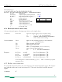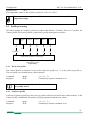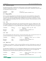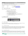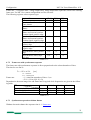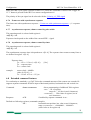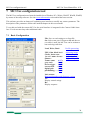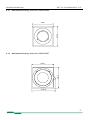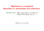
1
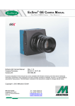
MC132x
High Speed CMOS GigE Vision Camera
MC132x Users Manual Rev. 0.23
Camera-Firmware: B2.02-V2.16-F0.81
Kamera ID Nr.: MC1324 .. MC1327
Copyright © 2006, 2007 Mikrotron GmbH
Mikrotron GmbH
Landshuter Str. 20-22
D-85716 Unterschleißheim
Germany
Tel.: +49 89 726342 00
Fax: +49 89 726342 99
[email protected]
www.mikrotron.de
General
MC132x Users Manual Rev. 0.23
Table of contents
1
General..........................................................................................................................4
1.1
1.2
1.3
1.4
1.5
1.6
1.7
2
Introduction...................................................................................................................7
2.1
2.2
2.3
2.4
3
For customers in the U.S.A. .................................................................................................................................... 4
For customers in Canada ......................................................................................................................................... 4
Pour utilisateurs au Canada ..................................................................................................................................... 4
Life Support Applications ....................................................................................................................................... 4
Declaration of conformity ....................................................................................................................................... 5
Warranty Note......................................................................................................................................................... 6
Remarks, Warnings ................................................................................................................................................. 6
Top level specifications........................................................................................................................................... 7
Electronic „Freeze Frame“ Shutter.......................................................................................................................... 7
Differences between the camera types .................................................................................................................... 8
Using the camera..................................................................................................................................................... 8
Hardware.......................................................................................................................9
3.1
GigE Vision® Interface........................................................................................................................................... 9
3.1.1
Serial command interface ................................................................................................................................... 9
3.1.2
GENICAM® command interface....................................................................................................................... 9
3.2
Power supply........................................................................................................................................................... 9
3.3
Status LED .............................................................................................................................................................. 9
4
Getting started.............................................................................................................11
4.1
5
Initial setup .................................................................................................................12
5.1
5.2
5.3
5.4
5.5
6
First steps .............................................................................................................................................................. 11
Serial number and firmware revision .................................................................................................................... 12
PowerUpProfile..................................................................................................................................................... 12
Camera Profile ...................................................................................................................................................... 12
Factory profile....................................................................................................................................................... 12
User profile............................................................................................................................................................ 12
Configuration..............................................................................................................13
6.1
6.1.1
6.1.2
6.1.3
6.1.4
6.2
6.2.1
6.2.2
6.2.3
6.2.4
6.2.5
6.3
6.3.1
6.3.2
6.3.3
6.4
6.4.1
6.4.2
6.4.3
6.5
6.5.1
6.5.2
6.5.3
6.5.4
6.5.5
6.6
6.6.1
Commands............................................................................................................................................................. 13
Table of commands .......................................................................................................................................... 14
RESET of the camera ....................................................................................................................................... 14
Acknowledge response..................................................................................................................................... 14
Baud rate........................................................................................................................................................... 15
Read camera information ...................................................................................................................................... 15
Read serial number and firmware revision ....................................................................................................... 15
Read identifier .................................................................................................................................................. 15
Read complete camera settings......................................................................................................................... 16
Read single values of camera setting................................................................................................................ 17
Reading camera temperature ............................................................................................................................ 17
Profile processing.................................................................................................................................................. 18
Write user profile.............................................................................................................................................. 18
Load user profile .............................................................................................................................................. 18
Load factory profile.......................................................................................................................................... 19
Image quality......................................................................................................................................................... 19
FPN................................................................................................................................................................... 19
Gain .................................................................................................................................................................. 19
Black Level....................................................................................................................................................... 19
Image size and position ......................................................................................................................................... 20
Address of the first line .................................................................................................................................... 20
Number of lines ................................................................................................................................................ 20
Address of the first pixel of a line .................................................................................................................... 20
Address of the last pixel of a line ..................................................................................................................... 21
Tracking ........................................................................................................................................................... 21
Clock selection ...................................................................................................................................................... 21
Arbitrary selection of sensor and pixel clock ................................................................................................... 22
2
General
MC132x Users Manual Rev. 0.23
6.6.2
Image Format/Speed change ............................................................................................................................ 22
6.7
Exposure control ................................................................................................................................................... 22
6.7.1
Type of exposure .............................................................................................................................................. 22
6.7.2
Frame rate with synchronous exposure ............................................................................................................ 23
6.7.3
Synchronous operation without shutter ............................................................................................................ 23
6.7.4
Synchronous operation with shutter ................................................................................................................. 24
6.7.5
External synchronisation with synchronous exposure...................................................................................... 24
6.7.6
Frame rate with asynchronous exposure........................................................................................................... 25
6.7.7
Asynchronous exposure, shutter control by pulse width .................................................................................. 25
6.7.8
Asynchronous exposure, shutter control by timer ............................................................................................ 25
6.8
Extended command features ................................................................................................................................. 25
6.9
Special fpga registers ............................................................................................................................................ 26
6.10
Firmware ............................................................................................................................................................... 26
6.10.1
Update firmware microcontroller application.............................................................................................. 26
6.10.2
Update FPGA firmware............................................................................................................................... 27
6.10.3
Firmware update procedure ......................................................................................................................... 27
6.11
Horizontal pixelbinning......................................................................................................................................... 28
6.12
Vertical pixelbinning............................................................................................................................................. 28
6.13
Digital gain............................................................................................................................................................ 28
6.14
External clock input .............................................................................................................................................. 29
6.15
Polarity of EXP-signal .......................................................................................................................................... 29
6.16
Test image ............................................................................................................................................................. 29
6.17
Image counter........................................................................................................................................................ 29
6.18
ImageBLITZ® shutter release............................................................................................................................... 30
6.18.1
ImageBLITZ® processing ........................................................................................................................... 30
6.18.2
ImageBLITZ® programming ...................................................................................................................... 30
6.18.3
ImageBLITZ® registers .............................................................................................................................. 33
6.18.4
ImageBLITZ® setup.................................................................................................................................... 33
7
MC13xx configuration tool ........................................................................................34
7.1
7.2
8
Basic Configuration............................................................................................................................................... 34
ImageBLITZ® Configuration ............................................................................................................................... 35
Mechanical dimensions ..............................................................................................36
8.1
Camera body MC132x .......................................................................................................................................... 36
8.1.1
Dimensioned drawing, side view of MC1324/25 ............................................................................................. 36
8.1.2
Dimensioned drawing, side view of MC1326/27 ............................................................................................. 36
8.1.3
Dimensioned drawing, front view of MC1324/25............................................................................................ 37
8.1.4
Dimensioned drawing, front view of MC1326/27............................................................................................ 37
8.1.5
Dimensioned drawing, rear view of MC132x .................................................................................................. 38
8.2
Lens adjustment .................................................................................................................................................... 38
8.2.1
Lens adaption ................................................................................................................................................... 38
8.2.2
Adjustable lens adapter, only for camera models with C-mount flange ........................................................... 38
8.2.3
Lens selection for camera types with C-mount flange (see table overview of cameras) .................................. 38
9
Technical Data ............................................................................................................39
9.1
9.2
9.3
9.3.1
9.3.2
9.4
9.4.1
9.5
Spectral response................................................................................................................................................... 40
Sensitive area of a pixel ........................................................................................................................................ 41
Connector pinning ................................................................................................................................................. 42
Gigabit Ethernet Connector .............................................................................................................................. 42
Circular power connector, 12-pin ..................................................................................................................... 42
Frequency selection............................................................................................................................................... 43
Table of clock frequency codes ........................................................................................................................ 43
Programming sequence, factory profile f3 ............................................................................................................ 45
3
General
MC132x Users Manual Rev. 0.23
1 General
1.1 For customers in the U.S.A.
This equipment has been tested and found to comply with the limits for a Class A digital device, pursuant to Part 15 of the FCC Rules. These limits are designed to provide reasonable protection against
harmful interference when the equipment is operated in a commercial environment. This equipment
generates, uses, and can radiate radio frequency energy and, if not installed and used in accordance with
the instruction manual, may cause harmful interference to radio communications. Operation of this
equipment in a residential area is likely to cause harmful interference in which case the user will be required to correct the interference at his own expense. You are cautioned that any changes or modifications not expressly approved in this manual could void your authority to operate this equipment. The
shielded interface cable recommended in this manual must be used with this equipment in order to
comply with the limits for a computing device pursuant to Subpart J of Part 15 of FCC Rules.
1.2 For customers in Canada
This apparatus complies with the Class A limits for radio noise emissions set out in Radio Interference
Regulations.
1.3 Pour utilisateurs au Canada
Cet appareil est conforme aux normes Classe A pour bruits radioélectriques, spécifiées dans le Règlement sur le brouillage radioélectrique.
1.4 Life Support Applications
These products are not designed for use in life support appliances, devices, or systems where malfunction of these products can reasonably be expected to result in personal injury. Mikrotron customers using or selling these products for use in such applications do so at their own risk and agree to fully indemnify Mikrotron for any damages resulting from such improper use or sale.
4
General
MC132x Users Manual Rev. 0.23
1.5 Declaration of conformity
Manufacturer:
Mikrotron GmbH
Address:
Landshuter Str. 20-22
85716 Unterschleissheim
Deutschland
Product:
camera
MC1324, MC1325, MC1326, MC1327
The dedicated products conform to the requirements of the Council Directives 2004/108/EG for the
approximation of the laws of the Member States relating to electromagnetic consistency. The following
standards were consulted for the conformity testing with regard to electromagnetic consistency.
EC regulation
Description
EN 61000-6-3
EN 61000-6-1
Electromagnetic compatibility
Immunity
Unterschleissheim, August 04th. 2006
Mikrotron GmbH
Dipl.-Ing. Bernhard Mindermann
President of Mikrotron
5
General
MC132x Users Manual Rev. 0.23
1.6 Warranty Note
Do not open the body of the camera. The warranty becomes void if the body is opened.
1.7 Remarks, Warnings
This document contains important remarks and warnings. See the corresponding symbols:
L
*
Important remark
Attention, Warning
6
Introduction
MC132x Users Manual Rev. 0.23
2 Introduction
The CMOS high speed camera MC132x is a high resolution camera with 1280 x 1024 pixel. Benefits of
CMOS technology are high speed, random access to pixels with free programmability and low power.
The camera uses industry-standard C-Mount lenses. The sensor diagonal is 1,25“ with square pixels
measuring 12µm.
Free programmability means that the user is free to define the region of interest by size and position and
the speed of data output. The frame rate can be selected between 25 fps and several thousand fps
depending on resolution and video data width.
With a resolution of 1280 x 1024 pixel, 80 fps can be output via the Gigabit Ethernet Interface. Parameter sets are called “profiles” and stored in non volatile memory.
2.1 Top level specifications
•
•
•
•
•
•
•
•
•
•
•
•
•
•
high resolution: 1.280 x 1.024 pixel CMOS sensor
with 1300 A/D converters
up to 1.024 gray levels
up to 80 full frames/s
up to 500 frames/s using data reduction algorithms
arbitrary region of interest
high sensitivity
12μm square pixels
electronic “Freeze Frame” shutter
low blooming
programmable via serial link
patented ImageBLITZ® image trigger
asynchronous trigger
download customer specific FPGA preprocessing firmware
small, compact housing
wide power supply range
2.2 Electronic „Freeze Frame“ Shutter
Preceding exposure, the contents of all light sensitive elements is cleared. When exposure terminates,
accumulated charge is transferred to an analog memory associated which each pixel. It stays there until
it is read out (and discharged) by the A/D conversion cycle.
As all light sensitive elements are exposed at the same time, even fast moving objects are captured
without geometric distortion.
7
Introduction
MC132x Users Manual Rev. 0.23
2.3 Differences between the camera types
The CMOS cameras are available in different versions depending on the supported features monochrome/color or Base/Full Camera Link ® interface, lens connection to C-mount or changeable lens
adapter C-mount/F-mount.
Features Data
width
Type
(bits)
MC1324
MC1325
MC1326
MC1327
8
8
8
8
Color/
Mono
M
C
M
C
Max BWidth
110 Mbyte/s
110 Mbyte/s
110 Mbyte/s
110 Mbyte/s
C/F-Mount
max. frame rate@ Imagelens adaption 1280 x 1024
BLITZ®
C
C
F
F
Table 2.3-1
80 fps
80 fps
80 fps
80 fps
Image preprocessing
supported
+
+
+
+
+
+
+
+
+ ... supported
- ... not supported
2.4 Using the camera
There are no serviceable parts inside the camera.. The camera may not be opened, otherwise guarantee
is lost.
Use dry, soft lens-cleaning tissue for cleaning lenses and, if necessary, the sensors window.
8
Hardware
MC132x Users Manual Rev. 0.23
3 Hardware
3.1 GigE Vision® Interface
GigE Vision® is designed for digital cameras in machine vision applications. This interface can transfer
data at a rate of 110 Mbytes/sec.
The GigE Vision® chipset and software is designed and implemented by Pleora Tech. Inc. the leading
supplier of GigE Vision technology. Please refer to the PT1000 documentation for further information.
3.1.1
Serial command interface
The camera is controlled by an ascii-based serial protocol, wrapped by the Pleora IPORT engine.
3.1.2 GENICAM® command interface
Implemented camera specific GENICAM® features:
Feature name
CameraHeadSensorClock
CameraHeadPixelClock
CameraHeadDigitalGain
CameraHeadSaveAsPowerUp
CameraHeadReset
Corresponding serial command
:S4xxxxx
:S6xxxxx
:r700x
:pc
:c
Reference
Clock selection
Clock selection
Digital gain
Profile processing
RESET of the camera
3.2 Power supply
The camera needs a DC supply voltage between 8 … 24 V at a power consumption of 5,0 Watt max.
See also Connector pinning .
*
Before applying power to the camera we strongly recommend to verify the used pins of the
power connector, the polarity (+/-) of the leads and the supply voltage.
The camera may only be used with a supply voltage according to the camera specification.
Connecting a lower or higher supply voltage, AC voltage, reversal polarity or using wrong
pins of the power connector may damage the camera. If doing so, the warranty will expire
immediately.
3.3 Status LED
A dual colour LED on the camera backplane shows the operating condition of the MC132x.
LED orange...
The MC132x is configuring the internal FPGA. No other activity is possible.
9
Hardware
MC132x Users Manual Rev. 0.23
LED green...
The MC132x is fully operational.
LED off...
If LED is off, despite the camera is powered, the FPGA configuration data is reloaded via the serial interface and stored in internal EEPROM. No other activity
is possible.
red LED that the FPGA could not be loaded because of wrong FPGA configuration data. Try to reload configuration data.
LED red...
10
Getting started
MC132x Users Manual Rev. 0.23
4 Getting started
Before starting to operate the camera, make sure that the following equipment is available:
•
•
•
•
Camera MC132x
C-Mount/F-Mount Lens
Mikrotron Support CD
Image processing system, e.g.: PC and Software
L
For GigE Interface the Intel MT1000 Chipset is recommended
Additional items:
• 1 GigE cable (CAT6 recommended)
• 1 Power supply 12VDC, 0.5A min
• 1 power cable
L
To specify cables see chapter Connector pinning.
4.1 First steps
1.
2.
3.
4.
5.
Switch off the image processing system
Connect GigE cable between camera and PC.
Connect power cable.
Unscrew dust protection cover, screw in lens.
Switch on the image processing system and camera power supply
11
Initial setup
MC132x Users Manual Rev. 0.23
5 Initial setup
The MC132x is delivered with initial parameters and therefore does not need to be configured via the
serial link.
5.1 Serial number and firmware revision
Serial number and firmware revision is provided in MC132x non volatile memory. Use :v command
(Read serial number and firmware revision) to read serial number and firmware revision. The serial
number is also marked on the type plate of the camera.
5.2 PowerUpProfile
The PowerUpProfile is the setting of all registers, which is loaded from non-volatile memory during
power-up and software reset. The content of the PowerUpProfile is loaded into the Camera Profile.
5.3 Camera Profile
The actual set of parameters is called Camera Profile. All changes of parameters by the serial link is
reflected in the Camera Profile. The Camera Profile can be saved to 8 user profiles or one
PowerUpProfile by command. It is loaded from 8 user profiles or 8 factory profiles or the
PowerUpProfile. The camera profile is volatile and must be stored to the PowerUpProfile to be reactivated on next power up or software reset.
5.4 Factory profile
The factory profile can be read but not written by the user. They are factory preset to the settings of table below.
Profil-Nr.
Resolution
in pixel
0
1
2
3
4
5
6
7
100 x 100
240 x 240
640 x 480
1280 x 1024
640 x 480
1280 x 1024
640 x 480
1280 x 1024
Data width per
Pixel
in bit
8
8
8
8
8
8
10
10
Frame rate
in fps
4.852
1.011
202
47
202
47
48
23
Video data
width
in Mbyte/s
48,5
58,2
62,1
61,6
62,1
61,6
28,1
57,5
Table 5-1
5.5 User profile
The user can store up to eight User profiles in non volatile memory. All load or write commands exchange data between the PowerUpProfile and one of the four user profiles. The user profiles are factory
preset to the factory profiles.
12
Configuration
MC132x Users Manual Rev. 0.23
6 Configuration
The MC132x has 15 FPGA registers, r1..rfh , each 10 bit wide, 16 x 32bit registers, eight D/A registers,
a1..a8, 8-bit wide, and two clock code registers, each 3 x 8bit wide. The contents of all the above registers is called a profile. There is space in non volatile memory for 17 profiles: one PowerUpProfile, 8
user profiles and 8 factory profiles.
Any change of a specific register through the serial interface is immediately processed and written to
the volatile part of the memory and gets lost when power goes down. A command must be used to store
the actual setting in non volatile memory. After power-up the PowerUpProfile is loaded from the nonvolatile to the volatile part of the memory (Camera profile).
A load or write command exchanges data between the PowerUpProfile and one of the eight user profiles. The eight factory profiles can be read but not be written by any command. All values are given in
hexadecimal notation, e.g.: 0xff or 0ffh = 255.
6.1 Commands
ASCII strings are used to change camera parameters. All commands start with a colon, followed by one
selection character and a value in hexadecimal notation with two or three ASCII characters.
After a command has been recognized, processing is immediate, for all commands but the save type
commands (:px). These need a EEPROM write time of app 1ms. An answer is provided with read type
commans (:v, :w, :W) or, if the command “command acknowledge flag” is set, after processing of each
command an ACK or NAK character. Processing of wrong command is stopped immediately on recognizing the error. A new command must start with a colon.
13
Configuration
6.1.1
MC132x Users Manual Rev. 0.23
Table of commands
Syntax
:a<n><xx>
Range
<n> = 1...8
<xx> = 0...ffh
<n> = „y“,“Y“,“n“,“N“
:A<n>
:b<n>
Answer
ACK*
ACK*
<n> = 0...4
ACK*
--
ACK*
:c
:e...
:ERASE<ccc>
-<ccc> = “APP”, “EPCS1”
:f<n>
<n> = 0...7
ACK*
:g<n>
:l<nn><xxxxxxxx>
<n> = 0...7
<nn>=00..02
<xxxxxxxx>=32bit value
<n> = 0...7
ACK*
ACK*
<n> = 1...fh
<xxx>= 000...3ff
<xxxxxx> = 6 Byte Code
<n> = 00..7fh
<m> = 00..ffh
---
ACK*
:p<n>
:r<n><xxx>
:S<xxxxxx>
:t<n><m>
:T
:v
:V
:w
:W
:Z<c><…>
---
ACK*
ACK*
ACK*
+50.5
#12345-B2.02-V1.10F1.29
-1324000003433
-camera profile:
44 bytes in hex
-Camera profile:
44 bytes in ASCII
<c> = “a”, “c”, “l”, “r”
register value in ascii,
<…>= register no., depending
different formats
on <c>
ACK*
…
6.1.2
RESET of the camera
Description
Set one of eight analog voltages for the sensor
En- or disable a command acknowledge or not acknowledge (ACK or NAK)
Select baud rate:
0=9600 Bd (default setting), 1=19.2 kBd,
2=38.4 kBd, 3=56.8 kBd, 4=115.2 kBd
RESET and new Initialization of the camera, new load
of PowerUpProfile. Duration: some seconds
Transmit & save a new FPGA configuration
Erase of camera internal firmware,
CAMERA STOPS WORKING, READ COMMAND
DESCRIPTION BEFORE EXECUTING !
Reload one of eight, factory defined and calibrated
profiles to PowerUpProfile.
Reload one of eight user profiles to PowerUpProfile
Extended registers for special use (e.g. direct input of
camera settings), 32 bit values, as 6 ASCII char
Save PowerUpProfile to one of eight user profiles,
allow app. 1ms save time.
Write a FPGA - register
Program sensor and pixel clock directly.
Short setting of X- position in units of 10 pixel and Yposition in units of 4 lines.
Read temperature
Read serial number (#) and
firmware versions
Read identifier
Read actual Camera Profile,
data output in hex
Read actual Camera Profile,
data output in ASCII
Read single register values
ACK (acknowledge, 06 hex) or NAK (not acknowledge, 15 hex) will only be sent if the response
was enabled first by command :A<n>.
For reconfiguring the camera without power down/up there is a command for resetting the camera. The
camera will start-up new, configure fpga and load the power-up profile. Additionally some volatile settings will be adjusted to the default values, e.g. baud rate.
Command:
:c
camera reset
Response:
ACK
if enabled by separate command :A<n>
6.1.3
Acknowledge response
Several commands do only adjust the camera without any response of the camera. To get an answer of
the camera an acknowledge response can be en- or disabled. The default setting for camera start-up is
“no response”. After power-up or reset of the camera the Acknowledge response is disabled. The response is volatile and must be separately enabled by the following command.
Command:
:A<n>
<n> = “Y”, “y”, “N”, “n”
“Y”, “y” … response enabled
“N”, “n” … response disabled
14
Configuration
Response:
MC132x Users Manual Rev. 0.23
if command is “:AY” or “:Ay”
ACK = 06 hex, in hex
NAK = 15 hex, in hex
All commands, which can answer with a acknowledge reponse are shown in the command table.
*
ACK
Provided that acknowledge response is enabled, the camera will only send ACK
or NAK if it receives a known command structure with at least a colon. Sending
any characters without command syntax will not be responded.
6.1.4 Baud rate
The baud rate of the serial communication may be adjusted from low to higher speed. The camera always starts with 9.600,8,n,1,- (9.600 Bd, 8 data bits, no parity, 1 stop bit). The adjustment of the baud
rate can be changed, but the setting is volatile and will be reset to 9.600 Bd if power-up or reset of the
camera occurs.
Command:
:b<n>
<n> = 0 ... 4
0 = 9.600 Bd (default, power-up, reset)
1 = 19.200 Bd
2 = 38.400 Bd
3 = 57.200 Bd
4 = 115.400 Bd
Response:
ACK
if enabled by separate command :A<n>
6.2 Read camera information
6.2.1
Read serial number and firmware revision
The serial number and the firmware revision can be read with the :v command.
Command:
Response(e.g.):
:v
#01234-B2.02-V2.02-F0.71
Serial number
of the camera
Microcontroller bootloader
firmware version
6.2.2
FPGA firmware version
Microcontroller application
firmware version
Read identifier
The identifier offer information about the camera type and camera functions. It consists of 8 bytes,
which are delivered as 16 ascii characters.
Command:
Response (e.g.):
:V
1324000000000000
definition of additional functions or features, 4 bytes
camera type, e.g. 1324 = MC1324
15
Configuration
MC132x Users Manual Rev. 0.23
Definition of functions or features:
cccc0000000000ss
00
…
not defined
cccc …
camera type of camera label at the rear housing of the camera, e.g.
1324, 1325, 1326, 1327
ss
…
sobel filter
Function
bit
not used
not used
not used
Sobel bin+dir (2bit per pixel)
Sobel binary (1bit per pixel)
Sobel bin+dir (8bit per pixel)
Sobel (8bit per pixel)
Target data (proprietary)
7
6
5
4
3
2
1
0
value of each
bit of ss in hex
80
40
20
10
08
04
02
01
description
1 … enable, 0 … disable
1 … enable, 0 … disable
1 … enable, 0 … disable
1 … enable, 0 … disable
1 … enable, 0 … disable
1 … enable, 0 … disable
1 … enable, 0 … disable
1 … enable, 0 … disable
Example: Sobel filter with all features: ss = ff
6.2.3
Read complete camera settings
The complete, actual camera settings can be read out . The answer are the values of all camera registers.
Command:
:w
:W
Output as hexadecimal digits
Output as ASCII-String
Example for ":w" (output as hex digits, 110 Databytes + CR + LF):
6d6448c66500650061008541898c0000
03f f03f f0000007f 0030000000000000
00000000000000000000000000000000
00000000000000000000000000000000
00000000000000000000000000000000
00000000000000000000000000000000
000000000000000000000000↵
15x10bit registers
r1... rf
16x32bit registers
m0...mf
CR+LF
Example for ":W" (output as ASCII string, 91 Bytes total, 88 databytes, 1x CR preceding the databytes,
1x CR after 32 ASCII-characters and 1x CR after 64 ASCII- characters):
↓6d6448c66500650061008541898c0000↓
03f f03f f0000007f 0030000000000000↓
00000000000000000000000000000000↓
CR
00000000000000000000000000000000↓
00000000000000000000000000000000↓
00000000000000000000000000000000↓
000000000000000000000000↵
Assignment of data to camera parameters:
analog settings
6d6448c665006500 61008541898c 0000
03f f03f f0000007f 0030000000000000
000000000000000000000000↵
Codes for pixeland Sensorclock
image size & position
16
Configuration
MC132x Users Manual Rev. 0.23
Transmitted bytes:
A1 A2 A3 A4 A5 A6 A7 A8 Sa1 Sa2 Sa3 Sb1 Sb2 Sb3
R1h R1l ... R15h R15l M0hh M0hl M0lh M0ll … Mfhh Mfhl Mflh Mfll↵
A1...A8
Sa1 Sa2 Sa3
Sb1 Sb2 Sb3
R1…R15
R1h ...
R1l ...
M0…Mf
M0hh
M0hl
M0lh
M0ll
↵ ...
analog settings
3 Bytes frequency codes of pixelclock
3 Byte frequency codes for sensorclock
image size & position (r registers)
high Byte Register1
low Byte Register1
fpga registers (m registers)
1. byte of m register no. 0, MSB
2. byte of m register no. 0
3. byte of m register no. 0
4. byte of m register no. 0, LSB
CR+LF (0dh + 0ah)
(see 6.7)
(see 6.7)
Abb. description hex. Code
CR carriage return
0d
LF
line feed
0a
6.2.4 Read single values of camera setting
All camera internal registers of settings may also be read as single values.
Command:
:Z<c><xx>
request for single register value of camera setting
<c> …
‘a’, ‘c’, ‘r’, ‘m’ (ascii characters)
<xx> …
extension, which can differ in dependence
of the wanted camera setting
Valid commands:
:Za<n>
output of value of analog register, in ascii characters
<n> …
1 - 8 (ascii character)
output of sensor clock code
output of pixel clock code
output of fpga registers r,
<xx> …
01 – 0f (hex, in ascii characters)
output of special fpga registers m,
<n> …
0 – f (hex, in ascii characters)
:Zcs
:Zcp
:Zr<xx>
:Zm<n>
Response:
for :Za<n>
for :Zcs
for :Zr<xx>
for :Zm<n>
, e.g. 6d↓
, e.g. 41bb0b↓
, e.g. 03ff↓
, e.g. 00000000↓
(hex, 2 ascii characters + CR)
(hex, 6 ascii characters + CR)
(hex, 4 ascii characters + CR)
(hex, 8 ascii characters + CR)
or for incomplete or invalid command (e.g. :Zx):
command :A<n>
6.2.5
NAK if enabled by separate
Reading camera temperature
To control the temperature inside , the camera disposes of an internal temperature sensor. The temperature inside the camera can be read out in steps of 0.5°. The value is delivered in ASCII characters
signed.
Command:
:T
17
Configuration
MC132x Users Manual Rev. 0.23
Response(e.g.):
+34.0
The temperature sensor is able to deliver values of –128°C to +128°C.
*
Take care that the temperature of the camera does not exceed the specified case
temperature range.
6.3 Profile processing
All camera settings are loaded or stored as complete data blocks (= Profiles). There are 17 profiles, the
Camera profile, the PowerUpProfile, eight factory profiles and eight user profiles.
PowerUpProfile
factory
profiles
0...7
user
profile 0
:pc
user
profile 1
user
profile n
user
profile 7
:p0
:p1
:pn
:p7
:g0
:g1
:gn
:g7
f0..7
:gc
or power on
camera profile (programs to camera logic)
configuration commands
:a..z[parameter]
6.3.1
Write user profile
The Camera Profile is transferred to one of the eight user profiles (0…7) or the power-up profile (c).
The user profiles are located in non volatile memory.
Command:
Response:
L
6.3.2
:p<n>
ACK
<n> = 0 ... 7,c
if enabled by separate command :A<n>
Issue this command only, if the Camera Profile was
successfully tested.
Load user profile
Load one of eight user profiles or the power-up profile, which are located in non volatile memory, to the
Camera Profile. Additionally all registers will be programmed with the new values.
Command:
Response:
:g<n>
ACK
<n> = 0 ... 7, c
if enabled by separate command :A<n>
18
Configuration
6.3.3
MC132x Users Manual Rev. 0.23
Load factory profile
The eight factory profiles, located in non volatile memory, can be read but not changed by the user.
With this command factory profile no. <n> is loaded into Camera Profile. Additionally all registers will
be programmed with the new values.
Command:
Response:
:f<n>
ACK
<n> = 0 ... 7
if enabled by separate command :A<n>
6.4 Image quality
There are eight analog parameters to adjust the first stage of the sensor and influence image quality.
Five of them are calibrated for getting excellent image quality and should not be changed. Three parameters are also preset for good image quality. Although it’s not necessary to change them, it can be
useful to optimize them depending on the used camera mode and speed. The three parameters are FPN,
Gain, and Black up.
6.4.1 FPN
The Fixed Pattern Noise setting reduces the fixed pattern noise that is typical to CMOS sensors. This
level might be changed if the sensor clock frequency is changed. For adjustment set the lens out of focus and to a medium grey level. Lower FPN until a heavy pattern appears. Then raise by a few points.
Command:
:a1<x1x0>
Response:
Example:
ACK
:a164
6.4.2
<x1x0> : Range 00 .. ff (hex), typ. 55h ... 80h,
ASCII char
if enabled by separate command :A<n>
set register a1 to 64 (hex)
Gain
This is the threshold for the A/D converters. To increase the gain the value of a2 must be lowered. Values below 30h will lead to oversensitive images and are not recommended to set.
Command:
:a2<x1x0>
Response:
Example:
ACK
:a264
<x1x0> :
Range 00 ... ff (hex), typ. 30 ... 80 (hex),
ASCII char
if enabled by separate command :A<n>
set register a2 to 64 (hex)
6.4.3 Black Level
If no Black Level is adjusted (= 00 hex), each pixel will have an offset, which reduces the contrast. For
excellent image quality it’s recommended to adjust Black Level to subtract this offset from each pixel
value.
For adjustment of the Black Level it’s recommended to darken the sensor (closed lens) and increase the
Black Level value till all pixel values are touching 0 level. The Black Level can vary slighty with
changing the sensor clock and should be optimized for each selected speed.
Command:
:a5<x1x0>
Response:
ACK
<x1x0>:
Range, typ. 00h ...ff (hex), typ. 30… 80 hex
ASCII char
if enabled by separate command :A<n>
19
Configuration
MC132x Users Manual Rev. 0.23
6.5 Image size and position
Image size and position within the sensor is defined by four parameters:
Bit(s)
r1[9..0]
r3[9..0]
r4[6..0]
r5[6..0]
6.5.1
Description
Number of first line, 0..3FDh
Number of lines, 0..3FFh
Address/10 of the first pixel
Address/10 of the last pixel
Table 6.5-1
Address of the first line
Register r1 defines the vertical start position of the ROI (region of interest ) within the sensor size. It’s
the first line to be displayed.
Command:
Response:
:r1<x2x1x0>
ACK
<x2x1x0> ... Range 000h ...3fdh
if enabled by separate command :A<n>
Example:
:r1100
= 256 (dec) + 1 Ö image starts at line 257
L
6.5.2
If dual column binning is activated, r1 is doubled
within the camera logic.
Number of lines
Register r3 defines the vertical size of the ROI (region of interest ) within the sensor size. It’s the
number of lines to output.
Command:
Response:
:r3<x2x1x0>
ACK
<x2x1x0> ... Range 000 h ...3ffh
if enabled by separate command :A<n>
Example:
:r31ff
= 511 (dec) +1
L
6.5.3
Ö display 512 lines
The sum of r1 and r3 must be ≤ 0x3ff/1023 or
0x1ff/511 if dual column binning is activated!
Address of the first pixel of a line
Register r4 defines the start of horizontal start position of the ROI (region of interest ) within the sensor
size. It’s the leftmost pixel. The value is the pixel address divided by ten.
Command:
Response:
:r4<x2x1x0>
ACK
<x2x1x0> ... Range 000h ...7fh
if enabled by separate command :A<n>
Example:
:r4020
= 32 (dec) * 10
Calculation of the value of r4:
Ö line start at pixel 320 (dec)
Value of r4 = Pixel-Nr./10
20
Configuration
6.5.4
MC132x Users Manual Rev. 0.23
Address of the last pixel of a line
Register r4 defines the horizontal end position of the ROI (region of interest ) within the sensor size. It’s
the rightmost pixel. The value is the pixel address divided by ten.
Command:
Response:
:r5<x2x1x0>
ACK
<x2x1x0> ... Range 000h ...07fh
if enabled by separate command :A<n>
Example:
:r505f
= 95 (dec) * 10
Ö line end at pixel 790 (dec)
Calculation of the value of r5:
Value of r5 = Pixel-Nr./10
Calculation of horizontal size:
e.g.: r4 = 010, r5=04f
(r5 – r4 + 1) * 10
(95 - 32 + 1) * 10 = 640 pixel per line
L
6.5.5
The difference r5 - r4 must be in the range: 0 ≤ r5-r4 ≤ 7fh .
Tracking
For rapid window movement even at slow baud rates a short command is provided..
command:
:t<n>,<m>
<m> = X-position in pixel/10,
range 00h ...07fh
<n> = Y-position in lines / 4,
range 00h ...0ffh
Response:
ACK
if enabled by separate command :A<n>
6.6 Clock selection
The MC132x is equipped with a 2-channel programmable clock synthesizer. One channel controls clock
frequency of the sensor (sensorclock, Fsens), the other controls the frequency of the pixel clock (pixelclock, Fpix). These independent clocks allow an always optimal ratio depending on the product of
(image size x image frequency) and the data rate on the output.
As the sensor outputs 10 pixel per clock a sensor clock of 6.6MHz could be chosen. Because the sensor
can run up to a clock frequency of 66 MHz only 1/10 of the sensors possible speed would be used. To
make use of the maximum sensor clock and maintaining the maximum data rate on the output, just 120
(1280/10 rounded to steps of 10) from the possible 1280 pixel per line can be selected.
Therefore the ratio of Fsens and Fpix depends on the selected line length:
Fsens <= (Fpix • 1280) / (5 • line length)
or if 100 pixel line length is chosen:
Fsens = (33 • 1280) / (5 • 100) = 70,4 MHz
As this exceeds the maximum sensor clock frequency, Fsens is chosen as 66 MHz and Fpix as 33 MHz.
21
Configuration
6.6.1
MC132x Users Manual Rev. 0.23
Arbitrary selection of sensor and pixel clock
Sensor and pixel clock can be set to any value, the product of: (sensor clock • line length/1280) must
always be smaller (about 10%) than the qoutient: (pixel clock / 2).
Command
:S <x0>
Response:
ACK
6.6.2
<x0> ... 6 characters, as described in
chapter Frequency selection
if enabled by separate command :A<n>
Image Format/Speed change
There are several steps necessary for a change of image format:
i. Disable sensor controller with :r6[4] = 0.
ii. Set image size with (:r1,:r2, :r3, :r4, :r5).
iii. If new sensor clock = old sensor clock:
1. Do not set pixel clock nor sensor clock.
iv. If new sensor clock > old sensor clock:
1. Set new pixel clock (:S6…..), then new sensor clock (:S4….).
v. If new sensor clock < old sensor clock:
1. Set new sensor clock (:S4…..), then new pixel clock (:S6….).
vi. Reenable sensor controller (:r6[4]=1).
6.7 Exposure control
Exposure control is selected with register r6[7..4] and register r2[9..0].
Bit(s)
r6[7..4]
r2[9..0]
Description
Type of exposure
Exposure time
table 6-1
6.7.1
Type of exposure
The MC132x can expose the images synchronous or asynchronous. An external signal on CC1 can be
used to synchronize MC132x cameras to each other or to an external event.
6.7.1.1 Synchronous exposure
Synchronous exposure means that the next image is exposed, while the current image is output. This
mode provides fastest frame rate while maintaining maximum exposure time as long as 1/frame rate. If
an external synchronization signal is input on CC1 its frequency range can be between 30Hz and the
selected free running frame rate. Use MC13xx camera configuration tool for selection.
6.7.1.2 Asynchronous exposure
With asynchronous exposure, an external signal starts exposure, and the exposed image is output immediately after the exposure ends. Exposure time is defined either by an internal timer or by the width of
the external EXP (CC1) signal. The time between two consecutive EXP (CC1) edges can be indefinite.
22
Configuration
MC132x Users Manual Rev. 0.23
Frame rate = 1/(exposure time + image output time). Image output time equals the selected free running
frame rate. Use MC13xx camera configuration tool for selection.
The following registers select exposure type:
Register Bits
:r6[7..4]
camera stop
xxx0
Synchronous without elec0001
tronic shutter
Synchronous with electronic
0011
shutter
Synchronous with electronic
0011
shutter and external synchronisation signal, positive edge
Synchronous with electronic
0011
shutter and external synchronisation signal, negative edge
Asynchronous, pulsewidth,
1011
positive edge
Asynchronous, pulsewidth,
1011
negative edge
Asynchronous, timer, positive 1111
edge
Asynchronous, timer, nega1111
tive edge
Table 6.7-1
:r7[8]
x
0
:rf[0]
x
0
0
0
0
1
1
1
0
0
1
0
0
0
1
0
6.7.2 Frame rate with synchronous exposure
The frame rate with synchronous exposure is direct proportional to the selected number of lines.
The time for one line is:
Tzz = 1/Fsens • 136
[sec]
Tzz ...time/line
Fsens... Sensorclock
= 1 / (time/line • number of lines+1) or:
= Fsens/ (136 • (r3[9..0] +2))
Dependencies between image size and frame rate for typical clock frequencies are given in the following table:
image size
100x100 240x240 640x480 1280x1024
Frame rate:
Sensorclock (MHz)
Time/line [µs]
Frames/s
66
33
2,06
4,12
4.852
1.011
Table 6.7-2
13,2
10,3
202
6,6
20,6
47
6.7.3 Synchronous operation without shutter
Without electronic shutter the exposure time is 1 / frame rate.
23
Configuration
MC132x Users Manual Rev. 0.23
6.7.4 Synchronous operation with shutter
In the sensor is implemented a freeze frame shutter, which allows to reduce the exposure time in steps
of one line. The minimum value of the exposure time is the duration of 2 line periods, which is determined by the value of r2 (min. 001h).
Command:
Response:
:r2<x2x1x0>
ACK
<x2x1x0> ... Range 001h ...3ffh
if enabled by separate command :A<n>
Exposure time TB :
TtB = r2 • TZZ -TZZ / 2
TB ...
r2 ...
TZZ ...
exposure time in s
value of register 2
time/line
Tzz = 1/Fsens * 136
Ttzz ... Time/line
Fsens... sensor clock
B
[s]
Typical exposure times:
Sensor clock
frequency (MHz)
66
33
13,2
6,6
6.7.5
Time/line
r2
(µsec)
@ 1/5.000 s
2,06
97
4,12
49
10,3
19
20,6
10
Table 6.7-3
r2
@ 1/10.000 s
49
24
10
5
External synchronisation with synchronous exposure
MC132x cameras can be synchronized to an external signal that is input on the EXP (TRIG) signal. The
strobe output signal of a MC132x “master camera” can be used for that purpose.
See timing diagram: Synchronous exposure with external synchronisation via TRIG
The cameras frame rate must be set to a frequency slightly higher than the maximum frequency of the
synchronization signal. The minimum frequency should be higher than 30Hz.
Command:
Response:
000 … deselect external sync signal
001 … select external sync signal
This is an example for enabling this function. Depending on the wanted camera
mode it can be necessary to add additional bits of this register
.
ACK
if enabled by separate command :A<n>
Command:
:rf001
Response:
:rf001
ACK
<0> ... deselect external sync signal
<1> ... select external sync signal
if enabled by separate command :A<n>
24
Configuration
MC132x Users Manual Rev. 0.23
Make sure that a sync signal is present on EXP/CC1 before this command is issued or the “trigger on
CC1” button is pressed on the MC13xx camera configuration tool.
The polarity of the sync signal can be selected with the _Polarity_of_EXP-signal
6.7.6 Frame rate with asynchronous exposure
The frame rate with asynchronous exposure = Frame rate with synchronous exposure – (1 / exposure
time).
6.7.7
Asynchronous exposure, shutter control by pulse width
This operating mode is selected with register 6:
:r6[7..4] = 0xb
Exposure time depends on the width of the external EXP – signal.
6.7.8
Asynchronous exposure, shutter control by timer
This operating mode is selected with register 6:
:r6[7..4] = 0xf
The asynchronous exposure time is dependent on :r2[9..0]. The exposure timer counts as many lines as
are defined in register :r2[9..0].
Exposure time:
TB = 1/Fsens * 136 • (1+r2[9..0])
TB ... exposure time
Fsens.. sensor clock
example:
[Sec]
sensor clock = 66MHz
value of r2[9..0] = 6
TB = 136 • 6 • 15 ns = 12,2 µs
6.8 Extended command features
For conformity to standards, e.g. GigE Vision the command structure of the camera was extended. It
supports separate commands for direct input of horizontal position, horizontal size and vertical size.
Command:
:l<nn><xxxxxxxx>
Response:
ACK
direct programming of additional 32bit registers
<nn> … no. of register,
range 00 … 02 (hex in ascii characters)
<xxxxxxxx> … 32bit value of register, hex in
ascii characters
if enabled by separate command :A<n>
Defined are following registers (command example):
:l00…
horizontal start position, hex value as ascii characters,
range (<xxxxxxxx> = ): 00000000 … 0000007e
(same value as for register r4)
25
Configuration
MC132x Users Manual Rev. 0.23
:l01…
horizontal size, hex value as ascii characters,
range: 00000000 … 00000080,
value of l01 = r5 – r4 + 1
:l02…
vertical size, hex value as ascii characters,
range: 00000000 … 00000500
value of l02 = r3 – r1 + 1
New inputs with command :l will only adjust the values of registers r1…rf and will not be stored separately in the camera profile.
6.9 Special fpga registers
The fpga also handles 16 registers, each 32 bit wide, for setting special modes or functions inside the
camera. These settings may be coupled with special features, e.g. sobel filter or customized image preprocessing inside the camera, which can be en- or disabled in dependence of camera extensions defined
in the identifier.
The 16th register is reserved. It can only read and contains the 4 LSB bytes of the identifier.
Command:
:m<n><xxxxxxxx>
<n>
… no. of register, in hex as ascii character,
range 0…e (hex)
<xxxxxxxx> … register value, in hex as ascii
character, MSB…LSB,
range 00000000…ffffffff (hex)
if enabled by separate command :A<n>
Response:
ACK
Example:
:m012345678
The setting of the m registers may change depending on the camera functions. There are no presetting.
For standard cameras the registers are preset to 0000000. If used for special features the adjustment is
described in the documentation of the special feature(s).
6.10 Firmware
The camera possesses programmable devices, which are working with some firmware packages. New
cameras were programmed with all needed firmware packages and will not need any update.
For customized firmware or additional features the camera offers the possibility to update some of the
firmware versions. The procedure of updating depends on the firmware package.
*
Do not update more than 1 firmware at the same time.
In case of updating more than 1 firmware, please start with application program,
then fpga program follows.
6.10.1 Update firmware microcontroller application
The microcontroller works with 2 programs, the bootloader and the application program.
The bootloader is the basic program of the microcontroller, which ensures some basic functions (e.g.
communication, loading application program) and cannot be changed or updated. In standard use of the
camera it will never work in the bootloader program and the version cannot be read out. It’s only used
for updating the application program.
26
Configuration
MC132x Users Manual Rev. 0.23
The application program is the active microcontroller program in the camera, which supports communication, data handling and fpga program updates.
See description of update procedure in chapter “Firmware update procedure”.
6.10.2 Update FPGA firmware
MC132x’s logic is integrated into a FPGA (Field Programmable Gate Array), which’s configuration is
stored in an EEPROM. Upon power up or a command the FPGA is loaded with this configuration. Configuration data can be downloaded via the serial interface. Mikrotron may provide configuration files
(*.ibf) on request.
After download of configuration data, this data is permanently stored in EEPROM and the FPGA is
configured with the new data. Besides a power cycle, the :c command can be used to reconfigure the
FPGA with the internally stored configuration data.
See description of update procedure in chapter “Firmware update procedure”.
6.10.3 Firmware update procedure
Before you disable the loaded firmware please ensure that you have a adequate application firmware
version to load (e.g. MC132x….A202.ibf for application firmware, MC132x…F070.ibf for fpga firmware).
(1)
Start camera and test communication, e.g. with tool press “info camera” and wait for response
(serial no. and firmware)
(2)
Select in menu “Write” “Write string to camera” and write command
- for application firmware update:
:ERASEAPP
<ENTER>
- for fpga firmware update:
:ERASEEPCS1
<ENTER>
which erases the program and for application firmware will restart the camera.
*
(3)
(4)
*
(5)
After this command the camera may not be able to deliver any images,
load/send/store register or profile data. The status led of the camera will turn to red.
For application firmware update only:
The camera now starts with the bootloader program. It is displayed during start by the status led
which blink one time during power up.
Test communication, e.g. with MC13xx in menu “Write string to camera” and command :v.
Response (e.g.):
B2.02
Select in menu “Write” “Write file to camera” and choose application file MC132x*.ibf) and
open it. The file transfer will start immediately. If the camera recognizes a newfirmware
it will switch off the status led.
Download of *.ibf file via serial link takes app. 1,5 - 2 min depending on the used
camera. There should be no loss of power or communication during this time!
Wait until file transfer is finished and the status led turns on. If the upload of the file was
successful, the led will turn to green, otherwise it will be red.
27
Configuration
(6)
MC132x Users Manual Rev. 0.23
Verify version string by reading serial no. and firmware versions (command: :v). The new
firmware version will be displayed as part of the version string. If the version is identical to
the expected the camera is ready to use for capturing images.
6.11 Horizontal pixelbinning
Pixelbinning adds the gray values of two adjacent pixels and outputs it as one pixel with double sensitivity. In X-direction only 512 pixels are needed to cover the sensors full size.
To retain aspect ratio, every second line is discarded, if this feature is not disabled by setting Bit 8 of
register 6 (:r61xx) or vertical pixelbinning is activated.
Command:
:r7010
This is an example for enabling this function. Depending on the wanted camera
mode it can be necessary to add additional bits of this register
.
Response:
ACK
if enabled by separate command :A<n>
If discarding of every other line is not disabled (:r61xx), the contents of :r1 is doubled in camera logic.
To address a specific line on the sensor, the value written into :r1 has to be divided by two and :r3 must
not exceed 1ffh.
Example:
To output 256 lines from line 128, set r1 = 63 and r3 = 255 (=0xff).
6.12 Vertical pixelbinning
Vertical pixelbinning adds the gray values of two superimposed pixel of a column. This doubles sensitivity and vertical field of view. To retain aspect ratio, in addition horizontal binning must be activated.
To activate, set bit 2 in register 6.
Command:
:r6034
This is an example for enabling this function. Depending on the wanted camera
mode it can be necessary to add additional bits of this register
.
Response:
ACK
if enabled by separate command :A<n>
6.13 Digital gain
Out of the 10-bits sensor data either the most significant 8 bits (gain 1), or bits 8..1 (gain 2), or the least
significant 8 bits (gain 4) are selected.
Command:
:r700x
x = 0: gain 1
x = 4: gain 2
x = 8: gain 4
This is an example for enabling this function. Depending on the wanted camera
mode it can be necessary to add additional bits of this register.
Response:
ACK
if enabled by separate command :A<n>
28
Configuration
MC132x Users Manual Rev. 0.23
6.14 External clock input
MC132x frequency synthesizer can use the Camera Link® used to synchronize several MC132x to one
master clock.
To activate set Bit 9 of register 7.
Command:
:r7[9] = 0, external clock input disabled
:r7[9] = 1, external clock input enabled
This is an example for enabling this function. Depending on the wanted camera
mode it can be necessary to add additional bits of this register.
Response:
ACK
*
:r7200
if enabled by separate command :A<n>
If the external reference clock is different from 3.6864 MHz, the codes for the
clock synthesizer have to be recalculated.
6.15 Polarity of EXP-signal
The polarity of the EXP-signal can be positive- or negative active. Use :r7[8] to select.
Command:
:r7100
:r7[8] = 1, negative polarity
:r7[8] = 0, positive polarity
This is an example for enabling this function. Depending on the wanted camera
mode it can be necessary to add additional bits of this register.
Response:
ACK
if enabled by separate command :A<n>
6.16 Test image
For testing of camera logic and video data transmission, sensor data can be replaced by an internal gray
scale pattern with pixel values of 0..127. Use digital gain command to see pixel values of 0..255.
Command:
:r7040
r7[6] = 0, internal gray scale pattern disabled
r7[6] = 1, internal gray scale pattern enabled
This is an example for enabling this function. Depending on the wanted camera
mode it can be necessary to add additional bits of this register.
Response:
ACK
if enabled by separate command :A<n>
6.17 Image counter
If a sequence of frames is to be recorded for long time at a high frame rate, it can be useful to mark the
images for later identification or check for completeness.
MC132x has a 16-Bit image counter whose count can replace the first two pixel of every image. The
image counter is cleared with every low to high transition of r7[1], the camera enable bit. It is incremented by every new image.
Command example: :r7002
r7[1]
29
Configuration
Response:
MC132x Users Manual Rev. 0.23
none
6.18 ImageBLITZ® shutter release
ImageBLITZ can replace an external signal (e.g.: a light barrier) to release the shutter. Like a light barrier, ImageBLITZ is used to capture fast moving objects on the exact same position on the image.
Contrary to the light barrier, ImageBLITZ uses the same information as condition to release the shutter
as the then exposed image.
ImageBLITZ defines one specific line or a part of the 1024 lines as trigger window. This is true even if
the selected image size is less 1024 lines or outside of the selected image area.
After activation of ImageBLITZ and after issuing the EXP signal as an enable signal, the MC131x
hardware checks the gray values in the trigger window at a repetition rate that is defined by the exposure time selected with bits 3..0 of r6.
If a selectable number of pixels along that trigger window exceed or fall short of a selectable threshold,
one single image is exposed and output.
To adjust ImageBLITZ®, the trigger line can be superimposed to the image. Within the selected line, 10
pixel are displayed as a dotted black- and white line as long as the selected threshold is not passed.
ImageBLITZ is configured with the registers r8..rCh:
6.18.1 ImageBLITZ® processing
When ImageBLITZ® is activated with :r7h[0] = 1:
1. Wait for an active edge on the EXP input.
2. The MC13xx exposes a line, that was chosen with :rC[9..0] and is called trigger line, for an
exposure time defined by :r2[9..0]. It compares the intensity of a group of 10 pixel along the
selected trigger line against an adjustable threshold (:rAh[7..0], Range: 255..0).
3. The number of exceedings (:rAh[8] = 0) or fall backs (:rAh[8] = 1), are counted, and the result is compared to a second threshold (:rBh[6..0], Range: 127..0).
4. Each time this threshold is exceeded (release condition); an “inhibit counter” (:rDh[9..0],
Range 1..255) is loaded.
5. The inhibit counter” :rDh[9..0] is counted down, each time the “release condition” was not
reached. Once this “inhibit counter” has expired, a new image is exposed and output.After
image is output, repeat at 1.
6.18.2 ImageBLITZ® programming
ImageBLITZ® is programmed by registers r8..rDh and activated with r7[0].
6.18.2.1 Address of trigger line
The register rCh determines the vertical position of the trigger line in the image.
command:
:rCh <x2x1x0>
<x2x1x0> ... range 00h ...3ffh
30
Configuration
MC132x Users Manual Rev. 0.23
Response:
none
Example:
:rc100
100h = 256
L
In pixelbinning mode the value of rC is internally
doubled. The value must not be higher than
1ffh/511.
6.18.2.2 Leftmost pixel of the trigger line
The value of register r8 / 10 is the number of the leftmost pixel in the trigger line.
Command:
Response:
:r8<x2x1x0>
<x2x1x0> ... range 000h ...07fh
none
Calculation of r8:
Value of r8 = pixel number / 10
6.18.2.3 Rightmost pixel of the trigger line
The end of the trigger line is determined by the value of register r9.
Command:
Response:
:r9<x2x1x0>
<x2x1x0> ... range 000h ...7fh
none
Calculation of r9:
Value of r9 = pixel number / 10
6.18.2.4 Threshold level, mark trigger line
The threshold level is set by register rAh . The pixel values along the trigger line are compared with this
value.
Command:
:rAh <x2x1x0>
<x1x0> ... range 0 ..ffh
<x2> = 0: pixel gray level > threshold level,
trigger line not visible
1: pixel gray level < threshold level,
trigger line not visible
2: pixel gray level > threshold level,
trigger line visible
3: pixel gray level < threshold level,
31
Configuration
MC132x Users Manual Rev. 0.23
trigger line visible
Response:
none
The trigger line is displayed as dashed, black and white line. One dash has a length of 10 pixel. The
trigger line is only displayed in parts of the line where the pixel fulfill the trigger requirements.
Under normal operation conditions the trigger line will be visible only in parts. The number of dashes
may be counted and used for the setting of register rBh.
6.18.2.5 Release condition
Register rBh contains the release condition.
The release condition is determined by the number of pixels along the triggerline that fulfill the trigger
requirements.
Command:
:rBh <x9..0>
<x6..0> = 0 ..7fh, number of pixel that match the trigger requirements
<x8..7 = 0: correction value 0 for the X - position of output window
<x8..7 = 1: correction value 4 for the X - position of output window
<x8..7 = 2: correction value 8 for the X - position of output window
<x8..7 = 3: correction value 12 for the X - position of output window
Response:
none
6.18.2.6 Release Inhibit
The Release Inhibit function is defined with :rDh. It tells ImageBLITZ how often sequentially the “release condition” must not be met, before an image is output.
This feature allows to trigger an object only once on the dark- to bright edge of the scene. This avoids
retriggering, once the trigger condition was met and the object is still visible within the triggerline after
the image has been output.
Command:
Response:
:rDh <x7..0>
<x7..0> = 0 ..ffh, number of fulfilled,
sequentially trigger conditions
none
32
Configuration
MC132x Users Manual Rev. 0.23
6.18.3 ImageBLITZ® registers
Register
r7
r8
r9
rAh
Bit
0
6..0
6..0
7..0
8
rBh
9
6..0
rCh
rDh
8..7
9
9..0
7..0
Description
= 1: activate ImageBLITZ®
First pixel mod. 10
Last pixel mod. 10
Exposure threshold
1: bright object triggers
0: dark object triggers
1: make triggerline visible
Number of exceedings or fall backs, release condition,
X – tracking correction
X – tracking enable.
Address of triggerline
exposure limitation, number of exposures without
exposure condition until an image is captured
Table 6.18-1
Registers r1..r7 are programmed according to image size and position and for Asynchronous operation,
timer .
Register
Bit
r1, r3..r5
r2
9..0
r6
7..4
Description
Image size and position
Async operation, timer
0fh
Table 6.18-2
6.18.4 ImageBLITZ® setup
The MC131x is configured for asynchronous operation with timer , registers r8, r9 and rCh are loaded
for the desired position of the trigger line. Register rBh is loaded with 0, register rAh with 201h, so that
the trigger line is visible.
L
If the image is zoomed down for display by an application program, every other line may be omitted and the
trigger line may then disappear.
ImageBLITZ® is enabled with Register r7 Bit1=1.
Now position the trigger line with the registers r8, r9 and rCh across the object that is used for the shutter release..
Clear Bit 8 in Register rAh if a bright objects releases the shutter, set rAh[8] if dark objects release the
shutter. While the trigger line is placed across the object, raise threshold with rAh[7..0] until as many
dashes from the trigger line disappear as are loaded in Register rBh [6..0]. This is called the release condition.
If it is expected that the release condition is met more than once for a single object, load rBh [9..7] with
a number of exposed lines that will not met the release condition before exposing one image.
33
MC13xx configuration tool
MC132x Users Manual Rev. 0.23
7 MC13xx configuration tool
The MC13xx configuration tool must be installed on a Windows PC. (Win9x, WinNT, Win2K, WinXP)
by means of the setup software. See also www.mikrotron.de to download the latest version.
This software provides an almost self explaining user interface to modify any camera parameter. The
description of the parameters follows the marked chapters in this user manual.
To use this tool with the camera MC13xx the serial interface is integrated in the Camera Link® interface. You do not need any other additional cable.
7.1 Basic Configuration
File: Save or read settings to or from file.
Set: Select com port. If Inspecta-4D and the correct cable is used, the MC13xx can be written to
but not being read from.
Load, Write, Read:
Profile processing
FPN, Gain, black level:
Clocks, frame rate:
1.st col…num. of rows:
Shutter:
Frame count
(6.17),
gray scale
(6.16),
invert trigger
(6.15),
extern clock
(6.14),
digital gain
(6.13)
pixelbinning……(6.10)
Adjusting image
Clock selection
Adjusting Image
Type of exposure
Info camera:
Read serial number and firmware version
Tx:
Display control strings
Rx:
Display response
34
MC13xx configuration tool
MC132x Users Manual Rev. 0.23
7.2 ImageBLITZ® Configuration
1st Col, Num Of Col., Row ( Position of TriggerLine ):
r8, r9 and rC
Threshold:
rA
Release Condition:
rB
Release Inhibit:
rD
Line Visible:
rA Bit 8
ImageBLITZ Active:
r7 Bit 0
Bright Object Triggers:
rA Bit 9
35
Mechanical dimensions
MC132x Users Manual Rev. 0.23
8 Mechanical dimensions
8.1 Camera body MC132x
The camera body has (without lens) has very compact. To fasten the camera there are two mounting
holes M4x7mm and one tripod connection on each side available.
8.1.1
Dimensioned drawing, side view of MC1324/25
all dimensions im mm
12.9
63
48
W1/4"x7 (4x)
M4x7 (8x)
6.5
Dimensioned drawing, side view of MC1326/27
45.3
58.6
W1/4"x7 (4x)
63
48
8.1.2
50.2
M4x7 (8x)
6.5
78.6
36
Mechanical dimensions
8.1.3
MC132x Users Manual Rev. 0.23
Dimensioned drawing, front view of MC1324/25
63mm
63mm
Dimensioned drawing, front view of MC1326/27
63mm
63mm
8.1.4
67.5mm
37
Mechanical dimensions
8.1.5
MC132x Users Manual Rev. 0.23
Dimensioned drawing, rear view of MC132x
35.8
42.8
22
0.9
8.2 Lens adjustment
8.2.1
Lens adaption
In dependence of the camera model the MC132x camera are prepared for either C-mount or F-mount
connection (see table overview of cameras).
Camera types with F-mount adaption may be converted to C-mount adaption by exchanging the lens
mount flange of the camera, which is attached with 4 screws. The C-mount lens flange is not scope of
delivery of the F-mount camera types and is offered separately.
8.2.2 Adjustable lens adapter, only for camera models with C-mount flange
For fine adjustment of the focal length a lens adapter with an adjustment range of ± 1 mm is provided.
Use the three screws nearby the sensor window to fasten the lens adapter after a proper adjustment together with the chosen lens.
8.2.3
Lens selection for camera types with C-mount flange (see table overview of cameras)
Due to the size of the sensor use C-Mount lenses with the largest possible optical diameter or an adapter
for lenses like F-Mount, especially for lenses with a focal length < 25mm..
38
Technical Data
MC132x Users Manual Rev. 0.23
9 Technical Data
MC1324 MC1326
MC1325 MC1327
Number of pixel
Pixel size
Active area
Fill factor
Sensitivity at 550 nm @ Vref
= 1V (a2 = 66h)
Spectral response
Shutter
Trigger
Internal Dynamic
Power supply
Power consumption max.
Thermal resistance typ.
Serial data link
Digital video
Case temperature
Shock & vibration
Dimensions
(WxHxD)
Case temperature
Weight
Lens mount
MC1324/25
MC1326/27
Monochrome
Bayer Filter
1280 x 1024
12 x 12 µm
15,36 (H) x 12,29 (V) mm
40%
1600LSB/lux-sec
400..800nm
Electronic „Freeze Frame“ Shutter
Asynchronous shutter, shutter time
selectable with internal timer or by
pulse width of trigger signal
59 dB
8 ... 24 V
5W
0.17°/W
9,6 – 115 KBd, 8 bits, 1 stop bit, no
parity
GigE Vision® Interface
Pleora GigE IPort Interface
+5..50°C
70g, 7grms
63 x 64,7 x 56,27 mm
+5 ... +50° C
ca. 300 g
C-Mount
F-Mount
Table 8.2-1
39
Technical Data
MC132x Users Manual Rev. 0.23
9.1 Spectral response
40
Technical Data
9.2
MC132x Users Manual Rev. 0.23
Sensitive area of a pixel
Pixel size:
Fill factor:
Sensitive area:
12 x 12 µm
40 %
10,5 x 6,5 µm
10.5
µm
Sensitive Area
6.5
µm
12 µm
12 µm
41
Technical Data
MC132x Users Manual Rev. 0.23
9.3 Connector pinning
9.3.1
Gigabit Ethernet Connector
9.3.2
Circular power connector, 12-pin
pin
1
2
3
4
5
6
Manufacturer:
Order no.:
*
signal
GND
VCC
STROBE_GND
STROBE
TRIG_GND
TRIG
Table 9.3-1
pin
7
8
9
10
11
12
signal
VCC
GND
Hirose
HR10A-10R-12P
Before applying power to the camera we strongly recommend to verify the used pins of the
power connector, the polarity (+/-) of the leads and the supply voltage.
The camera may only be used with a supply voltage according to the camera specification.
Connecting a lower or higher supply voltage, AC voltage, reversal polarity or using wrong
pins of the power connector may damage the camera. If doing so, the warranty will expire
immediately.
42
Technical Data
MC132x Users Manual Rev. 0.23
9.4 Frequency selection
Depending on the selected line length and the datarate of the GigE interface the frequency selection
table can provide an optimal ratio of sensor /pixel clock. The pixel clock is only dependent on the
selected step and not on the linelength.
The sensor clock is dependent on both the selected step, the line length and the data width. The tables
show the selectable frequencies and the correponding codes to program the synthesizer accordingly.
9.4.1
Table of clock frequency codes
For free programming of the clock frequencies of pixel and sensor clock the following table can be
used. All codes in the table show the code for sensor clock. The code for pixel clock is the same but
starts with “6”.
Example:
Adjustment 1 MHz
Command for sensor clock: :S41bb0b
Command for pixel clock: :S61bb0b
*
Pixel and sensor clock must be adjusted in dependence of the used camera mode as described
in chapter frequency selection. Undefined settings may lead to functional faults or can damage the camera.
43
Technical Data
Frequency / MHz
Wanted
Real
1.0
1.001
1.5
1.497
2.0
2.002
2.5
2.501
3.0
2.995
3.5
3.502
4.0
4.005
4.5
4.501
5.0
5.003
5.5
5.483
6.0
5.990
6.5
6.502
7.0
7.004
7.5
7.495
8.0
8.010
8.5
8.499
9.0
9.003
9.5
9.492
10.0
10.006
10.5
10.506
11.0
10.967
11.5
11.520
12.0
11.981
12.5
12.493
13.0
13.005
13.5
13.517
14.0
14.008
14.5
14.500
15.0
14.991
15.5
15.514
16.0
16.022
16.5
16.457
17.0
16.998
17.5
17.510
18.0
18.007
18.5
18.432
19.0
18.985
19.5
19.507
20.0
20.012
20.5
20.506
21.0
21.012
21.5
21.504
22.0
21.934
22.5
22.487
23.0
23.040
23.5
23.501
24.0
23.962
MC132x Users Manual Rev. 0.23
Code
41bb0b
409301
41ba8b
412685
409281
408e03
41ba0b
41f20b
412605
41d208
409201
41f190
408d83
41dd8d
41b98b
414187
41f18b
419188
412585
40d983
41d188
40bd82
409181
41dd87
41f110
404d01
408d03
41cd0d
41dd0d
41890a
41b90b
41e90c
414107
408d02
41f10b
406d01
419108
41f10a
412505
415906
40d903
408101
41d108
40e903
40bd02
40c102
409101
Frequency / MHz
Wanted
Real
24.5
24.488
25.0
24.986
25.5
25.498
26.0
26.010
26.5
26.496
27.0
27.034
27.5
27.506
28.0
28.017
28.5
28.508
29.0
29.000
29.5
29.491
30.0
29.983
30.5
30.497
31.0
31.027
31.5
31.502
32.0
32.043
32.5
32.507
33.0
32.914
33.5
33.513
34.0
33.997
34.5
34.518
35.0
35.021
35.5
35.482
36.0
36.013
36.5
36.495
37.0
36.864
37.5
37.478
38.0
37.970
38.5
38.502
39.0
39.014
39.5
39.497
40.0
40.024
40.5
40.550
41.0
41.011
41.5
41.472
42.0
42.025
42.5
42.561
43.0
43.008
43.5
43.500
44.0
43.868
44.5
44.605
45.0
44.974
45.5
45.466
46.0
46.080
46.5
46.541
47.0
47.002
47.5
47.514
Code
416905
41dd07
41408a
41f090
41c08e
404c81
41788b
408c83
41c48d
41cc8d
405481
41dc8d
416089
41888a
416c89
41b88b
417889
41e88c
418489
414087
419089
408c82
412886
41f08b
418088
406c81
40e884
419088
416c87
41f08a
412085
412485
407881
415886
40a882
40d883
41f089
408081
40e083
41d088
41d888
40e883
408881
40bc82
418886
40c082
41c487
Frequency / MHz
Wanted
Real
48.0
47.923
48.5
48.538
49.0
48.976
49.5
49.503
50.0
49.971
50.5
50.475
51.0
50.995
51.5
51.610
52.0
52.019
52.5
52.477
53.0
52.992
53.5
53.453
54.0
54.067
54.5
54.445
55.0
55.012
55.5
55.513
56.0
56.033
56.5
56.525
57.0
57.016
57.5
57.508
58.0
57.999
58.5
58.491
59.0
58.982
59.5
59.509
60.0
59.965
60.5
60.457
61.0
60.993
61.5
61.440
62.0
62.054
62.5
62.423
63.0
63.004
63.5
63.520
64.0
64.087
64.5
64.512
65.0
65.015
65.5
65.536
66.0
65.829
66.5
66.355
67.0
67.025
67.5
67.489
68.0
67.994
68.5
68.462
69.0
69.036
69.5
69.515
70.0
70.042
Code
409081
413084
416885
416c85
41dc87
41580b
41400a
404801
41f010
41d80f
41c00e
406802
404c01
41740b
41780b
41f40f
408c03
405001
41c40d
409003
41cc0d
41d00d
405401
41b80c
41dc0d
409803
416009
405801
41880a
41f00d
416c09
41b40b
41b80b
408002
417809
413407
41e80c
406001
418409
41d00b
414007
40f805
419009
40fc05
408c02
44
Technical Data
MC132x Users Manual Rev. 0.23
9.5 Programming sequence, factory profile f3
Example:
resolution:
frame rate:
pixel clock:
shutter:
Strings:
:a16d
:a277
:a34a
:a4c8
:a5xx
:a600
:a76a
:a81c
1.280 x 1.024 pixel
47 fps
35,3 MHz
sensor clock: 6,65 MHz
full frame , exposure time: 21 ms
xx... may be any value 00h ... ffh
:r6000
:r1000
:r23ff
:r33ff
:r4000
:r507f
:r7000
:r8000
:r9000
:ra000
:rb000
:rc000
:rd000
:re000
:rf000
:S61ac87
:S41878c
:r6030
45