1
The 2003 Cadillac Seville Owner Manual
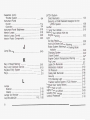
Seats and Restraint Systems ...........................
1-1
Front
Seats
...............................................
1-2
1-6
Safety Belts ..............................................
.......................................
1-24
Child Restraints
Supplemental Inflatable Restraint (SIR) ........ 1-43
............................
1-52
Restraint
System
Check
2-1
Features and Controls .....................................
2-3
Keys ........................................................
.......................................
2-8
Doors
and
Locks
Windows ................................................. 2-14
............................
2-18
Theft-DeterrentSystems
........... 2-22
Starting and Operating Your Vehicle
Mirrors .................................................... 2-35
Onstar@ .................................................. 2-40
.............................
2-42
HomeLink@
Transmitter
.........................................
2-46
Storage
Areas
..................................................
2-48
Sunroof
2-49
Vehicle Personalization .............................
Instrument Panel .............................................
3-1
InstrumentPanelOverview
..........................
3-4
......................................
3-25
Climate Controls
WarningLights,Gagesand
Indicators ......... 3-34
.................. 3-43
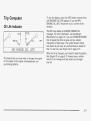
Driver iniormaiion Center @IC)
Trip Computer
.........................................
3-71
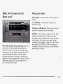
Audio
System(s)
.......................................
3-72
1-
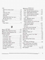
Driving Your Vehicle .......................................
4-1
..... 4-2
Your Driving. the Road.andYour
Vehicle
Towing
...................................................
4-30
Service and Appearance Care ..........................
5-1
5-3
Service .....................................................
.........................................................
5-5
Fuel
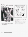
Checking Things Under the Hood
............... 5-12
Headlamp
Aiming
.....................................
5-50
....................................
5-55
Bulb Replacement
Windshield Wiper Blade Replacement
......... 5-62
......................................................
5-63
Tires
.....................................
5-84
Appearance
Care
5-91
Vehicle Identification .................................
5-92
Electrical System ......................................
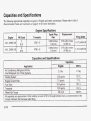
Capacities and Specifications ................... 5-100
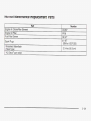
NormalMaintenanceReplacement
Parts
.... 5-101
Maintenance Schedule ....................... :............. 6-1
............ .................... 6-2
Maintenance
Schedule
Customer Assistance lnformation ....................
7-1
Customer Assistance lnformation .................. 7-2
Index ................................................................
1
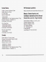
Canadian Owners
You can obtain a French copy of this manual from your
dealer or from:
Helm, Incorporated
P.O. Box 07130
Detroit, MI 48207
GENERAL MOTORS, GM, the GM Emblem, CADILLAC,
the CADILLAC Crest & Wreath and the name SEVILLE
are registered trademarks of General Motors
Corporation.
This manual includes the latest information at the time it
was printed. We reserve the right to make changes
after that time without further notice. For vehicles first
sold in Canada, substitute the name ”General Motors of
Canada Limited” for Cadillac Motor Car Division
whenever it appears in this manual.
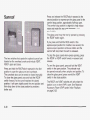
Please keep this manual in your vehicle, so it will be
there if you ever need it when you’re on the road. If you
sell the vehicle, please leave this manual in it so the
new owner can use it.
Litho in U.S.A.
Part No. 25739763 A First Edition
II
How to Use This Manual
Many people read their owner’s manual from beginning
to end when they first receive their new vehicle. If
you do this, it will help you learn about the features and
controls for your vehicle. In this manual, you’ll find
that pictures and words work together to explain things.
Index
A good place to look for what you need is the Index in
back of the manual. It’s an alphabetical list of what’s
in the manual, and the page number where you’ll find it.
@Copyright General Motors Corporation 06/19/02
All Rights Reserved
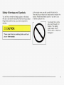
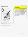
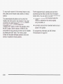
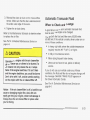
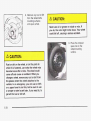
Safety Warnings and Symbols
You will find a number of safety cautions in this book.
We use a box and the word CAUTION to tell you about
things that could hurt you if you were to ignore the
warning.
These mean there is something that could hurt
you or other people.
In the caution area, we tell you what the hazard is.
Then we tell you what to do to help avoid or reduce the
hazard. Please read these cautions. If you don’t, you
or others could be hurt.
I
I
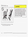
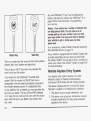
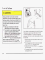
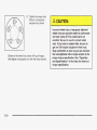
You will also find a circle
with a slash through it in
this book. This safety
symbol means “Don’t,’’
“Don’t do this” or “Don’t let
this happen.”
...
Ill
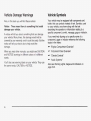
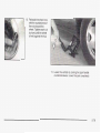
Vehicle Damage Warnings
Vehicle Symbols
Also, in this book you will find these notices:
Your vehicle may be equipped with components and
labels that use symbols instead of text. Symbols, used
on your vehicle, are shown along with the text
describing the operation or information relating to a
specific component, control, message, gage or indicator.
Notice: These mean there is something that could
damage your vehicle.
A notice will tell you about something that can damage
your vehicle. Many times, this damage would not be
covered by your warranty, and it could be costly. But the
notice will tell you what to do to help avoid the
damage.
When you read other manuals, you might see CAUTION
and NOTICE warnings in different colors or in different
words.
You’ll also see warning labels on your vehicle. They use
the same words, CAUTION or NOTICE.
iv
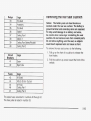
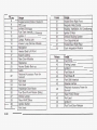
If you need help figuring out a specific name of a
component, gage or indicator reference the following
topics in the Index:
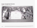
“EngineCompartmentOverview”
“InstrumentPanelOverview”
“ClimateControls”
“AudioSystems”
Also see Warning Lights, Gages and Indicators on
page 3-34.
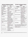
These are some examples of vehicle symbols you may find on your vehicle:
CAUTION
POSSIBLE
INJURY
A
LATCH BOTH LAP AND
SHOULDER BELTSTO
PROTECT
OCCUPANT
DO NOTTWISTSAFETY
BELT WHENAlTACHlNG
PROTECT
EYES BY
SHIELDING
CAUSTIC
BAlTERY
4CID COULD
CAUSE
BURNS
48:@
e-
- ,
LIGHTING
MASTER
SWITCH 0
TURN
SIGNALS
FASTEN
SEAT
BELTS
&
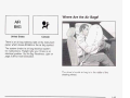
MOVE SEAT
FULLY
REARWARD*
SECURE
CHILD SEAT
\
\$!!
/
J
LAMPS
DO NOT INSTALL
A REAR-FACING
CHILD RESTRAINT
IN THIS SEATING
POSITION
Pf
BAlTERY
CHARGING
SYSTEM
1
COOLANT
PULL BELT
AVOID
SPARKS OR
FLAMES
SPARK OR
FLAME
COULD
EXPLODE
BAlTERY
1
COMPLETELY
rHEN SECURE
CHILD SEAT
1' 11'
1
DO NOT INSTALLA
FORWARD-FACING
CHILD RESTRAINT
IN THIS SEATING
POSITION
nnm IIXK
UNLOCK
DAYTIME
RUNNING
LAMPS
M
1
LAMPS
-Fb
-
ENGINE
COOLANT
TEMP
{{io
d
ENGINE OIL
PRESSUREW
n
=I;v
b
OWNER'S
MANUAL
a
SERVICE
SERVICE
MANUAL
a
V
5.
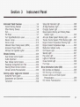
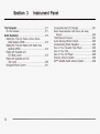
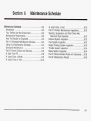
Section 1
Seats and Restraint Systems
Front Seats ..................................................... .l -2
Power Seats .................................................. 1.2
Power Lumbar ............................................... 1-2
Heated Seats ................................................. 1.3
Reclining Seatbacks ........................................ 1-3
Head Restraints ............................................. 1-5
Safety Belts ..................................................... 1-6
.................1-6
Safety Belts: They Are for Everyone
Questions and Answers About Safety Belts ......1-10
How to Wear Safety Belts Properly .................1-11
Driver Position .............................................. 1-11
Safety Belt Use During Pregnancy ..................1-18
Right Front Passenger Position ....................... 1-19
Rear Seat Passengers .................................. 1-19
Safety Belt Pretensioners ............................... 1-23
Safety Belt Extender .....................................
1-23
Child Restraints ............................................. 1-24
Older Children ............................................. -1-24
iniants
Young ana
Cniiaren ............................ 1-26
Child Restraint Systems ................................. 1-30
Where to Put the Restraint ............................. 1-33
..
Top Strap .................................................... 1.33
Top Strap Anchor Location ............................. 1.34
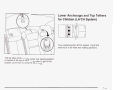
Lower Anchorages and Top Tethers for
-1-35
Children (LATCH System) ..........................
Securing a Child Restraint Designed for the
LATCH System ......................................... 1-38
Securing a Child Restraint in a Rear Seat
Position ................................................... 1-38
Securing a Child Restraint in the Right Front
1.40
Seat Position ............................................
Supplemental Inflatable Restraint (SIR) ............1.43
Where Are the Air Bags? ............................... 1-45
When Should an Air Bag Inflate? ....................
1-47
What Makes an Air Bag Inflate? ..................... 1-48
How Does an Air Bag Restrain? ..................... 1-48
What Will You See After an Air Bag Inflates? ...1-49
Servicing Your Air Bag-Equipped Vehicle .........1.51
Restraint System Check .................................. 1.52
__
Checking ‘Your Restraint Systems ...................1-32
Replacing Restraint System Parts
After a Crash ........................
, .....1-52
1-1
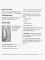
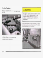
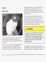
Front Seats
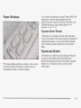
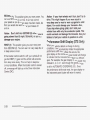
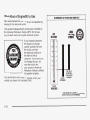
Power Lumbar
Power Seats
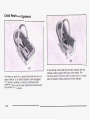
The power seat controls
are located on the
outboard sides of the front
seat cushions.
If your vehicle has this
feature, the control is
located on the outboard
sides of the front seats.
Use the power seat controls first to get the proper
position, then continue with the lumbar adjustment.
Move the front of the seat control up or down to
adjust the front portion of the cushion.
Move the rear of the seat control up or down to
adjust the rear portion of the cushion.
Lift up or push down on the center of the seat
control to move the entire seat up or down.
Slide the seat control forward or rearward to move
the seat forward or rearward.
1-2
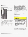
Press the lumbar control forward to increase support
and rearward to decrease support. Press the control up
or down to raise or lower the support mechanism.
Keep in mind that as your seating position changes, as
it may during long trips, so should the position of
your lumbar support. Adjust the seat as needed.
Reclining Seatbacks
The heated seats can only be used when the ignition is
rurnea on. Tne nearing eiemenrs in rne seais
automatically turn off when the vehicle's ignition is
turned off.
See Head Restraints on pape 1-5.
Only the outboard rear seat positions have heating
elements.
1-3
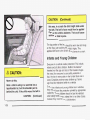
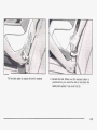
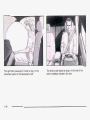
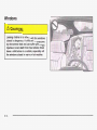
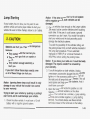
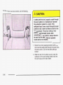
Sitting in a reclined position when your vehicle
is in motion can be dangerous. Even if you
buckle up, your safety belts can’t do their job
when you’re reclined like this.
The shoulder belt can’t do its job. In a crash,
you could go intoit, receiving neck or other
injuries.
The lap belt can’t do its job either. In a crash
the belt could go up over your abdomen. The
belt forces would be there, not at your pelvic
bones. This could cause serious internal
injuries.
Don’t have a seatback reclined if your vehicle is moving.
1-4
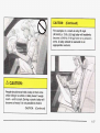
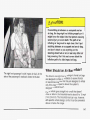
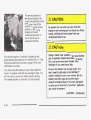
For proper protection when the vehicle is in
motion, have the seatback upright.Then sit
well back in theseat and wear your safety belt
properly.
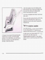
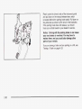
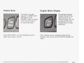
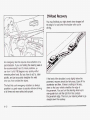
The switches used to
adjust the front head
restraints are located on
the outboard side of
each front seat.
Adjust your head restraint so that the top of the restraint
is closest to the top of your head. This position
reduces the chance of a neck injury in a crash.
Use the vertical power seat switch to move a front seat
head restraint up or down. Pull up or push down on
the switch to move the head restraint up or down.
Moving the head restraint also changes the height of
the shoulder belt.
The head restraints tilt forward and rearward also.
To tilt the head restraints forward, grasp the top of the
restraint and move it forward to where you want it
to go until you hear a click. It will then be locked into
that position until you need to move it again. Pulling
forward past the last position will allow the restraint to
return to an upright position.
The rear head restraints are adjustable, also. They tilt
-“A
IUI ( J ~ u
I a
1 ,el I ea1 v ~ aAr u1.1
lirte the h i i t h e ~ diestiaints,
but they do not move up and down.
-_
Cmn-.
-
1-5
Safety Belts
Safety Belts: They Are for Everyone
This part of the manual tells you how to use safety
belts properly. It also tells you some things you should
not do with safntnfbelts.
L d t let ar,+ne rib= where he or she can’t
wear a safety belt properly. If you are in a
crash and you’re not wearing a safety belt,
your injuries can be much worse. You canhit
things inside the vehicle or be ejected from
it.
You can be seriously injured or killed.In the
same crash, you might not be, if you are
buckled up. Always fasten your safety belt,
and check that your passengers’ belts are
fastened properly too.
1-6
It is extremely dangerous to ride in a cargo
area, inside or outside of a vehicle. In a
collision, people riding in theseareas are more
likely to be seriously injured or killed.Do not
allow people to ride in anyarea of your vehicle
that is not equipped with seats and safety
belts. Be sure everyone in your vehicle is in a
seat and using a safety belt properly.
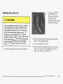
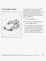
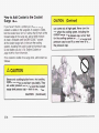
Your vehicle
has a fight
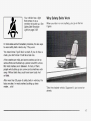
WhySafety Belts Work
that comes on as a
reminder to buckle UP. See When you ride
in or on anything, you go as fast as
Safety
Belt
Reminder
it goes.
Light on page 3-38.
matter... a lot!
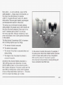
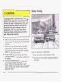
Take the simplest vehicle. Suppose it’s just a seat on
wheels.
1-7
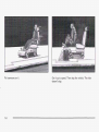
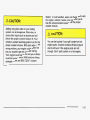
Put someone on it.
1-8
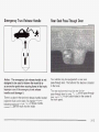
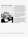
Get it up to speed. Then stop the vehicle. The rider
doesn’t stop.
6- C
Questions and Answers About
Safety Belts
Q: Won’t I be trapped in the vehicle after an
accident if I’m wearing a safety belt?
A: You could be - whether you’re wearing a safety
belt or not. But you can unbuckle a safety belt,
even if you’re upside down. And your chance
of being conscious during and after an accident, so
you can unbuckle and get out, is much greater if
you are belted.
Q: If my vehicle has air bags, why should I have to
wear safety belts?
A: Air bags are in many vehicles today and will be
or the safety belts!
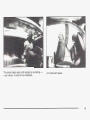
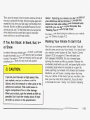
With safety belts, you slow down as the vehicle does.
You get more time to stop. You stop over more distance,
and your strongest bones take the forces. That’s why
safety belts make such good sense.
1-10
in
most of them in the future. But they are
supplemental systems only; so they work with
safety belts - not instead of them. Every air bag
system ever offered for sale has required the use of
safety belts. Even if you’re in a vehicle that has
air bags, you still have to buckle up to get the most
protection. That’s true not only in frontal collisions,
but especially in side and other collisions.
Q:
i’m a good driver, and i never drive far from
home, why should I wear safety belts?
A: You may be an
excellent driver, but if you’re in an
accident - even one that isn’t your fault - you and
your passengers can be hurt. Being a good
driver doesn’t protect you from things beyond your
control, such as bad drivers.
Most accidents occur within 25 miles (40 km) of
home. And the greatest number of serious injuries
and deaths occur at speeds of less than 40 mph
(65 km/h).
Safety belts are for everyone.
This part is only for people of adult size.
Be aware that there are special things to know about
safety belts and children. And there are different
rules for smaller children and babies. If a child will
be riding in your vehicle, see Older Children on
page 1-24 or Infants and Young Children on
page 1-26. Follow those rules for everyone’s protection.
First, you’ll want to know which restraint systems
your vehicle has.
We’ll start with the driver position.
Driver Position
This part describes the driver’s restraint system.
1-11
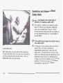
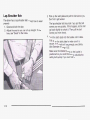
Lap-Shoulder Belt
The driver has a lap-shoulder belt. Here’s how to wear it
properly.
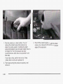
1. Close and lock the door.
2. Adjust the seat so you can sit up straight. To see
how, see “Seats” in the Index.
3. Pick up the latch plate and pull the belt across you.
Don’t let it get twisted.
The lap-shoulder belt may lock if you pull the belt
across you very quickly. If this happens, let the belt
go back slightly to unlock it. Then pull the belt
across you more slowly.
4. Push the latch plate into the buckle until it clicks.
Pull up on the latch plate to make sure it is
secure. If the belt isn’t long enough, see Safety
Belt Extender on page 1-23.
Make sure the release button on the buckle is
positioned so you would be able to unbuckle the
safety belt quickly if you ever had to.
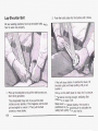
1-12
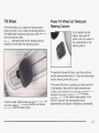
TIL
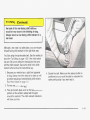
ne iap pari of the beit snouia be worn low and snug on
the hips, just touching the thighs. In a crash, this
applies force to the strong pelvic bones. And you'd be
less likely to slide under the lap belt. If you slid under it,
the belt would apply force at your abdomen. This
could cause serious or even fatal injuries. The shoulder
belt should go over the shoulder and across the
chest. These parts of the body are best able to take belt
restraining forces.
The safety belt locks if there's a sudden stop or crash,
or if you pull the belt very quickly out of the retractor.
~
I
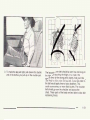
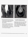
Shoulder Belt Height Adjuster
Before you begin to drive, move the shoulder belt
adjuster to the height that's right for you. Adjust the
height so that the shoulder portion of the belt is centered
on your shoulder. The belt should be away from your
face and neck, but not falling off your shoulder.
To adjust the front seat shoulder belts, see Head
Restraints on page 1-5.
1-13
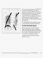
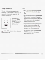
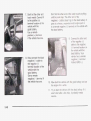
Q: What’s wrong with this?
You can be seriously hurt if your shoulder belt
is too loose. In a crash, you would move
forward too much, which could increase injury.
The shoulder belt should fit against your body.
A: The shoulder belt is too loose. It won’t give nearly
as much protection this way.
1-14
Q: What’s wrong with this?
6
You can be seriously injured if your belt is
buckled in the wrong place like this. In a crash,
the belt would go up over your abdomen. The
belt forces would be there, not at the pelvic
bones. This could cause serious internal
injuries. Always buckle your belt into the
buckle nearest you.
1-15
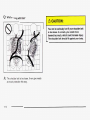
Q: What’s wrong with this?
’i
A: The shoulder belt is worn under the arm.
be worn over the shoulder at all times.
1-16
It should
You
le ser
sly injul I if - u wear the
shoulder belt under your arm. In a crash, your
body would move toofar forward, which would
increase the chance of head and neck injury.
Also, the belt would apply too much force to
the ribs, which aren’t as strong as shoulder
bones. YOU could also severely injure internal
organs like your liver or spleen.
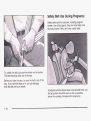
Safety Belt Use During Pregnancy
Safety belts work for everyone, including pregnant
women. Like all occupants, they are more likely to be
seriously injured if they don’t wear safety belts.
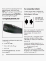
To unlatch the belt, just push the button on the buckle.
The belt should go back out of the way.
Before you close the door, be sure the belt is out of the
way. If you slam the door on it, you can damage
both the belt and your vehicle.
A pregnant woman should wear a lap-shoulder belt, and
the lap portion should be worn as low as possible,
below the rounding, throughout the pregnancy.
1-18
The best way to protect, the fetus is to protect the
mother. When a safety belt is worn properly, it’s more
likely that the fetus won’t be hurt in a crash. For
pregnant women, as for anyone, the key to making
safety belts effective is wearing them properly.
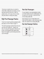
Right Front Passenger Position
To learn how to wear the right front passenger’s safety
belt properly, see Driver Position on page 1-1 1.
Rear Seat Passengers
It’s very important for rear seat passengers to buckle
up! Accident statistics show that unbelted people in the
rear seat are hurt more often in crashes than those
who are wearing safety belts.
Rear passengers who aren’t safety belted can be
thrown out of the vehicle in a crash. And they can strike
others in the vehicle who are wearing safety belts.
Rear Seat Passenger Positions
The right front passenger’s safety belt works the same
way as the driver’s safety belt - except for one
thing. If you ever pull the lap portion of the belt out all
the way, you will engage the child restraint locking
feature. If this happens, just let the belt go back all the
way and start again.
1-19
Lap-§boulder Belt
2. Push the latch plate into the buckle until it clicks.
All rear seating positions have lap-shoulder belts. Here’s
how to wear one properly.
1. Pick up the latch plate and pull the belt across you.
Don’t let it get twisted.
The shoulder belt may lock if you pull the belt
across you very quickly. If this happens, let the belt
go back slightly to unlock it. Then pull the belt
across you more slowly.
1-20
If the belt stops before it reaches the buckle, tilt
the latch plate and keep pulling until you can
buckle it.
Pull up on the latch plate to make sure it is secure.
If the belt is not long enough, see Safety Belt
Extender on page 1-23.
Make sure the release button on the buckle is
positioned so you would be able to unbuckle the
safety belt quickly if you ever had to.
3. To make the lap part tight, pull down on the buckle
end of the belt as you pull up on the shoulder part.
The lap part of the belt should be worn low and snug on
the hips, just touching the thighs. In a crash, this
applies force to the strong pelvic bones. And you’d be
~ Z S St i ~ t~
y siide wider iile iap beii. if you siia unaer if
the belt would apply force at your abdomen. This
could cause serious or even fatal injuries. The shoulder
belt should go over the shoulder and across the
chest. These parts of the body are best able to take belt
restraining forces.
1-21
The safety belt locks if there's a sudden stop or a crash,
or if you pull the belt very qu'-'-lv out of the retractor.
u can be seriously hurt if your shoulder belt
is too loose. In a crash, you would move
forward too much, which could increase injury.
The shoulder belt should fit against your body.
To unlatch the belt, just push the button on the buckle.
1-22
€2- c
Child Restraints
Older Children
Q: What is the proper way to wear safety belts?
A: If possible, an older child should wear a
lap-shoulder belt and get the additional restraint a
shoulder belt can provide. The shoulder belt
should not cross the face or neck. The lap belt
should fit snugly below the hips, just touching the
top of the thighs. It should never be worn over
the abdomen, which could cause severe or even
fatal internal injuries in a crash.
Accident statistics show that children are safer if they
are restrained in the rear seat.
In a crash, children who are not buckled up can strike
other people who are buckled up, or can be thrown
out of the vehicle. Older children need to use safety
belts properly.
Older children who have outgrown booster seats should
wear the vehicle’s safety belts.
1-24
nv:
What If a child is wearing a lap-shoulder belt,
.___
but the child is so small that the shoulder belt
is very close to the child’s face or neck?
A:
If the child is sitting in a seat next to a window,
move the child toward the center of the vehicle.
If the child is sitting in the center rear seat
passenger position, move the child toward the
safety belt buckle. In either case, be sure that the
shoulder belt still is on the child’s shoulder, so
that in a crash the child’s upper body would have
the restraint that belts provide.
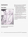
Never do this.
Here two children are wearing the same belt.
The belt can’t properly spread the impact
forces. In a crash, the two children can be
crushed together and seriously injured. A be!t
must be used by only one person
at a time.
1-25
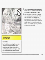
this way, in a crash the child might slide under
the belt. The belt’s force would then be applied
right on the child’sabdomen. That could cause
serious or fatal injuries.
The lap portion of the belt should be worn low and snug
on the hips, just touching the child’s thighs. This
applies belt force to the child’s pelvic bones in a crash.
Infants and Young Children
I
Here a child is sitting in a seat that has a
lap-shoulder belt, but the shoulder part is
behind the child. If the child wears the beltin
CAUTION: (Continued)
1-26
I
Everyone in a vehicle needs protection! This includes
infants and all other children. Neither the distance
traveled nor the age and size of the traveler changes
the need, for everyone to use safety restraints. In
fact, the law in every state in the United States and in
every Canadian province says children up to some
age
restrained while in avehicle.
- mustbe
Every time infants and young children ride in vehicles,
they should have the protection provided by appropriate
restraints. Young children should not use the vehicle’s
adult safety belts alone, unless there is no other choice.
Instead, they need to use a child restraint.
For example, in a crash at only 25 I bh
(40 km/h), a 12-lb. (5.5 kg) baby will suddenly
become a 240-lb. (1 18 kg) fsree om 8 person’s
arms. A baby should be secured in an
appropriate restraint.
People should never hold a baby in their arms
while riding in a vehicle.
A baby doesn’t weigh
much -- until a crash. During a crash a baby will
become so heavy it is not possible to hold
it.
CAUTION: (Continued)
I
1-27
Q: What are the different types of add-on child
restraints?
A: Add-on child restraints, whichare purchased by the
Children who are up against, or very close
to,
any air bag when it inflates can be seriously
injured or killed. Air bags plus lap-shoulder
belts offer outstanding protection for adults
and older children, but not for young children
and infants. Neither the vehicle’s safety belt
system nor its air bag system is designed for
them. Young children and infants need the
protection that a child restraint system can
provide.
1-28
vehicle’s owner, are available in four basic types.
Selection of a particular restraint should take into
consideration not onlythe child’s weight, height and
age but also whether or notthe restraint will be
compatible with the motorvehicle in which it will
be used.
For most basic types of child restraints, there are
many different models available. When purchasinga
child restraint, be sure it is designed to be used
in a motor vehicle. If it is, the restraint will have a
label saying that it meets federal motor vehicle
safety standards.
The restraint manufacturer’s instructions that come
with the restraint state the weight and height
limitations for a particular child restraint. In addition,
there are many kinds of restraints available for
children with special needs.
Newbc inl-.. .ts need complete support,
including support for the head and neck. is
This
necessary becausea newborn infant’s neck is
weak and its head weighs so much compared
with the restof its body. In a crash,
an infant ina
rear-facing seat settles into the restraint,
so the
crash forcescan be distributed across the
strongest partof an infant’s body, the back and
shoulders. Infants always should
be secured in
appropriate infant restraints.
~
~
~
The bL,y s..~cture of a young child is quite
unlike that of an adult or older child, for whom
the safety belts are designed. A young child’s
hip bones are still so small that the vehicle’s
regular safety belt may not remain low on the
hip bones, as it should. Instead, it may settle
up around the child’s abdomen. Ina crash, the
belt would apply force on a body
area that’s
unprotected by any bony structure. This alone
could cause serious or fatal injuries. Young
children always should be secured in
appropriate child restraints.
1-29
1-30
f
A forward-facing child seat (C-E) provides restraint for
the child’s body with theharness and also sometimes
with surfaces such as T-shaped or shelf-like shields.
A booster seat (F-G) is a child restraint designed to
improve the fit of the vehicle’s safety belt system. Some
booster seats have a shoulder belt positioner, and
5Oi7-16 hiyh-b~&b u u ~ seais
k ~ i lave a h e - p h i ilarness.
A booster seat can also help a child to see out the
window.
1-31
Q: How do child restraints work?
A: A child restraint system is any device designed for
use in a motor vehicle to restrain, seat, or position
children. A built-in child restraint system is a
permanent part of the motor vehicle. An add-on
child restraint system is a portable one, which
is purchased by the vehicle’s owner.
For many years, add-on child restraints have used
the adult belt system in the vehicle. To help
reduce the chance of injury, the child also has to be
secured within the restraint. The vehicle’s belt
system secures the add-on child restraint in the
vehicle, and the add-on child restraint’s harness
system holds the child in place within the restraint.
One system, the three-point harness, has straps
that come down over each of the infant’s shoulders
and buckle together at the crotch. The five-point
harness system has two shoulder straps, two
hip straps and a crotch strap. A shield may take the
place of hip straps. A T-shaped shield has
shoulder straps that are attached to a flat pad which
rests low against the child’s body. A shelf- or
armrest-type shield has straps that are attached to
a wide, shelf-like shield that swings up or to
the side.
1-32
When choosing a child restraint, be sure the child
restraint is designed to be used in a vehicle. If it is, it
will have a label saying that it meets federal motor
vehicle safety standards.
Then follow the instructions for the restraint. You may
find these instructions on the restraint itself or in a
booklet, or both. These restraints use the belt system in
your vehicle, but the child also has to be secured
within the restraint to help reduce the chance of personal
injury. When securing an add-on child restraint, refer
to the instructions that come withthe restraint which may
be on the restraint itself or in a booklet, or both, and
to this manual. The child restraint instructions are
important, so if they are not available, obtain a
replacement copy from the manufacturer.
Wherever you insta!! it, be w:e to secure the child
restraint properly.
Accident statistics show that children are safer if they
are restrained in the rear rather than the front seat.
General Motors, therefore, recommends thatchild
restraints be secured in a rear seat, including an infant
riding in a rear-facing infant seat, a child riding in a
forward-facing child seat and an older child riding in a
booster seat. Never put a rear-facing child restraint
in the front passenger seat. Here’s why:
A cl A in a rear-:.,,ing
cl 1 restraint can be
seriously injured or killed if the right front
passenger’s air bag inflates. This is because
the back of the rear-facing child restraint
would be very close to the inflating airbag.
Always secure a rear-facing child restraint in a
rear seat.
You may secure a forward-facing child
restraint in the right front seat, but before you
do, always move the front passenger seatas
far back as it will go. It’s better to secure the
child restraint in a rear seat.
Keep in mind that an unsecured child restraint can
move around in a collision or sudden stop and injure
people in the vehicle. Be sure to properly secure
any child restraint in your vehicle - even when no child
is in it.
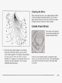
Top Strap
Some child restraints have a top strap, or “top tether”. It
can help restrain the child restraint during a collision.
For it to work, a top strap must be properly anchored to
the vehicle. Some top strap-equipped child restraints
are designed for use with or without the top strap being
anchored. Others require the top strap always to be
anchored. Be sure to read and follow the instructions for
your child restraint. If yours requires that the top strap
be anchored, don’t use the restraint unless it is anchored
properly.
If the child restraint does not have a top strap, one can
be obtained, in kit form, for many child restraints.
Ask the child restraint manufacturer whether or not a kit
is available.
1-33
Anchor the top strap to one of the following anchor
points. Be sure to use an anchor point located on the
same side of the vehicle as the seating position
where the child restraint will be placed.
If you have an adjustable head restraint, route the top
strap under it.
Once you have the top strap anchored, you’ll be ready
to secure the child restraint itself. Tighten the top
strap when and as the child restraint manufacturer’s
instructions say.
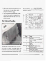
Top Strap Anchor Location
Your vehicle has top strap anchors already installed for
the rear seating positions. You’ll find the two rear
outboard anchors behind the rear seat on the filler panel.
In Canada, the law requires that forward-facing child
restraints have a top strap, and that the strap be
anchored. In the United States, some child restraints
also have a top strap. If your child restraint has a
top strap, it should be anchored.
1-34
In order to get to one of these brackets, you’ll have to
open the trim cover. When using a top
strapped-equipped child restraint in a rear outboard
position, be sure to route the top strap under the head
restraint.
r
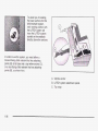
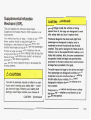
To assist you in locating
the lower anchors for this
child restraint system,
each seating position with
the LATCH system will
have the LATCH system
symbol on the seatback
directly above the anchors.
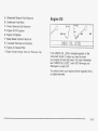
In order to use the system, you need either a
forward-facing child restraint that has attaching
points (B) at its base and a top tether anchor (C),
or a rear-facing child restraint that has attaching
points (B), as shown here.
A.Vehicleanchor
B. LATCH system attachment points
C. Top strap
1-36
__
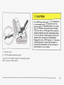
If a -AT(
pe
ch
restrain
sn’t attal
to
its anchorage points, the restraint won’t be
able to protect a child sitting there.In a crash,
the child could be seriously injured or killed.
Make sure that a LATCH-type child restraint is
properly installed using the anchorage points,
or use the vehicle’s safety belts to secure the
restraint. See “Securing a Child Restraint
Designed for the LATCH System” or “Securing
a Child Restraint in a Rear Seat Position’’ in
the Index for informationon how to secure a
child restraint in your vehicle.
A. Vehicle anchor
B. LATCH system attachment points
Use the LATCH system instead of the vehicle’s safety
belts to secure a child restraint.
1-37
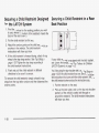
Securing a Child Restraint Designed
for the LATCH System
Securing a Child Restraint in a Rear
Seat Position
1. Find the anchors for the seating position you want
to use, where the bottom of the seatback meets the
back of the seat cushion.
2. Put the child restraint on the seat.
3. Attach the anchor points on the child restraint to the
anchors in the vehicle. The child restraint
instructions will show you how.
4. If the child restraint is forward-facing, attach the top
strap to the top strap anchor. See Top Strap on
page 1-33. Tighten the top strap according to
the child restraint instructions.
5. Push and pull the child restraint in different
directions to be sure it is secure.
To remove the child restraint, simply unhook the top
strap from the top tether anchor and then disconnect the
anchor points.
If your child restraint is equipped with the latch system,
see Lower Anchorages and Top Tethers for Children
(LATCH System) on page 1-35.
You’ll be using the lap-shoulder belt. See TopStrap on
page 1-33 if the child restraint has one. Be sure to follow
the instructions that came with thechild restraint. Secure
the child restraint when and as the instructions say.
1. Put the restraint on the seat.
2. Pick up the latch plate, and run the lap and shoulder
portions of the vehicle’s safety belt through or
around the restraint. The child restraint instructions
will show you how.
1-38
Tilt the latch plate to adjust the belt if needed.
3. Buckle the belt. Make sure the release button is
positioned so you would be able to unbuckle the
safety belt quickly if you ever had to.
1-39
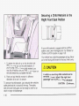
Securing a Child Restraint in the
Right Front Seat Position
If your child restraint is equipped with the LATCH
system, see Lower Anchorages and Top Tethers for
Children (LATCH System) on page 1-35.
Your vehicle has a rightfront passenger air bag. Never
put a rearfacing child restraint in this seat. Here’s why:
4. To tighten the belt, pull up on the shoulder belt
while you push down on the child restraint. If
you’re using a forward-facing child restraint, you
may find it helpful to use your knee to push down on
the child restraint as you tighten the belt.
5. Push and pull the child restraint in different
directions to be sure it is secure.
To remove the child restraint, just unbuckle the vehicle’s
safety belt and let it go back all the way. The safety
belt will move freely again and be ready to work for an
adult or larger child passenger.
1-40
A child in a rear-facing child restraint can be
seriously injured or killed if the right front
passenger’s air bag inflates. This is because
CAUTION:
(Continued)
the back of the rear-fa_---achild restraint
would be very close to the inflating air bag.
Always secure a rear-facing child restraint in a
rear seat.
Although a rear seat is a safer place, you can secure a
forward-facing child restraint in the right front seat.
You'll be using the lap-shoulder belt. See the earlier part
about the Top Strap on page 1-33, if the child restraint
has one. Be sureto follow the instructions that came
with the child restraint. Secure the child in the child
restraint when and as the instructions say.
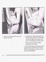
1. Because your vehicle has a right front passenger
air bag, always move the seat as far back as it will
go before securing a forward-facing child restraint.
see #??~fl/er.%2!S 2:: p3,"z ? 2.
4. Buckle the belt. Make sure the release button is
positioned so you would be able to unbuckle the
safety belt quickly if you ever had to.
2. Put the restraint on the seat.
3. Pick up the latch plate, and run the lap and shoulder
portions of the vehicle's safety belt through or
around the restraint. The child restraint instructions
will show you how.
1-41
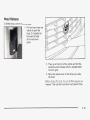
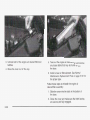
5. Pull the rest of the lap belt all the way out of the
retractor to set the lock.
1-42
6. To tighten the belt, feed the lap belt back into the
retractor while you push down on the child restraint.
You may find it helpful to use your knee to push
down on the child restraint as you tighten the belt.
7. Push and pull the child restraint in different
directions to be sure it is secure.
To remove the child restraint, just unbuckle the vehicle’s
safety belt and let it go back all the way. The safety
belt will move freely again and be ready to work for an
adult or larger child passenger.
This part explains the frontal and side impact
Supplemental Inflatable Restraint (SIR) systems or air
bag systems.
Your vehicle has four air bags - a frontal air bag for the
driver, another frontal air bag for the right front
passenger, a side impact air bag for the driver, and
another side impact air bag for the right front passenger.
Frontal air bags are designed to help reduce the risk
of injury from the force of an inflating frontal air bag. But
these air bags must inflate very quickly to do their job
and comply with federal regulations.
Here are the most important things to know about the
air bag systems:
’_
-an be severel, .njured or killed i n a crash
if you aren’t wearing your safety belt
- even if
you have air bags. Wearing your safety belt
during a crash helps reduce your chance of
CAUTION:
(Continued)
hitting things inside the vehicle or being
ejected from it. Air bags are designed to work
with safety belts but don’t replace them.
Frontal air bags for the driver and right front
passenger are designed to deploy only
in
moderate to severe frontal and near frontal
crashes. They aren’t designedto inflate at all
in
rollover, rear or low-speed frontal crashes, or
in
many side crashes.
And, for some unrestrained
occupants, frontal air bags may provide less
protection in frontal crashes than more forceful
air bags have provided in the past.
The side impact air bags for the driver and right
front passenger are designed to inflate only in
moderate to severe crashes where something
hits the side of your vehicle.
They aren’t
designed to inflatein frontal, in rollover orin
rear crashes.
Everyone in your vehicle shouldwear a safety
belt properly- whether or not there’s an air
bag for that person.
1-43
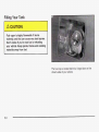
Both frontal and side impact air bags inflate
with great force, faster than the blink
of an eye.
If you’re too close to an inflatingbag,
airas you
would be if you were leaning forward,
it could
seriously injure you. Safety belts help keep you
in position for air bag inflation before and
during a crash. Always
wear your safety belt,
even with frontal air bags.
The driver should sit
as far back as possible while
still maintaining
control of the vehicle. Front occupants should
1-44
Anyone who is up against, or very ose to,
any air bag when it inflates can be seriously
injured or killed. Air bags plus lap-shoulder
belts offer the best protection for adults, but
not for young children and infants.Neither the
vehicle’s safety belt system nor its air bag
system is designed for them. Young children
and infants need the protection that a child
restraint system can provide. Always secure
children properly in your vehicle.
To read how,
see the part of this manual called“Older
Children” or “Infants and Young Children”.
L
aa
.
I
Q)
.CI
.C
v)
Q)
Q
w
G
.-C
3
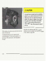
The right front passenger's frontal air bag is in the
instrument panel on the passenger's side.
1-46
The driver's side impact air bag is in the side of the
driver's seatback closest to the door.
If something is between an occupant and an
air bag, the bag might not inflate properly ~r it
might force the object into that person causing
severe injury or evendeath. The path of an
inflating air bag must be keptclear. Don’t put
anything between an occupant and an airbag,
and don’t attach or put anything on the
steering wheel hub or on or near any other air
bag covering. Don’t let seat covers block the
inflation path of a side impact air bag.
When Should an Air Bag Inflate?
The right front passenger’s side impact air bag is in the
side of the passenger’s seatback closest to the door.
The driver’s and right front passenger’s frontal air bags
are designed to inflate in moderate to severe frontal
or near-irontai crashes. But they are designed to inflate
only if the impact speed is above the system’s
designed “threshold level”.
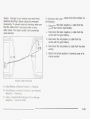
If your vehicle goes straight into a wall that doesn’t
move or deform, the threshold level is about 9 to 15 mph
(14 te 24 kmk). The threshold ledel c m vary., however,
with specific vehicle design, so that it can be somewhat
above or below this range.
1-47
If your vehicle strikes something that will move or
deform, such as a parked car, the threshold level will be
higher. The driver’s and right front passenger’s frontal
air bags are not designed to inflate in rollovers, rear
impacts, or in many side impacts because inflation
would not help the occupant.
The side impact air bags are designed to inflate in
moderate to severe side crashes. A side impact air bag
will inflate if the crash severity is above the system’s
designed “threshold level”. The threshold level can vary
with specific vehicle design. Side impact air bags are
not designed to inflate in frontal or near-frontal impacts,
rollovers or rear impacts, because inflation would not
help the occupant. A side impact air bag will only deploy
on the side of the vehicle that is struck.
In any particular crash, no one can say whether an air
bag should have inflated simply because of the damage
to a vehicle or because of what the repair costs were.
For frontal air bags, inflation is determined by the angle
of the impact and how quickly the vehicle slows down
in frontal and near-frontal impacts. For side impact
air bags, inflation is determined by the location
and severity of the impact.
1-48
What Makes an Air Bag Inflate?
In an impact of sufficient severity, the air bag sensing
system detects that the vehicle is in a crash. For
both frontal and side impact air bags, the sensing
system triggers a release of gas from the inflator, which
inflates the air bag. The inflator, the air bag and
related hardware are all part of the air bag modules
inside the steering wheel, the instrument panel, and the
side of the front seatbacks closest to the door.
How Does an Air Bag Restrain?
In moderate to severe frontal or near frontal collisions,
even belted occupants can contact the steering wheel
or
the instrument panel. In moderateto severe side
collisions, even belted occupants can contact the inside
of the vehicle. The air bag supplements the protection
provided by safety belts. Air bags distribute the force
of
the impact more evenly over the occupant’s upper body,
stopping the occupant more gradually. But the frontal air
bags wouldnot help you in many types of collisions,
including rollovers, rear impacts, and many side impacts,
primarily because an occupant’smotion is not toward the
air bag.Side impact air bags would not help you
in many
types of collisions, including frontal or near frontal
collisions, rollovers, and rear impacts, primarily because
an occupant’s motion is not toward those air bags.
Air bags shou!d never be regarded as anything more than
a supplementto safety belts, andthen only in moderate
to severe frontal or near-frontal collisions for the driver’s
and rightfront passenger’s frontal air bags, and only in
moderate to severe side collisions for the driver’s and
right frontpassenger’s side impact air bag.
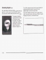
What Will You See After an Air Bag
Inflates?
After the air baginflates, it quickly deflates, so quickly that
some people may not even realize the air bag inflated.
Some components of the
air bag module-the steering
wheel hub for the driver’s
air bag, the instrument panel for
the rightfront passenger‘s bag,the side of the seatback
closest to the door for thedriver and right front
passenger’s side impact air bags- will be hot for a short
time. Theparts of the bag that come
into contact with you
may be warm,but not too hot to touch. There will be
some smoke anddust coming from the vents in the
deflated air bags. Air baginflation doesn’t prevent the
driver fromseeing or being able to steer thevehicle, nor
does it stop people from leaving the vehicle.
~
~
When an air bag inflates, there is dust in the
air. This dust c ~ u l dcause breathing problems
or other
for people with a history of asthma
breathing trouble. To avoid this, everyone in
the vehicle should getout as soon as it is safe
to do so. If you have breathing problems but
can’t get out of the vehicle after an air bag
inflates, then get fresh air by opening a
window or a door. If you experience breathing
problems following an air bag deployment, you
should seek medical attention.
Your vehicle has a feature that will automatically unlock
the doors and turn the interior lamps on when the air
bags inflate (if battery power is available). You can lock
the doors again and turn the interior lamps off by
using the door lock and interior lamp controls.
1-49
In many crashes severe enough to inflate an air bag,
windshields are broken by vehicle deformation.
Additional windshield breakage may also occur from the
right front passenger air bag.
0
Air bags are designed to inflate only once. After an
air bag inflates, you’ll need some new parts for
your air bag system. If you don’t get them, the air
bag system won’t be there to help protect you
in another crash. A new system will include air bag
modules and possibly other parts. The service
manual for your vehicle covers the need to replace
other parts.
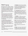
Your vehicle is equipped with a crash sensing and
diagnostic module, which records information
about the frontal air bag system. The module
records information about the readiness of the
system, when the system commands air bag
inflation and driver’s safety belt usage at
deployment. The module also records speed,
engine rpm, brake and throttle data.
1-50
0
Let only qualified technicians work on your air bag
systems. Improper service can mean that an air
bag system won’t work properly. See your dealer for
service.
Notice: If you damage the covering for the driver’s
or the right front passenger’s air
bag, or the air
bag covering on the driver’s and right front
passenger’s seatback, the bag may not work
properly. You may have to replace the air bag
module in the steering wheel, both the air bag
module and the instrument panel for the right front
passenger’s air bag, or both the air bag module
and seatback for the driver’s and right front
passenger’s side impact air bag. Do not open or
break the air bag coverings.
Air bags affect how your vehicle should be serviced.
There are parts of the air bag systems in several places
around your vehicle. Your dealer and the service
manual have information about servicing your vehicle
and the air bag systems. To purchase a service manual,
see Service Publications Ordering Information on
page 7-9.
For up to 10 seconds after the ignition key is
turned off and the battery is disconnected, an
air bag can still inflate during improper
service. You can be injuredif you are close to
an air bag when it inflates. Avoid yellow
connectors. They are probably part of the air
bag system. Be sure to follow proper service
procedures, and make sure the person
performing work for you is qualified to doso.
The air bag systems do not need regular maintenance.
1-51
Restraint System Check
Replacing Restraint System Parts
After a Crash
Checking Your Restraint Systems
Now and then, make sure the safety belt reminder light
and all your belts, buckles, latch plates, retractors
and anchorages are working properly. Look for any other
loose or damaged safety belt system parts. If you see
anything that might keep a safety belt system from doing
its job, have it repaired.
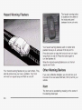
Torn or frayed safety belts may not protect you in a
crash. They can rip apart under impact forces. If a belt
is torn or frayed, get a new one right away.
Also look for any opened or broken air bag covers, and
have them repaired or replaced. (The air bag system
does not need regular maintenance.)
1-52
A crash can damage the restraint SI ems in
your vehicle. A damaged restraint system may
not properly protect the person usingit,
resulting in serious injury or even
death in a
crash. To help make sure your restraint
systems are working properly after a crash,
have them inspected and any necessary
replacements made as soon as possible.
If you’ve had a crash, do you need new belts or LATCH
system parts?
After a very minor collision, nothing may be necessary.
But if the belts were stretched, as they would be if
worn during a more severe crash, the you need
new parts.
If the LATCH system was being used during a more
severe crash, you may need new LATCH system parts.
If belts are cut or damaged, replace them. Collision
damage also may mean you will need to have LATCH
system, safety belt or seat parts repaired or replaced.
New pa?c 2nd repairs may be necessary even if the
belt or LATCH system wasn’t being used at the time of
the collision.
If an air bag inflates, you’ll need to replace air bag
system parts. See the part on the air bag system earlier
in this section.
If the frontal air bags inflate, you’ll also need to replace
the driver’s and right front passenger’s safety belt
buckle assembly. Be sure to do so. Then the new buckle
assembly will be there to help protect you in a collision.
1-53
Section 2
Features and Controls
Keys ............................................................... 2.3
Remote Keyless Entry System ......................... 2.4
Remote Keyless Entry System Operation ...........2.5
Doors and hocks ............................................. 2-8
Door Locks ...................................................
-2-8
Central Door Unlocking System ........................ 2-9
Power Door Locks .......................................... 2-9
Programmable Automatic Door Locks ................2-9
Rear Door Security Locks .............................. 2-10
Lockout Protection ........................................ 2-10
Leaving Your Vehicle .................................... 2-10
Trunk ..........................................................
2-11
Windows ........................................................
2.14
Power Windows ............................................ 2.15
Sun Visors ................................................... 2.17
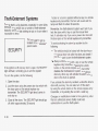
Theft-Deterrent Systems .................................. 2.18
PASS-Key@Ill .............................................. 2-20
PASS-Key@II I Operation ............................... 2-20
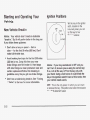
Starting and Operating Your Vehicle ................2.22
New Vehicle Break-In .................................... 2.22
Ignition Positions ..........................................
2-22
Starting Your Engine ..................................... 2.23
Engine Coolant Heater .................................. 2.24
Automatic Transaxle Operation ....................... 2.26
Parking Brake ............................................. 2-29
Shifting Into Park (P) ..................................... 2-31
Shifting Out of Park (P) ................................. 2-32
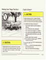
Parking Over Things That Burn .......................2-33
Engine Exhaust ............................................ 2-33
Running Your Engine While You Are Parked ....2-34
Mirrors ........................................................... 2-35
Automatic Dimming Rearview Mirror with
Onstar@................................................... 2-35
Automatic Dimming Rearview Mirror with
Onstar@and Compass ............................... 2-35
Outside Power Mirrors ................................... 2-37
Outside Automatic Dimming Mirror ..................2-38
Outside Curb View Assist Mirror ..................... 2-38
Outside Convex Mirror ................................... 2-39
Outside Heated Mirrors .................................. 2-39
OnStarG ......................................................... 2-40
Onstat-@ System ........................................... 2-40
HomeLink@ Transmitter................................... 2-42
Programming the HomeLink Transmitter ........... 2-42
2-1
Section 2
Features and Controls
Storage Areas ................................................ 2.46
Glove Box ................................................... 2-46
Cellular Telephone ........................................ 2-46
Center Console Storage Area ......................... 2-46
Map Pocket ................................................. 2-46
Assist Handles ............................................. 2-46
Garment
Hooks
................
. . . . . . . . . . . . . . . . .2-47
2-2
Umbrella Holder ....................................... 2-47
Floor Mats ............................................... 2-47
Convenience Net .......................................... 2-47
Sunroof ......................................................... 2-48
Vehicle Personalization ................................... 2-49
Memory Seat, Mirrors and Steering Wheel .......2-49
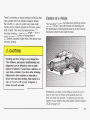
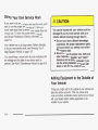
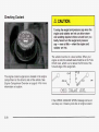
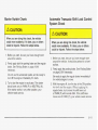
Leaving children in a vehicle with the ignition
key is dangerous for many reasons.A child or
others could be badly injured or even killed.
They could operate the power windowsor
other controls oreven make the vehicle move.
If they turned the ignition to ACC or ON and
moved the shift lever out ofPARK (P),that
would release the parking brake.
Don’t leave the keys in a vehicle with children.
2-3
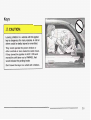
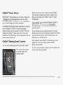
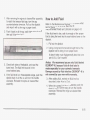
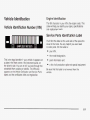
Any new PASS-Key@Ill key must be programmed
before it will start your vehicle. See PASS-Key@111 on
page 2-20 for more information on programming
your new key.
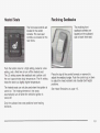
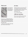
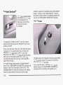
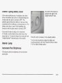
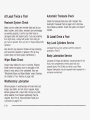
Master Key
‘I
Valet Key
There is a master key that works all of the lock cylinders
(driver’s door, trunk, ignition and glove box).
Notice: Your vehicle has a number of features that
can help prevent theft. You can have a lot of
trouble getting into your vehicle if you ever lock
your keys inside. You may even have to damage
your vehicle to get in. So be sure you have
spare keys.
In an emergency, contact Cadillac Roadside Assistance.
See Roadside Service on page 7-5.
If your vehicle is equipped with the Onstar@system with
an active subscription and you lock your keys inside
the vehicle, Onstar@may be able to send a command to
unlock your vehicle. See OnStaP System on page 2-40
for more information.
There is also a VALET key which only operates the
driver’s door and the ignition.
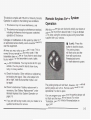
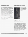
Remote Keyless Entry System
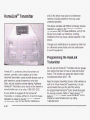
Your vehicle has the PASS-Key@Ill vehicle theft
system. Both the master and VALET key have a
transponder in the key head that matches a decoder in
the vehicle’s steering column. If a replacement key
or any additional key is needed, you must purchase this
key from your dealer. The key will have PK3 stamped
on it. Keep the bar code tag that came with the original
keys. Give this tag to your dealer if you need a new
key made.
Your keyless entry system operates on a radio
frequency subject to Federal Communications
Commission (FCC) Rules and with Industry Canada.
This device complies with Part 15 of the FCC Rules.
Operation is subject to the following two conditions:
1. This device may not cause interference, and
2. This device must accept any interference received,
including interference that may cause undesired
operation of the device.
2-4
This device complies with RSS-310 of Industry Canada
Operation is subject to the following two conditions:
1. This device may not cause interference, and
2. This device must accept any interference received,
including interference that may cause undesired
operation of the device.
Changes or modifications to this system by other than
an authorized service facility could void authorization to
use this equipment.
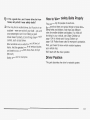
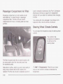
At times you may notice a decrease in range. This is
normal for any remote keyless entry system. If the
transmitter does not work or if you have to stand closer
to your vehicle for the transmitter to work, try this:
Check the distance. You may be too far from your
vehicle. You may need to stand closer during
rainy or snowy weather.
Check the location. Other vehicles or objects may
be blocking the signal. Take a few steps to the
left or right, hold the transmitter higher, and
try again.
Check to determine if battery replacement is
necessary. See “Battery Replacement” under
Remote Keyless Entry System Operation on
page 2-5.
If you are still having trouble, see your dealer or a
qualified technician for service.
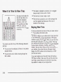
With this system you can lock and unlock your doors or
unlock your trunk from about 3 feet (1 m) up to 30 feet
(9 m) away using the remote keyless entry transmitter
supplied with your vehicle.
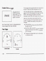
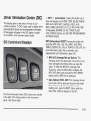
8 (Lock): Press this
button to lock the doors.
The parking lamps
will flash once and the
horn will sound once.
Pressing lock arms
the theft-deterrent system.
The parking lamps will not flash, however, if the manual
parking lamps are left on. Remote confirmation is not
operational if a door is open.
You can program your vehicle so the parking lamps will
Rot flash and the hori; Vfill iiot 30Ufid. For more
information, see DIG Vehicle Personalization on
page 3-60.
2-5
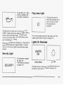
(Unlock): Press this button to unlock the driver’s
door. The parking lamps on your vehicle will flash twice.
The parking lamps will not flash if they have been
turned on manually. Remote confirmation is not
operational if a door is open.
Press this button again within one to five seconds to
unlock the other doors. It will also disarm the
theft-deterrent system and turn on the interior lamps at
night.
You can program your vehicle so the parking lamps will
not flash. For more information, see DIC Vehicle
Personalization on page 3-60.
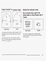
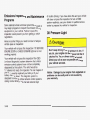
(Fuel Door): Press this button to open the fuel
door. The valet lockout switch must be in the OFF
position for this feature to work. See Valet Lockout
Switch under Theft-Deterrent Systems on page 2-78 for
more information.
(Trunk): Press this button to open the trunk. The
valet lockout switch must be in the OFF position for
this feature to work. See Valet Lockout Switch under
Theft-Deterrent Systems on page 2- 78 for more
information.
The remote keyless entry transmitter can be used to
recall the memory settings for up to two drivers.
For more information, see DIC Vehicle Personalization
on page 3-60 and Memory Seat, Mirrors and Steering
Wheel on page 2-49.
2-6
Matching Transmitter(s) to Your
Vehicle
Each remote keyless entry transmitter is coded to
prevent another transmitter from unlocking your vehicle.
If a transmitter is lost or stolen, a replacement can
be purchased through your dealer. Remember to bring
any remaining transmitters with you when you go to
your dealer. When the dealer matches the replacement
transmitter to your vehicle, any remaining transmitters
must also be matched. Once your dealer has coded the
new transmitter, the lost transmitter will not unlock
your vehicle. Each vehicle can have a maximum of four
transmitters matched to it.
Vehicles are delivered with two transmitters. See your
dealer for information on how to obtain additional
transmitters.
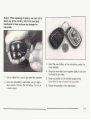
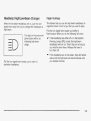
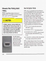
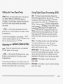
Battery Replacement
Under normal use, the battery in your remote keyless
entry transmitter should last about four years.
You can tell the battery is weak if the transmitter won’t
work at the normal range in any location. If you have
to get close to your vehicle before the transmitter works,
it’s probably time to change the battery.
Notice: When replacing the battery, use care not ta
touch any of the circuitry. Static from your body
transferred to these surfaces may damagethe
transmitter.
3. Insert the new battery as the instructions under the
cover indicate.
4. Snap the transmitter back together tightly to be sure
no moisture can enter.
1. Use an object like a coin to pry open the transmitter.
5. Press any button on the remote keyless entry
&._^-^.-:La..
. ~-.
.- .- ..
LI a
1 1 3 1 I IILLCI t~ I
ILI II V II I L LI
~le I I CII rsl-l-liiiel.
-1-
2. Once ine transmitter is separated, use an ObJeCt
like a pencil to remove the old battery. Do not use
a metal object.
!-
AI..
I
6. Check the operation of the transmitter.
2-7
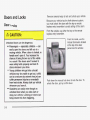
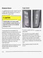
Doors and Locks
Door Locks
v
Unlocked doors can be dangerous.
Passengers - especially children - can
easily open the doors and fall outof a
moving vehicle. When a door is locked, the
handle won’t open it. You increase the
chance of being thrown outof the vehicle
in a crash if the doors aren’t locked.So,
wear safety belts properly and lock the
doors whenever you drive.
0 Young children who get into unlocked
vehicles may be unable to get out. A child
can be overcome by extreme heat and can
suffer permanent injuries or even death
from heat stroke. Always lock your vehicle
whenever you leave it.
Outsiders can easily enter through an
unlocked door when you slow down or
stop your vehicle. Locking your doors can
help prevent this from happening.
2-8
There are several ways to lock and unlock your vehicle.
Because your vehicle has the theft-deterrent system,
you must unlock the doors with the key or remote
keyless entry transmitter to avoid setting off the alarm
From the outside, use either the key or the remote
keyless entry transmitter.
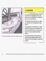
From the inside, use the
manual lock levers located
at the top of the door
panel near the window.
Push down the manual lock lever to lock the door. To
unlock the door, pull up on the lever.
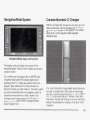
Central Door Unlocking System
Thn
n n t n r n r rlp.nr In-,
e * a e i t n h n c .
I I IG
yuvvGl
uuul Iubh 3vvIlbI
Yourvehicie has a centrai door unlocking mode and a
theft-deterrent system. When unlocking the driver’s door,
youcanunlocktheother
doors by holding the key in
the turned position for a few seconds or by quickly
turning the door
key
twice
in the lock
cylinder.
Programmable Automatic Boor
Power Door Locks
The power door lock
switches are located on
the door panels near
the windows.
Press the bottom part of the power door lock switch
located on either front door to lockall of the doors
at once. Press the top of the switch to unlock all of the
d a x s at m c e .
lubated on the rear doors
can also lock all the doors at once by pressing the
bottom part of them, but they cannot unlock the doors.
Innot
Locks
Your vehicle is programmed so that, when the doors are
closed, the ignition is on and the shift lever is moved
out of PARK (P), all the doors will lock. The doors
will unlock every time you stop the vehicle and move
the shift lever into PARK (P).
If someone needs to get out while your vehicle is not in
PARK (P), have the person use the manual lever or
power door lock switch. When the door is closed again,
it will not lock automatically. Use the manual lever or
power door lock switch to lock the door.
With the vehicle in PARK (P) and the ignition in ON, the
door locks can be programmed through prompts
dispiayed UII iile Eriver irliormaiion Cenier (EiCj. These
prompts allow the driver to choose various lock and
unlock settings. For programming information, see DIC
Vehicle Personalization on page 3-60.
2-9
Rear Door Security Locks
Your vehicle is equipped with rear door security locks
that prevent passengers from opening the rear doors on
your vehicle from the inside.
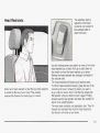
The rear door security
locks are located on the
inside edge of each
rear door. You must open
the doors to access
them.
1. Unlock the door using the remote keyless entry
transmitter, the front door power lock switch or
by lifting the rear door manual lock.
2. Then open the door from the outside.
To cancel the rear door security lock, do the following:
1. Unlock the door and open it from the outside.
2. Move the lever all the way down.
3. Do the same for the other rear door.
The rear door locks will now work normally.
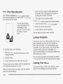
Lockout Protection
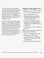
To use these locks, do the following:
1. Move the lever on the door all the way up to the
engaged position.
2. Close the door.
Leaving your key in any ignition position with any door
open will disable the power door lock switches as
well as the lock button on the remote keyless entry
transmitter. If you close the doors, you can lock them
using the remote keyless entry transmitter. It is
always recommended that you remove the ignition key
when locking your vehicle.
The anti-lockout feature can be overridden by holding
the power door lock switch for three seconds or longer.
3. Do the same thing to the other rear door lock.
The rear doors on your vehicle cannot be opened from
the inside when this feature is in use.
When you want to open a rear door when the security
lock is on, do the following:
2-10
Leaving Your Vehicle
If you are leaving your vehicle, open the door, set the
locks from the inside, get out and close the door.
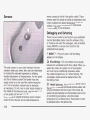
ufik Lock Reeease
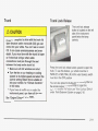
Trunk
TIu
I.
It can be dangerousto drive with the trunk
IIU
open because carbon monoxide (CO) gas can
come into your vehicle.You can’t see or smell
CO. It can cause unconsciousness and even
death. If you must drive with the trunk lid open
or if electrical wiring or other cable
connections must pass through the seal
between the body and the trunk lid:
0 Make sure all other windows are shut.
Turn the fan on your heating or cooling
system to its highest speed and select the
control setting that will force outside air
into your vehicle. See “Climate Controls”
in the Index.
IS
._.”I--.
--
ui-der iiie
instrument panel, open them all theway.
II
-&1-1-
yuu 1 m v e air uuutxs u i - 1 u r
I
~
1
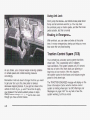
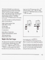
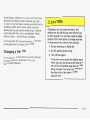
The trunk lock release
button is located on the left
side of the instrument
panel below the lamp
controls.
Press the trunk lock release button upward to open the
trunk. To use this feature, your vehicle must be in
PARK (P) or NEUTRAL (N) and the valet lockout switch
must be in the OFF position.
You can also press the button with the trunk symbol on
the remote keyless entry transmitter to open the
11 uI Ik. T” dis&ie ii-lis ieaiure, set! 7a‘t.iiuckuui Swiicir
A”..
under Theft-Deterrent Systems on page 2- 18.
See “Engine Exhaust” in the Index.
2-1 1
Trunk Lid Tie Down
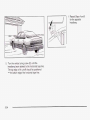
Driving with the trunk lid open can allow
dangerous CO (carbon monoxide) gas to come
into your vehicle. You can’t see or smell CO. It
can cause unconsciousness and evendeath. If
you ever need to drive with your trunk lid
open, then:
Make sure all windows, the rear seat
pass-through and sunroof are closed.
Turn the fan on your heating and cooling
system to its highestspeed, with the
setting on AUTO and temperature between
65°F (18°C) and 85°F (29°C). This forces
fresh outside air into your vehicle.
Open all air ducts on the instrument panel.
,
Don’t use the trunklid tie down if youare
towing a trailer because of the danger of CO.
~
2-12
A
Your vehicle may be equipped with a trunk-lid tie down.
This feature is used to secure the trunk lid if it will
not close completely, such as when carrying large
packages in the trunk. Use the following steps to secure
the trunk lid:
1. Attach the clip end of the tie down to the D ring on
the trunk lid (A).
2. Attach the hook end of the tie down to the striker
located at the center of the trunk sill (B).
3. Tighten the tie down by pulling the free end of the
cord until secure.
4. To remove the tie down, press the clip end release
and loosen the cord.
Notice: The emergency trunk release handle is not
designed to be used to tie down the trunk lid or
as an anchor point when securing items in the trunk.
Your vehicle may be equipped with a rear seat
pass-through door. The button for this feature is located
in the trunk.
I
,
ne rear-seai arrnresi must be down ior ine
pass-through door to open. To release the pass-through
door, Press the PUSH button located in the center of
the trunk panel.
I
Thereis a glow-in-the-darktrunk release handle located
insidethe trunk onthe latch. This handle will glow
following exposure to light. Pull the release handle
upward to open the trunk from the inside.
2-13
I
Leaving children in a vehicle with the windows
closed is dangerous. A child can be overcome
by the extreme heat and can suffer permanent
injuries or even death from heat stroke. Never
leave a child alone in a vehicle, especially with
the windows closed in warm or hot weather.
2-14
Your vehicle has Retained Accessory Power (RAP) that
allows you to use the power windows once the
ignition has been turned off. For more information, see
Retained Accessory Power (RAP) under Ignition
Positions on page 2-22.
Express-Down Window
This feature is on all power windows. Press the down
arrow on the switch to the second position to activate the
express-down feature. If you want to stop the window
as it is lowering, press the down arrow on the switch
again.
Express-Up Window
The power window switches are located on the armrest
neareachwindow.Press
the upordown
arrows on
the switches to raise or lower the windows.
This feature is on both front power windows. Press the
up arrow on the switch to the second position to
activate the express-up feature. If you want to stop the
window as it is raising, Press the UP arrow on the
switch again.
2-15
Programming the Power Windows
Anti-Pinch Feature
If the battery on your vehicle has been recharged,
disconnected or is not working, you will need to
reprogram each front power window for the express-up
feature to work. Before reprogramming, you will need
to replace or recharge your vehicle’s battery.
If a hand, an arm or another object is above the middle
of the window and is in the path of the window when
the express-up feature is active, the window will stop at
the obstruction and express-open to a preset factory
position.
To program each front window, follow these steps:
1. With the ignition in ACC or ON, or when RAP is
active, close all doors.
2. Press and hold the down arrow on the power
window switch until the window has fully opened.
3. Press the up arrow on the power window switch
until the window is fully closed.
4. Continue holding the switch up for approximately
two seconds after the window is completely
closed.
The window is now programmed. Repeat the process
for the other front window.
2-16
,
~
Pressing and holding the power window
control will turn off the anti-pinch feature. If
this happens, a power window won’t stop if
something gets in the way. You or others
could be injured, and your window could be
damaged. Be careful not to press and hold the
powerwindowcontrol.
The rear window lockout
button is located on the
driver’s door armrest next
to the window switches.
Swing down the primary visor to block out glare. It can
also be detached from the center mount and moved
to the side while the auxiliary sunshade remains to block
the glare from the front. The visors also have
side-to-side slide capability.
The visors also have a storage flap.
Lighted Visor Vanity Mirrors
Pull the visor down and lift the cover. Move the slide
switch up or down to brighten or dim the lamp.
Press this button to disable the rear window controls.
The light on the button will illuminate, indicating that the
feature is in use. The rear windows still can be raised
or lowered using the driver’s window switches when the
lockout feature is active.
To restore power to the rear windows, press the button
again. The light on the button will go out.
2-17
Theft-Deterrent Systems
Vehicle theft is a big business, especially in some cities.
Although your vehicle has a number of theft-deterrent
features, we know that nothing we put on it can make it
impossible to steal.
The SECURITY light is
located on the instrument
panel cluster.
SECURITY
If the ignition is off and any door is open, the SECURITY
light will flash, reminding you to arm the system.
To arm the system, do the following:
1. Open the door.
2. Lock the door using the power door lock switch with
the door open or the remote keyless entry
transmitter. The SECURITY light should come on
and stay on.
3. Close all the doors. The SECURITY light should go
off within approximately 30 seconds.
2-18
If a door or a trunk is opened without a key or a remote
keyless entry transmitter, the horn will sound and the
lamps will flash for about 30 seconds.
Remember, the theft-deterrent system won’t arm if you
lock the doors with a key or use the manual door
lock. It activates only if you use a power door lock with
the door open or the remote keyless entry transmitter.
To avoid activating the alarm by accident do the
following:
0
The vehicle should be locked with the door key or
the manual door lock after the doors are closed if
you don’t want to arm the theft-deterrent system.
Always unlock a door with a key or use the remote
keyless entry transmitter. Pressing the unlock
button on the remote keyless entry transmitter
disables the theft-deterrent system. Unlocking a
door any other way will activate the alarm when a
door or the trunk is opened.
If you activate the alarm by accident, unlock the driver’s
door with your key. You can also turn off the alarm
by using the unlock button on the remote keyless entry
transmitter, or by starting the car with a valid key.
Changes or modifications made to this system by other
than an authorized service facility could void
authorization to use the theft system.
Testing the A!arm
1. From inside the uehieie, roii down the window, then
get out of the vehicle, keeping the door open.
2. From outside of the vehicle, with the door open,
lock the vehicle using the power door lock or the
remote keyless entry transmitter and close the door.
Wait 30 seconds until the SECURITY lamp
goes off.
The valet lockout switch is
located inside the
glove box.
3. Reach in and unlock the door using the manual
lock and open the door. The horn will sound and
the hazard lights will flash.
You can turn off the alarm by unlocking the driver's door
with your key, using the unlock button on the remote
keyless entry transmitter or bystarting the car with
a valid key.
If the alarm does not sound when it should, check to
see if the horn works. The horn fuse may be blown. To
replace the fuse, see Fuses and Circuit Breakers on
p y e 5-93. ii iire iuse does noi need io be repiacea, you
may need to have your vehicle serviced.
Press the switch to ON to disable the use of the trunk,
fuel door, garage door opener and cellular telephone
(option). The remote keyless entry transmitter cannot
open the trunk if the valet lockout switch is in ON.
Press this switch to OFF to enable the use of the trunk,
fuel door, garage door opener and optional cellular
telephone.
Locking the glove box with your key will also help to
secure your vehicle.
To reduce the possibility of theft, always arm the
theft-deterrent system when leaving your vehicle.
2-19
PASS-Key@111
PASS-Key@111 Operation
Your PASS-Key@ Ill system operates on a radio
frequency subject to Federal Communications
Commission (FCC) Rules and with Industry Canada.
Your vehicle is equipped with the PASS-Key@Ill
(Personalized Automotive Security System)
theft-deterrent system. PASS-Key@Ill is a passive
theft-deterrent system. This means you don’t have
to do
anything different to arm ordisarm the system. It works
when you insert or remove your key from the
ignition.
This device complies with Part 15 of the FCC Rules.
Operation is subject to the following two conditions:
(1) this device may not cause harmful interference, and
(2) this device must accept any interference received,
including interference that may causeundesired
operation.
This device complies with RSS-210 of Industry Canada.
Operation is subject to the following two conditions:
(1) this device may not cause interference, and (2) this
device must accept any interference received,
including interference that may cause undesired
operation of the device.
When the PASS-Key@Ill system senses that someone
is using the wrong key, it shuts down the vehicle’s
starter and fuel systems. The starter will not work and
fuel will stop being delivered to the engine. Anyone
using a trial-and-error method to start the vehicle will be
discouraged because of the high number of electrical
key codes.
When trying to start the
vehicle, if the engine does
not start and the
SECURITY light comes on,
the key may have a
damaged transponder.
Turn the ignition off and try
again.
Changes or modifications to this system by other than
an authorized service facility could void authorization to
use this equipment.
PASS-Key@ Ill uses a radio frequency transponder in
the key that matches a decoder in your vehicle.
L
2-20
If the engine does not sta.rt, a.nd the key appears to be
undamaged, try another ignition key. At this time,
you may ais0 want to check the fuse. See Fuses and
Circuit Breakers on page5-93. If the engine still
does not start with the other key, your vehicle needs
service. If your vehicle does start, the first key may be
faulty. See your dealer who can service the
PASS-Key@lllto have a new key made.
It is possible forthe PASS-Key@llldecoder to learn the
transponder value of a new orreplacement key. Up to 10
additional keys may be programmed for
the vehicle. This
procedure is for learning additional keys only.
Canadian Owners: If you lose or damage your keys,
only a GM dealer can service PASS-Key@lllto have new
keys made. To program additional keys you will
require two current driver's keys (black in color). You
must add a step to the following procedure. After Step 2,
repeat Steps 1 and 2 with the second current driver's
key. Then continue with Step 3.
To program the new key do the following:
3. Affer the engine has sfaded, turn the key to OFF,
and remove the key.
4. Insert the key to be programmed and turn it to ON
within 10 seconds of removing the previous key.
5. The SECURITY light will turn off once the key has
been programmed. it may not be apparent that the
SECURITY light went on due to how quickly the
key is programmed.
6. Repeat the Steps 1 through 4 if additional keys are
to be programmed.
If you are ever driving and the SECURITY light comes
on and stays on, you will be able to restart your
engine if you turn it off. Your PASS- Key@lllsystem,
however, is not working properly and must be serviced
by your dealer. Your vehicle is not protected by the
PASS-Key@lll system atthis time.
If you lose or damage a PASS-Key@ Ill key, your dealer
to have a new key made.
In an emergency, contact Cadillac Roadside Assistance.
n n n-nn 7 E
C a n 'Rnqr(r;dn Cnnfinn ",,
puyv , e.
vvv
1. Verify that the new key has PK3 stamped on it.
l"UU"'UU
V
V
I "#VU
2. Insert the current driver's key in the ignition
and start the engine. If the engine will not start see
your dealer for service.
2-2 1
Starting and Operating Your
Vehicle
New Vehicle Break-In
Notice: Your vehicle doesn’t need an elaborate
“break-in.” But it will perform better in the long run
if you follow these guidelines:
e
Don’t drive at any one speed - fast or
slow - for the first 500 miles (805 km). Don’t
make full-throttle starts.
e
Avoid making hard stops for the first200 miles
(322km) or so. During this time your new
brake linings aren’t yet brokenin. Hard stops
with new linings can mean prematurewear and
earlier replacement. Follow this breaking-in
guideline every time you get new brake linings.
e
Don’t tow a trailer during break-in. See “Towing
a Trailer” in the index for more information.
Ignition Positions
With the key in the ignition
switch, located on the
instrument panel, you can
turn the key to four
different positions:
Notice: If your key seems stuck in OFF and you
can’t turn it, be sure you are using the correct
key;
if so, is it all the way in? Turn the key only with
your hand. Using a tool to forceit could break the
key or the ignition switch. If none
of this works, then
your vehicle needs service.
OFF: This is the only position in which you can insert
or remove the key. This position also locks the transaxle.
It’s a theft-deterrent feature.
2-22
ACC (Accessory): This pnsitior! !ets you use things
like the radio, windshield wipers, power windows
and optional sunroof when the engine is off. Use ACC if
you must have your vehiclein motion while the engine
is off (for example, if your,vehicle is being pushed
or towed).
P ~ w etc!
r these accessories stops after 10 minutes or if
a door is opened. If you want power for another 10
minutes, close all the doors and turn the ignition key to
ON and then back to OFF. If the cellular phone is
being used while retained accessory power is active,
the timer is suspended to avoid interruption of the call.
The timer resets to 10 minutes at the end of the call.
ON: This is the position for driving.
START: This position starts the engine.
Retained Accessory Power (RAP)
The following accessories on your vehicle may be used
for up to 10 minutes after the ignition key is turned
from ON to OFF:
0
Cellular Phone (If Equipped)
Radio
0
PowerWindows
e
AudioSteeringWheel Controls
Starting Your Engine
Move your shift lever to PARK (P) or NEUTRAL (N).
Your engine won’t start in any other position - that’s a
safety feature. To restart when you’re already moving,
use NEUTRAL (N) only.
Notice: Don’t try to shift to PARK (P)if your
vehicle is moving. If you do, you could damage the
transaxle. Shift to PARK (P) only when your
vehicle is stopped.
1. With your foot off the accelerator pedal, turn your
ignition key to START. When the engine starts, let
go of the key. The idle speed will go down as
ymrr e q i n e gets warm
Sunroof (Option)
2-23
Notice: Holding your key in START for longer than
15 seconds at a time will cause your battery to
be drained much sooner. And the excessiveheat
can damage your starter motor. Wait about15
seconds between each try to help avoid draining
your battery or damaging your starter.
Engine Coolant Heater
Your vehicle may be equipped with an engine coolant
heater.
2. If it doesn’t start within 10 seconds, hold your key in
START forabout 10 seconds at atime until your
engine starts. Wait about 15 seconds between
each try.
3. If your engine still won’t start (or starts but then
stops), it could be flooded with too much gasoline.
Try pushing your accelerator pedal all the way to the
floor and holding it there as you hold the key in
START for about three seconds. If the vehicle starts
briefly but then stops again, do the same thing.
Notice: Your engine is designed to work with the
electronics in your vehicle. If you add electrical
parts or accessories, you could change the way the
engine operates. Before adding electrical equipment,
check with your dealer. If you don’t, your engine
might not perform properly.
2-24
A. Engine Oil Dipstick Location
B. Engine Coolant Heater Cord
C. Transaxle DipsticWFluid Fill Location
2
C
0
2
2
Q
(D
Q
3
2c
E
:
3
3
ra
nI=
w
Q
0
E
0
2
1.
(D
2
(D
5
Q
S
P,
Q
0
0
5
0
U
?
z.
3
3
(D
0
=E
2
5
tD
tD
c
v)
-I
0
Automatic Transaxle Operation
There are several different positions for the shift lever.
suddenly. YOU or others could be injured. To
be sure your vehicle won’tmove, even when
you’re on fairly level ground, always set your
parking brake and move the shiftlever to
PARK (P). See “Shifting Into Park (P)” in the
Index. If you’re pulling a trailer,see “Towing a
Trailer” in the Index.
PARK (P): This position
locks the front wheels. It’s
the best position to use
when you start the engine
because your vehicle
can’t move easily.
Ensure the shift lever is fully in PARK (P) before starting
the engine. Your vehicle has an automatic transaxle
shift lock control system. You have to fully apply
your regular brakes before you can shift from PARK (P)
when the ignition key is in ON. If you cannot shift the
shift lever all the way into PARK (P), ease pressure on
the shift lever and push the shift lever all the way
into PARK (P) as you maintain brake application. Then
move the shift lever into the gear you wish. See
Shifting Out of Park (P) on page 2-32.
It is dangerou, .o get out c. ,,~r vehicle if the
shift lever is not fully in PARK (P) with the
parking brake firmly set. Your vehicle can roll.
Don’t leave your vehicle when the engine
is
running unless you haveto. If you have left the
engine running, the vehicle can move
CAUTION: (Continued)
!-26
I
REVERSE (R): Use this gear to backup.
(0
AuTOifiAiiC GvERDRivE
j: This position is for
normal driving, If YOU need more power for passing, and
Notice: Shifting to REVERSE (Rj while your vehicle
you’re:
is moving forward could damage your transaxle. Shift
9
Going less than 35 mph (55 km/h), push the
to REVERSE (R) only after your vehicle
is stopped.
accelerator pedal about halfway down.
Going about 35 mph (55 km/h) or more, push the
Also use this gear to rock your vehicle back and forth to
get out of snow, ice or sand without damaging your
accelerator all the way down.
transaxle. See If You Are Stuck: In Sand, Mud, Ice or
The transaxle will shift down to the next gear and
Snow on page 4-29 for additional information.
have more power.
NEUTRAL (N): In this position, the engine doesn’t
Notice: If your vehicle seems to start up rather
connect with the wheels. To restart when you’re already
slowly, or if it seems not to shift gears as you go
faster, something may be wrong with a transaxle
moving, use NEUTRAL (N) only. Also use NEUTRAL (N)
system sensor. If you drive veryfar that way, your
when I - - - - - - ~ehicleis bei towed.
vehicle can be damaged. So, if this happens,
have your vehicle serviced rightaway. Until then,
you can use SECOND (2) when you are driving less
than 35 mph (55 km/h) and AUTOMATIC
OVERDRIVE (D) for higher speeds.
Shittlng into a drive gear while )ur engine is
THIRD (3): This position is also used for normal driving,
“racing” (running at high speea) is dangerous.
however, it offers more power and lower fuel economy
Unless vour foot is firmly on the brake pedal,
than HU I UMA I IC; OVtHUHlVE
1.
your vehicle could move very rapidly. You
Here are examples for using THIRD (3) instead of
could lose control andhit people or objects.
AUTOMATIC OVERDRIVE (@ ):
Don’t shift into a drivegear while your engine
is racing.
When driving on hilly, winding roads.
~
(3
2-27
SECOND (2): This position gives you more power. You
can use SECOND (2) on hills. It can help control
your speed as you go down steep mountain roads, but
then you would also want to use your brakes off
and on.
Notice: Don’t shift into SECOND (2) unless you are
going slower than 65 mph (105 km/h), or you can
damage your engine.
FIRST (1): This position gives you even more power
than SECOND (2). You can use it on very steep hills, or
in deep snow or mud.
If the traction control switch is off, your vehicle will not
go into FIRST (1) gear and the vehicle will accelerate
from stop more slowly. This can help in deep snow
or mud conditions. When the traction control is turned
off, a message will light up on the Driver Information
Center (DIC).
2-28
Notice: If your front wheels won’t turn, don’t try to
drive. This might happen if you were stuck in
very deep sand or mud orwere up against a solid
object. You could damage your transaxle. Also,
if you stop when going uphill, don’t hold your
vehicle there with only the accelerator
pedal. This
could overheat and damage the transaxle.Use your
brakes to hold your vehicle in position ona hill.
Performance Shift Display (STS Only)
When your vehicle detects a change in driving
conditions, it will automatically initiate the appropriate
performance shift mode. When this occurs, the
gear display on the instrument panel cluster will change
to indicate that the transaxle has shifted to a different
gear. For example, the gear display on the cluster may
indicate D, 3, 2, or 1 even though the gearshift lever
is still in AUTOMATIC OVERDRIVE (@ 1. Once
the performance shift mode ends, the gear display on
the instrument panel cluster will return to normal.
The parking brake
is
located to the left of the
regular brake pedal,
near the driver’s door.
To set the parking brake, hold the regular brake pedal
down with your right foot and pushthe parking brake
pedal down with your left foot.
If the ignition is on, the brake system warning light on
ld
on If it
the instrument panel cluster s h o ~ ~come
doesn’t, you need to have your vehicle serviced.
?*!hen p ~move
: =ut d PA!?K (P) s: NEUTRAL (N) and
the engine is running, the parking brake should
release. If the parking brake has not been fully released
and you try to drive off with the parking brake on, the
brake system warning light will come on and stay on and
a multiple chime will sound. See Brake System
Warning and Parking Brake Indicator Light on page 3-40
for more information.
If the parking brake doesn’t fully release, you can
manually release the pedal. However, be sure to read
the following paragraphs:
Always shift to PARK (P) before pulling the
manual release lever. If your hand or arm is in
the way of the pedal you could be hurt. The
pedal springs back quickly. Keep your hand
and arm away when you use the manual
release lever.
Before releasing the manual parking brake, be sure to
put the vehicle in PARK (P) and turn the ignition to OFF.
2-29
Reach under the driver’s side of the instrument panel
and pull down on the manual release lever, which
is located behind the parking brake pedal. Pull down on
the yellow tab as shown by the arrow in the illustration.
If the parking brake does not release, you should
have your vehicle towed to your dealer for service.
Notice: Driving with the parking brake on can cause
your rear brakes to overheat. You may have to
replace them, and you could also damage other
parts of your vehicle.
If you are towing a trailer and are parking on a hill, see
Towing a Trailer on page 4-33.
2-30
2. M ~ v the
e shift lever
into PARK (P) by
pushing the lever all
the way toward
the front of your vehicle
and then to the left.
It can be da..derous tc ,et out 01 +ur vehicle
if the shift lever is not fullyin PARK (P) with
the parking brake firmlyset. Your vehicle can
roll. If you have left the engine running, the
vehicle can move suddenly.You or others
could be injured. To be sure your vehicle won’t
move, even when you’re on fairly level ground,
use the steps that follow. If you’re pulling a
trailer, see “Towing a Trailer” in the Index.
1. Hold the brake pedal down with your right foot.
3. With your right foot still holding the brake pedal
down, set the parking brake.
4. Turn the ignition key to OFF.
5. Remove the key and take it with you. If you can
leave your vehicle with the ignition key in your
hand, your vehicle is in PARK (P).
2-31
Leaving Your Vehicle With the Engine
mning
It can be dangerous to leave your vehicle with
the engine running. Your vehicle could move
suddenly if the shift lever is not fully in
PARK (P) with the parking brakefirmly set.
And, if you leave the vehicle with the engine
running, it could overheat and even catch fire.
You or others could be injured. Don’t leave
your vehicle with the engine running.
If you have to leave your vehicle with the engine
running, be sure your vehicle is in PARK (P) and your
parking brake is firmly set before you leave it.
Torque. Lock
If you are parking on a hill and you don’t shift your
transaxle into PARK (P) properly, the weight of
the vehicle may put too much force on the parking pawl
in the transaxle. You may find it difficult to pull the
shift lever out of PARK (P). This is called “torque lock.”
2-32
To prevent torque lock, set the parking brake and then
shift into PARK (P) properly before you leave the
driver’s seat. To find out how, see Shifting lnto Park (P)
on page 2-3 I .
If torque lock does occur, you may need to have
another vehicle push yours a little uphill to take some of
the pressure from the parking pawl in the transaxle,
so you can pull the shift lever out of PARK (P).
Shifting Out of Park (P)
Your vehicle has an automatic transaxle shift lock
control system. You have to fully apply your regular
brakes before you can shift from PARK (P) when
the ignition is ON. See Automatic Transaxle Operation
on page2-26.
If you cannot shift out of PARK (P), ease the pressure
on the shift lever. Push the shift lever all the way
into PARK (P) as you maintain brake application. Then
move the shift lever into the gear you want. If you
ever hold the pedal down but still can’t shift out of
PARK (P), try the following:
1. Turn the ignition key to ACC. Open and close the
driver’s door to turn off the RAP feature.
2. Apply and hold the brake until the end of Step 4.
3. Shift to NEUTRAL (N).
4. Start the vehicle and then shift to the drive gear
you want.
5. Have the vehicle fixed as soon as you can.
Engine Exhaust
Engine exhaust cankill. It contains the gas
carbon monoxide(CO), which you can’tsee or
smell. It can cause unconsciousness and death.
in if:
You might have exhaust corning
0 Your exhaust system sounds strange or
different.
Your vehicle gets rusty underneath.
e Your vehicle was damaged in a collision.
0 Your vehicle was damaged when driving
over high points on the road or over road
debris.
0 Repairs weren’t done correctly.
Your vehicle or exhaust system had been
mrrrlXinrl ; m n u m m ~ u I m v
m m m ~ ~ m r n r n r u
~~nmpaupbm~y.
Things that can burn could touch hot exhaust
parts under your vehicle and ignite. Don’t park
over papers, leaves, dry grass or other things
that can burn.
I
If you ever suspect exhaust is coming into your
vehicle:
e Drive it only with all the windows down to
blow out any
CO; and
0 Have yaw vehick fixed hmediately.
2-33
Running Your Engine While You
Are Parked
It’s better not to park with the engine running. But if you
ever have to, here are some things to know.
J the engine with the climate control
system off could allow dangerous exhaust into
your vehicle. See the earlier Caution under
“Engine Exhaust.’’
Also, idling in a closed-in place can let deadly
carbon monoxide (CO) into your vehicle even if
the fan isat the highest setting. One place this
can happen is a garage. Exhaust - with
CO - can come in easily.NEVER park in a
garage with the engine running.
Another closed-in place can be a blizzard.See
“Winter Driving” in the Index.
2-34
It can be dangerous toget out of your vehicle
if the shift lever is notf i l l y i n PARK (P) with
the parking brake firmlyset. Your vehicle can
roll. Don’t leave your vehicle when the engine
is running unless you haveto. If you’ve left the
engine running, the vehicle can move
suddenly. You or others could be injured.To
be sure your vehicle won’t move, even when
you’re on fairly level ground, always set your
parking brake after you move the shiftlever to
PARK (P).
Follow the proper steps to be sure your vehicle won’t
move. See Shifting Into Park (P) on page 2-31.
If you are parking on a hill and if you’re pulling a trailer,
also see Towing a Trailer on page 4-33.
ling 11~t:mn=
IvriTTOr
PI#hAU.
wt=a
Automatic Dimming Rearview Mirror
with OnStar@
Your vehicle may have an automatic dimming rearview
mirror with Onstar@system controls. For more
information about Onstar@,see QnStat@ System on
page 2-40.
When the automatic dimming feature is turned on, the
mirror automatically changes to reduce glare from
headlamps behind you. A photocell on the mirror senses
when it is becoming dark outside. Another photocell
built into the mirror face senses when headlamps
are behind you.
At night, when the glare is too bright, the mirror will
gradually darken to reduce glare. This change may take
a few seconds. The mirror will return to its clear,
daytime state when the glare is reduced.
&L-.
When cieaning the mirror, use a paper towel or similar
material dampened with glass cleaner. Do not spray
glass cleaner directly on the mirror as that may cause
the liquid cleaner to enter the mirror housing.
Automatic Dimming Rearview Mirror
with OnStar@and Compass
Your vehicle may have an automatic dimming rearview
mirror with a compass display. The mirror also
contains Onstar@controls. For more information see
Onstat@System on page 2-40.
The automatic dimming feature functions the same as
that of the automatic dimming rearview mirror without a
compass. See Automatic Dimming Rearview Mirror
with QnStap on page 2-35.
The mirror also includes an eight-point compass display
in the upper right corner of the mirror face. When on,
LI le
- ~urrspausauiurllaiicaiiy caiiurates as .the venicie
18-
Mirror Operation
is driven.
&
(OdOff): This is the on/off button, located on the
lower left side of the mirror face.
Tc turn the automatic dimming feature GK or off, press
the on/off button. Theindicator light will be illuminated
when the automatic dimming feature is on.
2-35
Mirror Operation
(I> (On/Off): The on/off button is located on the lower
left side of the mirror face for the electrochromic
and compass functions of the rearview mirror.
To turn on the automatic dimming feature,press and hold
the on/off button for about three seconds. To turn off
automatic dimming, press and hold the on/off button for
about three seconds again. The indicator light will
illuminate when this feature is active. The automatic
dimming feature is active each time the vehicle is started.
Compass Operation
Press the on/off button once to turn the compass
on or off.
When the ignition and the compass feature are on, the
compass will show two character boxes for
approximately two seconds. After two seconds, the
mirror will display the compass heading.
Compass Calibration
If after two seconds, the display does not show a
compass heading (for example, N for North), there may
be a strong magnetic field interfering with the compass.
Such interference may be caused by a magnetic
antenna mount, magnetic note pad holder or a similar
magnetic item. If the letter C should ever appear in
the compass window, the compass may need
calibration.
2-36
The mirror can be calibrated by driving the vehicle in
circles at 5 mph (8 km/h) or less until the display readsa
direction.
The compass can be placed in calibration mode
manually by pressing and holding the on/off button until
a C is shown in the compass display.
Compass Variance
The zone is set to zone eight upon leaving the factory.
It will be necessary to adjust the compass to
compensate for compass variance if you live outside
zone eight. Under certain circumstances, as during
a long distance cross-country trip, it will be necessary to
adjust for compass variance. Compass varianceis
the difference between earth’s magnetic north and true
geographic north. If not adjusted to account for
compass variance, your compass could give false
readings.
To adjust for compass variance do the following:
1. Find the current location and variance zone number
on the following zone map.
2. Press and hold the on/off button until a zone
number appears in the display.
\Nhen cleaning the mirror, use a paper towel or similar
material dampened with glass cleaner. Do not spray
glass cleaner directly on the mirror as that may cause
the liquid cleaner to enter the mirror housing.
Outside Power Mirrors
The control on the driver's
door armrest operates both
outside rearview mirrors.
3. Once the zone number appears in the display,
press the on/off button quickly until the correct
zone number appears in the display. Stop pressing
ii~ebuiiwn arid ihe mirror wiii reiurn io normai
operation. If C appears in the compass window, the
compass may need calibration. See Compass
Calibration listed previously.
Fjress (Rj on the seiector switch to cnoose the right
mirror or (L) to choose the left mirror. The center position
is off and will not move the mirrors if the control pad
is touched.
2-37
To adjust a mirror, press the arrows on the control pad
to move the mirror in the direction you want the
mirror to go. Adjust each mirror so you can see the side
of your vehicle and the area behind your vehicle.
The mirrors can be manually folded inward to prevent
damage when going through an automatic car wash. To
fold, push the mirror toward the vehicle. To return the
mirror to its original position, push outward. Be sure
to return both mirrors to their original unfolded positions
before driving.
The mirrors can also be programmed for personalization
and parallel parking feature if you have the optional
memory package. For more information, see Memory
Seat, Mirrors and Steering Wheel on page 2-49and DIC
Vehicle Personalization on page 3-60.
Outside Automatic Dimming Mirror
If your vehicle is equipped with this feature, the
driver’s side mirror will adjust for the glare of headlamps
behind you. This feature is controlled by the on and
off settings on the automatic dimming rearview mirror.
See Automatic Dimming Rearview Mirror with Onstar@
on page 2-35.
2-38
Outside Curb View Assist Mirror
If your vehicle is equipped with memory mirrors, it will
also be capable of performing the curb view assist mirror
feature. This feature will cause the passenger’s mirror
to tilt to a factory programmed position when the vehicle
is in REVERSE (R). This feature may be useful in
allowing you to view the curb when you are parallel
parking.
When the vehicle is shifted out of REVERS€ (R) and a
five-second delay has occurred, the passenger’s
mirror will return to its original position.
If further adjustment is needed after the mirror is tilted
the mirror switch may be used.
This feature can be enabled/disabledthrough the Driver
Information Center (DIC). See DlC Vehicle
Personalization on page 3-60 for more information.
Your passenger’s side mirror is convex. A convex
mirror’s surface is curved so you can see more from the
driver’s seat. This mirror does not have a dimming
feature.
When you operate the rear window defogger, it also
warms both outside mirrors to help clear them of fog or
ice. See Dual Cfimate Control System on page 3-25
for more information.
A convex mirror can make t 1gs (like other
vehicles) look farther away than they really are.
If you cut too sharply into the right lane, you
could hit a vehicle on your right. Check your
inside mirror or glance over your shoulder
before changing lanes.
2-39
Onstar@
Onstar* Services
Onstar@provides a number of service plans. Some of
the services currently provided by Onstar@are:
Automatic Notification of Air Bag Deployment
EmergencyServices
Roadside Assistance Stolen Vehicle Tracking
AccidentAssist
RemoteDoorUnlock
Onstar@uses global positioning system (GPS) satellite
technology, wireless communications, and call centers
to provide you with a wide range of safety, security,
information and convenience services. An Onstar@
subscription plan is included in the price of your vehicle.
You can upgrade or extend your Onstar@services to
meet your needs.
A complete Onstar@user’s guide and the terms and
conditions of the Onstar@ Subscription Service
Agreement are included in your vehicle’s glove box
literature. For more information, visit www.onstar.com,
contact Onstar@at 1-888-4-ONSTAR (1-888-466-7827),
or press the blue Onstar@button to speak to an
Onstar@24 hours a day, 7 days a week.
2-40
Remote Diagnostics
Onstar@MED-NET (Requires separate activation
and annual fee on some plans)
Online and Personal Concierge Services
Route Support
RideAssist
information andConvenienceServices
Onstar* Personal Calling
With Onstar@Personal Calling, you have a safer way to
stay connected while driving. It’s a hands-free wireless
phone that’s integrated into your vehicle. You can place
calls nationwide using voice-activated dialing with no
contracts, no roaming charges and no access fees. To
find out more about Onstar@Personal Calling, refer
to the Onstar@user’s guide in your vehicle’s glove box,
or call Onstar@ at1-888-4-ONSTAR (1-888-466-7827).
With OnStap Virtuai Advisor you can listen to the news,
entertainment and informative topics, such as traffic
and weather reports. You are able to listen and reply to
your e-mail through your vehicle’s speakers.
A completed Subscription Service Agreement is required
prior to delivery of Onstar@services and prepaid
calling minutes are also required for Onstar@Personal
Calling and OnStap Virtual Advisor use. Terms and
conditions of the Subscription Service Agreement can be
found at www.onstar.com.
Onstar@Steering Wheel Controls
You can use the steering wheel controls with Onstar@.
The controls are located
on the left side of the
steering wheel.
Press the tap part of the control to access OnStap.
You will hear a ready prompt from the system, and
then you can begin your Onstar@session or begin
making calls.
If your vehicle has the optional Navigation system or
cellular phone, the ready prompt will come from
that system first. You must say the word phone to
access Onstar@.
If your vehicle has both optional systems, the ready
prompt will come from the Navigation system first. When
you say the word phone after the ready prompt, you
will access the cellular phone.
If you prefer to use Onstar@to make calls, you must
repeat the word phone again after the cellular
phone ready prompt.
To end a communication session, press the bottom part
of the control that says END.
2-4 1
HomeLink@ Transmitter
and (2) this device must accept any interference
received, including interference that may cause
undesired operation.
This device complies with RSS-210 of Industry Canada.
Operation is subject to the following two conditions:
(1) this device may not cause interference, and (2) this
device must accept any interference, including
interference that may cause undesired operation of the
device.
Changes and modifications to this system by other than
an authorized service facility could void authorization
to use this equipment.
Programming the HomeLink
Transmitter
HomeLink@, a combineduniversal transmitter and
receiver, provides a way to replace up to three
hand-held transmitters used to activate devices such as
gate operators, garage door openers, entry door
locks, security systems and home lighting. Additional
HomeLink@information can be found on the internet at
www.homelink.com or by calling 1-800-335-351 5.
If your vehicle is equipped with the HomeLink@
Transmitter, it complies with Part 15 of the FCC Rules.
Operation is subject to the following two conditions:
(1) this device may not cause harmful interference,
2-42
Do not use the HomeLink@ Transmitter with any garage
door opener that does not have the “stop and reverse”
feature. This includes any garage door opener model
manufactured before April 1, 1982.
Keep the original transmitter for use in other vehicles as
well as for future HomeLink@ programming.It is also
recommended that upon the sale of the vehicle,
the programmed HomeLink@ buttons should be erased
for security purposes. Refer to “Erasing HomeLinka
Buttons” or, for assistance, contact HomeLink@ onthe
internet at: www.homelink.com or by calling
1-800-355-3515.
Be sure that people and objects are c!ear nf the garage
door or gate operator you are programming. When
programming a garage door, it is advised to park outside
of the garage.
4. The indicator !ight wi!! f!ash s!ow!y at first and then
rapidly after HomeLink@successfully receives the
frequency signal from the hand-held transmitter.
Release both buttons.
It is recommended that a new battery be installed in
your hand-held transmitter for quicker and mure
accurate transmission of the radio frequency.
5. Press and hold the newly-trained HomeLink@button
and observe the indicator light.
I f the indicator light stays on constantly,
programming is complete and your device should
activate when the HomeLink@button is pressed and
released.
To program the remaining two HomeLinkO buttons,
begin with Step 2 under “Programming HomeLink@.”
Do not repeat Step 1 as this will erase all of the
programmed channels.
If the indicator light blinks rapidly for two seconds
and then turns to a constant light, continue with
Steps 6 through 8 following to complete the
programming of a rolling-code equipped device
(most commonly, a garage door opener).
Your vehicle’s engine should be turned off while
programming the transmitter. Follow these steps to
program up to three channels:
1. Press and hold down the two outside buttons,
releasing only when the indicator light begins to
flash, after 20 seconds. Do not hold down the
buttons for longer than 30 seconds and do not
repeat this step to program a second and/or third
transmitter to the remaining two HomeLink@buttons.
2. Position the end of your hand-held transmitter about
1 to 3 inches (3 to 8 cm) away from the HomeLink@
buttons while keeping the indicator light in view.
3. Simultaneously press and hold both the desired
button on HomeLink@and the hand-held transmitter
button. Do not release the buttons until Step 4
has been completed.
Some entry gates and garage door openers may
require yGu tG substitute Step 3 with the prGcedure
noted in “Gate Operator and Canadian
Programming” later in this section.
6. At the garage door opener receiver (motor-head
.,-:t\
U I IIL)
;..
th,.
1 1 I L I IC
m_r_m,.
yal a y c ,
th-
1 u b a t G LI IC
!,,,,,
iil
Leal I I
VI
((CmnrJ;”
UI I IUI L
button. This can usually be found where the hanging
antenna wire is attached to the motor-head unit.
7. Firmly press and release the “Learn” or “Smart”
button. The name and color of the button may
vary by manufacturer.
You will have 30 seconds to start Step 8.
2-43
8. Return to the vehicle. Firmly press and hold the
programmed HomeLink@button for two seconds,
then release. Repeat the press/hold/release
sequence a second time, and depending on the
brand of the garage door opener (or other rolling
code device), repeat this sequence a third time
to complete the programming.
HomeLink@should now activate your rolling code
equipped device.
To program the remaining two HomeLink@buttons,
begin with Step 2 of “Programming HomeLink@.”Do not
repeat Step 1.
Gate Operator and Canadian
Programming
Canadian radio-frequency laws require transmitter
signals to “time out” or quit after several seconds of
transmission. This may not be long enough for
HomeLink@to pick up the signal during programming.
Similarly, some U.S. gate operators are manufactured to
“time out” in the same manner.
If you live in Canada, or you are having difficulty
programming a gate operator by using the
“Programming HomeLink@”procedures (regardless of
where you live), replace Step 3 under “Programming
HomeLink@”with the following:
2-44
Continue to press and hold the HomeLink@ button while
you press and release every two seconds (cycle)
your hand-held transmitter until the frequency signal has
been successfully accepted by HomeLink@. The
indicator light will flash slowly at first and then rapidly.
Proceed with Step 4 under “Programming HomeLink@”
to complete.
Using HomeLink*
Press and hold the appropriate HomeLink@ button for at
least half of a second. The indicator light will come
on while the signal is being transmitted.
Erasing HomeLink* Buttons
To erase programming from the three buttons do the
following:
1. Press and hold down the two outside buttons until
the indicator light begins to flash, after 20 seconds.
2. Release both buttons. Do not hold for longer than
30 seconds.
HomeLink@is now in the train (learning) mode
and can be programmed at any time beginning with
Step 2 under “Programming HomeLink@.”
Individual buttons can not be erased, but they can be
reprogrammed. See “Reprogramming a Single
HomeLink@Button” next.
SP-Z
Storage Areas
Glove Box
The glove box is located in front of the passenger’s seat
on the instrument panel. To lock the glove box door,
insert the master key into the lock cylinder and
turn it clockwise. Turn the key counterclockwise to
unlock the door.
Center Console Storage Area
The center console comes with a storage tray, a
storage compartment for CDs or tapes, a dual cupholder
that unfolds, a coinholder, an optional phone and an
armrest. The cupholder can be opened by pressing on
the surface panel located in front of the armrest and
unfolding it. Close the lid to secure it.
Map Pocket
Cellular Telephone
Your vehicle may have been prewired for dealer
installation of a portable cellular telephone system. The
system has steering wheel telephone controls and
information output through the Driver Information Center
(DIC). Voice activation with remote record and
hands-free operation are standard features. For more
information, contact your dealer. A user’s guide is
provided with the telephone.
2-46
The mapktorage pockets are located on each front door
as well as on the passenger’s and driver’s seatbacks.
Assist Handles
A handle above each door can be used when getting
out of your vehicle.
For your convenience, a garment hook is attached to
each rear assist handle.
Umbrella Holder
The driver’s and passenger’s front seat cushion may be
equipped with an umbrella holder. Gently slide the
umbrella into the slot located under the front portion of
the driver’s or passenger’s seat cushion.
Your vehicle may be equipped with a convenience net.
The net attaches to the floor of the trunk. Put small
loads, like grocery bags, behind the net. It can help keep
them from falling over during sharp turns or quick
starts and stops.
The net is not for larger, heavier loads.Store them in the
trunk as far forward as you can. Whennot using the net,
hook the net to the tabs securing it to the sill plate.
Floor Mats
Your vehicle is equipped with rubber-backed front and
rear floor mats. Keep them clean by vacuuming and
using a spot cleaner, if necessary. Do not
machine wash.
2-47
Sunroof
Press and release the ROOF switch rearward to the
second position to express-open the glass panel to the
comfort stop position, approximately half-way open.
The comfort stop position is designed to help reduce
noise and make the rear seat passengers more
comfortable.
The glass panel may then be fully opened by pressing
the ROOF switch again.
If you press and hold the ROOF switch in the
express-open position for more than one second, the
express-open operation will be over-ridden and the
sunroof will stop when the switch is released.
The two switches that operate the optional sunroof are
located on the overhead console and include VENT,
ROOF, open and close.
Press and hold the ROOF switch rearward to the first
position to open the glass panel and sunshade.
The sunshade also can be opened or closed manually.
To close the glass panel, press and hold the ROOF
switch forward. As the sunroof reaches the closed
position, it will open slightly toward the vent position and
then drop down to the closed position to provide a
better seal.
To stop the glass panel when express opening, press
the ROOF or VENT switch forward or rearward and
release.
To vent the glass panel, press and hold the VENT
switch in the open position. The sunshade must
be opened manually when using the vent position. To
close the glass panel, press and hold the VENT
switch in the close position.
The ROOF and VENT switches work only when the
ignition is on or when RAP is active. See Retained
Accessory Power (RAP) underIgnition Positions
on page 2-22.
Memory Seat, Mirrors and Steering
Wheel
If your vehicle has this
feature, the controls are
located on the driver's door
panel.
These buttons are used to program and recall memory
settings for the driver's seating and outside rearview
m i r r n v nnritinnr
pvCI,,,v,tu.
1 1 1 1 1 I",
I
Irn
VU"
thn.
f n l l n l r r i nay
n ctnnc tn
,I IU l " l l " Y Y l l
U & " p J &"
3. Within five seconds, press button 1 for Driver 1. A
single beep will sound through the driver's side
front speaker to let you know that the position has
been stored.
A second mirror, seating and steering wheel position
can be programmed by repeating the above steps and
pressing button 2 (for Driver 2). Each time a memory
button is pressed, a single beep will sound. Each
time button 1 or 2 is pressed and released while the
vehicle is in PARK (P), the memory positions will
be recalled. If the vehicle is not in PARK (P), the
memory buttons must be pressed and held to recall the
stored positions.
If you use the remote keyless entry transmitter to enter
your vehicle, automatic seat and mirror movement
will occur. The numbers on the back of the transmitters,
1 and 2, correspond to the numbers on the buttons
on the door panel.
rivnnr9r-n
yB"ylu8
I I
each button:
1. Adjust the driver's seat (including the seatback
recliner, lumbar, head restraint and shoulder belt
height adjustments), both outside mirrors and
the steering whee! to a comfortable position.
When the key is placed in the ignition in OFF and you
have entered the vehicle without using the remote
keyless entry transmitter, the seats and mirrors
will automatically adjust to the programmed position of
the last driver.
2-49
To stop recall movement of the memory feature at any
time, press one of the power seat controls or memory
buttons.
Two personalized exit positions can be set by first
recalling the driving position (by pressing 1 or 2), then
positioning the steering wheel and seat in the desired
exit positions. Then press and release the
MEMORY SET button and, within five seconds, press
the EXIT button. With the vehicle in PARK (P), the
exit position for the previously set driver can be recalled
by pressing the EXIT button. The mirrors, power
lumbar and shoulder belt height positions will not be
stored or recalled for the exit positions.
2-50
Further programming for automatic seat and mirror
movement can be done using the Driver Information
Center (DIC). You can select or not select the following:
0
Automatic seat and mirror movement when the
vehicle is unlocked with the remote keyless
entry transmitter, or
automatic seat and mirror movement when a key is
placed in the ignition.
For programming information, see DIC Vehicle
Personalization on page 3-60.
Section 3
Instrument Panel
Instrument
Panel
Overview
......
..............3.4
Hazard
Warning
Flashers ...
..................3.6
Other
Warning
Devices ..
..............3.6
Horn .............................................................
3.6
Tilt Wheel .....................................................
3.7
Turn Signal/Multifunction Lever ......................... 3.8
Exterior Lamps ............................................. 3.15
Interior Lamps .............................................. 3.19
Ultrasonic Rear Parking Assist (URPA) ............3.22
Accessory Power Outlets ............................... 3.23
Ashtrays and Cigarette Lighter ........................ 3-24
Climate Controls ............................................ 3.25
Dual Climate Control System ...................... 3.25
Outlet
Adjustment
.........................
....3.29
Rear Climate Control System ......................... 3.30
Passenger Compartment Air Filter ...................3.32
Steering Wheel Climate Controls ..................... 3.32
Climate Controls Personalization ..................... 3.33
warning Lights, Gages anu Cnuicators ............. 3.34
Instrument Panel Cluster ...............................
-3-35
Speedometer and Odometer ........................... 3.36
Tachometer ................................................. 3.38
..
Safety Belt Reminder Light ............................. 3-38
Air Bag Readiness Light ................................ 3-39
Charging System Light .................................. 3-40
BrakeSystemWarningand
Parking Brake
Indicator Light ........................................... 3-40
Anti-Lock Brake System Warning Light .............3-41
Traction Control System (TCS) Warning Light ...3-42
Engine Coolant Temperature Warning Light ......3-42
Engine Coolant Temperature Gage ..................3-43
Malfunction Indicator Lamp ............................. 3-43
Oil Pressure Light ......................................... 3-46
Security Light ............................................... 3-47
Fog Lamp Light ............................................ 3-47
Lights On Reminder ...................................... 3-47
Cruise Control Light ...................................... 3-48
Fuel Gage ................................................... 3-48
Driver
Information
Center
(DIC)
..
............. 3-49
DIC Controls and Displays .....
................. 3-49
D I P \Alorn;nr.,IvIL-JJuybJ
. . . . . . . . . . . . . . . . . . u9 G r )
Climate Controls and Radio System
Personalization .......................................... 3-59
DIC Vehicle Personalization ............................ 3-60
~ ~ I C I , - C I O C . C I ~
U I U
V V u I I I I I I y J
U I I U
U L
3- 1
Section 3
instrument Panel
Trip Computer ................................................
Oil Life Indicator ...........................................
Audio System(s) .............................................
Setting the Time for Radios without Radio
Data Systems (RDS) ..................................
Setting the Time for Radios with Radio Data
Systems (RDS) .........................................
Radio with Cassette and
CD (Base Level) ...................................
Radio with Cassette and CD
(Up Level) ................................................
NavigatiodRadio System ...............................
3-2
3-71
3.71
3.72
3.72
3-72
3.73
3.80
3.91
Console-Mounted CD Changer ........................ 3.91
Radio Personalization with Home and Away
Feature ................................................... -3-94
Theft-Deterrent Feature .................................. 3.95
Audio Steering Wheel Controls ....................... 3.95
Understanding Radio Reception ...................... 3.96
Care of Your Cassette Tape Player .................3.96
Care of Your CDs ......................................... 3-98
Care of Your CD Player ................................ 3.98
Diversity Antenna System .............................. 3.98
XMTM Satellite Radio Antenna System .............3.98
€-E
A.Air Outiets
B. Driver Information Center (DIC) Buttons
C.Turn Signal/Multifunction Lever
D. Climate Controls and Onstar@
Steering Wheel Controls
(or Cellular Telephone Controls, If Equipped)
E. Instrument Panel Cluster
F. Windshield WiperlWasher Lever
G. Audio Steering Wheel Controls
H. IgnitionSwitch
I. Air Outlet Thumbwheel
J. Hazard Warning Flasher Button
K. Audio System
L. Exterior Lamp Controls
M. Hood Release
N. Fuel Door Release
0. Trunk Release Button
P. Cruise Control
Q. Horn
R. Heated Seat Controls
S. Traction Control Switch
T. Console Shift Lever
U. Convenience Storage/Optional Ashtray
V. Climate Controls
W. GloveBox
3-5
The hazard warning button
is located on the center of
the instrument panel
between the two air vents.
Hazard Warning Flashers
Your hazard warning flashers work no matter what
position the key is in, and even if the key isn’t in.
Press the button to make the front and rear turn signal
lamps flash on and off. Press the button again to
turn the flashers off.
When the hazard warning flashers are on, the turn
signals won’t work.
Your hazard warning flashers let you warn others. They
also let police know you have a problem. Your front
and rear turn signal lamps will flash on and off.
Other Warning Devices
If you carry reflective triangles, you can set one up at
the side of the road about 300 feet (100 m) behind your
vehicle.
Horn
The horn can be sounded by pressing on the center of
the steering wheel pad.
3-6
3
L
i*y
Totiltthewheel,
hold thewheel and pull the lever. Then
movethewheeltoacomfortable
position and release
the lever to lock the wheel in place.
To operate the power tilt feature, push the control up
and the steering wheel will tilt up. Push the control down
and the steering wheel will go down.
If the power tilt control is pressed upor down and held
in that position, there will be aslightmovement and
control is
the steering wheel
approximately one degree in thedirection commanded.
3-7
Push the control forward and the steering wheel moves
toward the front of the vehicle. Push the control
rearward and the steering wheel moves toward the rear
of the vehicle. To set the memory position, see DIC
Vehicle Personalization on page 3-60 and Memory Seat,
Mirrors and Steering Wheel on page 2-49.
Turn SignaVMultifunction Lever
The lever located on the left side of the steering column
includes the following:
Turn and Lane Change
Signals
HeadlampHigh/Low-BeamChanger
Flash-To-Pass
For information on the exterior lamps, see Exterior
Lamps on page 3-15.
3-8
Turn and Lane-Change Signals
To signal a turn, move the lever on the left side of the
steering wheel all the way up or down. The lever returns
automatically when the turn is complete.
hl
t
i
An arrow located on the
instrument panel cluster
will flash in the direction of
the turn or lane change.
Raise or lower the lever until the arrow starts to flash to
signal a lane change. Hold it there until the lane
change is complete. The lever returns when it is
released.
If the turn signal is left on, a warning chime will sound
and the Driver Information Center (DIC) will display
TURN SIGNAL ON after driving about a mile to remind
you to turn it off.
Arrows that flash rapidly when signaling for a turn or
lane change may be causedby a burned-out signal bulb.
Other drivers won’t see the turn signal.
Replace burned-out bulbs to help avoid possible
accidents. Check the fuse and for burned-out bulbs if
the arrow fails to work when signaling a turn. See Fuses
and Circuit Breakers on page 5-93.
When the low-beam headlamps are on, push the turn
signal lever away from you to change the headlamps to
high beam.
This light on the instrument
panel cluster will be on,
indicating high-beam
usage.
Pull the turn signal lever toward you to return to
low-beam headlamps.
-.
I t i s feature lets you use the high-beam headlamps to
signal the driver in f m ~of
t
YOU
that YOU Want to Pass-
Pull the turn signal lever toward you briefly to
flash-to-pass. When you do, the following will occur:
If the headlamps are either off or in the Daytime
Running Lamps (DRL) mode, the high-beam
headlamps will turn on. They’ll stay on as long as
you hold the lever there. Release the lever to
turn them off.
If the headlamps are on low beam, they will remain
active and the high beam will also illuminate until
you release the lever.
3-9
Nindshield Wipers
INT (Delay): Move the lever up to the INT position,
then turn the INT ADJ band, which is located on
the lever, to adjust the delay time. The higher you turn
the INT ADJ band, the more frequently the wipers
will operate.
OFF: Lower the lever to its resting position (OFF) to
turn off the wipers.
MIST: Pull the lever down once and release it for a
single wipe cycle. For more cycles, hold the lever down
in the MIST position longer.
To wash the windshield, press the button located at the
tip of the lever.
You can control the windshield wipers by moving the
lever with the wiper symbol on it. This lever is located on
the right side of your steering column. For information
on wiper-activated headlamp operation, refer to Exterior
Lamps on page 3-75.
The following is a list of the available settings:
LO or HI: Move the lever up to LO for steady wiping at
a slow speed. Move the lever higher to HI for steady
wiping at a high speed.
3-10
Be sure to clear ice and snow from the wiper blades
before using them. If they're frozen to the windshield,
carefully loosen or thaw them. If the blades do become
damaged, get new blades or blade inserts.
Heavy snow or ice can overload the wiper motor. A
circuit breaker will stop the motor until it cools. Clear
away snow or ice to prevent an overload.
Your vehicle is equipped with wiper-activated
headlamps. After the windshield wipers have been on
for approximately six seconds, the headlamps will
automatically turn on. See Wiper Activated Headlamps
under Exterior Lamps on page 3-75for more
information.
Your vehicle may be equipped with RainsenseTMii
wipers. The moisture sensor for this feature is mounted
on the interior side of the windshield below the
rearview mirror and is used to automatically operate the
wipers by monitoring the amount of moisture build-up
on the windshield. Wipes occur as needed to clear
the windshield depending on driving conditions and the
sensitivity setting. In light rain or snow, fewer wipes
will occur. In heavy rain or snow, wipes will occur more
frequently. The RainsenseTM wipers operate in a
delay mode as well as a continuous low or high speed
as needed. If the system is left on for long periods
of time, occasional wipes may occur without any
moisture on the windshield. This is normal and indicates
that the RainsenseTM system is activated.
The RainsenseTM system can be activated by moving
the wiper stalk up to the INT position and turning the INT
ADJ band to one of the five sensitivity levels. The
bottom INT ADJ position is the lowest sensitivity setting,
level one. This allows more rain or snow to collect on
the windshield between wipes.Turning the INT ADJ
band away from you to thehigher sensitivity levels
allows less rain or snow to collect on the windshield
between wipes.
The top positior! is the highest sensitivity setting, !eve!
five. A single wipe will occur each time you turn the INT
ADJ band to a higher sensitivity level to indicate that
the sensitivity level has been increased.
Notice: The wipers must be turned off when going
through a car wash to avoid damage.
The MIST and “wash” cycles operate as normal and are
not affected by the RainsenseTMfunction. The
RainsenseTMsystem can be overridden at any time by
manually changing the wiper control to LO or HI
speed.
When RainsenseTMis active, the headlamps will turn on
automatically. The headlamps will turn off again once
the wipers turn off if it is light enough outside. If it
is dark, they will remain on. See Wiper-Activated
Headlamps under Exterior Lamps on page 3-75 for more
information.
Nofice: Do not place stickers or other items on the
s11-f3pp &ri~t!\/J IE frnnt
..----nf
-. thn
-..moisture sensor. Doing this could cause the
moisture sensor to malfunction.
pytpri~rglass
3-11
Cruise Control
Windshield Washer
The windshield washer has both a “demand” mode and
a “programmed” mode, depending on the amount of
windshield washer fluid you need.
In freezing weather, don’t use your washer
until the windshield is warmed. Otherwise the
washer fluid can form ice on the windshield,
blocking your vision.
I
I
To spray washer fluid on the windshield in the
programmed mode, press and release the button on the
tip of the lever. The washer will provide a measured
amount of fluid to the windshield and the wiper will either
stop or return to your original wiping speed. To spray
washer fluid on the windshield in the demand mode,
press and hold the button until you have enough fluid,
and the wipers will either stop or return to your
original wiping speed.
The buttons to operate cruise control are located on the
steering wheel.
CHECK WASHER FLUID will be displayed on the Driver
Information Center (DIC) when the washer fluid
reaches a low level.
When you apply your brakes, the cruise control
shuts off.
3-12
With cruise control, you can maintain a speed of
approximately 25 mph (40 km/h) or more without
keeping your foot on the accelerator. This is helpful on
long trips. Cruise control does not work at speeds
below about 25 mph (40 km/h). When cruise control is
on, you will see a CRUISE light on the instrument panel
cluster.
*
Cruise control can be dangerous where
you can’t drive safelyat a steady speed.
So, don’t use your cruise control on
winding roads or in heavy traffic.
Cruise control can be dangerous on
slippery roads. On such roads, fast
changes in tire traction can cause
needless wheel spinning, and you could
lose control. Don’t use cruise control on
slippery roads.
If your vehicle is in cruise control when the traction
control system begins to limit wheel spin, the cruise
control will automatically disengage. See Traction
Control System (TCS) on page 4-8. When road
conditions allow you to safely use it again, you may turn
&I,-,
,.:,
--.-L..-l
11 IC LI U I ~ CLUI ILI V I
I---I.
u a b n V II .
If you leave your cruise control on wkem you’re
not using cruise, you might hit a button and go
into cruise when you don’t wantto. You could
be startled and even lose control. Keep the
cruise control switchoff until you want to use
cruise control.
1. Press CRUISE ON/OFF, located on the bottom left
of the steering wheel, to turn cruise control on. An
indicator light will come on to show that the
cruise control is on.
2. Get up to the speed you want.
3. Press SETICST (coast) located on the bottom right
of the steering wheel. The CRUISE liaht will display
on the instrument panel cluster.
4. Remove your foot from the accelerator pedal.
3-13
Resuming a Set Speed
Suppose you set your cruise control at a desired speed
and then you apply the brake. This shuts off the
cruise control. But you don’t need to reset it.
Once the vehicle is traveling approximately 25 mph
(40 km/h) or more, you can press RES/ACC
(resume/accelerate) to return to your desired preset
speed. The CRUISE light will be displayed again.
The vehicle will return to and stay at your preset speed.
If you press and hold RES/ACC, the vehicle speed
will increase until you release the button or apply the
brake. Unless you want to go faster, do not press
and hold RES/ACC.
Increasing Speed While Using Cruise
Control
There are two ways to go to a higher speed:
Use the accelerator pedal to get to the higher
speed. Press SET/CST, then release it and
the accelerator pedal. You will now cruise at the
higher speed.
0
Press RES/ACC. Hold it there until you get up to
the speed that you want, and then release it. To
increase your speed in very small amounts, briefly
press RES/ACC and then release it. Each time
you do this, your vehicle will speed up
approximately 1 mph (1.6 km/h) faster.
The accelerate feature will only work after you have set
the cruise control speed by pressing SET/CST.
3-14
Reducing Speed While Using Cruise
Control
There are two ways to reduce your speed while using
cruise control:
Press SET/CST until you reach the lower speed
you want, then release it.
To slow down in very small amounts, press
SET/CST briefly. Each time you do this, the vehicle
will slow down approximately 1 mph (1.6 km/h).
Passing Another Vehicle While Using
Cruise Control
Use the accelerator pedal to increase your speed.
When you take your foot off the pedal, your vehicle will
slow down to the cruise control speed you set earlier.
Using Cruise Control on Hills
How well your cruise control will work on hills depends
upon your speed, load and the steepness of the
hills. When going up steep hills, you may have to step
on the accelerator pedal to maintain your speed.
When going downhill, you may have to brake or shift to
a lower gear to keep your speed down. Applying the
brake or shifting into a lower gear will take you out
of cruise control. If you need to apply the brake or shift
to a lower gear due to the grade of the downhill
slope, you may not want to attempt to use your cruise
control feature.
Ending cruise Control
To turn off the cruise contr~l,step light!y on the brake
pedal or press CRUISE ON/OFF on the steering wheel.
Erasing Speed Memory
When you turn off the cruise control or the ignition, your
cruise control set speed memory is erased.
0 (0~1:~
~ r ~the
i ncontroi
g
to this position turns off
all lamps except the Daytime Running Lamps (DRL).
%)d
(Parking Lamps): Turning the control to this
position turns on the parking lamps together with the
following:
* SidemarkerLamps
Taillamps
Exterior Lamps
@
The control located on the
left side of the instrument
panel operates the
exterior lamps.
License Plate Lamps
Instrument Panel Lights
The parking brake indicator light will come on and stay
on when the parking lamps are on with the engine
off and the ignition in ACC or ON.
d) (Headlamps): Turning the control to this position
turns on the headlamps, together withthe previously
listed lamps and lights.
/
Your vehicle may be equipped with High Intensity
Discharqe (HID) headlamps. These headlamps come on
at a lower intensity and gradually increase to full
brightness.
-g-(Exterior Lamp Control):
Turn the control with this
symbol on it to operate the exterior lamps.
The exterior lamp control has three positions:
3-15
Wiper-Activated Headlamps
This feature activates the headlamps and parking lamps
after the windshield wipers have been in use for
approximately six seconds. To operate, the Twilight
Sentinel@feature must be turned on.
When the exterior lamp control is in the off or in the
parking lamp position and the wiper control is on INT,
LO or HI, the HEADLAMPS SUGGESTED message will
appear on the Driver Information Center (DIC).
When the ignition is turned to OFF, the wiper-activated
headlamps will immediately turn off. The wiper-activated
headlamps will also turn off if the Twilight Sentinel@
or the windshield wipers are turned off.
Lamps On Reminder
A warning chime will sound if the exterior lamp control
is left on in either the headlamp or parking lamp position
and the driver’s door is opened with the ignition off.
Daytime Running Lamps
Daytime Running Lamps (DRL) can make it easier for
others to see the front of your vehicle during the
day. DRL can be helpful in many different driving
conditions, but they can be especially helpful in the short
3-1 6
periods after dawn and before sunset. Fully functional
daytime running lamps are required on all vehicles
first sold in Canada.
The DRL system will make the high-beam headlamps
come on at reduced brightness when the following
conditions are met:
It is still daylight and the ignition is on,
the exterior lamp control is in the off position and
the transaxle is not in PARK (P).
When DRL are on, only your high-beam headlamps (at
reduced brightness) will be on. No other exterior
lamps such as the parking lamps, taillamps, etc. will be
on when the DRL are being used. Your instrument
panel won’t be lit up either.
When the Twilight Sentinel@ leveris on and it’s dark
enough outside, the high-beam headlamps (at reduced
intensity) will turn off and normal low-beam headlamp
operation will occur.
When the Twilight Sentinel@ leveris on and it’s brighr
enough outside, the regular lamps will go off, and
the high-beam headlamps at reduced brightness will
take over.
If it's dark enough OL!tSidF! and the Twi!igh? Sentine!@
lever is off, a HEADLAMPS SUGGESTED message will
display on the Driver's information Center (DiCj. This
message informs the driver that turning on the exterior
lamps is recommended even though the DRL are
still illuminated. Turning on the Twilight Sentinel@ orthe
headlamps will deactivate the DRL and remove the
HEADLAMPS SUGGESTED message. If the parking
lamps or the fog lamps were turned on instead, the DRL
will still deactivate and the HEADLAMPS SUGGESTED
message will continue to be displayed.
\nlher! the innitinn
Y ' ''..-' ' is
and yo^! press the fog lamp
button, a small indicator light in the fog lamp button, the
LIGHTS ON and fog lamp indicator lights on the
instrument panel cluster will come on to indicate that the
fog and the parking lamps are on.
To idle your vehicle with the DRL off at night, turn off
the Twilight Sentinel@ andshift the transaxle into
PARK (P). Placing your vehicle in PARK (P) disables
the DRL. The DRL will stay off until you shift out
of PARK (P).
When the Twilight Sentinel@is on and the fog lamps are
turned on, the fog lamps, headlamps and parking
lamps will remain on.
To drive your vehicle with the DRL off, turn off the
Twilight Sentinel@ andmanually turn on the parking
lamps or fog lamps.
As with any vehicle, you should turn on the regular
headlamp system when you need it.
Press the fog lamp button again to turn off the fog
lamps.
If you turn on the high-beam headlamps, the fog lamps
will turn off. They'll turn back on again when you
switch to low-beam headlamps.
The ignition must be on for the fog lamps to operate.
The cornering lamps come on when the headlamps or
parking lamps are on and you signal a turn with the
multifunction lever. They provide more light for
cornering
Fog Lamps
Use the fog lamps for better vision in foggy or misty
conditions.
$0(Fog Lamps): Press the button with this symb9l en
it, located next to the exterior lamp control, to turn the
fog lamps on.
3-17
Twilight Sentinel@
This lever is located below
the exterior lamps control.
It automatically turns
the lamps on and off by
sensing how dark it
is outside.
outside to require the headlamps and/or other exterior
lamps). Turning on the Twilight Sentinel@ or turning
the exterior lamp control to the headlamp position will
remove the HEADLAMPS SUGGESTED message.
Light Sensor
To operate the Twilight Sentinel@,leave the exterior
lamps control off and slide the TWILIGHT lever to any
position but OFF.
If you move the lever all the way to the right, the lamps
will remain on for approximately three minutes after
the ignition has been turned to OFF. If you move
the lever so it is barely on, the lamps will go off quickly
when you turn the ignition switch out of OFF. You
can adjust the delay time from only a few seconds to
about three minutes.
If it’s dark enough outside and the Twilight Sentinel@
lever is off, a HEADLAMPS SUGGESTED message will
display on the Driver Information Center (DIC). This
message informs the driver that turning on the exterior
lamps is recommended (it’s become dark enough
3-18
The light sensor for the Daytime Running Lamps (DRL)
and the Twilight Sentinel@is located on the driver’s
side of the front defogger grille.
If you cover the sensor, it will read “dark” and the
exterior lamps or the HEADLAMPS SUGGESTED
message will be on whenever the ignition is on.
6 C-E
Interior Lamps Control
Entry Lighting
The entry lighting system turns on the courtesy lamps
and the backlighting to the door switches and to
the exterior lamp control when a door is opened or if
you press the remote keyless entry transmitter unlock
button. If activated due to the transmitter, the lighting will
remain active for about 40 seconds. Since the entry
lighting system uses the light sensor, it must be
dark outside in order for the courtesy lamps to turn on.
The courtesy lamps turn off approximately 25 seconds
after the last door is closed. They will dim to off if
the ignition key is placed in ON, or immediately
deactivate if the power locks are activated.
When the interior lamp lever is in OFF, the lamps are
turned off. Only the driver’s door controls and ignition
switch backlighting functions will operate.
If the lever is in AUTO and a front door is opened, the
overhead console light, front hush panel lamps and rear
footwell lamps in the door will automatically come on.
When the rear door is opened, all the front door lighting
and rear overhead lamps will come on.
When the lever is in ON,the courtesy lamps are turned
on. Also, all automatic interior lighting functions are
terminated.
3-20
Parade Dimming
This feature prohibits dimming of the digital displays and
backlighting during daylight hours when the key is in
the ignition and the headlamps are on. This feature
operates with the light sensor for the Twilight
Sentinel@ andis fully automatic. When the light sensor
reads darkness outside and the parking lamps are
active, the digital displays can be adjusted by turning
the instrument panel brightness knob counterclockwise
to dim and clockwise to brighten lighting.
The front reading lamps are located ir, the overhead
console. These lamps and the interior courtesy lamps
come on when a door is opened and it is dark outside.
The rear reading lamps will not come on when a
front door is opened.
The rear courtesy lamps are located on the rear
headliner above the rear seat outboard positions. When
a rear door is opened, both the front and rear reading
lamps come on with the courtesy lamps.
Press the button near each lamp to turn it on and off.
If the reading lamps are left on, they automatically shut
off 10 minutes after the ignition has been turned off.
Battery Load Nlana
The battery load management feature is designed to
monitor the vehicle’s electrical load and determine when
the battery is in a heavy discharge condition. During
times of high electrical loading, the engine may idle at a
hijth~rr a ~ ~ l r-,
nor
~ rninltto
! ~ ~ (rp-n)
~ n so,tinn
~
+hQn
......--3 ..*-‘*
normal to make sure the battery charges. High electrical
loads may occur when several of the following are
on: headlamps, high beams, fog lamps, rear window
defogger, the climate control fan at high speeds, heated
seats and engine cooling fans.
If the battery continues to dischargej even with the
engine idling at a higher rpm setting, some electrical
loads wili automaticaiiy be reduced. When this occurs,
the rear window defogger may take slightly longer
to clear the glass, the heated seats may not get as warm
as they usually do and the fan may cut back to a
lower speed. For more battery saving information, see
Battery Saver Active Message under DIC Warnings and
Messages on page 3-52.
Inadvertent Power Battery Saver
This feature is designed to protect your vehicle’s battery
against drainage from the interior lamps, trunk lamp,
glove box lamp, cigarette lighters or the garage
door opener. When the ignition is turned off,the power
to these features will automatically turn off after
10 minutes (three minutes if a new car has 15 miles
(24 krn) or less). Power will be restored for an additional
10 minutes if any door is opened, the trunk is opened
or the courtesy lamp switch is turned on.
3-21
Ultrasonic Rear Parking Assist
(URPA)
Ultrasonic Rear Parking Assist can help you to
determine how close an object is to your rear bumper
within a given area, making parking easier.
If children, bicycles, or pets are behind your
vehicle, RPA won’t tell you they are there. You
could strike them and they could be injured or
killed. Whether or not you are using URPA,
check carefully behind your vehicle and then
watch closely whenever you back up.
The URPA display is
located inside the vehicle,
above the rear window.
It has three color-coded
lights that can be seen
through the rearview mirror
or by turning around.
3-22
How the System Works
URPA comes on automatically when the shift lever is
moved into REVERSE (R) and the vehicle speed is less
than 3 mph (5 km/h). When the system comes on,
the three lights on the display will illuminate to let you
know that the system is working. URPA senses
how close your vehicle is to an object. The distance is
determined by the four ultrasonic sensors located on the
rear bumper. When you shift into REVERSE (R) and
an object is detected, the following will occur in
sequence depending on the distance from the object:
At 5 feet (1.5 m) a chime will sound and one
amber light will be lit;
at 40 inches (1.O m) both amber lights will be lit;
at 20 inches (0.5 m) a continuous chime will sound
and all three lights (ambedambedred) will be
lit; and
at 1 foot (0.3 m) a continuous chime will sound and
all three lights (amber/amber/red) will flash.
URPA can detect objects 3 inches (7.6 em) and wider,
and at least 10 inches (25.4 cm) tall, but it cannot detect
objects that are above trunk level. In order for the
rear sensors to recognize an object, it must be within
operating range.
If the URPA system is not f~Inctioningprsper!y, the
display will flash red, indicating that there is a problem.
The iight will also flash red while driving if a trailer is
attached to your vehicle, or a bicycle or object is on the
back of, or hanging outof your trunk. The light will
continue to flash until the trailer or the object is removed
and your vehicle is driven forward at least 15 mph
(25 km/h).
It may also flash red if the ultrasonic sensors are not
kept clean. So be sure to keep your rear bumper free of
mud, dirt, snow, ice and slush or materials such as
If after
paint or the system may not work properly.
cleaning the rear bumper and driving forward at least
15 mph (25 km/h), the display continues to flash red, see
your dealer. For cleaning instructions, see Cleaning
the Outside of Your Vehicle on page 5-86.
It may also flash red if your vehicle is moving in
REVERSE (R) at a speed greater than 3 mph (5 km/h).
Other conditions that may affect systemperformance
include things like the vibrations from a jackhammer or
the compression of air brakes on a very large truck.
As always, drivers should use care when backing up a
vehicle. Always look behind you, being sure to check
for other vehicles, obstructions and blind spots.
A nnneenm.
C)nmn.nu
nbwzaaum y r u v v c l
AI m+
wuJet§
Your vehicle is equipped with accessory power outlets.
The outlets can be used to plug in electrical equipment
such as a cellular telephone, CB radio, etc.
The accessory power outlets are located at the rear of
the center console and on the lower inboard carpeted
panel on the passenger’s side of the vehicle.
Your vehicle may have a small cap that must be
removed to access the accessory power outlet. If it
does, when not using the outlet be sure to cover it with
the protective cap.
The accessory power outlet will only operate when the
ignition is in ACC or ON and for 10 minutes after
turning the ignition OFF. If you would like the accessory
power outlet to operate regardless of ignition position,
and for extended periods of time, see your dealer
for more information.
Notice: When using an accessory power outlet,
maximum electrical load must not exceed amperage
rating. Always turn off any electrical equipment
when not in use. Leaving electrical equipment on for
extended periods will drain your battery.
Certain accessory power plugs may not be compatible
to the accessory power outlet and could result in
b1Wa.n
vvI
~ehicleOF adaptzr fuses. If YOU expe;ien~e 2
problem see your dealer for additional information on the
accessory power plugs.
I
\
3-23
Notice: Adding some electrical equipment to your
e it or keep other things from
working as they should. This wouldn’t be covered by
your warranty. Check with your dealer before
adding electrical equipment, and never use anything
that exceeds the amperage rating.
Follow the proper installation instructions that are
included with any electrical equipment you install.
Notice: Power outlets are designed for accessory
plugs only. Do not hang any type of accessory
or accessory bracket from the plug. Improper useof
the power outlet can cause damage not covered
by your warranty.
ys and Cigarette Lighter
The ashtrays and cigarette lighters may be ordered
through your dealer.
Notice: Don’t put papers or other flammable items
intoyourashtrays.Hotrettesorothersmoking
materials could ignite t
damaging fire.
The front ashtray is located below the climate control
system on the instrument panel.
Press on the lower edge of the cover to access the
ashtray. To clean the ashtray, lift it out by pulling on the
snuffer.
3-24
ear Ashtray
The ashtrays are located on the door armrests. To use
an ashtray, lift the lid.
Cigarette Lighter
Notice: Don’t hold a cigarette lighter in with your
hand while it is heating. If you do, it won’t be able to
back away from the heating elementwhen it’s
ready. That can make it overheat, damaging the
lighter and the heating element.
The front cigarette lighter is located on the center
console in the passenger’s side footwell. Open the flip
out door to access the cigarette lighter. Your vehicle
may also have a lighter on the back of the center
console near the rear seat air outlet.
Press the lighter all the way in and release it. It will pop
back out by itself once the element has heated
for use.
Cigarette lighters can be used to provide electrical
power to accessories. See Accessory Power Outlets on
page 3-23 for more information.
A I utnmmtie
AULWIIIULI\r
Dual Climate Control System
With this system you can control the heating, cooling
and ventilation for your vehicle.
Anarm+inn
W W G l ULIWlI
AUTO (Axtm~atic):Wher: this button is pressed and
the temperature is set, the system will automatically
control the inside temperature, the air delivery mode and
the fan speed. AUTO will appear on the display.
1. Press the AUTO button.
2. Adjust the temperature to a comfortable setting
between 70°F (21°C) and 80°F (27°C).
Choosing the coldest or warmest temperature
setting will not cause the system to heat or cool any
faster. If you set the system at the warmest
temperature setting, the system will remain in
manual mode at that temperature and it will not go
into automatic mode.
In cold weather, the system will start at reduced fan
speeds to avoid blowing cold air into your vehicle
until warmer air is available. The system will
start out blowing air at the floor but may change
modes automatically as the vehicle warms up
to maintain the chosen temperature setting. The
lennth
cf'time n p p b d fer p ~ y 11n
m &ill +pe-trJ en
CJ-..
-r
the outside temperature and the length of time
that has elapsed since your vehicle was last driven.
3. Wait for the system to regulate. This may take from
10 to 30 minutes. Then adjust the temperature, if
necessary.
-.e**
3-25
Do not cover the solar sensor located in the center of
the instrument panel, near the windshield. For more
information on the solar sensor, see “Sensors” later in
this section.
When your vehicle is first started, the display will show
the driver’s temperature setting, the fan speed and
the air delivery mode.
When the ENG/MET (English/metric) button on the
Driver Information Center (DIC) is pressed, the display
will show readings in Fahrenheit or Celsius. Use the
ENG/MET button to toggle between them.
Manual Operation
< MODE > : Pressing the MODE switch and changing
the mode cancels automatic operation and places the
system in manual mode. Press AUTO to return to
automatic operation.
To change the current mode, select one of the following:
2
(Vent): This mode directs air to the instrument
panel outlets.
(Bi-Level): This mode directs approximately half of
the air to the instrument panel outlets, and then
directs most of the remaining air to the floor outlets.
Some air may be directed toward the windshield.
In automatic operation, cooler air is directed to the upper
outlets and warmer air to the floor outlets.
3-26
(Floor): This mode directs most of the air to the
floor outlets with some air directed to the outboard
outlets (for the side windows) a little air directed to the
windshield.
The MODE switch can also be used to select the
floor/defog mode. Information on defogging and
defrosting can be found later in this section.
A @ v (Fan): Press this switch to increase or
decrease the fan speed. Pressing this switch cancels
automatic operation and places the system in manual
mode. Press AUTO to return to automatic operation.
If the airflow seems low when the fan speed is at
the highest setting, the passenger compartment air filter
may need to be replaced. For more information, see
Passenger CompartmentAir Filter on page 3-32
and Part A: Scheduled Maintenance Services on
page 6-4.
(Recirculation): This mode keeps outside air
from coming in the vehicle. It can be used to prevent
outside air and odors from entering your vehicle or
to help heat or cool the air inside your vehicle more
quickly. Press this button to turn the recirculation mode
on or off. When the button is pressed, an indicator
light will come on. The air-conditioning compressor also
comes on.
TEMP (Driver’s Temperature Snob): Press this kRGb
to turn the climate control system on or off. Turn this
knob clockwise or counterclockwise to manually
increase or decrease the temperature inside your
vehicie.
TEMP (Passenger’s Temperature Knob): Press this
knob to turn the passengers’ climate control system
controls on or off. Turn this knob to manually increase
or decrease the temperature for the front passenger.
If the passenger’s climate controls are turned off,
the driver’s temperature knob will control the
temperature for the entire vehicle.
A/C (Air Conditioning): Press this button to override
the automatic system and turn the air-conditioning
system on or off. When in AUTO the air-conditioning
compressor will come on automatically, as necessary.
On hot days, open the windows to let hot inside air
escape; then close them. This helps to reduce the time
it takes for your vehicle to cool down. It also helps
+hn
L I I G
,.qr-+rrm
Jy3L‘cIIII
+A
L U
nrrrrrr.+rr
mrrrrr
UpGlULG I I I U I ’ c I
2. Select the recirculation mode.
3. Select N C .
4. Select the coolest temperature.
5. Select the highest fan speed.
Using these settings together for long periods of time
may cause the air inside your vehicle to become too dry.
To prevent this from happening, after the air in your
vehicle has cooled, turn the recirculation mode off.
The air-conditioning system removes moisture from the
air, so you may sometimes notice a small amount of
water dripping underneath your vehicle while idling
or after turning off the engine. This is normal.
If your vehicle has the memory option, it can be used to
recall your climate control settings. For more information,
see Climate Controls Personalization on page 3-33.
rr#;n;~m+l~t
blllblGllLl~.
3-27
Sensors
E
sensor located to the left of the ignition switch. These
sensors read the outside and inside air temperature and
help to maintain the selected temperature inside the
vehicle. If you cover these sensors, it could cause
a false reading in the temperature.
Defogging and Defrosting
There are two modes to clear fog from your windshield.
Use the floor/defog mode to clear the windowsof fog
or moisture and warm the passengers. Use the defrost
mode (FRONT) to remove fog or frost from the
windshield more quickly.
< MODE > : Press this switch until floor/defog
appears on the display.
3
The solar sensor on your vehicle monitors the solar
radiation inside your vehicle, then uses the information
to maintain the selected temperature by initiating
needed adjustments to the temperature, the fan speed
and the air delivery system. The system may also
supply cooler air to the side of the vehicle facing the
sun. The recirculation mode will also be activated,
as necessary. Do not cover the solar sensor located in
the middle of the instrument panel, near the windshield
or the system will not work properly.
There is also an outside temperature sensor located
under the front bumper and an inside temperature
3-28
(Floor/Defog): This mode directs the air equally
between the windshield and the floor outlets. When you
select this mode, the system turns off recirculation
and runs the air-conditioning compressor unless
the outside temperature is at or below freezing. The
recirculation mode cannot be selected while in the
floor/defog mode.
FRONT (Defrost): Pressing FRONT directs most of
the air tothe windshield andthe side window outlets, with
some air directed to the floor outlets.
In this mode, the
system will automaticallyturn off recirculation and run the
air-conditioningcompressor, unless the outside
temperature is at or below freezing. Recirculation cannot
be selected while in the defrost mode.
Rear LVindow Defogger
The rear window defogger uses a warminggrid to
remove fog or frost from the rear window.
The rear window defoggerwill only work when the
ignition is in ON.
@
REAR: Press this button to turn the rear window
defogger on or off. Be sure to clear as much snow from
the rear window as possible.
The rear window defogger will turn off approximately 10
minutes after the button is pressed. If turned on
again, the defogger will only run for approximately five
minutes before turning off. The defogger can also
be turned off by pressing the button again or by turning
off the engine.
The heated outside rearview mirrors will heat to help
clear fog or frost from the surface of the mirror when the
REAR button is pressed.
Use the levers located in the center of each outlet to
change the direction of the airflow. Use the thumbwheels
to open or close the outlets.
Notices Don’t use a razor blade or something else
sharp on the insideof the rear window. If you
do, you could cut or damage the defogger and the
repairs would not be covered by your warranty.
Do not attach a temporary vehicle license, tape, a
decal or anything similar to the defogger grid.
3-29
Operation Tips
Clear away any ice, snow or leaves from the air
inlets at the base of the windshield that may
block the flow of air into your vehicle.
Use of non-GM approved hood deflectors may
adversely affect the performance of the system.
Rear Climate Control System
Your vehicle has a rear climate-control system that
allows the rear-seat passengers to adjust the direction
of the airflow and the fan speed for the rear seating
area. This system also works with the main
climate-control system in your vehicle.
Keep the path under the front seats clear of objects
to help circulate the air inside of your vehicle more
effectively.
(2,
If the airflow seems low when the fan speed is at
the highest setting, the passenger compartment
air filter may need to be replaced. For more
information, see Passenger Compartment Air Filter
on page 3-32and Part A: Scheduled Maintenance
Services on page 6-4.
I
I
IHl
OFF
I
Rear Climate Control Panel
The control panel for this system is located on the back
of the center console.
3-30
OFF: Tgrn the mode knob Iocated or? the rear climate
control panel to this position to turn off the airflow.
nnnum+;n.-.
V ~ G
auul
I
I
If the passenger’s temperature knob located on the main
climate control panel is off, the rear climate control
system will be turned off and the settings selected for
the main climate control panel wiil also be selected
for the rear seat passengers.
rear-seating area.
To change the current mode, select one of the following:
For more information on how to use the climate control
system, see Dual Climate Control System listed
previously in this section. For more information on the
air outlets, see Outlet Adjustment listed previously in this
section.
(Bi-Level): This mode directs half the air to the
upper outlets, and then directs the remaining air to the
floor outlets.
Mode Knob: Ttim the knob to direct the airflow in the
9
(Vent): This mode directs air to the upper outlets,
with some air directed to the floor outlets.
(Floor): This mode directs the air to the floor
outlets.
@
(Fan): Slide this lever to the left or right, between
LO and HI, to decrease or increase the fan speed.
Be sure to keep the area under the front seats clear of
any objects so that the air inside of your vehicle can
circulate effectively.
3-31
Passenger Compartment
Passenger compartment air, both outside air and
recirculated air, is routed through a passenger
compartment filter. The filter removes certain
contaminants from the air, including pollen and dust
particles.
routine scheduled maintenance. See Part A: Scheduled
Mainfenance Sewices on page 6-4 for replacement
intervals. See your dealer for assistance when changing
the filter.
Your vehicle will not be damaged if you choose not to
replace the filter once the old one is removed.
..-.
I nmtp rn0mnt-y
...-.
hllttnnc
Climate Controls PersGnaaization
-.
3
if your vehicie is equipped with this feature, you
can store and recall climate control settings for the
temperature, the fan speed and the direction of
the airflow.
3. Press the memory button on the door panel that
corresponds to the number on the back of the
transmitter you are programming, until you hear two
beeps. The beeps confirm that your selection has
been saved and can now be recalled. For more
information on the memory feature, see Memory
Seat, Mirrors and Steering Wheel on page 2-49.
Memory buttons 1 and 2 are located on the driver’s door
panel and correspond to the numbers 1 or 2 found on
the back of each remote keyless entry transmitter.
To recall the climate control settings last stored on your
transmitter, press the unlock button on your remote
keyless entry transmitter and put the ignition in ACC or
ON. The settings will be recalled.
----I-
U
U
.
.
.
.
.
.Y
2nd 2 on the driver’s door
panel.
Follow these steps each time you want to change the
stored settings.
To change the stored settings, do the following:
1. Select the desired temperature, fan speed and
airflow mode. If desired, a separate temperature
setting may also be selected for the front seat
passenger. For information on how to do this, see
Dual Climate Control System listed previously in this
section.
3-33
Warning Lights, Gages and
This part describes the warning lights and gages that
may be on your vehicle. The pictures will help you
locate them.
Warning lights and gages can signal that something is
wrong before it becomes serious enough to cause
an expensive repair or replacement. Paying attention to
your warning lights and gages could also save you
or others from injury.
Warning lights come on when there may be or is a
problem with one of your vehicle’s functions. As you will
see in the details on the next few pages, some
warning lights come on briefly when you start the
engine just to let you know they’re working. If you are
familiar with this section, you should not be alarmed
when this happens.
3-34
Gages can indicate when there may be or is a problem
with one of your vehicle’s functions. Often gages
and warning lights work together to let you know when
there’s a problem with your vehicle.
When one of the warning lights comes on and stays on
when you are driving, or when one of the gages
shows there may be a problem, check the section that
tells you what to do about it. Please follow this
manual’s advice. Waiting to do repairs can be
costly - and even dangerous. So please get to know
your warning lights and gages. They’re a big help.
Your vehicle also has a Driver Information Center (DIC)
that works along with the warning lights and gages.
See Driver Information Center (DIC)on page 3-49 for
more information.
The instrument panel cluster is designed to let you know at a glance how your vehicle is running. You’ll know how
fast you’re going, how much fuel you’re using and many of the other things you’ll need to know to drive safely
and economically.
United States version shown, Canada similar
3-35
Speedometer and Odometer
The speedometer lets you see your speed in both
miles per hour (mph) and kilometers per hour (km/h).
The odometer shows how far your vehicle has
been driven, in either miles (used in the United States)
or kilometers (used in Canada).
You may wonder what happens if a vehicle has to have
a new odometer installed. The new one may read
the correct mileage. This is because your vehicle’s
computer has stored the mileage in memory.
Trip Odometers
The trip odometer can record the number of miles or
kilometers traveled for up to two trips.
The trip odometer button is
located to the left of the
steering wheel on the
instrument panel.
3-36
The two trip modes are indicated by Trip A and Trip B.
In order to change from one mode to the other,
press the A/B portion of the TRIP button.
By pressing the bottom of this button, you can tell how
many miles have been recorded on either Trip A or
Trip B since you last set the odometer back to zero.
Press the RESET part of the button until zeros appear
to reset each trip mode.
If your vehicle is first sold in the United States, the trip
odometer will return to zero after 999.9 miles
(1 609 km). If your vehicle is first sold in Canada, the
trip odometer will return to zero after 1 999.9 km
(1,242 miles). The RESET TRIP A/B button only resets
the trip mode (A or B) that is being displayed. Each
trip mode must be reset individually.
I
c
a %
E s So
Vehicle Speed Limiter
Engine Speed Limiter
This feature prevents your vehicle from exceeding
speeds that the tires are not rated for. Whenthis
happens, the engine’s fuel supply is shut off. When the
vehicle speed slows, the fuel supply will come
on again.
This feature prevents the engine from operating at too
many revolutions per minute (rpm). When the engine’s
rpm are critically high, the fuel supply to the engine
is shut off. When the engine speed slows, the fuel
supply will come on again. This helps prevent damage
to the engine.
Tachometer
Safety Belt Reminder Light
This gage indicates the
engine speed in
revolutions per
minute (rpm).
When the key is turned to ON or START, a chime will
come on for several seconds to remind people to fasten
their safety belts.
The safety belt light will
also come on and stay on
for several seconds. If
the driver’s belt is already
buckled, the light will
come on briefly, but the
chime will not sound.
Notice: Do not operate the engine with the
tachometer in the shaded warning area, or engine
damage may occur.
3-38
There is an air bag readiness light on the instrument
panel, which shows AIR BAG or the air bag symbol. The
system checks the air bag’s electrical system for
malfunctions. The light tells you if there is an electrical
problem. The system check includes the air bag
sensors, the air bag modules, the wiring and the crash
sensing and diagnostic module. For more information
on the air bag system, see Supplemental lnflatable
Restraint (SIR) on page 7-43.
AIR
BAG
United States
If the ai: bag readiness light siajis on after you start the
vehicle or comes on when you are driving, your air
bag system may not work properly. Have your vehicle
servic ’ rightaway.
I
If the air bag readiness light stays on after you
start your vehicle, it means the air bag system
may not be working properly. The air bags in
your vehicle may not inflate in a crash, or they
could even inflate without a crash. To help
avoid injury to yourself orothers, have your
vehicle serviced right away if the air bag
readiness light stays onafter you start your
vehicle.
Canada
This !ish! vi!! come ny! \!hen y x star! p n r ?~ehic!e,and
it will flash for a few seconds.Then the light should
go out. This means the system is ready.
The air bag readiness light should flash for a few
seconds when yoL! turn ?he ignition key tn Ob!. !f the
light doesn’t come on then, have it fixed so it will
be ready to warn you if there is a problem.
3-39
Charging System Light
When you turn the key to
ON or START, this light
will come on briefly
to show that the generator
and battery charging
systems are working
properly.
Brake System Warning and Parking
Brake Indicator Light
Your vehicle’s hydraulic brake system is divided into two
parts. If one part isn’t working, the other part can still
work and stop you. For good braking, though, you need
both parts working well.
If the warning light comes on, there is a brake problem.
Have your brake system inspected right away.
If this light stays on, you need service and you should
take your vehicle to the dealer at once. To save
your battery until you get there, turn off all accessories.
BRAKE
This light should come on
briefly when you turn the
ignition key to ON. If it
doesn’t come on
then, have it fixed so it will
be ready to warn you if
there’s a problem.
When the ignition is on, the brake system warning light
will also come on when you set your parking brake.
The light will stay on if your parking brake doesn’t fully
release. If it stays on after your parking brake is
fully released, it means you have a brake problem.
3-40
With the anti-lock brake
system, the light(s) will
come on when your engine
is started and may stay
on for several seconds.
That’s normal.
Your brake system may not be working
properly if the brake system warning light is
on. Driving with the brake system warning light
on can lead to an accident. If the light is still
on after you’ve pulled off the road and stopped
carefully, have the vehicle towed for service.
If the light comes on while you are driving, pull off the
road and stop carefully. You may notice that the pedal is
harder to push. Or, the pedal may go closer to the
floor. It may take longer to stop. If the light is still on,
have the vehicle towed for service. See Towing
Your Vehicle on page 4-30.
c
If the light stays on, turn the ignition to OFF. Or, if the
light comes on when you’re driving, stop as soon
as possible and turn the ignition off. Then start the
engine again to reset the system. If the light still stays
on, or comes on again while you’re driving, your vehicle
needs service. If the regular brake system warning
light isn’t on, you still have brakes, but you don’t have
anti-lock brakes. If the regular brake system warning
light is also on, you don’t have anti-lock brakes
ana tnere’s a probiem wlth your regular brakes. See
Brake System Warning and Parking Brake Indicator
Light on page 3-40.
The anti-lock brake system warning light should come
on briefly when you turn the ignition key to ON. If
the Iight deesn’t ceme 0 7 then, have it fixed so it will be
ready to warn you if there is a problem.
3-41
Traction Control System (TCS)
Warning Light
TRACTION
CONTROL
States
United
Engine Coolant Temperature
Warning Light
Canada
This warning light should come on briefly when the
engine is started.
If the warning light doesn’t come on then, have it fixed
so it will be ready to warn you if there’s a problem.
If it stays on, or comes on when you’re driving, there
may be a problem with your traction control system and
your vehicle may need service. When this warning
light is on, the system will not limit wheel spin. Adjust
your driving accordingly.
The traction control system warning light may come on
for the following reasons:
If there’s a brake system problem that is specifically
related to traction control, the traction control system
will turn off and thewarning light will come on.
3-42
If the traction control system is affected by an
engine-related problem, the system will
turn off and
the warning light will come on.
If the traction control system warninglight comes on
and stays on for an extended
period of time when the
system is turned on, your vehicle needs service.
7
This light tells youthat
your engine has
overheated. As a check,
the light should come
on for a few seconds when
you start your engine.
If this light comes on and stays on, you should stop
your
vehicle and turn the engine off as soon as possible. A
warning chime should also soundif this light comes on.
See Engine Overheating on page 5-29.
Service Engine Soon Light in the
United States or Check Engine Light in
Canada
TEMP
-IF-TEMP
United States
Canada
SERVICE
ENGINE
SOON
J
United States
This gage shows the engine coolant temperature. If the
gage pointer moves into the shaded area, the engine
is too hot.
That reading means the same thing as the warning
light - the engine coolant has overheated. See Engine
Overhmtin_non pa_ne.5-?9.
Canada
Your vehicle is equipped with a computer which
monitors operation of the fuel, ignition and emission
control systems.
3-43
This system is called OBD II (On-Board
Diagnostics-SecondGeneration) and is intended to
assure that emissions are at acceptable levels for the life
of the vehicle, helping to produce acleaner environment.
The SERVICE ENGINE SOON or CHECK ENGINE
light
comes onto indicate that there is a problem andservice
is required. Malfunctions often will be indicated by the
system before any problem is apparent. This may prevent
more serious damage to your vehicle. This system is also
designed to assist your service technician in correctly
diagnosing any malfunction.
Notices If you keep driving your vehicle with this
light on, after a while, your emission controls
may not work as well, your fuel economy may not
be as good and your engine may not run as
smoothly. This could lead to costly repairs that may
not be covered by your warranty.
Notice: Modifications made to the engine,
transaxle, exhaust, intake or fuel system of your
vehicle or the replacement of the original tires with
other than those of the same Tire Performance
Criteria (TPC) can affect your vehicle’s emission
controls and may causethis light to comeon.
Modifications to these systems could lead to costly
repairs not covered by your warranty. This may
also result in a failure to pass a required Emission
Inspection/Maintenance test.
3-44
This light should come on, as a check to show you it is
working, when the ignition is on and the engine is
not running. If the light doesn’t come on, have it
repaired. This light will also come on during a
malfunction in one of two ways:
0
Light Flashing - A misfire condition has been
detected. A misfire increases vehicle emissions
and may damage the emission control system on
your vehicle. Dealer or qualified service center
diagnosis and service may be required.
Light On Steady - An emission control system
malfunction has been detected on your vehicle.
Dealer or qualified service center diagnosis
and service may be required.
If the Light Is Flashing
The following may prevent more serious damage to
your vehicle:
Reducing vehicle speed.
Avoiding hard accelerations.
Avoiding steep uphill grades.
0
If you are towing a trailer, reduce the amount of
cargo being hauled as soon as it is possible.
If the light stops flashing and remains on steady, see
“If the Light Is On Steady” following.
If the light continues to flash, when it is safe to do so,
stop the vehicle. Find a safe place to park your vehicle.
Turn the key off, wait at least 10 seconds and restart
the engine. If the light remains on steady, see “If
the Light Is On Steady” following. If the light is still
flashing, follow the previous steps, and drive the vehicle
to your-dealer or qualified service .center for service.
If the Light Is On Steady
You may be able to correct the emission system
malfunction by considering the following:
Did you recently put fuel into your vehicle?
If so, reinstall the fuel cap, making sure to fully install
the cap. See Filling Your Tank on page 5-8. The
diagnostic system can determine if the fuel cap has
been left off or improperly installed. A loose or missing
fuel cap will allow fuel to evaporate into the atmosphere.
A few driving trips with the cap properly installed
-h-..lA
an.--
311UUIU L U l l l
&I--
Lilt;
1Z-l-L
-ll
Ilylrl UII.
Did you just drive through a deep puddle of water?
If so, your electrical system may be wet. The condition
will usually be corrected when the electrical system
dries out. A few driving trips should turn the light off.
--
.A..r e yn11.-..
Inw on
fne!?
AS your engine starts to run out of fuel, your engine
may not run as efficiently as designed since small
amounts of air are sucked into the fuel line causing
misfire. The system can detect this. Adding fuel should
correct this condition. Make sure to install the fuel
cap properly. See Filling Your Tank on page 5-8. It will
take a few driving trips to turn the light off.
Have you recently changed brands of fuel?
If so, be sure to fuel your vehicle with quality fuel. See
Gasoline Octane on page 5-5. Poor fuel quality will
cause your engine not to run as efficiently as designed.
You may notice this as stalling after start-up, stalling
when you put the vehicle into gear, misfiring, hesitation
on acceleration or stumbling on acceleration. (These
conditions may go away once the engine is warmed up.)
This will be detected by the system and cause the
light to turn on.
If you experience one or more of these conditions,
change the fuel brand you use. It will require at least
une iuii tank of .the proper iuei to turn the iignt OH.
If none of the above steps have made the light turn off,
have your dealer or qualified service center check
the vehicle. Your dealer has the proper test equipment
and diagnostic tools to fix any mechanical or electrical
problems that may have developed.
3-45
Emissions Inspection and Maintenance
Programs
Some state/provincial and local governments have or
may begin programs to inspect the emission control
equipment on your vehicle. Failure to pass this
inspection could prevent you from getting a vehicle
registration.
of routine driving. If you have done this and your vehicle
still does not pass the inspection for lack of OBD
system readiness, see your dealer or qualified service
center to prepare the vehicle for inspection.
Oil Pressure Light
Here are some things you need to know to help your
vehicle pass an inspection:
Your vehicle will not pass this inspection if the SERVICE
ENGINE SOON or CHECK ENGINE light is on or not
working properly.
Your vehicle will not pass this inspection if the OBD
(on-board diagnostic) system determines that critical
emission control systems have not been completely
diagnosed by the system. The vehicle would be
considered not ready for inspection. This can happen if
you have recently replaced your battery or if your
battery has run down. The diagnostic system is
designed to evaluate critical emission control systems
during normal driving. This may take several days
3-46
Don’t keep driving if the oil pressure is low. If
you do, your engine can become so hot that it
catches fire. You or others could be burned.
Check your oil as soon as possible and have
your vehicle serviced.
Notice: Damage to your engine from neglected oil
problems can be costly and is not covered by
your warranty.
I
I
This light tells you if there
could be a problem with
your engine oii pressure.
50
The light goes on when you turn your key to ON or
START. It goes off once you start your engine. That’s a
check to be sure the light works. If it doesn’t come
on, be sure to have it fixed so it will be there to warn
you if something goes wrong.
When the light comes on and stays on, it means that oil
isn’t flowing through your engine properly. You could
be low on oil and you might have some other system
problem.
Security Light
SECURITY
For information regarding
this light, see
Theft-Deterrent Systems
on page 2- 18.
This light will come on
when the fog lamps are in
use. It will go out when
the fog lamps are
turned off.
For more information about the fog lamps, see Fog
Lamps under Exterior Lamps on page 3-15.
Lights On Reminder
LIGHTS
ON
United States
Canada
This light comes on whenever the parking lamps are on
so that you know that your exterior lamps are on.
3-47
Cruise Control Light
CRUISE
The fuel gage shows approximately how much fuel is in
the tank. It works only when the ignition is in ON.
This light comes on
whenever the cruise
control system is in use.
It will go out when the
system is turned off.
If the fuel supply gets down to approximately three
gallons (11.4 L) of fuel remaining in the tank, the FUEL
LEVEL LOW message will appear on the Driver
Information Center (DIC) and a single chime will sound.
Here are a few concerns some owners have had
about the fuel gage. All of these situations are normal
and do not indicate that anything is wrong with the
fuel gage:
See “Cruise Control” under Turn Signah‘Multifunction
Lever on page 3-8 for more information.
At the gas station the gas pump shuts off before
the gage reads full.
Fuel Gage
GAL FUEL USED on the DIC does not correspond
exactly to the amount of fuel remaining as shown
on the fuel gage.
The gage may change when you turn, stop quickly
or accelerate quickly.
FUEL
United States
3-48
FUEL
Canada
6P-6
AVG MPH (Average Miles per Hour): This
message shows the average speed you have
traveled at since the last time you reset the value.
To reset the value, press the INFO button to
display AVG MPH then press and hold the INFO
RESET button until 0.0 AVG MPH is displayed.
TIMER: This feature is like a stopwatch, in that you
can clock the time it takes to get from one point to
another.
To operate, press the INFO button to display
TIMER. Each of the fields for the hours, minutes
and seconds are two numeric digits.
Once TIMER 0O:OO:OO is displayed, press the
ON/OFF button to start the timing feature. Press
the ON/OFF button again to stop it. If you will
be starting and stopping your vehicle, during a trip
for instance, the TIMER feature will automatically
start timing where it left off when you last stopped.
To reset it, press and hold the INFO RESET
button until the display reads TIMER 0O:OO:OO.
Press the INFO button to exit from the TIMER
display.
ENGINE OIL LIFE: Press the INFO button to
display ENGINE OIL LIFE, then press and hold the
INFO RESET button until 100% ENGINE OIL
LIFE is displayed. (This only needs to be reset after
you have had the oil changed.)
3-50
0
TRANSMISSION FLUID LIFE MONITOR: Under
normal conditions, the rate of deterioration of the
transmission fluid is slow. See Part A: Scheduled
Maintenance Services on page6-4 for proper
fluid and change intervals. To reset the transmission
fluid life, press the INFO button to display TRANS
FLUID LIFE, then press and hold the INFO
RESET button until 100% TRANS FLUID LIFE is
displayed. (This only needs to be reset after
you have had the fluid changed.)
ON/OFF: Pressing this button turns the Personalization
Features on and off. (FEATURE PROGRAMMING
must be displayed on the DIC to begin actual
programming.) This button also starts and stops the
timer.
OUTSIDE TEMP (Temperature): This message shows
the outside temperature. After this display has been
on the DIC for about five seconds, the words OUTSIDE
TEMP will disappear so that only the temperature
remains.
MILES RANGE: This message shows about how many
miles you can drive without refilling your fuel tank.
Once the range drops below 40 miles (64 km) remaining,
the display will show LOW.
MPG INST (Instantaneous Miles per Gall~n):This
message shows the instantaneous fuel economy which
varies with yourdriving conditions, such as acceieration,
braking and the grade of the road being traveled.
The INFO RESET button does not function in this mode.
BATTERY VOLTS: This message shows the current
battery voltage. If the voltage is normal the display
will show BATTERY VOLTS OK. If the voltage drops
below 10.5 volts, the display will show BATTERY
VOLTS LOW. If the voltage is above 16 volts, the
display will show BATTERY VOLTS HIGH. If the display
shows the high or low message, you will need to
have your battery checked. See DIC Warnings and
Messages on page 3-52 for more information.
LF-RF-LR-RR TIRE (If Equipped): On vehicles
equipped with the tire pressure monitor, this message
shows the tire pressure for each tire (left front, right
front, left rear and right rear). Pressing the INFO button
will scroll through the tire pressure for each of the
four tires, such as the following:
-
n r
PI
nnl
ra1
I
r 71nrA I /
Lr
I
lnc
un
If a tire pressure is below 35 PSI (172 kPa) or above
38 PSI (265 kPa), the message will appear as shown
above except it will show TIRE LOW or TIRE HIGH as
appropriate. If desired, the tire pressure information
can be programmed not to appear when using the INFO
button to scroll through the DIC displays. See DIC
Vehicle Personalization on page 3-60.
If a low or high tire pressure is detected by the system
while driving, a CHECK TIRE PRESSURE message
will appear in the display. If this occurs, press the INFO
button to scroll to the tire(s) with a low or high
pressure condition. See DIC Warnings and Messages
on page 3-52 for more information.
ENG/MET (English/Metric): Press this button to
display information in the English (miles) or metric
(kilometers) system.
UI
234 kPa LF TIRE OK
3-51
DIC Warnings and Messages
These messages will appear if there is a problem
sensed in one of your vehicle’s systems. Vehicles that
are first sold in Canada will have a number after
each message. This number helps to identify the
problem. You must then press INFO or INFO RESET to
clear the display screen for further use. However, be
sure to take any message that appears on the display
screen seriously and remember that pressing the
INFO or INFO RESET button will only make the
message disappear, not the problem.
DIC messages can also be displayed in French,
German, Spanish and Japanese. Contact your dealer to
have the language display adjusted for your vehicle.
BATTERY NOT CHARGING - 7 : This message
will appear if the battery is not being charged. Have the
electrical system checked by your dealership at your
earliest convenience.
BATTERY SAVER ACTIVE - 27: This message is
displayed when the vehicle has detected that the battery
voltage is dropping beyond a reasonable point. The
battery saver system will start reducing certain features
of the vehicle that you may not be able to notice. At
the point that features are disabled, this message
is displayed. It means that the vehicle is trying to save
the charge in the battery. Turn off unnecessary
accessories to allow the battery to recharge.
3-52
BATTERY VOLTAGE HIGH - 8: This message shows
that the electrical charging system is overcharging
(more than 16 volts). To avoid being stranded, have the
electrical system checked by your dealership. You
can reduce the charging overload by using the
accessories. Turn on the lamps and radio, set the
climate control on AUTO and the fan speed on HI, and
turn the rear window defogger on. You can monitor
battery voltage on the DIC by pressing the INFO button.
The normal range is 11.5 to 15.5 volts when the
engine is running.
BATTERY VOLTAGE LOW - 6: This message will
appear when the electrical system is charging less than
10 volts or if the battery has been drained. If this
message appears immediately after starting, it is
possible that the generator can still recharge the battery.
The battery should recharge while driving but may
take a few hours to do so. Consider using an auxiliary
charger (be sure to follow the manufacturer’s
instructions) to boost the battery after returning home or
to a final destination. If this message appears while
driving or after starting your vehicle and stays on, have
it checked immediately to determine the cause of
this problem. To help the generator recharge the battery
quickly, you can reduce the load on the electrical
system by turning off the accessories. You can monitor
battery voltage on the DIC by pressing the INFO
button. The normal range is 11.5 to 15.5 volts.
CHANGE ENGINE OIL - 82: This means that the life
of the engine oil has expired and it should be changed
within 200 miles. After an oil change, the Oii Life
Indicator must be reset. See Oil Life Indicator on
page 3-71. See Engine Oil on page 5- 15.
CHANGE TRANS FLU!D - 47: This message will
appear when it is time to change the transaxle fluid. See
Part A: Scheduled Maintenance Serviceson page 6-4
for the proper fluid and change intervals.
CHECK BRAKE FLUID - 37: This message will
display if the ignition is in ON to inform the driver that
the brake fluid level is low. Have the brake system
serviced by a technician as soon as possible. See Brake
System Warning and Parking Brake IndicatorLight on
page 3-40.
CHECK COOLANT LEVEL - 2: This message will
appear when there is a low level of engine coolant. Have
the cooling system serviced by a technician as soon
as possible. See Engine Coolant on page 5-26.
oucov
VI
CI I C I
~
A
-
E
ILVN
t ULL UMUL
- 3cn.
w.
-n.:-
CHECK GAS CAP - 61: This message will appear if
the gas cap has not been fully tightened. You should
recheck your gas cap to ensure that it’s on properly.
CHECK OIL LEVEL - 36: For correct operation of the
low oil sensing system, your vehicle should be on a
level surface. A false CHECK OIL LEVEL message may
appear if the vehicle is parked on a grade. The oil
level sensing system does not check for actual oil level
if the engine has been off for a short period of time,
and the oil level is never checked while the engine is
running. If the CHECK OIL LEVEL message appears,
and your vehicle has been parked on level ground
with the engine off for at least 30 minutes, the oil level
should be checked by observing the oil dipstick. Prior to
checking the oil level, be sure the engine has been
off for a few minutes and your vehicle is on a level
surface. Then check the dipstick and add oil if
necessary. See Engine Oil on page 5-15.
...:II appGa1
-----..
I I 1 1 3 I I tcaaayc VVIII
when the fuel supply is less than 5 gallons (1 8.9 L)
and the display is turned off. A single chime will also
sound when this message is displayed.
3-53
CHECK TIRE PRESSURE - 144: This message is
displayed when the Tire Pressure Monitor (TPM) system
detects a low or high tire pressure condition in one or
more of the road tires. By pressing the INFO button
up or down, the DIC display will show which tire or tires
do not have the correct inflation pressure. A “LOW
TIRE” condition exists when the tire’s air pressure is
under 25 psi (172 kPa) and a “HIGH T I R E condition
exists when the tire’s air pressure is above 38 psi
(262 kPa). The system will display the air pressure, the
tire location (LF, RF, RR or LR) and if the air pressure
is low or high. The tire pressure information is available
in English or metric measurements. For example, a
driver’s side front tire that is low may be shown
as: 22 PSI LF TIRE LOW.
The correct tireinflation pressure should be set to those
shown on the Tire Loading-Information Label, located on
the rear edge of the driver’s door.
For more information
regarding proper tire inflation, see lnflation -- Tire
Pressure on page5-64. If a tire is low, you should stop as
soon as possible and inspect your tire(s) for damage. If a
tire is flat, see If a Tire Goes Flat on page5-72.
Once the TPM systemdetects the low or high tire
pressure condition, the message CHECKTIRE
PRESSURE will be displayed whenever you startthe
engine. To removeor clear the CHECK TIRE
PRESSURE message,you will need to set the tire(s) to
the proper tire pressure. Seelnflation -- Tire Pressure on
page 5-64.
3-54
Vhen
? C- L C K TIREPRE--IUF.-messageis
displayed on the Driver Information Center and
the tire pressure is low, your vehicle’s
handling capabilities will be reduced during
severe maneuvers. If you drive too fast, you
could lose control of your vehicle. You or
others could be injured. Don’t drive over 55
mph (90 km/h) when the tire pressure is low.
Drive cautiously and correctthe tire pressure
as soon as you can.
CHECK WASHER FLUID - 25: This message means
that your vehicle is low on windshield washer fluid.
See Windshield Washer Fluid on page 5-38.
DRIVER DOOR AJAR - 140: This message will
display anytime the key is in ON, the transaxle is not in
PARK (P) and the driver’s door is open or ajar. A
chime will sound when the vehicle’s speed is greater
than 3 mph (4.8 km/h).
DR!VE NO; X (1 OF? 2): This message wi!! he disp!ayed
with the key in ON and while entering FEATURE
PROGRAMMiNG, but oniy if the vehicle is equipped
with memory seats. The message will show which driver
is activating the personalization feature. It will only
stay on for five seconds. This message can be
customized for you by yourdealer.
ENGINE COOLANT HOT, IDLE ENGINE - 44: This
message will appear when the engine coolant
temperature is over 262°F (128°C). Stop and allow your
vehicle to idle in PARK (P) until it cools down and the
message is removed. Do not increase engine speed
above a normal idle. If it does not cool down, turn off the
engine and have it serviced before driving it again.
Severe engine damage can result from an overheated
engine. See Engine Overheating on page 5-29.
ENGINE HOT-AC OFF - 16: This message displays
when the engine coolant becomes hotter than the
normal operating temperature. To avoid added strain on
a hot engine, the air conditioning compressor is
a.~.~tnmatica.lly
tl.rrned off When the c-nni8.nt tem9erat1.I-e
returns to normal, the A/C operation will automatically
resume. You can continue to drive your vehicle. If
this message continues to appear, have the system
repaired as soon as possible to avoid compressor
damage.
ENG!NE OVERHEATED, STOP ENGINE - 42: This
message will appear when the engine has overheated.
Stop and turn the engine off immediately to avoid
severe engine damage. See Engine Overheating on
page 5-29. A multiple chime will also sound when this
message is displayed.
ENGINE POWER REDUCED - 41: This message
informs you that the vehicle is reducing engine power
because the transaxle is being placed in gear under
conditions that may cause damage to the vehicle’s
engine, transaxle or ability to accelerate.
FUEL LEVEL LOW - 11: This message serves as a
warning that the fuel level in the tank is critically
low. Stop for fuel soon. A single chime will sound when
this message is displayed.
HEADLAMPS SUGGESTED - 23: If it’s dark enough
outside and the headlamps and Twilight Sentinel@
controls are off, this message will display on the DIC.
This message informs the driver that turning on the
exterior lamps is recommended even though the DRL
are siiii iiiuminatea. it has become aark enough ouisicie
to require the headlamps and/or other exterior lamps.
This message will also appear if the optional
RainsenseTMwiping feature is on and the Twilight
Sentinel@is off.
ICE POSSlSLE 13: This messagz appears when the
outside air temperature is cold enough to create icy
road conditions.
~
3-55
LEFT REAR DOOR AJAR - 142: The left rear door is
open or ajar when this message appears. The ignition
must be in ON and the transaxle not in PARK (P) for this
message to display. A chime will sound if the vehicle’s
speed is greater than 3 mph (5 km/h).
OIL PRESSURE LOW STOP ENGINE - 35: If this
message appears while the engine is running, stop the
engine and do not operate it until the cause of low
oil pressure is corrected. Severe damage to the engine
can result. A multiple chime will sound when this
message is displayed.
PASSENGER DOOR AJAR - 141: The right front
passenger’s door is open or ajar when this message
appears. The ignition must be in ON and the transaxle
not in PARK (P) for this message to display. A chime
will sound if the vehicle’s speed is greater
than 3 mph (5 km/h).
RIGHT REAR DOOR AJAR - 143: The right rear door
is open or ajar when this message appears. The
ignition must be in ON and the transaxle not in
PARK (P) for this message to display. A chime will
sound if the vehicle’s speed is greater than
3 mph (5 km/h).
3-56
SERVICE AC SYSTEM - 14: This message appears
when the electronic sensors that control the air
conditioning and heating systems are no longer working.
Have the climate control system serviced if you notice
a drop in heating and air conditioning efficiency.
SERVICE AIR BAG - 83: There is a problem with the
air bag system when this message appears. Let
only a qualified technician work on your vehicle. Have
your vehicle serviced by your dealership immediately.
SERVICE CHARGING SYS - 102: This message
will display when a problem with the charging system
has been detected. Have your vehicle serviced at
your dealership.
SERVICE ELECTRICAL SYS - 106: This message will
display if an electrical problem has occurred within
the Powertrain Control Module (PCM) or the ignition
switch. Have your vehicle serviced by your dealership.
SERVICE FUEL SYSTEM - 101: The Powertrain
Control Module (PCM) has detected a problem within
the fuel system when this message appears. Have your
vehicle serviced by your dealership.
SERVICE IDLE CONTROL - 107: A problem with the
idle control has occurred when this message displays.
Have your vehicle serviced by your dealership.
SERVICE STAB!L!TY SYS - 54: !f ync! e\./ersee the
SERVICE STABILITY SYS message, it means
there may be a problem with your stability enhancement
system. If you see this message, try to reset the
system (stop, turn off the engine, then start the engine
again). If the SERVICE STABILITY SYS message
still comes on, it means there is a problem. You should
see your dealer for service. Reduce your speed and
drive accordingly. A single chime will also sound when
this message is displayed.
SERVICE STEERING - 127: This message is displayed
when a problem has been detected in the magnetic
speed variable assiststeering system. If message
comes on, service is required.
SERVICE SUSPENSION SYS - 84: This message is
displayed to indicate that the suspension system is
not operating properly. To correct this problem, have
your vehicle serviced atyour dealership.
SE!?V!CE THEFT SYSTEM - 34: This message means
there is a problem with the PASS-Key@Ill system. A
fault has been detected in the system which means that
the system is disabled and is not protecting the
vehicle. The vehicle usually restarts, however, you may
want to take your vehicle to your dealer before turning
off the engine.
SERVICE TPM SYSTEM - 51 : When this message is
displayed, the Tire Pressure Monitor (TPM) system
is not working properly. See your dealer for service.
SERVICE TRANSMISSION - 100: See your dealer for
repair.
SERVICE VEHICLE SOON - 3: This message is
displayed when a non-emissions related powertrain
malfunction occurs. Have your vehicle serviced by
a technician as soon as possible.
SPEED LIMIT TO 90 - 113: A failure in the suspension
control system has occurred when this message
appears. The Powertrain Control Module (PCM)
determines the speed to which your vehicle is limited.
H=r\!P p u r ?PhiC!P SPn!icPc! if this rnPSS2CJP epp?'rS.
3-57
STABILITY SYS ENGAGED - 55: You may see the
STABILITY SYS ENGAGED message on the Driver
Information Center. It means that an advanced,
computer-controlled system has come on to help your
vehicle continue to go in the direction in which you’re
steering. This stability enhancement system activates
when the computer senses that your vehicle is just
starting to spin, as it might if you hit a patch of ice or
other slippery spot on the road. When the system is on,
you may hear a noise or feel a vibration in the brake
pedal. This is normal.
THEFT ATTEMPTED - 40: This message is displayed
if the theft system has detected a break-in attempt
while you were away from your vehicle.
When the STABILITY SYS ENGAGED message is on,
you should continue to steer in the direction you
want to go. The system is designed to help you in bad
weather or other difficult driving situations by making
the most of whatever road conditions will permit. If the
STABILITY SYS ENGAGED message comes on,
you’ll know that something has caused your vehicle to
start to spin, so you should consider slowing down.
A single chime will also sound when this message is
displayed.
TRACTION ENGAGED - 91: When your traction
control system is limiting wheel spin, the TRACTION
ENGAGED message will be displayed. Slippery
road conditions may exist if this message is displayed,
so adjust your driving accordingly. This message
will stay on for a few seconds after the traction control
system stops limited wheel spin.
STARTING DISABLED REMOVE KEY - 33: This
message will appear when the PASS-Key@I l l system
detects that an improper ignition key is being used to try
to start the vehicle. Check the ignition key for damage.
If it is damaged, it may need to be replaced. If it is
not damaged, remove the key and try to start the vehicle
again. If it still does not start, try another ignition key
or see your dealer for service.
3-58
TOP SPEED FUEL CUT-OFF - 111: This message will
appear when the Powertrain Control Module (PCM)
detects that the maximum speed for your vehicle has
been reached. The speed of your vehicle will surge
as the fuel supply is cut off. Your vehicle’s top speed is
based on the top speed rating of the tires. This
ensures that your vehicle stays in a safe operating
range for the tires.
TRACTION OFF - 89: This message will be displayed
after the traction control system has been turned off
using the TRAC ON/OFF button on the center console.
TRACTION READY - 90: This message informs
the driver that the traction control system is available.
Pressing the TRAC ON/OFF button on the center
console once turns the traction control system off;
pressing the button again turns the system back on. This
message will automatically disappear from the display
after five seconds.
TRAGT!ON SUSPENDED - 56: This I-nessage displays
when the traction control system has been temporarily
shut off because your vehicle's brakes have overheated.
This message does not indicate a problem with your
vehicle's traction control system. After a few minutes,
the traction control system will be available again
and the TRACTION READY message will appear.
TRANS HOT IDLE ENGINE - 112: This message
indicates that the transaxle fluid in your vehicle is too
hot. Stop and allow your vehicle to idle until it cools
down or until this message is removed.
TRUNK OPEN - 24: This message indicates that the
trunk is open when the ignition is on.
TURN SIGNAL ON - 20: If you drive your vehicle for
more than a mile with a turn signal on, this message will
appear as a reminder to turn off the turn signal. A
multiple chime will sound when this message is
displayed.
Personalization
These features allow both drivers to personalize their
own climate control settings as well as their radio
settings, For more information, see Climate Controls
Personalization on page 3-33 and Radio Personalization
with Home and Away Feature on page 3-94.
The outside temperature is always available for display
if it has been selected for a DIC display when your
vehicle is running unless an overriding DIC message
appears. You can change the temperature from
Fahrenheit to Celsius by pressing the ENG/MET
(English/metric) button on the instrument panel. For
more information on the DIC, see DIC Warnings
and Messages on page 3-52.
The electronic sensor can be affected by road or engine
heat during idling, slow driving or when the engine is
first started after a short trip. To ensure proper automatic
climate control operation, the outside air temperature
,Ji~nlnn,-
VEHICLE OVERSPEED - 52: This message is
displayed when the vehicle speed exceeds a certain
limit as required by some export countries. A continuous
chime will sound when this message is displayed.
UlJplUy
n n r
II
lUy
vrrrt
I I U L
I
snrlntn
-,-
l c l m
I;CIIIIB,
UpUU&bUCJ yUlbI\ly
nn
nvnnntnA
UJ G A p b b L b U .
Th;,-.
;,I Ill*
I-
to allow the air surrounding the outside temperature
sensor to be as close to the actual outside conditions as
possible. This is determined by how much time has
elapsed since the vehicle has been turned off and by
vehicle speed.
3-59
DIC Vehicle Personalization
Entering Feature Programming
Your vehicle is equipped with personalization capabilities
that allows you to program certain features to a
preferred setting for up to two people. The number of
programmable features varies depending upon
which model of the vehicle is purchased. On all vehicles,
features such as climate control settings, radio preset
settings, exterior lighting at unlock, remote lock and
unlock confirmation, and automatic door locks
have already been programmed for your convenience.
Some vehicles are equipped with additional features that
can be programmed including the seat position,
steering column position (if equipped) and outside mirror
position. The navigation screen preferences (if
equipped) will remain at the last set position.
To enter feature programming mode, do the following:
If your vehicle is equipped with the ability to program
additional personalization features, the driver’s
preferences are recalled by pressing the unlock button
on the remote keyless entry transmitter or by pressing
the appropriate memory button, 1 or 2, located on
the driver’s door. Certain features can be programmed
not to recall until the key is placed in the ignition.
To change feature preferences you must use one of the
following procedures.
3-60
1. Turn the ignition to ON, making sure the vehicle is in
PARK (P).
2. If your vehicle has memory settings, press the
appropriate memory button, 1 or 2, located on
the driver‘s door panel. The DIC display will show
either 1 or 2 depending on which button was
selected. Make sure the number on the DIC display
matches the number on the back of your key fob.
3. Press the INFO button until FEATURE
PROGRAMMING appears on the DIC display.
4. Press the ON/OFF button to enter FEATURE
PROGRAMMING.
Remote Recall Memory
If your vehicle has the optional memory package, you
will have this feature. This feature recalls any previously
programmed seat and mirrorcontrols when the unlock
button on the remote keyless entry transmitter is
pressed. The telescoping steering column (if equipped)
will return to its programmed position when the key
is inserted in the ignition switch and turn to ON.
Programmable !Modes
Mode I : ON
Mode 2: OFF
Before your vehicle was shipped from the factory, it was
programmed to Mode 1. The mode to which the
vehicle was programmed may have been changed since
it left the factory. To determine the mode to which the
vehicle is programmed or to program the vehicle to
a different mode, do the following:
1. Enter FEATURE PROGRAMMING following the
instructions listed previously.
2. Press the down arrow on the INFO button until
REMOTE RECALL MEMORY appears on the
DIC display.
3. To turn on the feature, press the ON/OFF button until
ON appears on the DIC
display. To turn it off, press
the ON/OFFbutton until OFF appears onthe display.
The mode you selected is now set. You can either exit
the programming mode by tollowing the instructions
later in this section or program the next feature available
on your vehicle.
Key in Recall Memory
if your Vehicle has the optional memory. package, you
will have this feature. This feature recalls any previously
programmed seat and mirror controls when the key is
inserted intg the ignitim. The telescoping steering
column (if equipped) will return to its programmed
position when the key is inserted in the ignition switch
and turned to ON.
Programmable Modes
Mode 1: ON
Mode 2: OFF
Before your vehicle was shipped from the factory, it was
programmed to Mode 2. The mode to which the
vehicle was programmed may have been changed since
it left the factory. To determine the mode to which the
vehicle is programmed or to program the vehicle to
a different mode, do the following:
1. Enter FEATURE PROGRAMMING following the
instructions listed previously.
2. Press the down arrow on the INFO button until KEY
IN RECALL MEMORY appears on the DIC display.
3. To turn on the feature, press the ON/OFF button until
ON appears on the DIC display. To turn it off, press
the ON/OFF button until OFF appears onthe display.
The mode you selected is now set. You can either exit
the programming mode by foi!owing the instructions
later in this section or program the next feature available
on your vehicle.
3-6 1
Auto Exit Seat
Auto Exit Steering Wheel
If your vehicle has the optional memory package, you
will have this feature. This feature will move the driver’s
seat to the previously programmed exit position when
the ignition is turned off and the driver’s door is opened.
If your vehicle has the optional memory package, you
may have this feature also. This feature will move
the steering column to the driver’s previously
programmed exit position when the ignition is turned off
and the driver’s door is opened.
Programmable Modes
Mode 1: ON
Mode 2: OFF
Before your vehicle was shipped from the factory, it was
programmed to Mode 2. The mode to which the
vehicle was programmed may have been changed since
it left the factory. To determine the mode to which the
vehicle is programmed or to program the vehicle to
a different mode, do the following:
1. Enter FEATURE PROGRAMMING following the
instructions listed previously.
2. Press the down arrow on the INFO button until
AUTO EXIT SEAT appears on the DIC display.
3. To turn on the feature, press the ON/OFF button
until ON appears on the DIC display. To turn it off,
press the OWOFF button until OFF appears on
the display.
The mode you selected is now set. You can either exit
the programming mode by following the instructions
later in this section or program the next feature available
on your vehicle.
3-62
Programmable Modes
Mode 1: ON
Mode 2: OFF
Before your vehicle was shipped from the factory, it was
programmed to Mode 1. The mode to which the
vehicle was programmed may have been changed since
it left the factory. To determine the mode to which the
vehicle is programmed or to program the vehicle to
a different mode, do the following:
1. Enter FEATURE PROGRAMMING following the
instructions listed previously.
2. Press the down arrow on the INFO button until
AUTO EXIT STRG WHEEL appears on the DIC
display.
3. Tc! turn on the feature, press the Oh!!OFF hutfor!
until ON appears on the DIC display. To turn it off,
press the ONiOFF button until OFF appears on
the display.
The mode you selected is now set. You can either exit
the programming mode by following the instructions
later in this section or program the next feature available
on your vehicle.
Lights Flash at Unlock
Mode 3 : ON
Mode 2: OFF
Before your vehicle was shipped from the factory, it was
programmed to Mode 1. The mode to which the
vehicle was programmed may have been changed since
it left the factory. To determine the mode to which the
vehicle is programmed or to program the vehicle to
a different mode, do the following:
This feature allows the parking lamps to flash twice
when the remote keyless entry transmitter is used
to unlock the vehicle. All doors must be closed, and the
lamps will not flash if the manual parking lamps or
headlamps are active.
1. Enter FEATURE PROGRAMMING following the
instructions listed previously.
2. Press the down arrow on the INFO button until
LIGHTS FLASH AT UNLOCK appears on the
DIC display.
3. To turn on the feature, press the ON/OFF button until
ON appears on the DIC display. To turn it off, press
the ON/OFF button until OFF appears on the display.
The mode you selected is now set. You can either exit
LIIC ~ J I U I I~I I fIi r ~
ISIi-l-Iu& by f u i i u w k l y ii-le i ~ & u d u i - l ~
later in this section or program the next feature available
on your vehicle.
11-
..-
-.
3-63
Lights Flash at Lock
This feature allows the parking lamps to flash once
when the remote keyless entry transmitter is used to
lock the vehicle. All doors must be closed for this feature
to work, and the lamps will not flash if the manual
parking lamps or headlamps are active.
The mode you selected is now set. You can either exit
the programming mode by following the instructions
later in this section or program the next feature available
on your vehicle.
Horn Sounds at hock
Programmable Modes
This feature sounds the horn once when the remote
keyless entry transmitter is used to lock the vehicle. All
doors must be closed for this feature to work.
Mode 1: ON
Programmable Modes
Mode 2: OFF
Mode 1: ON
Before your vehicle was shipped from the factory, it was
programmed to Mode 1. The mode to which the
vehicle was programmed may have been changed since
it left the factory. To determine the mode to which the
vehicle is programmed or to program the vehicle to
a different mode, do the following:
Mode 2: OFF
1. Enter FEATURE PROGRAMMING following the
instructions listed previously.
2. Press the down arrow on the INFO button until
LIGHTS FLASH AT LOCK appears on the DIC
display.
3. To turn on the feature, press the ON/OFF button
until ON appears on the DIC display. To turn it off,
press the ON/OFF button until OFF appears on
the display.
3-64
Before your vehicle was shipped from the factory, it was
programmed to Mode 2. The mode to which the
vehicle was programmed may have been changed since
it left the factory. To determine the mode to which the
vehicle is programmed or to program the vehicle to
a different mode, do the following:
1. Enter FEATURE PROGRAMMING following the
instructions listed previously.
2. Press the down arrow on the INFO button until
HORN SOUNDS AT LOCK appears on the DIC
display.
3, To turn on the featL!rej press the ON/OFF button
until ON appears on the DIC display. To turn it off,
press the ONiOFF button untii OFF appears on
the display.
The mode you selected is now set. You can either exit
the programming mode by following the instructions
later in this section or program the next feature available
on your vehicle.
Exterior Lights at Unlock
This feature turns on the exterior lamps when the
remote keyless entry transmitter is used to unlock the
vehicle. The lamps will remain on for about 20 seconds
unless a door is opened, the ignition is turned to
ACCESSORY, ON or START or the remote keyless
entry transmitter is used to lock the vehicle.
itlode I: ON
Mode 2: OFF
Before your vehicle was shipped from the factory, it was
programmed to Mode 1. The mode to which the
vehicle was programmed may have been changed since
it left the factory. To determine the mode to which the
vehicle is programmed or to program the vehicle to
a different mode, do the following:
1. Enter FEATURE PROGRAMMING following the
instructions listed previously.
2, Press the down arrow on the INFO button until EXT
LIGHTS AT UNLOCK appears on the DIC display.
3. To turn on the feature, press the ON/OFF button until
ON appears onthe DIC display. To turn it off, press
the ON/OFF button until OFF appears on the display.
The mode you selected is now set. You can either exit
the programming mode by following the instructions
I - + - ” :- +
L
.
;
,
.
+E-- --., s--+..”- -.,-:l-Lll a L C 1 II I LI 113D C ~ L I VI IV I PI w y l a
1 I I 11 IC I ICAL lcaLu1c a v a l l a u c
+
:
.
.
e
,
.
I
.IYII”,..U
on your vehicle.
3-65
Doors Lock in Gear
Driver Unlock in PARK (P)
With the ignition in ON and all the doors closed, this
feature allows the vehicle’s doors to automatically lock
when the driver shifts the transaxle out of PARK (P).
Programmable Modes
This feature allows the driver’s door to automatically
unlock when the vehicle is shifted into PARK (P).
All other doors will remain locked until the unlock button
on either front door armrest or on the remote keyless
entry transmitter is pressed.
Mode 1: ON
Programmable Modes
Mode 2: OFF
Mode 1: ON
Before your vehicle was shipped from the factory, it was
programmed to Mode 1. The mode to which the
vehicle was programmed may have been changed since
it left the factory. To determine the mode to which the
vehicle is programmed or to program the vehicle to
a different mode, do the following:
Mode 2: OFF
Before your vehicle was shipped from the factory, it was
programmed to Mode 2. The mode to which the
vehicle was programmed may have been changed since
it left the factory. To determine the mode to which the
vehicle is programmed or to program the vehicle to
a different mode, do the following:
1. Enter FEATURE PROGRAMMING following the
instructions listed previously.
2. Press the down arrow on the INFO button until
DRIVER UNLOCK IN PARK appears on the DIC
display.
3. To turn on the feature, press the ON/OFF button until
ON appears on theDIG display. To turn it off, press
the ON/OFF button until OFF appearson the display.
The mode you selected is now set. You can either exit
the programming mode by following the instructions
later in this section or program the next feature available
on your vehicle.
1. Enter FEATURE PROGRAMMING following the
instructions listed previously.
2. Press the down arrow on the INFO button until
DOORS LOCK IN GEAR appears on the DIC
display.
3. To turn on the feature, press the ON/OFF button
until ON appears on the DIG display. To turn it off,
press the ON/OFF button until OFF appears on
the display.
The mode you selected is now set. You can either exit
the programming mode by following the instructions
later in this section or program the next feature available
on your vehicle.
3-66
Doors Unlock in PARK (P)
This feature allows the driver's door to automatically
unlock when the ignition key is turned to OFF. All other
doors will remain locked until the unlock button on
either front door armrest or on the remote keyless entry
transmitter is pressed.
This feature wiii automatically uniock all doors when the
vehicle is shifted in to PARK (P).
Programmable Modes
Mode 1: ON
Mode 1: ON
Mode 2: OFF
Mode 2: OFF
Before your vehicle was shipped from the factory, it was
programmed to Mode 2. The mode to which the
vehicle was programmed may have been changed since
it left the factory. To determine the mode to which the
vehicle is programmed or to program the vehicle to
a different mode, do the following:
1. Enter FEATURE PROGRAMMING following the
instructions listed previously.
2. Press the down arrow on the INFO button until
DRIVER UNLOCK KEY OFF appears on the
DIG display.
3. To turn on the feature, press the ON/OFF button until
ON appears on the DICdisplay. To turn it off, press
the ON/OFFbutton until OFF appearson the display.
The mode you selected is now set. You can either exit
the p:=gramming muuG h\r
v y ~ I I ~ t n ly
l i ntLhG
n n inI S Lt rl u,t,uns
l ~ r ri n
later in this section or program the next feature available
on your vehicle.
Before your vehicle was shipped from the factory, it was
programmed to Mode 1. The mode to which the
vehicle was programmed may have been changed since
it left the factory. To determine the mode to which the
vehicle is programmed or to program the vehicle to
a different mode, do the following:
f U l l U V V l l
II
Programmable Modes
1. Enter FEATURE PROGRAMMING following the
instructions listed previously.
2. Press the down arrow on the INFO button until
DOORS UNLOCK IN PARK appears on the DIC
disnlsy.
3. To turn on the feature, press the ON/OFF button until
ON appears onthe DIC display. To turn it off, press
the ON/OFF button until OFF appears onthe display.
The mode you selected is now set. You can either exit
the programming mode by followir;g the i r ; s t ; ~ t i ~ n s
later in this section or program the next feature available
on your vehicle.
3-67
Doors Unlock Key Off
Mirror to Curb In Reverse
This feature will automatically unlock all doors when the
ignition key is turned to OFF.
If your vehicle has the optional memory package, you
will have this feature. This feature will move the
passenger’s outside rearview mirror to a curb view
position when the shift lever is placed in REVERSE (R),
and it will return the mirror to the last known driving
position when the shift lever is moved out of
REVERSE (R). See Outside Curb View Assist Mirror on
page 2-38for more information.
Programmable Modes
Mode 1: ON
Mode 2: OFF
Before your vehicle was shipped from the factory, it was
programmed to Mode 2. The mode to which the
vehicle was programmed may have been changed since
it left the factory. To determine the mode to which the
vehicle is programmed or to program the vehicle to
a different mode, do the following:
1. Enter FEATURE PROGRAMMING following the
instructions listed previously.
2. Press the down arrow on the INFO button until
DRIVER UNLOCK KEY OFF appears on the
DIC display.
3. To turn on the feature, press the ON/OFF button
until ON appears on the DIC display. To turn it off,
press the ON/OFF button until OFF appears on
the display.
The mode you selected is now set. You can either exit
the programming mode by following the instructions
later in this section or program the next feature available
on your vehicle.
3-68
Programmable Modes
Mode 1: ON
Mode 2: OFF
Before your vehicle was shipped from the factory, it was
programmed to Mode 2. The mode to which the
vehicle was programmed may have been changed since
it left the factory. To determine the mode to which the
vehicle is programmed or to program the vehicle to
a different mode, do the following:
1. Enter FEATURE PROGRAMMING following the
instructions listed previously.
2. Press the down arrow on the INFO button until
MIRROR TO CURB IN REV appears on the DIC
display.
3. To turn on the feature, press the OI\?/O!=Fbutton until
ON appears on the DICdisplay. To turn it off, press
the ON/OFFbutton until OFF appears onthe display.
The mode you selected is now set. You can either exit
the programming mode by following the instructions
later in this section or program the next feature available
on your vehicle.
Tire Pressure Display
If your vehicle has the optional Tire Pressure Monitor
(TPM) System, you will have this feature. This feature
will allow the individual tire pressure readings to be
displayed when using the INFO button to scroll through
the DIC displays. Even with this feature programmed
to be turned off, a low or high tire pressure condition will
still cause the CHECK TIRE PRESSURE message to
be displayed on the DIC. See DIC Warnings and
Messages on page 3-52 for more information.
Mode 1: ON
Mode 2: OFF
Before your vehicle was shipped from the factory, it was
programmed to Mode 1. The mode to which the
vehicle was programmed may have been changed since
it left the factory. To determine the mode to which the
vehicle is programmed or to program the vehicle to
a different mode, do the following:
1. Enter FEATURE PROGRAMMING following the
instructions listed previously.
2. Press the down arrow on the INFO button until
TIRE PRESSURE DISPLAY appears on the DIC
display.
3. To turn on the feature, press the ON/OFF button
until ON appears on the DIC display. To turn it off,
press the ON/OFF button until OFF appears on
the display.
-.
I ne moue you seieciea is now sei. .You can either exii
the programming mode by following the instructions
later in this section or program the next feature available
on your vehicle.
3-69
Driver’s Name SetIRecall
Exiting Feature Programming
If your vehicle has the optional memory package, you
will have this feature. This feature allows individual
driver’s names to be displayed in the DIC when
the ignition is turned to ON. This feature only works
when the remote keyless entry transmitter is used
to unlock the vehicle or when buttons 1 or 2 on the
driver’s door are pressed. See your dealer for assistance
in programming this feature.
To exit FEATURE PROGRAMMING, press the INFO
RESET or INFO button.
3-70
the
buttcn severs1 times
until ENGINE OIL LIFE appears. If you see 99%
ENGINE OIL LIFE, 99 percent of your current oil life
remains.
Tn
P
D
I u a€?- LI
Oil Life Indicator
I
rlicnlatr
nrnec thn I h l C A
ulapl y , pl
LI I= 1 1 V I u
The DIC may display a CHANGE ENGINE OIL
message. For more information, see Scheduled
Maintenance on page 6-4. If you see CHANGE ENGINE
OIL, it means the oil life is gone and you should
change the oil right away. The system doesn't check
how much oil you have, so you'll still have to check for
that. To see how, see Engine Oil on page 5-75.
This feature lets you know when to change the engine
oil. It's based on the engine oil temperatures and
your driving patterns.
When the oil is changed, you'll need to reset the system.
See Engine Oil on page 5-75. Always keep a written
record of the mileage and date when you changed
your oil.
3-7 1
Audio System(s)
Notice: Before you add any sound equipment to
your vehicle - like a tape player, CB radio, mobile
telephone or two-way radio - be sure you can
add what you want. If you can, it’s very important to
do it properly. Added sound equipment may
interfere with the operation of your vehicle’s engine,
Delphi Electronics radio or other systems, and
even damage them. Your vehicle’s systems may
interfere with the operationof sound equipment that
has been added improperly.
So, before adding sound equipment, check with
your dealer and be sureto check federal rules
covering mobile radio and telephone units.
Your audio system has been designed to operate easily
and to give years of listening pleasure. You will get
the most enjoyment out of it if you acquaint yourself with
it first. Find out what your audio system can do and
how to operate all of its controls to be sure you’re getting
the most out of the advanced engineering that went
into it.
Your vehicle has a feature called Retained Accessory
Power (RAP). With RAP, you can play your audio
system even after the ignition is turned off. See
“Retained Accessory Power (RAP)” under lgnition
Positions on page 2-22.
3-72
Setting the Time for Radios without
Radio Data Systems (RDS)
Press and hold HR until the correct hour appears on the
display. Press and hold MN until the correct minute
appears on the display. Display the time with the ignition
off by pressing one of these buttons.
Setting the Time for Radios with
Radio Data Systems (RDS)
Press and hold HR until the correct hour appears on the
display. Press and hold MN until the correct minute
appears on the display. Display the time when the
ignition is off by pressing one of these buttons.
To synchronize the time with an FM station broadcasting
Radio Data System (RDS) information, press and
hold HR and MN at the same time until TIME UPDATED
appears on the display. If the time is not available
from the station, NO STATION TIME will appear on the
display.
Phying the Radio
PWR (Power): Press this knob to turn the system on
and off.
VOL (Volume): Turn
decrease volume.
this knob to increase or to
HR (Hour) or MN (Minute): Display the time with
ignition off by pressing one of these buttons.
XMTMRadio Satellite Service (USA Only): XMTM is a
continental U.S. based satellite radio service that
offers 100 coast to coast channels including music,
news, sports, talk and children’s programming. XMTM
provides digital quality audio and text information,
including song title and artist name. A service fee is
required in order to receive the XMTM service. For more
information, contact XMTM at www.xmradio.com or
call 1-800-852-XMXM (9696).
the
SOURCE: Press this button to select a source, either
cassette or compact disc. The audio source must
be loaded to play. Available loaded sources are shown
on the display. If a source is being used, it will be
underlined on the display. If none of the audio sources
are loaded, NO SOURCE LOADED will appear on
the display. Press this button again or press BAND to
switch back to the radio.
3-73
Finding a Station
Setting Preset Stations
BAND: Press this button to select weather, FM1, FM2,
AM, or XM1, XM2 if your radio is equipped with XMTM
Satellite Radio Service.
The six numbered pushbuttons let you return to your
favorite stations. You can set up to 36 stations (six
weather, six FMI, six FM2, six AM, six XMI and six XM2
if your radio is equipped with the XMTM Satellite Radio
Service), by performing the following steps:
7Y TUNE SEEK Y : This button can be pressed to two
positions. Press this button to the first position to
manually tune to the next or to the previous stations. If
this button is held at the first position for a few
seconds, the radio will continue tuning until this button
is released.
2. Press BAND to select weather, FMI, FM2, AM, or
XM1, XM2.
Press this button to the second position and release it
to seek to the next or to the previous radio station.
4. Press and hold one of the six numbered
pushbuttons for more than two seconds until you
hear a beep.
The radio will seek only to stations that are in the
selected band and only to those with a strong signal.
5. Repeat the steps for each pushbutton. Whenever
you press that numbered pushbutton for less than
two seconds, the station you set will return.
SCAN: Press this button for less than two seconds
to scan radio stations. The radio will go to a station, play
for five seconds, then go on to the next station. Press
this button again to stop scanning.
To scan preset stations, press and hold SCAN for more
than two seconds until you hear a beep. The radio will go
to the first preset station stored on your pushbuttons, play
for five seconds, then go on to thenext preset station.
Press SCAN again to stop scanning presets.
The radio will scan only to the stations that are in the
selected band and only to those with a strong signal.
3-74
1. Turn the radio on.
3. Tune in the desired station.
When battery power is removed and later applied, you
will not have to reset your radio presets because
the radio remembers them.
TONE: Press and release this button until the desired
tone control (bass, treble or midrange) appears on
the display. The radio keeps separate tone settings for
each band, preset and source.
LEVEL +: After selecting the desired tone control,
press the plus or minus symbol on this button to select
the desired level.
-
-
I o seiect and find a desired PTY perform the following:
1. Press PTY. PTY will be displayed on the screen.
2. Select a category by pressing - LEVEL +.
3. Once the desired category is displayed, press
TUNE/SEEK to select the category and take
you to the category’s first station.
To save the tone settings for your presets, press and
hold the numbered pushbutton for the desired preset for
more than two seconds until you hear a beep.
4. If you want to go to another station within that
category, press TUNE/SEEK once to display
the category, then press TUNE/SEEK again to go
to another station.
Adjusting the Speakers (Balance/Fade)
5. If PTY times out and is no longer on the display, go
back to Step 1.
4 (Speaker): Press and
release this button until the
desired control (balance or fade) appears on the display.
LEVEL +: After selecting the desired control, press
the plus or minus symbol on this button to select
the desired level.
-
PTY (Program Type): This button is inoperable on this
radio, except if your radio is equipped with XMTM
Satellite Radio Service.
SCAN: You can also scan through the channels within
a category by performing the following:
1. Press PTY. PTY will be displayed on the screen.
2. Select a category by pressing - LEVEL +.
3. Once tne desired category is displayed, press
SCAN, and the radio will begin scanning within
your chosen category.
4. Press SCAN again to stop at a particular section.
3-75
XMTMRadio Messages
indicates content with
Tune to another station. If this station was one of your
3-76
Radio Display
Message
Condition
Action Required
~~
No CAT Info
Category Name not
available
No category information is available at this time on this
channel. Your system is working properly.
Not Found
No channel available for
the chosen category
There are no channels available for the category you
selected. Your system is working properly.
No Information
No TextAnformational
message available
Theft lock active
~
XM Theftlocked
~~~~~~
No text or informational messages are available at this
time on this channel. Your system is working properly.
The XM receiver in your vehicle may have previously been
in another vehicle. For security purposes, XM receivers
cannot be swapped between vehicles. If you receive this
message after having your vehicle serviced, check with the
servicing facility.
XM Radio ID
Radio ID label
(channel 0)
If you tune to channel 0, you will see this message
alternating with your XM Radio 8 digit radio ID label. This
label is needed to activate your service.
Unknown
Radio ID not known
(should only be if
hardware taiiurej
If you receive this message when you tune to channel 0,
you may have a receiver fault. Consult with your dealer.
Check XM Receiver
Hardware failure
If this message does not clear within a short period of time,
your receiver may have a fault. Consult with your retail
location.
3-77
Playing a Cassette Tape
With the radio on, insert a cassette tape. The tape will
begin playing as soon as it is inserted. When one side of
your cassette tape is done playing, auto reverse plays
the other side of your cassette tape. A cassette tape
may be loaded with the radio off but it will not start
playing until the radio is on. If you want to insert a
cassette tape when the ignition is off, first press the eject
button.
While the tape is playing, use the VOL, TONE, and
LEVEL controls just as you do for the radio. Other
controls may have different functions when a tape is
inserted. The display will show an underlined tape
symbol. TAPE PLAY will appear on the display when a
tape is playing, with an arrow to indicate which side
of the tape is playing.
Your cassette tape player automatically reduces
background noise. Dolby Noise Reduction is
manufactured under a license from Dolby Laboratories
Licensing Corporation. Dolby and the double-D
symbol are trademarks of Dolby Laboratories Licensing
Corporation.
Auto Cr02 allows the cassette tape player to adjust to
the type of cassette tape for clearer sound of Cr02
cassette tapes.
If an error appears on the display, see “Cassette Tape
Messages” later in this section.
3-78
<< RW (Rewind): Press the left arrow to rewind the
tape rapidly. The radio will play while the tape rewinds.
You may use your radio pushbuttons to tune to
another station while in rewind. Press the left arrow
again to return to playing speed.
>>
FF
(Fast Forward): Press the right arrow to fast
forward to another part of the tape. The radio will
play while the tape advances. You may use your radio
pushbuttons to tune to another station while in fast
forward. Press the right arrow again to return to playing
speed.
TUNE SEEK Y : Your tape must have at least
three seconds of silence between each selection
for SEEK to work. Press the up or the down arrow to
seek to the next or to the previous selection on the tape.
SCAN: Press this button to listen to selections for a
few seconds. The tape will go to a selection, play for a
few seconds, then go on to the next selection. Press
this button again to stop scanning.
SIDE: Press this button to play the other side of
the tape.
4
(Eject): Press this button, located to the right of
the cassette tape slot to remove a tape. Eject may
be activated with the radio off and/or the ignition off.
cassette Tape P4essaflYGS
If an error occurs whiie trying to piay a cassette tape, it
could be for one of the following reasons:
The cassette tape is tight and the cassette player
cannot turn the hubs of the tape. Hold the cassetie
tape with the open end down and try turning
the right hub counterclockwise with a pencil. Flip
the tape over and repeat. If the hubs do not
turn easily, your cassette tape may be damaged
and should not be used in the player. Try a
new tape to be sure your player is working properly.
The cassette tape is broken. (Check to see if
your tape is broken. Try a new tape.)
CLEAN TAPE: If this message appears on the display,
the cassette tape player needs to be cleaned. It will
still play tapes, but you shouldclean it as soon as
possible to prevent damage to the tapes and player.
See Care of Your Cassette Tape Player on page 3-96.
If ai-ly ~ W G
uCcuisS r q , & d i y
UI ii
corrected, contact your dealer.
a11errur w r l ’ i
be
Playing a Compact Disc
Insert a disc partway into the slot, label side up. The
player xi!! pull it in. if the ignition and the radio are OR
and the underlined compact disc symbol appears on
the display, the disc will begin playing. A compact disc
!??a)’be Ioadec! with the radio off but it will not start
playing until the radio is on. If you want to insert a disc
when the ignition is off, first press the eject button.
The integral CD player can play the smaller 8 cm
compact discs. Full-size compact discs and the smaller
compact discs are loaded in the same manner.
If an error appears on the display, see “Compact Disc
Messages” later in this section.
<< RW (Rewind): Press
and hold the left arrow to
reverse the compact disc. Release it to return to playing
speed.
>
FF
(Fast Forward): Press and hold the right arrow
to fast forward to another part of the compact disc.
Release it to return to playing speed.
K TUNE SEEK Y : Press the up or the down arrow to
seek to the next or to the previous track.
SCAN: Press this button to listen to tracks for a few
seconds. The compact disc will go to a track, play for a
few seconds, then go on to the next track. Press this
button again to stop scanning.
A (Eject): Press this button, located to the right of
the CD slot, to stop a CD when it is playing or to eject a
CD when it is not playing. Eject may be activated with
the radio off and/or the ignition off.
3-79
Compact Disc Messages
If the disc comes out, it could be for one of the following
reasons:
0
Radio with Cassette and CD
(Up Level)
You’re driving on a very rough road. When the road
becomes smoother, the disc should play.
It’s very hot. When the temperature returns to
normal, the disc should play.
0
The disc is dirty, scratched, wet or upside down.
The air is very humid. If so, wait about an hour and
try again.
If the CD is not playing correctly, for any other reason,
try a known good CD.
If any error occurs repeatedly or if an error can’t be
corrected, contact your dealer.
Radio Data System (RDS): Your audio system is
equipped with a Radio Data System (RDS). RDS
features are available for use only on FM stations that
broadcast RDS information.
Seek to stations broadcasting the selected type of
programming,
receive announcements concerning local and
national emergencies,
display messages from radio stations, and
seek to stations with traffic announcements.
3-80
This system relies upon receiving specific information
from these stations and will only work when the
information is avaiiabie. in rare cases, a radio station
may broadcast incorrect information that will cause
the radio features to work improperly. If this happens,
contact the radio station.
While you are tuned to an RDS station, the station
name or the call letters will appear on the display instead
of the frequency. RDS stations may also provide the
time of day, a program type (PTY) for current
programming and the name of the program being
broadcast.
XMTMRadio Satellite Service (USA Only): XMTMis a
continental U S . based satellite radio service that
offers 100 coast to coast channels including music,
news, sports, talk and children’s programming. XMTM
provides digital quality audio and text information,
including song title and artist name. A service fee is
required in order to receive the XMTMservice. For more
information, contact XMTMat www.xmradio.com or
call 1-800-852-XMXM (9696).
Playing the Radio
PWR (Power): Press this knob to turn the system on
and off.
AVC (Autematic \Jo!ume Cantro!): With AVC, you:
audio system monitors the noise in the vehicle.
Then, AVC adjusts the volume level so that it always
sounds the same to you.
To use AVC, press and hold the TONE button until
AUTO VOLUME CONTROL OFF appears on the
display. Then press the LEVEL plus symbol. AUTO
VOLUME CONTROL ON will appear on the display.
AVC VOLUME will appear on the display any time you
adjust the volume while AVC is on. To turn AVC off,
press and hold the TONE button until AUTO VOLUME
CONTROL ON appears on the display. Then press
the LEVEL minus symbol. AUTO VOLUME CONTROL
OFF will appear on the display.
HR (Hour) or MN (Minute): Display the time with the
ignition off by pressing one of these buttons.
SOURCE: Press this button to select a source, either
cassette or compact disc. The audio source must
be loaded to play. Available loaded sources are shown
on the display. If a source is being used, it will be
underlined on the display. If none of the audio sources
are loaded, NO SOURCE LOADED will appear on
the display. Press this button again or press BAND to
switch back to the radio.
VOL (Volume): Turn this knob to increase or to
decrease volume.
3-81
Finding a Station
Setting Preset Stations
BAND: Press this button to select weather, FMI, FM2,
AM, or XMI, XM2 if your radio is equipped with XMTM
Satellite Radio Service.
The six numbered pushbuttons let you return to your
favorite stations and associated tone and DSP settings.
The RDS PTY mode must be off to use this mode.
You can set up to 36 stations (six weather, six FM1,
six FM2, six AM, six XMl and six XM2 if your radio is
equipped with the XM Satellite Radio Service), by
performing the following steps:
-
A TUNE SEEK Y : This button can be pressed to two
positions. Press this button to the first position to
manually tune to the next or to the previous stations. If
this button is held at the first position for a few
seconds, the radio will continue tuning until this button
is released.
Press this button to the second position and release it
to seek to the next or to the previous radio station.
The radio will seek only to stations that are in the
selected band and only to those with a strong signal.
SCAN: Press this button for less than two seconds
to scan radio stations. The radio will go to a station, play
for five seconds, then go on to the next station. Press
this button again to stop scanning.
To scan preset stations, press and hold SCAN for more
than two seconds until you hear a beep. The radio
will go to the first preset station stored on your
pushbuttons, play for five seconds, then go on to the
next preset station. Press SCAN again to stop scanning
presets.
The radio will scan only to the stations that are in the
selected band and only to those with a strong signal.
3-82
1. Turn the radio on.
2. Press BAND to select weather, FM1, FM2, AM, or
XM1 , XM2.
3. Tune in the desired station.
4. Press and hold one of the six numbered
pushbuttons for more than two seconds. Whenever
you press that numbered pushbutton for less
than two seconds, the station you set will return.
5. Repeat the steps for each pushbutton.
When battery power is removed and later applied, you
will not have to reset your radio presets because
the radio remembers them.
Setting the Tone (Bass-/Treb!e)
TONE: Press and release this button until the desired
tone BASS, TREBLE or MIDRANGE appears on
the display. The radio keeps separate tone settings for
each band, preset (except weather band presets)
and source.
LEVEL +: After selecting the desired tone control,
press the plus or minus symbol on this button to select
the desired level.
~
To save the tone settings for your presets, press and
hold the numbered button for thedesired preset for more
than two seconds until you hear a beep.
Adjusting the Speakers (Balance/Fade)
TONE: Press and release this button until BALANCE
or FADE appears on the display.
- LEVEL +: After selecting the desired control, press
the plus or minus symbol on this button to select
the desired level.
To save the tone settings for your presets, press and
hold the numbered pushbutton for the desired preset for
more than two seconds until you hear a beep
DSP: This feature is used to provide a choice of four
different listening experiences: talk, front seat, ambience
and spacious. DSP can be used whilelistening to the
radio, cassette, CD, or XMTM.Press this button to turn
DSP on. Press and release this button until the desired
selection appears onthe display. To turn DSP off, press
and hold this button until DSP OFF appears onthe
display. When DSP OFF is displayed, the system will
provide the best overall audio performance. The radio
keeps separate DSP settings for each band (except
weather band, whichis always setto talk), preset and
source.
TALK: This setting should be used when listening to
non-musical material such as news, talk shows,
sports broadcasts and books on tape. TALK makes
spoken words sound very clear.
FRONT SEAT: This setting adjusts the audio to give
the driver the best possible sound qualities. Front Seat
can be used at any time for any material. Rear seat
passenaers in the vehicle may not set the same effect.
AMBIENCE: This setting is used to enhance the
stereo effect.
SPACIOUS: This setting is used to make the listening
space seem larger.
3-83
RDS Messages
ALERT!: Alert warns of local or continental U.S.-based
emergencies. When an alert announcement comes
on the current radio station or a related network station,
you will hear it, even if the volume is muted, a
cassette tape or compact disc is playing, or if RDS
mode is turned off. ALERT will appear on the display
when an alert announcement plays. The radio uses TA
volume during these announcements. To increase or
to decrease volume, turn the PWRNOL knob. TA
VOLUME will appear on the display while the volume is
being adjusted. If the radio tunes to a related network
station for an alert announcement, it will return to
the original station when the announcement is finished.
If the cassette tape or compact disc player is playing,
play will stop during the announcement. You will not be
able to turn off alert announcements.
TA (Traffic): When the TA button is pressed and
released, the radio will search for a station with TA if
the current station is not TA capable. During the search
TA will flash on the display. Once a TA station is
found, TA will appear on the display and the traffic
announcement will be played. If no station broadcasting
traffic announcements is found, NO TRAFFIC
STATION FOUND will appear on the display. If the TA
button is pressed and held for two seconds, the
radio will search for the next available TA station.
Press the TA button again to turn TA off.
3-84
Traffic Interrupt Feature: Your
radio can interrupt the
play of a cassette, CD, or XMTM station. Press the
TA button. The radio will seek to a station that
broadcasts traffic announcements. When the radio finds
a station that broadcasts traffic announcements, it
will stop. TA will appear on the display. When a traffic
announcement comes onthe station that was found, you
will hear it. When the traffic announcement is over,
the radio will resume play of the cassette, CD, or XMTM
station. If no station is found, NO TRAFFIC STATION
FOUND will appear on the display.
Press the TA button again to turn TA off.
MSG (Message): If the current station has a message,
MSG will appear on the display. Press the MSG
button, to see the message. If the whole message does
not appear on the display, parts of the message will
appear every three seconds until the message is
completed. To see the parts of the message faster than
every three seconds, press the MSG button repeatedly.
A new group of words will appear on the display
with each press. Once the complete message has been
displayed, MSG will disappear from the display until
another new MSG is received.
For XMTM (USA onlv,if your radio is equipped with
XMTMSatellite Rad6 Service), press this button while in
XM mode to retrieve various pieces of information
related to the current song or channel. By pressing and
releasing the MSG button, you may retrieve four
different categories of information: Artist Name/Feature,
Song/Program Title, Channel Category that may be
broadcast on that channel.
Each of the four information types may have multiple
pages of text. To reach a category, press and release
the MSG button consecutively until the desired type
is displayed. If there are multiple pages of text for the
information selected type, the radio will automatically
display all the pages for that type at a rate of
approximately one page every three seconds before
timing out and returning to the default display. You may
override this feature by pressing the MSG button to
review all of the pages at your own pace.
Finding a PTY S t a t i ~ n(RDS and XMTM)
To se!ect and find a desired PTY perform the following:
1. Press PTY. PTY will be displayed on the screen.
2. Select a category by pressing - LEVEL +.
3. Once the desired category is displayed, press
TUNE/SEEK to select the category and take
you to the category’s first station.
4. If you want to go to another station within that
category, press TUNE/SEEK once to display
the category, then press TUNE/SEEK again to go
to another station.
5. If PTY times out and is no longer on the display, go
back to Step 1.
SCAN: You can also scan through the channels within
a category by performing the following:
1. Press PTY. PTY will be displayed on the screen.
2. Select a category by pressing - LEVEL +.
3. Once the desired category is displayed, press
SCAN, and the radio will begin scanning within
your chosen category.
4. Press SCAN again to stop at a particular section.
3-85
XMTMRadio Messages
Radio Display
Message
XL (Explicit Language
Channels)
Action Required
Condition
XL on the radio display,
after the channel name,
indicates content with
explicit language.
These channels, or any others, can be blocked at a
customer’s request, by calling 1-800-852-XMXM (9696).
Updating encryption
code
The encryption code in your receiver is being updated, and
no action is required. This process should take no longer
than 30 seconds.
No XM signal
Loss of signal
Your system is functioning correctly, but you are in a
location that is blocking the XM signal. When you move
into an open area, the signal should return.
Loading XM
Acquiring channel audio
(after 4 second delay)
Your radio system is acquiring and processing audio and
text data. No action is needed. This message should
disappear shortly.
Channel Off Air
Channel not in service
This channel is not currently in service. Tune in to another
channel.
Channel Unavail
Channel no longer
available
This previously assigned channel is no longer assigned.
Tune to another station. If this station was one of your
presets, you may need to choose another station for that
preset button.
No Artist Info
Artist Name/Feature not
available
No artist information is available at this time on this
channel. Your system is working properly.
No Title Info
Song/Program Title not
available
No song title information is available at this time on this
channel. Your system is working properly.
~~
3-86
XMTf4Radio iviessages jconi'a j
-
Radio Display
Message
I
I
I
Condition
No CAT Info
I
Action Required
No category information is available at this time on this
channel. Your system is working properly.
There are no channels available for the category you
selected. Your system is working properly.
No text or informational messages are available at this
time on this channel. Your system is working properly.
XM Theftlocked
Theft lock active
The XM receiver in your vehicle may have previously been
in another vehicle. For security purposes, XM receivers
cannot be swapped between vehicles. If you receive this
message after having your vehicle serviced, check with the
servicing facility.
XM Radio ID
Radio ID label
(channel 0)
If you tune to channel 0, you will see this message
alternating with your XM Radio 8 digit radio ID label. This
label is needed to activate your service.
Unknown
Radio ID not known
(should only be if
hardware failure)
If you receive this message when you tune to channel 0,
you may have a receiver fault. Consult with your dealer.
I
3-87
Playing a Cassette Tape
With the radio on, insert a cassette tape. The tape will
begin playing as soon as it is inserted. When one side of
your cassette tape is done playing, auto reverse plays
the other side of your cassette tape. A cassette tape
may be loaded with the radio off but it will not start
playing until the radio is on. If you want to insert a
cassette tape when the ignition is off, first press the eject
button.
While the tape is playing, use the VOL, TONE, LEVEL
and DSP controls just as you do for the radio. Other
controls may have different functions when a tape
is inserted. The display will show an underlined tape
symbol. TAPE PLAY will appear on the display when a
tape is playing, with an arrow to indicate which side
of the tape is playing.
If an error appears on the display, see “Cassette Tape
Messages” later in this section.
1 PREV (Previous): Your tape must have at least three
seconds of silence between each selection for previous
to work. Press this pushbutton to seek to the previous
selection on the tape.
2 NEXT: Your tape must have at least three seconds of
silence between each selection for next to work.
Press this pushbutton to seek to the next selection on
the tape.
3-88
<<
3
RW (Rewind: Press this pushbutton to rewind
the tape rapidly. The radio will play while the tape
rewinds. Press RW again to return to playing speed.
>>
4 FF
(Fast Forward): Press this pushbutton to fast
forward to another part of the tape. The radio will
play while the tape advances. Press FF again to return
to playing speed.
A SEEK Y : Your tape must have at least three
seconds of silence between each selection for theSEEK
arrows to work. Press the up or the down arrow to
seek to the next or to the previous selection on the tape.
SCAN: Press this button to listen to selections for a
few seconds. The tape will go to a selection, play for a
few seconds, then go on to the next selection. Press
this button again to stop scanning.
SIDE: Press this button to play the other side of
the tape.
A (Eject): Press this button, located to the right of
the cassette tape slot to stop a tape when it is playing or
to eject a tape when it is not playing. Eject may be
activated with the radio off and/or the ignition off.
Cassette Tape Messages
If an error occurs while trying to play a cassette tape, it
could be one of the following has occurred:
Auto Cr02 aiiows the cassette tape player to adjust to the
type of cassette tape for clearer sound forCr02
cassette tapes.
Playing a Compact Disc
The cassette tape is tight and the cassette player
cannot turn the hubs of the tape. Hold the cassette
tape with the open end down and try turning
the right hub counterclockwise with a pencil. Flip
the tape over and repeat. If the hubs do not
turn easily, your cassette tape may be damaged
and should not be used in the player. Try a
new tape to be sure your player is working properly
Insert a disc partway into the slot, label side up. The
player will pull it in. If the ignition and the radio are on
and the underlined compact disc symbol appears on
the display, the disc will begin playing. A compact disc
may be loaded with the radio off but it will not start
playing until the radio is on. If you want to insert a disc
when the ignition is off, first press the eject button.
The cassette tape is broken. (Check to see if
your tape is broken. Try a new tape.)
The integral CD player can play the smaller 8 cm
compact discs. Full-size compact discs and the smaller
compact discs are loaded in the same manner.
CLEAN TAPE: If this message appears on the display,
the cassette tape player needs to be cleaned. It will
still play tapes, but you should clean it as soon as
possible to prevent damage to the tapes and player.
See Care of Your Cassette Tape Player on page 3-96.
1 PREV (Previous): Press this pushbutton to seek to
the previous track on the compact disc.
If any error occurs repeatedly or if an error can’t be
corrected, contact your dealer.
2 NEXT: Press tnis pusnbutton to seek to the next
track on the compact disc.
Your cassettetape player automatically reduces
background noise. DolbyNoise Reduction is
manufactured under alicense from Dolby Laboratories
Licensing Corporation. Doiby and the doubie-D symboi
are trademarks of Dolby Laboratories Licensing
Corporation.
3 << RW (Rewind): Press this pushbutton to reverse
If an error appears on the display, see “Compact Disc
Messages” later in this section.
the compact disc. Release it to return to playing speed.
>>
4 FF
i ~ a s Forwardj:
t
Press this pushbutton to
fast forward to another part of the compact disc. Release
it to return to playing speed.
3-89
6 RDM (Random): Press this pushbutton to listen to
the tracks in random instead of sequential order.
RDM will appear on the display. Press RDM to turn off
random play. RDM will disappear from the display.
i K SEEK Y : Press the up or the down arrow to seek
to the next or to the previous track.
SIDE: Press this pushbutton to play a CD when
listening to the radio.
SCAN: Press this button to listen to tracks for a few
seconds. The compact disc will go to a track, play for a
few seconds, then go on to the next track. Press this
button again to stop scanning.
(Eject): Press this button, located to the right of
the CD slot, to stop a CD when it is playing or to eject a
CD when it is not playing. Eject may be activated with
the radio off and/or the ignition off.
3-90
Compact Disc Messages
If the disc comes out, it could be for one of the following
reasons:
You’re driving on a very rough road. When the road
becomes smoother, the disc should play.
It’s very hot. When the temperature returns to
normal, the disc should play.
The disc is dirty, scratched, wet or upside down.
The air is very humid. If so, wait about an hour and
try again.
If the CD is not playing correctly, for any other reason.
try a known good CD.
If any error occurs repeatedly or if an error can’t be
corrected, contact your dealer.
NavigationiRadio System
Consoie-Mounted CD Changer
With the compact disc changer, you can play up to six
discs continuously. Normal size discs may be played
using the trays supplied in the magazine. The smaller
discs (8 cm) can be played only with specially
designed trays.
Navigation/Radio Display and Controls
The display screen is located in the center of the
instrument panel. There are “hard” buttons and a touch
sensitive screen.
Your vehicle may be equipped with an AM-FM radio
navigation radio system that includes digital sound
processmg (LISP), a Hadio Data System (HUS) with
program ”type” selections (PTY) that will seek out
the kind of music you want to listen to. The radio system
can also communicate with your navigation system to
broadcast announcements on traffic, weather and
emergency alert comml!nications. For information on
how to use this system, see the “Navigation/Radio
System Supplement”.
You must first load the magazine with discs before you
can play a compact disc. Each of the six trays holds
one disc. Load the trays from bottom to top, placing a
disc in the tray label side up. If you load a disc label
side down, the disc will not play and an error will occur.
Repeat this procedure for loading up to 6 discs in the
magazine.
3-91
Once you have loaded the discs in the magazine, slide
open the door of the compact disc (CD) changer.
Push the magazine into the changer in the direction of
the arrow marked on top of the magazine.
3-92
Close the door by sliding it all the way to the right.
When the door is closed, the changer will begin
checking for discs in the magazine. This will continue
for up to one and a half minutes, depending on the
number of discs loaded.
Whenever a CD magazine with discs
is loaded in the
changer, the CD changer symbol will appear
on the radio
display. If the CD changer is checking the magazine for
CDs, the CD symbol will flashon the display until the
changer is ready to play. When aCD begins playing, a
disc and track number willbe displayed. The disc
numbers are listed on the front of the magazine.
Features of CD changer may be different due to your
vehicles audio system.
i PREV (Previousj/X TUNE SEEK Y : Press this
pushbutton to seek to the previotrs track on the CD. !f
playing the first track of the CD, pressing the PREV
pushbutton will seek to the last track of the CD.
2 NEXTDY TUNE SEEK Y : Press this pushbutton to
seek to the next track on the CD. If playing last track of
the CD, pressing the NEXT pushbutton will seek to
the first track of the CD.
<
3
RW (Rewind)/< RW (Rewind):
Press and hold
this pushbutton to reverse quickly through a track.
>>
>>
4 FF
(Fast Forward)/FF
(Fast Forward): Press
and hold this pushbutton to advance quickly through
a track.
5 DISC: Press this pushbutton to select the next disc in
the changer. Each time you press this button,
LOADING will appear on the display and the disc
number on the radio display will go to that of the next
available CD.
6 RDid jiiandomj: Press this pushbutton to hear the
tracks in random, rather than sequential, order. RDM will
appear on the display. Press the PREV or NEXT
pushbuttons while RDM is on the display to randomly
seek through discs. Press RDM again to turn off random
play. This feature may not be available on your radio.
SCAN: Press this button. You will hear the first few
seconds of the first track on each disc. The CD will mute
while scanning and SCAN will appear on the display.
Press this button again to stop scanning.
SOURCE: Press this button if you have a disc loaded
in the changer and the radio is on, to play a compact
disc. To return to playing the radio, press BAND.
Pressing source also switches between a tape or
compact disc if both are loaded.
EJECT: Slide the CD changer door all the way open.
Press the EJECT button and the magazine will eject.
3-93
Compact Disc Changer Errors
CD CHANGER ERROR: This message may be
displayed for one of the following reasons:
@
You’re driving on a very rough road. When the road
becomes smoother, the disc should play.
The disc is dirty, scratched, wet or loaded label
side up.
The air is very humid. If so, wait about an hour and
try again.
If anyerror occurs repeatedly or if an error cannot be
corrected, contact your dealership. If your radio displays
an error number, write it down and provide this
information to your dealership when reporting the
problem.
Radio Personalization with Home
and Away Feature
If DRIVER 1 (HOME or AWAY) PRESETS or
DRIVER 2 (HOME or AWAY) PRESETS appears in the
display when the radio is first turned on, your vehicle
is equipped with this feature.
This feature allows the driver to return to the last used
audio source (radio, cassette or CD) using the
remote keyless entry transmitter. This feature can also
store and recall AM and FM presets, volume, tone
and the last selected radio station. The number on the
3-94
back of each transmitter (1 or 2) corresponds to
driver 1 or 2. If transmitter 1 is used to enter the vehicle,
the last used audio source and/or settings set by
driver 1 will be recalled. If transmitter 2 is used to enter
the vehicle, the last used audio source and/or settings
set by driver 2 will be recalled. The settings can also
be recalled by pressing the MEMORY seat
buttons 1 or 2 located on the driver’s door.
Your radio can store home and away presets. Home
and away presets allow you to use one set of preset
radio settings in the area where you live, and another set
when you go out of town. That way, you will not need
to reprogram your presets every time you travel.
With the radio off and the clock displayed, use fast
forward and reverse to select home or away presets. To
select the away presets, press and hold FF for five
seconds until you hear a beep. The next time the radio
comes on, the away presets will be active. To select
the home presets, press and hold RW for five seconds
until you hear a beep. The next time the radio comes
on, the home presets will be active.
When battery power is removed and later applied, you
will not have to reset your home radio presets
because the radio remembers them. However, you will
have to reset your away radio presets.
Theft-Deterrent Feature
THEFTLOCK@is designed to discourage theft of your
radio. Your vehicle has a “built in” theft-deterrent feature
on each radio that is automatic - there is no
programming required. The radio in your vehicle cannot
be used in any other vehicle. When the radio was
originally installed in your vehicle at the factory, it stored
the Vehicle Identification Number (VIN). Each time
the ignition is turned on, the VIN is verified. If the
vehicle’s VIN does not match the VIN stored in the
radio, THEFTLOCK@ will beactivated and the audio
system will not play. If the radio is removed from your
vehicle, the original VIN in the radio can be used to trace
the radio back to your vehicle.
Some audio controls can
be adjusted at the steering
wheel. They include the
following:
A VOL v (Volume): Press the up or the down
arrows to increase or to decrease volume.
A SEL v (Select): When listening to the radio or to
a XMTMSatellite Radio Service station, press the up
or the down arrows to tune to the next or the previous
preset radio station. When listening to a cassette
tape, these arrows can be used to SEEK forward and
rearward through the tape. Pressing these arrows when
listening to a CD will cause the player to go to the
next or the previous track.
3-95
Understanding Radio Reception
Cellular Phone Usage
The range for most AM stations is greater than for FM,
especially at night. The longer range, however, can
cause stations to interfere with each other. AM can pick
up noise from things like storms and power lines. Try
reducing the treble to reduce this noise if you ever get it.
Cellular phone usage may cause interference with your
vehicle's radio. This interference may occur when
making or receiving phone calls, charging the phone's
battery or simply having the phone "on". This
interference is described as an increased level of static
while listening to the radio. If you notice static while
listening to the radio, unplug the cellular phone and turn
it off.
FM Stereo
Weather Band
FM stereo will give you the best sound, but FM signals
will reach only about 10 to 40 miles (16 to 65 km).
Tall buildings or hills can interfere with FM signals,
causing the sound to come and go.
XMTMSatellite Radio Service
XMTMSatellite Radio Service gives you digital radio
reception from coast to coast. Just as with FM,
tall buildings or hills can interfere with Satellite radio
signals, causing the sound to come and go. Your radio
may display "NO XM SIGNAL" to indicate interference.
3-96
Weather band is restricted to speech and the audio
quality is not as good as with the AM or FM bands.
Depending on location, the radio should receive one or
two channels.
Care of Your Cassette Tape Player
A tape player that is not cleaned regularly can cause
reduced sound quality, ruined cassettes or a damaged
mechanism. Cassette tapes should be stored in their
cases away from contaminants, direct sunlight and
extreme heat. If they aren't, they may not operate
properly or may cause failure of the tape player.
Your tape player should be cleaned regularly after every
50 hours of use. Your radio may display CLEAN
TAPE to indicate that yog have used your tape player
for 50 hours without resetting the tape clean timer. If this
message appears on the display, your cassette tape
player needs to be cleaned. It will still play tapes,
but you should clean it as soon as possible to prevent
damage to your tapes and player. If you notice a
reduction in sound quality, try a known good cassette to
see if the tape or the tape player is at fault. If this
other cassette has no improvement in sound quality,
clean the tape player.
For best results, use a scrubbing action, non-abrasive
cleaning cassette with pads which scrub the tape
head as the hubs of the cleaner cassette turn. The
recommended cleaning cassette is available through
your dealership.
The broken tape detection feature of your cassette tape
player may identify the cleaning cassette as a
damaged tape, in error. To prevent the cleaning cassette
from being ejected, use the following steps:
1. Turn the ignition on.
4. Turn the radio on and insert the scrubbing action
cleaning cassette.
5. Eject the cleaning cassette after the manufacturer’s
recommended cleaning time.
After the cleaning cassette is ejected, the broken tape
detection feature will be active again.
You may also choose a non-scrubbing action, wet-type
cleaner which uses a cassette with a fabric belt to
clean the tape head. This type of cleaning cassette will
not eject on its own. A non-scrubbing action cleaner
may not clean as thoroughly as the scrubbing type
cleaner. The use of a non-scrubbing action, dry-type
cleaning cassette is not recommended.
After you clean the player, press and hold the eject
button for five seconds to reset the CLEAN TAPE
indicator. The radio will display CLEAN TAPE MSG
CLEARED to show the indicator was reset.
Cassettes are subject to wear and the sound quality
may degrade over time. Always make sure the cassette
tape is in good condition before you have your tape
player serviced.
2. Turn the radio off.
3. Press and hold the SOURCE button for two
seconds. The tape symbol on the display will flash
three times.
3-97
Care of Your CDs
Handle discs carefully. Store them in their original cases
or other protective cases and awayfrom direct sunlight
and dust. If the surface of a disc is soiled, dampen
a clean, soft cloth in a mild, neutral detergent solution
and clean it, wiping from the center to the edge.
Be sure never to touch the side without writing when
handling discs. Pick up discs by grasping the outer
edges or the edge of the hole and the outer edge.
Care of Your CD Player
The use of CD lens cleaner discs is not advised, due to
the risk of contaminating the lens of the CD optics
with lubricants internal to the CD mechanism.
Diversity Antenna System
Your AM-FM antennas are located in the windshield and
rear window. Be sure that the inside surfaces of the
windshield and rear windoware not scratched and that
the lines on the glass are not damaged. If the inside
surfaces are damaged, they could interfere with radio
reception. Also, for proper radio reception, the antenna
connector located on thepassenger’s side top corner of
the windshield and the antenna connector located on the
driver’s side top corner of the rear window need to be
properly attached to the buttons on the glass.
3-9%
Do not apply aftermarket glass tinting.The metallic film
in some tinting materials will interfere with or distort
the incoming radio reception.
Notice: Do not try to clear frost or other material
from the inside of the front windshield and rear
window with a razor blade or anything else that is
sharp. This may damage the rear window defogger
grid and affect your radio’s ability to pickup
stations clearly. The repairs wouldn’t be covered by
your warranty.
If, when you turn on your rear window defogger, you
hear static on your radio station, it could mean that
a defogger grid line has been damaged. If this is true,
the grid line must be repaired.
If you choose to add an aftermarket cellular telephone
to your vehicle, and the antenna needsto be attached to
the glass, be sure that you do not damage the grid
lines for the AM-FM antennas or place the cellular
telephone antenna over the grid lines.
XMTMSatellite Radio Antenna
System
Your XMTMSatellite Radio antenna is located on the
roof of your vehicle. Keep this antenna clear of
snow and ice build up for clear radio reception.
Section 4
Driving Your Vehicle
four Driving. the Road. and Your Vehicle ..........4-2
Defensive Driving ........................................... 4.2
Drunken Driving ............................................. 4-2
Control of a Vehicle ........................................ 4-5
Braking ......................................................... 4-6
Traction Control System (TCS) ......................... 4-8
Magnetic Ride Control ................................... 4-10
Steering ...................................................... 4-10
Off-Road Recovery ....................................... 4-12
Passing ....................................................... 4-13
Loss of Control ............................................. 4-14
Driving at Night ............................................ 4-15
.......
...-4-17
Driving in RainandonWetRoads
City Driving .................................................. 4.20
Freeway Driving ........................................... 4.21
Before Leaving on a Long Trip ....................... 4-22
Highway Hypnosis ........................................ 4.22
Hill and Mountain Roads ................................ 4-23
Winter Driving .............................................. 4.24
If You Are Stuck: In Sand, Mud.
Ice or Snow .............................................. 4-29
Towing ...................................
. . . . . . . . .4.30
.....4.30
Towing
Your
Vehicle ..........
Recreational Vehicle Towing .................... 4-30
Loading Your Vehicle .................................... 4.31
Towing a Trailer ........................................... 4.33
4-1
Your Driving, the Road, and
Your Vehicle
Defensive Driving
the floor - makes proper defensive driving more
difficult and can even cause a collision, with resulting
injury. Ask a passenger to help do things like this, or pull
off the road in a safe place to do them yourself. These
simple defensive driving techniques could save
your life.
The best advice anyone can give about driving is: Drive
defensively.
Drunken Driving
Please start with a very important safety device in your
vehicle: Buckle up. See Safety Belts: They Are for
Everyone on page 1-6.
Death and injury associated with drinking and driving is
a national tragedy. It’s the number one contributor to
the highway death toll, claiming thousands of victims
every year.
Defensive driving really means “be ready for anything.”
On city streets, rural roads or freeways, it means
“always expect the unexpected.”
Assume that pedestrians or other drivers are going to
be careless and make mistakes. Anticipate what
they might do. Be ready for their mistakes.
Rear-end collisions are about the most preventable of
accidents. Yet they are common. Allow enough following
distance. It’s the best defensive driving maneuver, in
both city and rural driving. You never know when
the vehicle in front of you is going to brake or turn
suddenly.
Defensive driving requires that a driver concentrate on
the driving task. Anything that distracts from the
driving task - such as concentrating on a cellular
telephone call, reading, or reaching for something on
4-2
Alcohol affects four things that anyone needs to drive a
vehicle:
Judgment
e
Muscular Coordination
e
Vision
e
Attentiveness.
Police records show that almost half of all motor
vehicle-related deaths involve alcohol. In most cases,
these deaths are the result of someone who was
drinking and driving. In recent years, more than
16,000 annual motor vehicle-related deaths have been
associated with the use of alcohol, with more than
300,000 people injured.
Many adults - by some estimates, nearly half the
adult population - choose never to drink alcohol, so
they never drive after drinking. For persons
under 21, it’s against the law in every U.S. state to
drink alcohol. There are good medical, psychological
and developmental reasons for these laws.
The obvious way to eliminate the leading highway
safety problem is for people never to drink alcohol and
then drive. But what if people do? How much is “too
much’’ if someone plans to drive? It’s a lot less
than many might think. Although it depends on each
person and situation, here is some general information
on the problem.
The Blood Alcohol Concentration (BAC) of someone
who is drinking depends upon four things:
0
*
0
The amount of alcohol consumed
The drinker’s body weight
The amount of food that is consumed before and
during drinking
The length of time it has taken the drinker to
curlsurrte ihe aicohoi.
According to the American Medical Association, a
180 Ib (82 kg) person who drinks three 12 ounce
(355 ml) bottles of beer in an hour will end up with a
BAC of about 0.06 percent. The person would reach the
“
camp R A P hw drinking three 4 e t ~ c e
(120 E!> glasses
of wine or three mixed drinks if each had 1 - 1/2 ounces
(45 ml) of a liquor like whiskey, gin or vodka.
* I S ”
Y
I
.v
V J
!
It’s the amount of alcohol that counts. For example, if
the same person drank three double martinis (3 ounces
or 90 ml of liquor each) within an hour, the person’s
DlnP . . . - . . I 4
UAU V V U U l U
I-.-
-I---
+-
A
4 n
U t CIIUOC 1U U. I L
PC1LC1 ll.
A
.--“-A-
M fJCl3UI I
who consumes food just before or during drinking will
have a somewhat lower BAC level.
UI,, 11\11,
4-3
There is a gender difference, too. Women generally
have a lower relative percentage of body water
than men. Since alcohol is carried in body water, this
means that a woman generally will reach a higher BAC
level than a man of her same body weight when
each has the same number of drinks.
The law in an increasing number of U S . states, and
throughout Canada, sets the legal limit at 0.08 percent.
In some other countries, the limit is even lower. For
example, it is 0.05 percent in both France and Germany.
The BAC limit for all commercial drivers in the United
States is 0.04 percent.
The BAC will be over 0.10 percent after three to six
drinks (in one hour). Of course, as we’ve seen, it
depends on how much alcohol is in the drinks, and how
quickly the person drinks them.
4-4
But the ability to drive is affected well below a BAC of
0.10 percent. Research shows that the driving skills
of many people are impaired at a BAC approaching
0.05 percent, and that the effects are worse at night. All
drivers are impaired at BAC levels above 0.05 percent.
Statistics show that the chance of being in a collision
increases sharply for drivers who have a BAC of
0.05 percent or above. A driver with a BAC level of
0.06 percent has doubled his or her chance of having a
collision. At a BAC level of 0.10 percent, the chance
of this driver having a collision is 12 times greater; at a
level of 0.15 percent, the chance is 25 times greater!
The body takes about an hour to rid itself of the alcohol
in one drink. No amount of coffee or number of cold
showers will speed that up. “1’11 be careful” isn’t the right
answer. What if there’s an emergency, a need to
take sudden action, as when a child darts into the
street? A person with even a moderate BAC might not
be able to react quickly enough to avoid the collision.
There’s something else about drinking and driving that
many people don’t know. Medical research shows
that aieshsi in a person’s system can make crash
injuries worse, especially injuries to the brain, spinal
cord or heart. This means that when anyone who
has been drinking - driver or passenger - is in a
crash, that person’s chance of being killed or
permanently disabled is higher than if the person had
I
been
drinking.
Contro! of
8
\’ehic!e
You have three systems that make yourvehicle go where
you want it togo. They arethe brakes, the steering and
the accelerator. All three systems haveto do their work at
the places where the tires meet theroad.
I
-
I nki an :hen driv 3 is verydanS-- ous.
Your reflexes, perceptions, attentiveness and
judgement can be affected by even a small
amount of alcohol. You can have a serious-or
even fatal-collision if you drive after drinking.
Please don’t drink and drive or ride with a
driver who has been drinking. Ride home in a
--L. _ I :c
bau, u t II
.y.uc.u..c ...:+L.
. ” ,7
I
VVILII
-
a
I
.
.
-
-I--:-....-&-
1
y~uupU
, G ~ I Y I I ~ L Fa;
driver who will not drink.
Sometimes, as when you’re driving on snow or ice, it’s
easy to ask more of those control systems than the
tires and road can provide. That means you can !me
control of your vehicle. Also see Traction Control System
(TCS) on page 4-8.
4-5
Braking
Braking action involves perception time and
reaction time.
First, you have to decide to push on the brake pedal.
That’s perception time. Then you have to bring up your
foot and do it. That’s reaction time.
Average reaction time is about 3/4 of a second. But
that’s only an average. It might be less with one driver
and as long as two or three seconds or more with
another. Age, physical condition, alertness, coordination
and eyesight all play a part. So do alcohol, drugs and
frustration. But even in 3/4 of a second, a vehicle moving
at 60 mph (100 km/h) travels 66 feet (20 m). That
could be a lot of distance in an emergency, so keeping
enough space between your vehicle and others is
important.
And, of course, actual stopping distances vary greatly
with the surface of the road (whether it’s pavement
Qr gravel); the condition of the road (wet, dry, icy); tire
tread; the condition of your brakes; the weight of
the vehicle and the amount of brake force applied.
Avoid needless heavy braking. Some people drive in
spurts - heavy acceleration followed by heavy
braking - rather than keeping pace with traffic. This is
a mistake. Your brakes may not have time to cool
between hard stops. Your brakes will wear out much
faster if you do a lot of heavy braking. If you keep pace
4-6
with the traffic and allow realistic following distances,
you will eliminate a lot of unnecessary braking.
That means better braking and longer brake life.
If your engine ever stops while you’re driving, brake
normally but don’t pump your brakes. If you do,
the pedal may get harder to push down. If your engine
stops, you will still have some power brake assist.
But you will use it when you brake. Once the power
assist is used up, it may take longer to stop and
the brake pedal will be harder to push.
Anti-lock Brake System (ABS)
Your vehicle has anti-lock brakes. ABS is an advanced
electronic braking system that will help prevent a
braking skid.
When you start your engine and begin to drive away,
your anti-lock brake system will check itself. You
may hear a momentary motor or clicking noise while
this test is going on, and you may even notice that your
brake pedal moves a little. This is normal.
If there’s a problem with
the anti-lock brake system,
this warning light will
stay on. See Anti-Lock
Brake System Warning
Light on page3-4 1.
Let’s say the road is wet and you’re driving safely.
Suddenly, an animal jumps out in front of you. You slam
on the brakes and continue braking. Here’s what
happens with ABS:
A computer senses that wheels are slowing down. If
one of the wheels is about to stop rolling, the computer
will separately work the brakes at each front wheel
and at both rear wheels.
The anti-lock system can change the brake pressure
faster than any driver could. The computer is
programmed to make the most of available tire and road
conditions. This can help you steer around the obstacle
while braking hard.
4-7
Using Anti-Lock
Don’t pump the brakes. Just hold the brake pedal down
firmly and let anti-lock work for you. You may hear
the anti-lock pump or motor operate, and feel the brake
pedal pulsate, but this is normal.
Braking in Emergencies
With anti-lock, you can steer and brake at the same
time. In many emergencies, steering can help you more
than even the very best braking.
Traction Control System (TCS)
As you brake, your computer keeps receiving updates
on wheel speed and controls braking pressure
accordingly.
Remember: Anti-lock doesn’t change the time you need
to get your foot up to the brake pedal or always
decrease stopping distance. If you get too close to the
vehicle in front of you, you won’t have time to apply
your brakes if that vehicle suddenly slows or stops.
Always leave enough room up ahead to stop, even
though you have anti-lock brakes.
4-a
Your vehicle has a traction control system that limits
wheel spin. This is especially useful in slippery
road conditions. The system operates only if it senses
that one or both of the front wheels are spinning or
beginning to lose traction. When this happens,
the system works the front brakes and reduces engine
power to limit wheel spin.
The TRACTION ENGAGED message will display on the
Driver Information Center when the traction control
system is limiting wheel spin. See DIC Warnings and
Messages on page 3-52. You may feel or hear the
system working, but this is normal.
You should turn the system off if your vehicle ever gets
stuck in sand, mud or snow and rocking the vehicle
is required. See Rocking Your Vehicle under If You Are
Stuck: In Sand, Mud, Ice or Snow on page 4-29.
If your vehicle is in cruise control when the traction
control system begins to limit wheel spin, the cruise
eontroi wiil auiomaiicaiiy disengage. When roaci
conditions allow you to safely use it again, you may
reengage the cruise control. See Cruise Control under
Turn SignaVMultifunction Lever on page 3-8.
To turn the system off,
press the TRAC ON/OFF
button located on the
center console.
TRACTION
CONTROL
I
I
United States
Canada
This warning light will come on to let you know if there’s
a problem with your traction control system.
See Traction Control System (TCS) Warning Light on
page 3-42. When this warning light is on, the system will
not limit wheel spin. Adjust your driving accordingly.
The traction control system automatically comes
on whenever you start your vehicle. To limit wheel spin,
especially in slippery road conditions, you should
always leave the system on. But you can turn the
traction control system off if you ever need to.
The TRACTION OFF message will display on the Driver
Information Center. If the system is limiting wheel
spin when you press the button, the TRACTION OFF
message will display - but the system won’t turn off right
.?n.ln)I.
!?
!!I!! \
\!Zit !Inti! them’s “5 !cn?ger9 current need
to limit wheel spin.
You can turn the system back on at any time by
pressing the button again. The TRACTION READY
message should display briefly on the Driver Information
Center.
4-9
Magnetic Ride Control
Magnetic Ride Control automatically adjusts the ride of
your vehicle. Automatic ride control is achieved
through a computer used to control and monitor the
suspension system. The controller receives input from
various sensors to determine the proper system
response. If the controller detects a problem within the
system, the DIC will display a SERVICE SUSPENSION
SYS message. See DIC Warnings and Messages
on page 3-52 for more information. See your dealer for
service.
Steering
Power Steering
If you lose power steering assist because the engine
stops or the system is not functioning, you can steer but
it will take much more effort.
Magnetic Speed Variable Assist
Steering
Your vehicle may be equipped with a steering system
that continuously adjusts the effort you feel when
steering at all vehicle speeds. It provides ease when
parking, yet a firm, solid feel at highway speeds.
4-10
Steering Tips
Driving on Curves
It’s important to take curves at a reasonable speed.
A lot of the “driver lost control” accidents mentioned on
the news happen on curves. Here’s why:
Experienced driver or beginner, each of us is subject to
the same laws of physics when driving on curves.
The traction of the tires against the road surface makes
it possible for the vehicle to change its path when
you turn the front wheels. If there’s no traction, inertia
will keep the vehicle going in the same direction. If
you’ve ever tried to steer a vehicle on wet ice, you’ll
understand this.
The traction you can get in a curve depends on the
condition of your tires and the road surface, the angle at
which the curve is banked, and your speed. While
you’re in a curve, speed is the one factor you can
control.
Suppose you’re steering through a sharp curve.
Then you suddenly accelerate. Both control
systems - steering and acceleration - have to do
their work where the tires meet the road. Adding
the sudden acceleration can demand too much of those
places. You can lose control. See Traction Control
System (TCS) on page 4-8.
What should you do if this ever happens? Ease up on
the accelerator pedal, steer the vehicle the way you
want it to go, and slow down.
Since your vehicle is equipped with Stabilitrak@you may
see the STABILITY SYS ENGAGED message on the
Driver Mxmatiori Center. See “Stabiiiiji System
Engaged Message” under DIC Warnings and Messages
on page 3-52.
Speed limit signs near curves warn that you should
adjust your speed. Of course, the posted speeds
are based on good weather and road conditions. Under
less favorable conditions you’ll want to go slower.
If you need to reduce your speed as you approach a
curve, do it before you enter the curve, while your front
wheels are straight ahead.
Try to adjust your speed so you can “drive” through the
curve. Maintain a reasonable, steady speed. Wait to
accelerate until you are out of the curve, and then
accelerate gently into the straightaway.
To help you steer in the direction you want to go, during
certain sharp or sudden cornering maneuvers, gear
selection is controlled. This will maximize the available
drive wheel torque and minimize the transaxle
qnrl
racnnncn timn U
llU
I V V y V I I U ”
,II,,cI
rhift
QI1111.
qntixr;t>,
UuLIvICy.
n,,,;,m
uu1111y
thl-
L I l l J
Ir;-rJ
I\lllU
There are times when steering can be more effective
than braking. For example, you come over a hill and find
a truck stopped in your lane, or a car suddenly pulls
out from nowhere, or a child darts out from between
parked cars and stops right in front of you. You
can avoid these problems by braking - if you can stop
in time. But sometimes you can’t; there isn’t room.
That’s the time for evasive action - steering around the
problem.
Your vehicle can perform very well in emergencies like
these. First apply your brakes.
See Braking on page 4-6. It is better to remove as much
speed as you can from a possible collision. Then
steer around the problem, to the left or right depending
on the space available.
-<
VI
maneuver, the transaxle shifts automatically as vehicle
speed changes.
4-1 1
Off-Road Recovery
You may find that your right wheels have droppedoff
the edge of a road onto the shoulder while you’re
driving.
An emergency like this requires close attention and a
quick decision. If you are holding the steering wheel at
the recommended 9 and 3 o’clock positions, you
can turn it a full 180 degrees very quickly without
removing either hand. But you have to act fast, steer
quickly, and just as quickly straighten the wheel
once you have avoided the object.
The fact that such emergency situations are always
possible is a good reason to practice defensive driving
at all times and wear safety belts properly.
4-12
If the level of the shoulder is only slightly below the
pavement, recovery should be fairly easy. Ease off the
accelerator and then, if there is nothing in the way,
steer so that your vehicle straddles the edge of
the pavement. You can turn the steering wheel up to
one-quarter turn until the right front tire contacts
the pavement edge. Then turn your steering wheel to go
straight down the roadway.
PassIng
0
The driver of a vehicie about to pass another on a
two-lane highway waits forjust the right moment,
accelerates, moves around the vehicle ahead, then
goes back into the right lane again. A simple maneuver?
Not necessarily! Passing another vehicle on a two-lane
highway is a potentially dangerous move, since the
passing vehicle occupies the same lane as oncoming
traffic for several seconds. A miscalculation, an error in
judgment, or a brief surrender to frustration or anger
can suddenly put the passing driver face to face with the
worst of all traffic accidents - the head-on collision.
When it looks like a chance to pass is coming up,
start to accelerate but stay in the right lane and don’t
get too close. Time your moveso you will be
increasing speed as the time comes to move into the
other lane. If the way is clear to pass, you will have a
“running start” that more than makes upfor the
distance you would lose by dropping back. And if
something happensto cause youto cancel your
pass, you need only slow down and drop back again
and wait for another opportunity.
So here are some tips for passing:
0
“Drive ahead.” Look down the road, to the sides
and to crossroads for situations that might affect
your passing patterns. If you have any doubt
whatsoever about making a successful pass, wait
for a better time.
Watch for traffic signs, pavement markings and
iiiles. ii you can see a sign up ahead that mignt
indicate a turn or an intersection, delay your pass.
A broken center line usually indicates it’s all
right to pass (providing the road ahead is clear).
Never cross a solid line on your side of the lane or
a double solid line, even if the road seems empty
of approaching traffic.
Eo not get too close to the vehicle you want to
pass while you’re awaiting an opportunity. For
one thing, following too closely reduces your area
of vision, especially if you’re following a larger
vehicle. Also, you won’t have adequate space if the
vehicle ahead suddenly slows or stops. Keep
back a reasonable distance.
*
If other vehicles are lined up to pass a slowvehicle,
wait your turn. But take care that someone isn’t trying
to pass you as yo11p ~ lmrt
l to p s s the S!nw vehic!~.
Remember to glance over your shoulder and check
the blind spot.
4-13
e Check yourmirrors, glance over your shoulder, and
e
e
start your left lane change signal before moving out
of the right lane to pass. When youare far enough
ahead of the passed vehicle to see its front in your
inside mirror, activate your right lane change signal
and move back into the right lane. (Remember that
your right outside mirror is convex. The vehicle you
just passed may seemto befarther away from you
than it really is.)
Try not to pass morethan one vehicle at atime on
two-lane roads. Reconsider before passing the next
vehicle.
Don’t overtake a slowly moving vehicle too rapidly.
Even though thebrake lamps are not flashing, it may
be slowing down orstarting to turn.
If you’re being passed, make it easy for thefollowing
driver to get aheadof you. Perhaps you can ease a
little to the right.
Loss of Control
Let’s review what driving experts say about what
happens when the three control systems (brakes,
steering and acceleration) don’t have enough friction
where the tires meet the road to do what the driver has
asked.
In any emergency, don’t give up. Keep trying to steer
and constantly seek an escape route or area of
less danger.
4-14
Skidding
In a skid, a driver can lose control of the vehicle.
Defensive drivers avoid most skids by taking reasonable
care suited to existing conditions, and by not
“overdriving” those conditions. But skids are always
possible.
The three types of skids correspond to your vehicle’s
three control systems. In the braking skid, your wheels
aren’t rolling. In the steering or cornering skid, too
much speed or steering in a curve causes tires to slip
and lose cornering force. And in the acceleration
skid, too much throttle causes the driving wheels
to spin.
A cornering skid is best handled by easing your foot off
the accelerator pedal.
Remember: Any traction control system helps avoid only
the acceleration skid. If your traction control system is
off, then an acceleration skid is also best handled
by easing your foot off the accelerator pedal.
If your vehicle starts to slide, ease your foot off the
accelerator pedal and quickly steer the way you want
the vehicle to go. If you start steering quickly enough,
your vehicle may straighten out. Always be ready
for a second skid if it occurs.
With Stahi!itrak@,yclu m q see !he ST,A.B!L!TY SYS
ENGAGED message on the Driver Information Center.
See “Stability Sys Engaged Message” under DIC
Warnings and Messages on page 3-52.
Of course, traction is reduced when water, snow, ice,
gravel or other material is on the road. For safety, you’li
want to slow down and adjust your driving to these
conditions. It is important to slow down on slippery
surfaces because stopping distance will be longer and
vehicle control more limited.
While driving on a surface with reduced traction, try
your best to avoid sudden steering, acceleration
or braking (including engine braking by shifting to a
lower gear). Any sudden changescould cause the tires
to slide. You may not realize the surface is slippery
until your vehicle is skidding. Learn to recognize warning
clues - such as enough water, ice or packed snow on
the road to make a “mirrored surface” - and slow down
when you have any doubt.
!?er??a!??be:: !?ry x t i lcc!: b:L;kc sy.s:e;r, ( K S ) heips
avoid only the braking skid.
Night driving is more dangerous than day driving. One ,
reason is tnat some drivers are Ilkely to beimpaired - by
alcohol or drugs,with night vision problems, or by fatigue.
4-15
Here are some tips on night driving.
0
Drive defensively.
0
Don’t drink and drive.
Since you can’t see as well, you may need to slow
down and keep more space between you and
other vehicles.
Slow down, especially on higher speed roads. Your
headlamps can light up only so much road ahead.
In remote areas, watch for animals.
If you’re tired, pull off the road in a safe place
and rest.
No one can see as well at night as in the daytime. But
as we get older these differences increase. A
50-year-old driver may require at least twice as much
light to see the same thing at night as a 20-year-old.
What you do in the daytime can also affect your
night vision. For example, if you spend the day in bright
sunshine you are wise to wear sunglasses. Your
eyes will have less trouble adjusting to night. But if
you’re driving, don’t wear sunglasses at night. They may
cut down on glare from headlamps, but they also
make a lot of things invisible.
4-16
You can be temporarily blinded by approaching
headlamps. It can take a second or two, or even several
seconds, for your eyes to readjust to the dark. When
you are faced with severe glare (as from a driver
who doesn’t lower the high beams, or a vehicle with
misaimed headlamps), slow down a little. Avoid staring
directly into the approaching headlamps.
Keep your windshield and all the glass on your vehicle
clean - inside and out. Glare at night is made much
worse by dirt on the glass. Even the inside of the glass
can build up a film caused by dust. Dirty glass makes
lights dazzle and flash more than clean glass would,
making the pupils of your eyes contract repeatedly.
Remember that your headlamps light up far less of a
roadway when you are in a turn or curve. Keep
your eyes moving; that way, it’s easier to pick out dimly
lighted objects. Just as your headlamps should be
checked regularly for proper aim, so should your eyes
be examined regularly. Some drivers suffer from
night blindness - the inability to see in dim light - and
aren’t even aware of it.
Wet brakes can cause accidents. They won’t
work as well in a quick stop and may cause
pulling to one side. You could lose control of
the vehicle.
--I
P..
Driving too fast through large water puddles or even
going through some car washes can cause problems,
too. The water may affect your brakes. Try to avoid
puddles. But if you can’t, try to slow down before you
hit them.
4-18
After driving through a large puddle of water
or a car wash, apply your brake pedal lightly
until your brakes work normally.
Hydrop!anIng
Hydropianing is dangerous. So much water can buiia up
under your tires that they can actually ride on the
water. This can happen if the road is wet enough and
you’re going fast enough. When your vehicle is
hydroplaning, it has little or no contact with the road.
-Flo ngorrushing water creates s lng
forces. If you try to drive through flowing
water, as you might at a low water crossing,
your vehicle can be carriedaway. As little as
six inches of flowing water can carry away a
smaller vehicle. If this happens, you and other
vehicle occupants could drown. Don’t ignore
police warning signs, and otherwise be very
cautious about trying to drive through flowing
water.
Hydroplaning doesn’t happen often. But it can if
your tires do not have much tread or if the pressure in
one or more is low. It can happen if a lot of water is
standing on the road. If you can see reflections
from trees, telephone poles or other vehicles, and
raindrops “dimple” the water’s surface, there could be
hydroplaning.
Hydroplaning usually happens at higher speeds. There
just isn’t a hard and fast rule about hydroplaning.
The best advice is to slow down when it is raining.
Driving Through Deep Standing Water
Nnjipna_-..--.
..If
~ ~ A
rlriwa
I I
3--
-”””
Some Other Rainy Weather Tips
l u n s n A k rl--..r
c ( u I v m ~ I y+L C
I a a V U y l D UGGp
tnn m a s i - l r l a s
LYW
puddles or standing water, water can come in
through your engine’s air intake and badly damage
your engine. Never drive through water that is
slightly lower than the underbody of your vehicle. If
you can’t avoid deep puddles or standing water,
drive tnrougn them very siowiy.
*
Besides slowing down, allow some extra following
distance. And be especially cat-efld when ymr
pass another vehicle. Allow yourself more clear
room ahead, and be prepared to have your
view restricted by road spray.
Have good tires with proper tread depth. See Tires
on page 5-63.
4-19
City Driving
Here are ways to increase your safety in city driving:
Know the best way to get to where you are
going. Get a city map and plan your trip into
an unknown part of the city just as you would for a
cross-country trip.
Try to use the freeways that rim and crisscross
most large cities. You’ll save time and energy.
See the next part, “Freeway Driving.”
Treat a green light as a warning signal. A traffic
light is there because the corner is busy enough
to need it. When a light turns green, and just before
you start to move, check both ways for vehicles
that have not cleared the intersection or may
be running the red light.
One of the biggest problems with city streets is the
amount of traffic on them. You’ll want to watch out for
what the other drivers are doing and pay attention
to traffic signals.
4-20
Mile for mile, freeways (also called thruways, Parkways,
expressways, turnpikes or superhlghways) are the
safest of all roads. But they have their own special rules.
Themost important adviceon freeway driving is:The
Keepupwithtrafficandkeep
to theright. Drive at the
same speed most of the other drivers are driving.
Too-fast or too-siow driving breaks a smooth traffic flow.
Treat the left lane on a freeway as a passing lane.
..
thG
-..- nntranpa,
-. ... -. .-- thw-0 is I ICI rally u
a raqp
*
that
leads to the
freeway. If you have aclear view of the freeway as you
drive aiong the entrance ramp, you should begin to check
traffic. Try to determine where youexpect to blend with
the flow. Try to merge into the gap atclose to the
prevailing speed. Switch on your turn signal, check your
mirrors and glance over your shoulder as often as
necessary. Try to blend smoothly with the traffic flow.
Once you are on the freeway, adjust your speed to the
posted limit or to the prevailing rate if it’s slower.
Stay in the right lane unless you want to pass.
Before changing lanes, check your mirrors. Then use
your turn signal.
Just before you leave the lane, glance quickly over your
shoulder to make sure there isn’t another vehicle in
your “blind” spot.
Once you are moving on the freeway, make certain you
allow a reasonable following distance.
Expect to move slightly slower at night.
When you want to leave the freeway, move to the
proper lane well in advance. If you miss your exit, do
not, under any circumstances, stop and back up. Drive
on to the next exit.
exit ramp can be curved, sometimes quite sharply.
The exit speed is usually posted. Reduce your speed
according to your speedometer, not to your sense
Gf m d i m . After driving for aiiy distafie-e at higher
speeds, you may tend to think you are going slower
than you actually are.
.
.Y. Y
UVUUll
UI I
4-21
Before Leaving on a Long Trip
Highway Hypnosis
Make sure you’re ready. Try to be well rested. If you
must start when you’re not fresh - such as after a day’s
work - don’t plan to make too many miles that first
part of the journey. Wear comfortable clothing and shoes
you can easily drive in.
Is there actually such a condition as “highway
hypnosis”? Or is it just plain falling asleep at the wheel?
Call it highway hypnosis, lack of awareness, or
whatever.
Is your vehicle ready for a long trip? If you keep it
serviced and maintained, it’s ready to go. If it needs
service, have it done before starting out. Of course,
you’ll find experienced and able service experts
in dealerships all across North America. They’ll be
ready and willing to help if you need it.
Here are some things you can check before a trip:
0
Windshield Washer Fluid: Is the reservior full? Are
all windows clean inside and outside?
Wiper Blades: Are they in good shape?
0
Fuel, Engine Oil, Other Fluids: Have you checked
all levels?
Lamps: Are they all working? Are the lenses clean?
0
Tires: They are vitally important to a safe,
trouble-free trip. Is the tread good enough for
long-distance driving? Are the tires all inflated to the
recommended pressure?
Weather Forecasts: What’s the weather outlook
along your route? Should you delay your trip a
short time to avoid a major storm system?
Maps: Do you have up-to-date maps?
4-22
There is something about an easy stretch of road with
the same scenery, along with the hum of the tires on the
road, the drone of the engine, and the rush of the
wind against the vehicle that can make you sleepy. Don’t
let it happen to you! If it does, your vehicle can leave
the road in less than a second, and you could crash and
be injured.
What can you do about highway hypnosis? First, be
aware that it can happen.
Then here are some tips:
0
Make sure your vehicle is well ventilated, with a
comfortably cool interior.
0
Keep your eyes moving. Scan the road ahead and
to the sides. Check your rearview mirrors and your
instruments frequently.
0
If you get sleepy, pull off the road into a rest,
service or parking area and take a nap, get some
exercise, or both. For safety, treat drowsiness
on the highway as an emergency.
!f \J m- -l r ririva regu!ar!)r IR steep countpj, or if you're
planning to visit there, here are some tips that can make
your trips safer and more enjoyable.
Keep your vehicle in good shape. Check all fluid
levels and also the brakes, tires, cooling system
and transaxle. These parts can work hard on
mountain roads.
O
Driving on steep hills or mountains is different from
A&,
:-
U I I V I I I ~ III
&I-+
"-.ll:-a
:.llat VI I U I I I I I ~ L ~ ; I I ~ I I .
AI
-..I.-
I
Know how to go down hills. The most important
thing to know is this: let your engine do some of
the slowing down. Shift to a lower gear when you go
down a steep or long hili.
If you don't shift down, your brakes could get
so hot that they wouldn't work well. You would
then have poor braking or even none going
down a hill. You could crash. Shift down to let
your engine assist your Drakes on a steep
downhill slope.
4-23
Winter Driving
I
Coasting downhill in NEUTRAL (N) or with the
ignition off is dangerous. Your brakes will have
to do all the work of slowing down. They could
get so hot that they wouldn’t work well.You
would then have poor braking or even none
going down a hill. You could crash. Always
have your engine running and your vehicle in
gear when you go downhill.
I
0
Know how to go uphill. You may want to shift down
to a lower gear. The lower gears help you climb the
hill better.
Stay in your own lane when driving on two-lane
roads in hills or mountains. Don’t swing wide or
cut across the center of the road. Drive at speeds
that let you stay in your own lane.
As you go over the top of a hill, be alert. There
could be something in your lane, like a stalled car or
an accident.
You may see highway signs on mountains that
warn of special problems. Examples are long
grades, passing or no-passing zones, a falling rocks
area or winding roads. Be alert to these and take
appropriate action.
4-24
Here are some tips for winter driving:
Have your vehicle in good shape for winter.
may want to put winter emergency supplies in
your trunk.
YOU
<*.UL*-.2~::
x‘v, *.”.?^
.&d
‘
Driving on SnQvlI or Ice
Most oi the time, those piaces where your tires meet
the road probably have good traction.
However, if there is snow or ice between your tires and
the road, you can have a very slippery situation.
You’ll have a lot less traction or “grip” and will need to
be very careful.
Include an ice scraper, a small brush or broom, a
supply of windshield washer fluid, a rag, some winter
outer clothing, a small shovel, a flashlight, a red
C!”fh 2nd 2 c!x!p!ed ref!ecti\,lz wxning t:ixg!es. Azd, if
you will be driving under severe conditions, include a
small bag of sand, a piece of old carpet or a couple of
burlap bags to help provide traction. Be sure you
properly secure these items in your vehicle.
4-25
Keep your traction control system on. It improves your
ability to accelerate when driving on a slippery road.
Even though your vehicle has a traction control system,
you’ll want to slow down and adjust your driving to
the road conditions. See Traction Control System (TCS)
on page 4-8.
Your anti-lock brakes improve your vehicle’s stability
when you make a hard stop on a slippery road.
Even though you have the anti-lock braking system,
you’ll want to begin stopping sooner than you would on
dry pavement. See Braking on page 4-6.
Allow greater following distance on any slippery
road.
What’s the worst time for this? “Wet ice.” Very cold
snow or ice can be slick and hard to drive on. But wet
ice can be even more trouble because it may offer
the least traction of all. You can get wet ice when it’s
about freezing (32°F; OOC) and freezing rain begins
to fall. Try to avoid driving on wet ice until salt and sand
crews can get there.
Whatever the condition - smooth ice, packed, blowing
or loose snow - drive with caution.
4-26
Watch for slippery spots. The road might be fine
until you hit a spot that’s covered with ice. On
an otherwise clear road, ice patches may appear in
shaded areas where the sun can’t reach: around
clumps of trees, behind buildings or under bridges.
Sometimes the surface of a curve or an overpass
may remain icy when the surrounding roads
are clear. If you see a patch of ice ahead of you,
brake before you are on it. Try not to brake
while you’re actually on the ice, and avoid sudden
steering maneuvers.
-- -
!f \~nll
2t-p -*ctnpped by heavy snov.~,you could be in a
J
-‘
serious situation. You should probably stay with
your vehicle unless you know for sure that you are near
help and you can hike through the snow. Here are
some things to do to summon help and keep yourself
and your passengers safe:
Turn on your hazard flashers.
Tie a red cloth to your vehicle to alert police that
you’ve been stopped by the snow.
Put on extra clothing or wrap a blanket around you.
If you have no blankets or extra clothing, make
body insulators from newspapers, burlap bags, rags,
floor mats - anything you can wrap around
yourself or tuck under your clothing to keep warm.
4-27
Snow can trap exhaust gases under your
vehicle. This can cause deadlyCQ (carbon
monoxide) gas to get inside.CO could
overcome you and kill you.You can’t see it or
smell it, so you might not know it is in your
vehicle. Clear away snow from around the
base of your vehicle, especially any that is
blocking your exhaust pipe. And check around
again from time to time tobe sure snow
doesn’t collect there.
.
-
.
I
.
-
.
-
Open a window just a little on the side
of the
vehicle that’s away from the wind. Thiswill
help keep CO out.
You can run the engine to keep warm, but be careful.
Run your engine only as long as you must. This saves
fuel. When you run the engine, make it go a little
faster than just idle. That is, push the accelerator
slightly. This uses less fuel for the heat that you get and
it keeps the battery charged. You will need a
well-charged battery to restart the vehicle, and possibly
for signaling later on with your headlamps. Let the
heater run for a while.
4-28
rhen, shut the engineoff and close the window almost a!!
the way to preserve the heat.Start the engine again and
repeat Phis only when youieei reaiiy uncomforiabie from
the cold. But do it as little possible.
as
Preserve the fuel
as long as you can.
To help keep warm, you can get out
of the vehicleand do somefairly vigorous exercises
every half hour orso until help comes.
Notke: Spinning ynnr w h e e ! ~C B R destroy parts of
your vehicle as well as the tires. If you spin the
wheeis too fast while shifting your transaxle back
and forth, you can destroy your transaxle. See
“Rocking Your Vehicle To Get It Out.”
If You Are Stuck: In Sand, Mud, Ice
or Snow
Rocking Your Vehicle To Get It Out
In order to free your vehicle when
it is stuck, you will need
to spin the wheels, but you don’t want
to spin your wheels
too fast. The method known as
“rocking” can help you get
out en you’re stuck, but you
must use caution.
- f you let your tires spi.. At t -h speed, ley
can explode, and you or others could be
ingred. And, the transaxle or other parts of the
vehicle can overheat. That could cause an
engine compartment fire or other damage.
When you’re stuck, spin the wheels as little as
possible. Don’t spin the wheels above 35 mph
(55 km/h) as shown on the speedometer.
For information about using tire chains on your vehicle,
see Tire Chains on page 5-72.
First, turn your steering wheel left and right. That will
clear the area around your front wheels. You should turn
your traction control system off. See Traction Control
System (TCS) on page 4-8. Then shift back and
forth between REVERSE (R) and a forward gear,
spinning the wheels as little as possible. Release the
accelerator pedal while you shift, and press lightly on the
accelerator pedal when the transaxle is in gear. By
slowly spinning your wheels in the forward and reverse
directions, you will cause a rocking motion that may
free your vehicle. If that doesn’t get you out after a few
tries, you may need to be towed out.-If you do need
to be towed out, see “Towing Your Vehicle” tollowing.
4-29
Towing
Towing Your Vehicle
Consult your dealer or a professional towing service if
you need to have your disabled vehicle towed. See
Roadside Service on page 7-5.
If you want to tow your vehicle behind another vehicle
for recreational purposes (such as behind a motorhome),
see Recreational Vehicle Towing following.
Recreational Vehicle Towing
Recreational vehicle towing means towing your vehicle
behind another vehicle - such as behind a motorhome.
The two most common types of recreational vehicle
towing are known as “dinghy towing” (towing your
vehicle with all four wheels on the ground) and “dolly
towing” (towing your vehicle with two wheels on
the ground and two wheels up on a device known as
a “dolly”).
With the proper preparation and equipment, many
vehicles can be towed in these ways. See “Dinghy
Towing” and “Dolly Towing,” following.
4-30
Here are some important things to consider before you
do recreational vehicle towing:
What’s the towing capacity of the towing vehicle?
Be sure you read the tow vehicle manufacturer’s
recommendations.
How far will you tow? Some vehicles have
restrictions on how far and how long they can tow.
Do you have the proper towing equipment?
See your dealer or trailering professional for
additional advice and equipment recommendations.
Is your vehicle ready to be towed? Just as you
would prepare your vehicle for a long trip, you’ll
want to make sure your vehicle is prepared to be
towed. See Before Leaving on a Long Trip on
page 4-22.
Dinghy Towing
Notice: Towing your vehicle with all four wheels on
the ground will damage drivetrain components.
Your vehicle was not designed to be towed with all four
wheels on the ground. If your vehicle must be towed,
you should use a dolly. See Dolly Towing following
for more information.
Do!!y Towing
TIRE-LOADING INFORMATION
VEHICLE CAP
OCCUPANTS
!kRS MANUAL FOR MORE INFORMATION
Your vehicle can be towed using a dolly. To tow your
vehicle using a dolly, follow these steps:
1. Put the front wheels on the dolly.
2. Put the vehicle
in PARK (P).
3. Set the parking brake and then remove the key.
4. Clamp the steering wheel in a straight-ahead
position.
5. Release the parking brake.
Two labels on your vehicle show howmuch weight it may
properly carry. The Tire-Loading Information label found
on the rear edge of the driver's door tells you the proper
size, s p e c ! r&.g z?c!rsc!x??!??e!?dedInflzticn p:essu:cs
for the tires on your vehicle. It also gives you important
information about the number of people that can be in
your vehicle and the total weight thatyou can carry. This
weight is called the Vehicle Capacity Weight and includes
the weight of all occupants, cargo and all options not
installed in the factory.
4-31
MFD BY GENERAL MOTORS CORP
THIS VEHICLE
CONFORMS
TO ALL
I
~NTICIY-Y
I ~IYDARDS
IN
IWN ABOVE.
Do no1lad your ve:leanyheavie.
-.Ian the
GVWR, or either the maximum front or
rear
GAWR. If you do, parts on your vehiclecan
break, and it can change the way your vehicle
handles. These could cause you to lose
control and crash. Also, overloading can
shorten the life of your vehicle.
Notices Your warranty does not cover parts or
components that fail becauseof overloading.
The other label is the Certification label, found on the
rear edge of the driver’s door. It tells you the gross
weight capacity of your vehicle, called the Gross Vehicle
Weight Rating (GVWR). The GVWR includes the
weight of the vehicle, all occupants, fuel and cargo.
Never exceed the GVWR for your vehicle, or the Gross
Axle Weight Rating (GAWR) for either the front or
rear axle.
If you do have a heavy load, you should spread it out.
Don’t carry more than 176 Ibs. (80 kg) in your trunk.
4-32
If you put things inside your vehicle - like suitcases,
tools, packages, or anything else - they will go as fast
as the vehicle goes. If you have to stop or turn
quickly, or if there is a crash, they’ll keep going.
Things you put inside your vehicle can strike
and injure people in a sudden stop or turn, or
in a crash.
Put things in the trunk of your vehicle. In a
trunk, put them as far forward as you can.
Try to spread the weight evenly.
Never stack heavier things, like suitcases,
inside the vehicleso that some of them
are above the tops of the
seats.
Don’t leave an unsecured child restraint in
your vehicle.
When you carry something inside the
vehicle, secure it whenever you can.
Automatic Level Control
This feature keeps the rear of your vehicle level as the
load changes. It’s automatic - you don’t need to
adjust anything.
1. ,-don’t use the CG.. ect equipmen. ,nd
drive properly, you can lose control when you
pull a trailer. For example, if the trailer is too
heavy, the brakes may not work well or even
at all. You and your passengers could be
seriously injured. You may also damage your
vehicle; the resulting repairs would not be
covered by your warranty. Pull a trailer only if
you have followed all the steps in this section.
Ask your dealer for advice and information
about towing a trailer with your vehicle.
--
Your vehicle can tow a trailer if it is equipped with the
proper trailer towing equipment. To identify what
the vehicle trailering capacity is for your vehicle, you
should read the information in Weight of the Trailer that
appears later in this section. But trailering is different
than just driving your vehicle by itself. Trailering means
changes in handling, durability and fuel economy.
Successful, safe trailering takes correct equipment, and
it has to be used properly.
4-33
That’s the reason for this part. In it are many time-tested,
important trailering tips and safety rules. Many of
these are important for your safety and that of your
passengers. So please read this section carefully before
you pull a trailer.
Then, during the first 500 miles (800 km) that you
tow a trailer, don’t drive over 50 mph (80 km/h)
and don’t make starts at full throttle. This helps your
engine and other parts of your vehicle wear in at
the heavier loads.
Load-pulling components such as the engine, transaxle,
wheel assemblies and tires are forced to work harder
against the drag of the added weight. The engine
is required to operate at relatively higher speeds and
under greater loads, generating extra heat. What’s more,
the trailer adds considerably to wind resistance,
increasing the pulling requirements.
Obey speed limit restrictions when towing a trailer.
Don’t drive faster than the maximum posted speed
for trailers, or no more than 55 mph (90 km/h),
to save wear on your vehicle’s parts.
If You Do Decide To Pull A Trailer
If you do, here are some important points:
0
0
0
There are many different laws, including speed limit
restrictions, having to do with trailering. Make sure
your rig will be legal, not only where you live
but also where you’ll be driving. A good source for
this information can be state or provincial police.
Consider using a sway control if your trailer will
weigh 2,000 Ibs (900 kg) or less. You should
always use a sway control if your trailer will weigh
more than 2,000 Ibs (900 kg). You can ask a
hitch dealer about sway controls.
Don’t tow a trailer at all during the first 1,000 miles
(1 600 km) your new vehicle is driven. Your
engine, axle or other parts could be damaged.
4-34
Three important considerations have to do with weight:
the weight of the trailer,
0
the weight of the trailer tongue
and the total weight on your vehicle’s tires.
Weight of the Trailer
How heavy can a trailer safely be?
It depends on how you plan to use your rig. For
example, speed, altitude, road grades, outside
temperature and how much your vehicle is used to pull
a trailer are all important. And, it can also depend
on any special equipment that you have on your vehicle.
It should never weigh more than 2,000 Ibs (900 kg) if
you have an SLS model. If you have an STS model, the
maximum trailer weight should never be more than
3,000 Ibs (1 350 kg). These are total maximum weights
including the load. But even that can be too heavy.
The maximum trai!er weight fnr ynnr v e h i c ! ~ cbe
m
determined from the Gross CombinedVehicle Weight
(GCVW). The GCVW= curb weight + passenger’s
weight + cargo weight +trailer weight. The GCVWshould
never be morethan 7,100 Ibs (3 223 kg) total loaded
vehicle andtrailer for SLS modelsand 8,100 Ibs
(3 677 kg)total loaded vehicle andtrailer for STS models.
tongue !cad to the G\!\.n! because your vehicle w i l l be
carrying that weight, too. See Loading Your Vehicle
on page 4-37 for more information about your vehicle’s
maximum load capacity.
You can ask your dealer forour trailering information or
advice, or you can write us at:
Cadillac Customer Assistance Center
Cadillac Motor Car Division
P.O. Box 33169
Detroit, MI 48232-5169
In Canada write to:
General Motors of Canada Limited
Customer Communication Centre, 163-005
1908 Colonel Sam Drive
Oshawa, Ontario L I H 8P7
Weight of the Trailer Tongue
The tongue load (A) of any trailer is an important weight
to measure because it affects the total or gross weight
of your vehicle. The Gross Vehicle Weight (GVW)
includes the curb weight of the vehicle, any cargo you
may carry in it, and the people who will be riding in
the vehicle. And if you tow a trailer, you must add the
€3
A
If you’re using a weight-carrying hitch or a
.“.-:.-.~a -I:-~.,:L..L: ._-. I - : ~ - I - AI-A..-.:I-..I
<n\ _I
1-1
VvGryl ll-Ul3LI ILJULll
I I I l L I I , 11 le L I d l l e l LUI lyue \n)>I I U U l U
ly
weigh 10-15 percent of the total loaded trailer weight (B).
After you’ve loaded your trailer, weigh the trailer and then
the tongue, separately, to see if the weights are proper. If
they aren’t, you may beable to get them right simply by
moving someitems around in the trailer.
4-35
Total Weight on Your Vehicle’s Tires
Be sure your vehicle’s tires are inflated to the upper limit
for cold tires. You’ll find these numbers on the
Tire-Loading Information label at the rear edge of the
driver’s door or see Loading Your Vehicle on page 4-31.
Then be sure you don’t go over the GVW limit for
your vehicle, including the weight of the trailer tongue.
Will you have to make any holes in the body of your
vehicle when youinstall a trailer hitch? If you do, then
be sure to seal the holes later when you remove the
hitch. If you don’tseal them, deadly carbon monoxide
(CO) from your exhaust can getinto your vehicle.
See EngineExhausf on page 2-33. Dirt and water
can, too.
Hitches
Safety Chains
It’s important to have the correct hitch equipment.
Crosswinds, large trucks going by and rough roads are
a few reasons why you’ll need the right hitch. Here
are some rules to follow:
You should always attach chains between your vehicle
and your trailer. Cross the safety chains under the
tongue of the trailer so that the tongue will not dropto
the road if it becomes separated from the hitch.
Instructions about safety chains may be provided by the
hitch manufacturer or by the trailer manufacturer.
Follow the manufacturer’s recommendation for attaching
safety chains and do not attach them to the bumper.
Always leave just enough slack so you can turn
with your rig. And, never allow safety chains to drag on
the ground.
The rear bumper onyour vehicle is not intended for
hitches. Do not attach rental hitches or other
bumper-type hitches to it. Use only a frame-mounted
hitch that doesnot attach to the bumper.
If you’ll be pulling a trailer that, when loaded, will
weigh more than 2,000 Ibs (900 kg), be sure to use a
properly mounted, weight-distributing hitch and sway
control of the proper size. This equipment is very
important for proper vehicle loading and good
handling when you’redriving.
4-36
Trailer Brakes
Because you have anti-lock brakes, don’t try to tap into
your vehicle’s hydraulic brake system. If you do,
both brake systems won’t work well, or at all. If you tow
more than 1,000 Ibs (450 kg), use trailer brakes. Be
sure to follow the instructions that come with the trailer
or from the brake manufacturer.
Be sure to read and follow the instructions for the trailer
brakes so you’ll be able to install, adjust and maintain
them properly. Be sure to read and ioiiow the
instructions for the trailer brakes so you’ll be able to
install, adjust and maintain them properly.
Fs!!o\.n.lingDistance
Stxy at least twice as far behind the vehicle ahead as
you would whendriving your vehicle without a trailer.
This can help you avoid situations that require
heavy braking and sudden turns.
Passing
Towing a trailer requires a certain amount of experience.
Before setting out for the open road, you’ll want to get
to know your rig. Acquaint yourself with the feel of
handling and braking with the added weight of the trailer.
And always keep in mind that the vehicle you are
driving is now a good deal longer and not nearly as
responsive as your vehicle is by itself.
Before you start, check the trailer hitch and platform
(and attachments), safety chains, electrical connector,
lamps, tires and mirror adjustment. If the trailer has
electric brakes, start your vehicle and trailer moving and
then apply the trailer brake controller by hand to be
sure the brakes are working. This lets you check your
electrical connection at the same time.
During your trip, check occasionally to be sure that the
load is secure, and that the lamps and any trailer
brakes are still working.
You’ll need more passing distance up ahead when
you’re towing a trailer. And, because you’re a good deal
longer, you’ll need to go much farther beyond the
passed vehicle before you can return to your lane.
Backing Up
Hold the bottom of the steering wheel with one hand.
Then, to move the trailer to the left, just move that hand
to the left. To move the trailer to the right, move your
hand to the right. Always back up slowly and, if possible,
have someone guide you.
Making Turns
Notice: Making very sharp turns while trailering
could cause the trailer to come in contact with the
vehicle. Your vehicle could be damaged. Avoid
making very sharp turns while trailering.
When you’returning with a trailer, make wider turns than
norma!. Do this so your trailer WOtl’t strike sd? sheulders,
curbs, road signs, trees or other objects. Avoid jerky or
sudden maneuvers. Signal well in advance.
4-37
Turn Signals When Towing a Trailer
When you tow a trailer, your vehicle may need a
different turn signal flasher and/or extra wiring. Check
with your dealer. The arrows on your instrument
panel will flash whenever you signal a turn or lane
change. Properly hooked up, the trailer lamps will also
flash, telling other drivers you're about to turn,
change lanes or stop.
When towing a trailer, the arrows on your instrument
panel will flash for turns even if the bulbs on the trailer
are burned out. Thus, you may think drivers behind
you are seeing your signal when they are not. It's
important to check occasionally to be sure the trailer
bulbs are still working.
Driving on Grades
Reduce speed and shift to a lower gear before you start
down a long or steep downgrade. If you don't shift
down, you might have to use your brakes so much that
they would get hot and no longer work well.
On long uphill grades, reduce speed to 45 to 50 mph
(70 to 90 km/h) and avoid prolonged use of
SECOND (2) gear and engine speeds above 3800 rpm.
Climbing grades steeper than four percent at
temperatures above 90" F (32" C) with a loaded vehicle
and trailer is not recommended. The cooling system
may temporarily overheat. See Engine Overheating on
page 5-29.
4-38
Parking on Hills
You really should not park your vehicle, with a
trailer attached, on a hill. If something goes
wrong, your rig could start to move. People
can be injured, and both your vehicle and the
trailer can be damaged.
But if you ever have to park your rig on a hill, here's
how to do it:
1. Apply your regular brakes, but do not shift into
PARK (P).
2. H.ave someone place chocks behind the trailer
wheels.
3. When the wheel chocks are in place, release the
regular brakes until the chocks absorb the load.
4. Reapply the regular brakes. Then shift into
PARK (P) firmly and apply your parking brake.
5. Release the regular brakes.
When You Are Ready to Leave After
Parking on a Hill:
1. Apply your regular brakes and hold the pedal down
while you:
start your engine,
shift into a gear, and
make sure the parking brake has released.
2. Let up on the brake pedal.
3. Drive slowly until the trailer is clear of the chocks.
4. Stop and have someone
chocks.
Each of these is covered in this manual, and the Index
will help you find them quickly. If you’re trailering,
it’s a good idea to review this information before you
start your trip.
Check periodically to see that all hitch nuts and bolts
are tight.
Engine Cooling When Trailer Towing
Your cooling system may temporarily overheat during
severe operating conditions. See Engine Overheating on
page 5-29.
pick up and store the
Maintenance When Trailer Towing
Your vehicle will need service more often when you’re
pulling a trailer. See the Maintenance Schedule for more
on this. Things that are especially important in trailer
operation are automatic transaxle fluid (don’t overfill),
engine oil, drive belt, coolinq system and brake svstem.
4-39
0
P
P
Section 5
Service and Appearance Care
Service ........................................................ 5.3
Doing Your Own Service Work ......................... 5-4
Adding Equipment to the Outside of Your
Vehicle ...................................................... 5-4
-5-5
Fuel ..............................................................
Gasoline Octane .......................................... - 5 - 5
Gasoline Specifications .................................... 5-5
California Fuel ............................................... 5-6
Additives ....................................................... 5-6
Fuels in Foreign Countries ............................... 5-7
Filling Your Tank ............................................ 5-8
Filling a Portable Fuel Container ..................... 5-11
Checking Things Under the Hood .................... 5-12
Hood Release .............................................. 5.13
Engine Compartment Overview ....................... 5.14
Engine Oil ................................................. - 5 - 15
Engine Air CleanedFilter ............................... 5-21
Automatic Transaxle Fluid .............................. 5-23
Engin:: Cm.12:nt ............................................. 3P- LofW2
Coolant Surge Tank Pressure Cap ..................5-29
Engine Overheating ....................................... 5-29
Cooling System ............................................ 5-32
Power Steering Fluid ..................................... 5-38
Windshield Washer Fluid ................................ 5-38
Brakes ........................................................ 5-40
Battery ........................................................
5-43
Jump Starting .............................................. 5-45
Headlamp Aiming ........................................... 5.50
Headlamp Horizontal Aiming .......................... -5-52
Headlamp Vertical Aiming ............................. -5-52
Bulb Replacement .......................................... 5.55
High Intensity Discharge (HID) Lighting ............5-55
Halogen Bulbs .............................................. 5-55
Headlamps .................................................. 5-55
Front Turn Signal Lamps ............................... 5-59
Center High-Mounted Stoplamp (CHMSL) ......... 5-59
Taillamps and Turn Signal Lamps ................... 5-60
Replacement Bulbs ..................................... - 5 - 6 1
Windshield Wiper Blade Replacement .............. 5.62
Tires .............................................................. 5.63
inflation ..Tire Pressure .............................. -5-64
Tire Pressure Monitor System ......................... 5.65
Tire Inspection and Rotation ........................... 5.66
When It Is Time for New Tires ....................... 5-68
Buying New Tires ......................................... 5.68
5- 1
Section 5
Service and Appearance Care
Uniform Tire Quality Grading .......................... 5.69
Wheel Alignment and Tire Balance ..................5-70
Wheel Replacement ..................................... 5-71
Tire Chains .................................................. 5-72
If a Tire Goes Flat ........................................ 5-72
Changing a Flat Tire ..................................... 5-73
Compact Spare Tire ...................................... 5-83
Appearance Care ............................................ 5-84
Cleaning the Inside of Your Vehicle .................5-84
Care of Safety Belts ...................................... 5-86
Weatherstrips ...............................................
5-86
Cleaning the Outside of Your Vehicle . . . . . . . . . . .5-86
Sheet Metal Damage ........................
......5-88
....
......5-89
Finish Damage ....................
Underbody Maintenance ................................ 5-89
Chemical Paint Spotting ................................. 5-89
GM Vehicle Care/Appearance Materials ...... -5-89
~
5-2
..
........................
......5-91
Vehicle
Identification
Vehicle Identification Number
(VIN)
...
......5-91
Service Parts Identification Label ...
......5.91
Electrical System ..............................
, ......5.92
Add-on Electrical Equipment ........
, ......5-92
Headlamp Wiring .......................................... 5.92
Windshield Wiper Fuses ................................ 5.92
Power Windows and Other Power Options .......5.92
Fuses and Circuit Breakers ............................ 5-93
Removing the Rear Seat Cushion ...................5-95
Capacities and Specifications ........................ 5-100
Normal Maintenance Replacement Parts .........5-101
Doing Your Own Service Work
If you want to do some of your own service work, you’ll
want to use the proper service manual. It tells you
much more about how to service your vehicle than this
manual can. To order the proper service manual,
see Service Publications Ordering Information on
page 7-9.
Your vehicle has an air bag system. Before attempting
to do your own service work, see Servicing Your Air
Bag-Equipped Vehicle on page 1-51.
You should keep a record with all parts receipts and list
the mileage and the date of any service work you
perform. See Part E.- Maintenance Record on page6-16.
You can be injured and your vehicle couldbe
damaged if you try to do service work on a
vehicle without knowing enough aboutit.
Be sure you have sufficient knowledge,
experience, the proper replacement parts
and tools before you attemptany vehicle
maintenance task.
Be sure to use the proper nuts, bolts and
other fasteners. “English” and “metric”
fasteners can be easily confused. If you
use the wrong fasteners, parts canlater
break or fall off. You could be hurt.
Adding Equipment to the Outside of
Your Vehicle
Things you might add to the outside of your vehicle can
affect the airflow around it. This may cause wind
noise and affect windshield washer performance. Check
with your dealer before adding equipment to the
outside of your vehicle.
5-4
Fue!
Gas=!ine SpecjfScatiofis
Use of the recommended fuei is an important part of the
proper maintenanceof your vehicle.
it is recommended that gasoline meet specifications
which were developed by the American Automobile
Manufacturers Association and endorsed by the
Canadian Vehicle Manufacturers Association for better
vehicle performance and engine protection. Gasoline
meeting these specifications could provide improved
driveability and emission control system performance
compared to other gasoline.
Gasoline Octane
Use regular unleaded gasoline with a posted octane of
87 or higher. However, for best performance and for
trailer towing, you may wish to use middle grade
or premium unleaded gasoline. If the octane is less than
87, you may get a heavy knocking noise when you
drive. If this occurs, use a gasoline rated at 87 octane
or higher as soon as possible. Otherwise, you might
damage your engine.
In Canada, look for the
“Auto Makers’ Choice”
label on the pump.
Canada Only
5-5
California Fuel
Additives
If your vehicle is certified to meet California Emission
Standards (see the underhood emission control label), it
is designed to operate on fuels that meet California
specifications. If this fuel is not available in states
adopting California emissions standards, your vehicle
will operate satisfactorily on fuels meeting federal
specifications, but emission control system performance
may be affected. The malfunction indicator lamp may
turn on (see Malfunction indicator Lamp on page 3-43 )
and your vehicle may fail a smog-check test. If this
occurs, return to your authorized GM dealer for
diagnosis. If it is determined that the condition is caused
by the type of fuel used, repairs may not be covered
by your warranty.
To provide cleaner air, all gasolines in the United States
are now required to contain additives that will help
prevent engine and fuel system deposits from forming,
allowing your emission control system to work
properly. You should not have to add anything to your
fuel. Gasolines containing oxygenates, such as
ethers and ethanol, and reformulated gasolines may be
available in your area to contribute to clean air.
General Motors recommends that you use these
gasolines, particularly if they comply with the
specifications described earlier.
5-6
Notice: Your vehicle was not designed for fuel that
contains methanol. Don’t use fuel containing
methanol. It can corrode metal parts in your fuel
system and also damage the plastic and rubber
parts. That damage wouldn’t be covered under your
warranty.
Some gasolines that a.re not reformn!ated fnr !nw
emissions may contain an octane-enhancing additive
called methyicyciopentadienyi manganese tricarbonyi
("1); ask
the attendant where you buy gasoline
whether the fuel contains MMT. General Motors does
not recommend the use of such gasolines. Fuels
containing MMT can reduce the life of spark plugs and
the performance of the emission control system may
be affected. The malfunction indicator lamp may turn on.
If this occurs, return to your authorized GM dealer for
service.
If you plan on driving in another country outside the
United States or Canada, the proper fuel may be hard
to find. Never use leaded gasoline or any other fuel
not recommended in the previous text on fuel. Costly
repairs caused by use of improper fuel wouldn't be
covered by your warranty.
To check the fuel availability, ask an auto club, or
contact a major oil company that does business in the
country where you'll be driving.
5-7
Filling Your Tank
Fuel vapor is highly flammable. It burns
violently, and that can cause very bad injuries.
Don’t smoke if you’re near fuel or refueling
your vehicle. Keep sparks, flames and smoking
materials away from fuel.
The fuel cap is located behind a hinged door on the
driver’s side of your vehicle.
5-8
The fuel door release
button is located on the left
side oi the instrument
panel below the exterior
lamp control.
To open the fuel door, press the fuel door release
button upward. The vehicle must be in PARK (P) or
NEUTRAL (N) and the valet lockout button must
be in OFF.
I
An a!ternafe fuel door
release strap is located
inside the trunk on
the driver’s side of the
vehicle.
Pull the strap to release the fuel door.
5-9
If you get fuel on yourself and
-..m something
ignites it, you could be badly burned. Fuel can
spray out on you if you open the fuel cap too
quickly. This spray can happen if your tank is
nearly full, and is more likely in hotweather.
Open the fuel cap slowly and wait for
any
“hiss” noise to stop. Then unscrew the cap all
the way.
While refueling, hang the fuel cap by the tether from the
hook on the fuel door.
To remove the fuel cap, turn it slowly to the left
(counterclockwise). The fuel cap has a spring in it; if
you let go of the cap too soon, it will spring back to
the right.
5-10
Be careful not to spill fuel. Clean fuel from painted
surfaces as soon as possible. See Cleaning the Outside
of Your Vehicle on page 5-86.
When you put the fuel cap back on, turn it to the right
(clockwise) until you hear. a clicking sound. Make
sure yoti firiiy insiaii the cap. The diagnostic system can
determine if the fuel cap has been left off or improperly
installed. This would allow fuel to evaporate into the
atmosphere. See Malfunction Indicator Lamp on
page 3-43.
The CHECK GAS CAP message in the Driver
Information Center (DIC) will come on if the fuel cap is
not properly reinstalled.
Notice: If you need a new fuel cap, be sure to get the
right type. Your dealer canget one foryou. If you get
the wrongtype, it may not fit properly. This may
cause your malfunction indicator lamp to light and
may damage your fuel tank and emissions system.
See “Malfunction Indicator Lamp’’in the Index.
I
fill a porta.-.? fuel c o . A n e r while it is in
your vehicle. Static electricity discharge from
the container can ignite the gasoline vapor.
You can be badly burned and your vehicle
damaged if this occurs.To help avoid injury to
you and others:
Dispense gasoline only into approved
containers.
Do not fill a container while it is inside a
vehicle, in a vehicle’s trunk, pickup bed or
on any surface other than the ground.
Bring the fill nozzle in contact with the
inside of the fill opening before operating
the nozzle. Contact should be maintained
until the fillin9 iscomplete.
0 Don’t smoke while pumping gasoline.
-
~
--’
5-1 1
Checking Things Under the
Hood
Things that burn can get on hot engine parts
and start a fire.These include liquids likefuel,
oil, coolant, brake fluid, windshieldwasher and
other fluids, and plastic or rubber. You or
others could be burned.Be careful not to drop
or spill things that will burn onto a hot
engine.
An
electric
fan
under
the
hoat up
and injure you even when the engineis not
running. Keep hands, clothing and tools away
from any underhood electric fan.
I
5-12
To lift the hood, use the Mowing steps:
1. Pull the lever inside the
vehicle to open the
hood. It is located on
the lower left side
of the instrument
panel.
2. Then go to the front of the vehicle and find the
secondary hood release which is located below
the front grille.
3. Move the release lever to the left as you raise
the hood.
5-13
Q
0
0
5
(D
3
d
3
U
CD
0
3
(D
5
2
8
I
.
3
0
0
3
8
I
.
(P
z m
S
A. Windshield Washer Fluid Reservoir
B. UnderhoodFuseBlock
C. Power Steering Fluid Reservoir
D. Engine Oil Fill Location
E. Engine Oil Dipstick
F. Brake Master Cylinder Reservoir
G. Transaxle Fluid Cap and Dipstick
H. Engine Air Cleaner/Filter
I. Engine Coolant Surge Tank and Pressure Cap
If the CHECK OIL LEVEL message appears on the
instrument cluster, it means you need to check
your engine oil level right away. For more information,
see “CHECK OIL LEVEL” under DIC Warnings and
Messages on page 3-52.
YOUshould check your engine oil level regularly; this is
an added reminder.
5-15
Checking Engine Oil
It’s a good idea to check your engine oil every time you
get fuel. In order to get an accurate reading, the oil
must be warm and the vehicle must be on level ground.
The engine oil dipstick is
located behind the radiator
on the driver’s side of
the vehicle. The handle is
a yellow loop. For more
information on location see
Engine Compartment
Overview on page 5- 14.
5-16
Turn off the engine and give the oil several minutes to
drain back into the oil pan. If you don’t, the oil
dipstick might not show the actual level.
Pull out the dipstick and clean it with a paper towel or
cloth, then push it back in all the way. Remove it again,
keeping the tip down, and check the level.
If the oil is at or below the cross-hatched area ai ihe tip
of the dipstick, then you’ll need to add at least one
quart of oil. But you must use the right kind. This part
explains what kind of oil to use. For engine oil crankcase
capacity, see Capacities and §pecifications on
page 5- 100.
The engine oil fi!! cap is
located behind the radiator
on the passenger’s side
of the vehicle. For
more information on
location, see Engine
Compartment Overview on
page 5- 14.
Notice: Don’t add too much oil. if your engine has
so much oil that the oil level gets above the
upper mark that shows the proper operating range,
your engine could be damaged.
Turn the cap counterclockwise to remove it.
Be sure to fill it enough to put the level somewhere in
the proper operating range in the cross-hatched
area. Push the dipstick all the way back in when you’re
through.
5-17
What Kind of Engine Oil to Use
RECOMMENDED SAE VISCOSITY 6RADE ENGINE OILS
Oils recommended for your vehicle can be identified by
looking for the starburst symbol.
This symbol indicates that the oil has been certified by
the American Petroleum Institute (API). Do not use
any oil which does not carry this starburst symbol.
HOT
WEATHER
LOOK
FOR THIS
SYMBOL
If you choose to perform
the engine oil change
service yourself, be sure
the oil you use has
the starburst symbol on
the front of the oil
container. If you have your
oil changed for you, be
sure the oil put into
your engine is American
Petroleum Institute certified
for gasoline engines.
You should also use the proper viscosity oil for your
vehicle, as shown in the viscosity chart.
COLD
WEATHER
DO NOT USE SAE
1OW-40, SAE 2OW-50 OR ANY OTHER
VISCOSITY GRADEOIL NOT RECOMMENDED
5-18
As in the chart shown previnus!y, M E 5W-3Q Is the
only viscosity grade recommended for your vehicle. You
should look for and use only oils which have the API
Starburst symbol and which are also identified as
SAE 5W-30. If you cannot find such SAE 5W-30 oils,
you can use an SAE IOW-30 oil which has the API
Starburst symbol, if it's going to be 0°F (-18°C)
or above. Do not use other viscosity grade oils, such as
SAE IOW-40 or SAE 20W-50 under any conditions.
Nofice: Use only engine oil with the American
Petroleum Institute Certified For Gasoline Engines
starburst symbol. Failure to use the recommended
oil can result in engine damage not covered by
your warranty.
GM Goodwrench@ oil meetsall the requirements for
your vehicle.
If you are in an area of extreme cold, where the
temperature falls below -20°F (-29"C), it is
recommended that you use either an
E
$,!,
5':,/-3c sy~thetic
3i-j SAE o'$(-sG "ii. SuiiI
will provide easier cold starting and better protection
for your engine at extremely low temperatures.
Engine Oil Additives
Don't add an,;4?ing tG yGW GI!. The :ecGmmended oils
with the starburst symbol are all you will need for
good performance and engine protection.
Your vehicle has a computer system that lets you know
when to change the engine oil and filter. This is
based on engine revolutions and engine temperature,
and not on mileage. Based on driving conditions,
the mileage at which an oil change will be indicated can
vary considerably. For the oil life system to work
properly, you must reset the system every time the oil is
changed.
When the system has calculated that oil life has been
diminished, it will indicate that an oil change is
necessary. A CHANGE ENGINE OIL message in the
Driver Information Center (DIC) will come on. Change
your oil as soon as possible within the next two
times you stop for fuel. It is possible that, if you are
driving under the best conditions, the oil life system may
not indicate that an oil change is necessary for over a
year. However, your engine oil and filter must be
cnangeci at ieast once a year and at this time the system
must be reset. It is also important to check your oil
regularly and keep it at the proper level.
If the system is ever reset accidentally, you must
change your oil at 3,000 miles (5 000 km) since your
iast oii change. Remember to reset the oil life system
whenever the oil is changed.
5-19
How to Reset the CHANGE ENGINE OIL
Message
The GM Oil Life SystemTMcalculates when to change
your engine oil and filter based on vehicle use. Anytime
your oil is changed, reset the system so it can
calculate when the next oil change is required. If a
situation occurs where you change your oil prior to a
CHANGE ENGINE OIL message in the Driver
Information Center (DIC) being turned on, reset the
system.
After the oil has been changed, the CHANGE ENGINE
OIL message must be reset. To reset the message,
do the following:
1. Turn the key to the “ON” position without starting
the engine.
2. Press the INFO button on the Driver Information
Center (DIC) until ENGINE OIL LIFE is displayed.
3. Press and hold the INFO RESET button until
100% ENGINE OIL LIFE is displayed. This
resets the oil life indicator.
The percentage of oil life remaining may be checked at
any time by pressing the INFO button until ENGINE
OIL LIFE is displayed on the DIC. For more information
on the oil life indicator, see Oil Life indicator on
page 3-71.
5-20
What to Do with Used Oil
Used engine oil contains certain elements that may be
unhealthy for your skin and could even cause cancer.
Don’t let used oil stay on your skin for very long. Clean
your skin and nails with soap and water, or a good
hand cleaner. Wash or properly dispose of clothing or
rags containing used engine oil. See the manufacturer’s
warnings about the use and disposal of oil products.
Used oil can be a threat to the environment. If you
change your own oil, be sure to drain all the oil from the
filter before disposal. Never dispose of oil by putting it
in the trash, pouring it on the ground, into sewers, or into
streams or bodies of water. Instead, recycle it by
taking it to a place that collects used oil. If you have a
problem properly disposing of your used oil, ask
your dealer, a service station or a local recycling center
for help.
? . Loosen the air duct
clamp, which is located
at the mass airflow
sensor end of the
air duct.
2. Disconnect the air duct from the mass airflow
sensor.
The engine air cleaner/filter is located next to the
coolant surge tank on the driver’s side of the vehicle.
See Engine Compartment Overview on page 5-14
for more information on location.
Be sure the engine has cooled before following these
steps to inspect or replace the engine air cleanedfilter:
5-21
3. Unhook both of the engine air cleanedfilter cover
latches.
4. Move the cover out of the way.
5. Take out the engine air cleaner/filter and remove
any loose debris that may be found lying in
the base.
6. Install a new air filter element. See Normal
Maintenance Replacement Parts on page 5-707 for
the proper type.
Follow these steps to reinstall the engine air
cleanedfilter assembly:
1. Slide the cover into the slots in the bottom of
the base.
2. Close the cover and make sure that both latches
are secure and fully engaged.
5-22
3. Reinstall the clean air duct over the mass a.irf!ow
sensor. Make sure that the duct is secure around
the entire outer edge of the sensor.
4. Tighten the air duct clamp.
Refer to the Maintenance Schedule to determine when
to replace the air filter.
See Part A: Scheduled Maintenance Services on
page 6-4.
When to Check and Change
A good time to check your automatic transaxle fluid
level is when the engine oil is changed.
Change both the fluid and filter every 50,000 miles
(83 000 km) if the vehicle is mainly driven under one
more of these conditions:
01
In heavy city traffic where the outside temperature
regularly reaches 90" F (32" C) or higher.
Ope. ..:inc_ leenginewiththeairclean
er
off can cause you or othersto be burned. The
air cleaner not only cleans theair, it stops
flame if the engine backfires. Ifit isn't there
and the engine backfires, you could be burned.
Don't drive with it off, and be careful working
on the engine with the air cleaner/filter
off.
0
In hilly or mountainous terrain.
0
When doing frequent trailer towing.
Uses such as found in taxi, police or delivery
service.
If you do not use your vehicle under any of these
conditions, the fluid and filter do not require change until
the message CHANGE TRANS FLUID appears on
the Driver Information Center.
See Part A: Scheduled Maintenance Services on
page 6-4.
Notice: If the air cleanedfilter is off, a backfire can
cause a damaging engine fire. And, dirt can
easily get into your engine, which will damageit.
kiways have the air cieaneriiii'ter in piace when
you're driving.
5-23
How to Check
Checking the Fluid Level
Because this operation can be a little difficult, you may
choose to have this done at the dealership service
department.
Prepare your vehicle as follows:
Park your vehicle on a level place. Keep the engine
running.
If you do it yourself, be sure to follow all the instructions
here, or you could get a false reading on the dipstick.
With the parking brake applied, place the shift lever
in PARK (P).
Notice: loo much or too little fluid can damage
your transaxle. loo much can mean that some of the
fluid could come out and fall on hot engine or
exhaust system parts, starting a fire. Too little fluid
could cause the transaxle to overheat. Be sure
to get an accurate reading if you check your
transaxle fluid.
Wait at least 30 minutes before checking the transaxle
fluid level if you have been driving:
When outside temperatures are above 90°F (32°C).
At high speed for quite a while.
In heavy traffic
-
especially in hot weather.
While pulling a trailer.
To get the right reading, the fluid should be at normal
operating temperature, which is 180" F to 200" F
(82" C to 93" C).
Get the vehicle warmed up by driving about 15 miles
(24 km) when outside temperatures are above
50" F (10" C). If it's colder than 50°F (IOOC), you may
have to drive longer.
5-24
With your foot on the brake pedal, move the shift
lever through each gear range, pausing for about
three seconds in each range. Then, position the shift
lever in PARK (P).
0
Let the engine run at idle for three to five minutes.
(hen, without shutting off the engine, follow these steps:
The transaxle fluid cap is
located next to the radiator
hose and below the
engine air cleanedfilter
assembly in the engine
compartment on the
driver's side of the vehicle.
See Engine Compartment
Overview on page5- 14
for more information
on location.
I . A.fter removing the engine air c!eaner!?i!ter assembly
to reach the transaxle fluid cap, turn the cap
counterclockwiseto remove. Pull out the dipstick
and wipe it with a clean rag or paper towel.
2. Push it back in all the way, wait three seconds and
then pull it back out again.
UA.I.
IIUVV
+n
LU
A 44 C I . m : A
nuu rlulu
Refer to the Maintenance Scneduie to determine what
kind of transaxle fluid to use. See Part D:
Recommended Fluids and Lubricants on page 6-15.
If the fluid level is low, add only enough of the proper
fluid to bring the level into the cross-hatched area on the
dipstick.
1. Pull out the dipstick.
2. Using a long-neck funnel, add enough fluid at the
dipstick hole to bring it to the proper level.
It doesn’t take much fluid, generally less than one
pint (0.5 L). Don’t overfill.
3. Check both sides of the dipstick, and read the
lower level. The fluid level must be in the
cross-hatched area.
4. If the fluid level is in the acceptable range, push the
dipstick back in all the way and turn the handle
clockwise. Reinstall the e q i n e air cleanedfilter
assembly.
Notice: We recommend you use only fluid labeled
DEXRON@-Ill, because fluid with that label is
made especially for your automatic transaxle.
Damage caused by fluid other than DEXRON@-III is
not covered by your new vehicle warranty.
3. After adding fluid, recheck the fluid level as
dnsrr??nd %-!de!, F!c?!Y ?c? Check.
4. When the correct fluid level is obtained, push the
dipstick back in all the way and turn the handle
clockwise. Reinstall the engine air cleaner/filter
assembly.
5-25
A 50/50 mixture of clean, drinkable water and
DEX-COOL@coolant will:
Once the transaxle fluid has been changed, the
transaxle fluid change indicator must be reset. Use the
following steps to reset the indicator:
1. Press the INFO button on the Driver information
Center (DIC) until TRANS FLUID LIFE is displayed.
2. Press and hold the INFO RESET button until 100°/o
is displayed.
The indicator is now reset. The percentage of transaxle
fluid life remaining may be checked at any time by
pressing the INFO button several times until the TRANS
FLUID LIFE message appears.
Engine Coo
The cooling system in your vehicle is filled with
DEX-COOL@ engine coolant.This coolant is designea
to remain in your vehicle for 5 years or 150,000 miles
(240 000 km), whichever occurs .first, if you add
only DEX-COOL@extended life coolant.
The following explains your cooling system and how to
add coolant when it is low. If you have a problem
with engine overheating, see Engine Overheating on
page 5-29.
5-26
0
Give freezing protection down to -34" F (-37" C).
0
Give boiling protection up to 265" F (129" C).
0
Protect against rust and corrosion.
0
Help keep the proper engine temperature.
0
Let the warning lights and gages work as they
should.
Notice: When adding coolant, it is important that
you use onlyDEX-COOL@(siticate-free) coolant.
If coolant other than DEX-COOL@is added to
the system, premature engine, heater core or
radiator corrosion may result. In addition, the engine
coolant will require change sooner
-- at 30,000 miles
(50,000 km) or 24 months, whichever occurs first.
Damage caused by the useof coolant other
than DEX-COOL@is not covered by yournew vehicle
warranty.
!f v n n n Iacn
a n im m
n r mr
n
a r t-Oelana mixture
w e b
m m m r m v
r
m
your engine could overheat and be badlydamaged.
The repair cost wouldn’t be covered by your
warranty. Too much water in the mixture can freeze
and crack the engine, radiator, heater core and
other parts.
Ahfira.
.IVL#VII
Use a mixture of one-haif clean, drinkable water and
one-half DEX-COOL@coolant which won’t damage
aluminum parts. If you use this coolant mixture,
you don’t need to add anvthir- else.
JVW
UII
Y
If you have to add coolant more than four times a year,
have your dealer check your cooling system.
Addin-mly p n water to yo1 cooling
system can be dangerous. Plain water, or
some other liquid such as alcohol, can boil
before the proper coolant mixture will. Your
vehicle’s coolant warning system is set for the
proper coolant mixture. With plain water or the
wrong mixture, your engine could get too hot
but you wouldn’t getthe overheat warning.
Your engine could catch fire and you or others
could be burned. Use a 50/50 mixture of clean,
drlnk2h!LI ?n?l,er 2nd DEX-CQQP ccc!an!.
Notice: If you use the proper coolant, you don’t
have to add extra inhibitors or additives which claim
to improve the system. These can be harmful.
5-27
Checking Coolant
Turning the surge tank pressure cap wherre
engine and radiator are hot can allow steam
and scalding liquids to blow out and burn you
badly. Never turn the surge tank pressure
cap - even a little - when the engine and
radiator are hot.
The vehicle must be on a level surface. When your
engine is cold, the coolant level should be at the FULL
COLD mark, which is at or above the fill mark at the
forward edge of the surge tank.
The engine coolant surge tank is located in the engine
compartment on the driver's side of the vehicle. See
Engine Compartment Overview on page5-74for more
information on location.
If the CHECK COOLANT LEVEL message comes on
and stays on, it means you're low on engine coolant.
5-28
Enrrinn
A..nvkAe+;..I IcauI
L t lytt t G UVGI
If you need more coolant, add the proper EEX-COOL@
coolant mixture at the surge tank, but only when the
engine is cool.
_-
..
burned IOU spill coolant or. .,ot
You can
engine parts. Coolant contains ethylene glycol,
and it will burn if the engine parts are hot
enough. Don’t spill coolant on a hot engine.
When replacing the pressure cap, make sure it is
hand-tight.
Coolant Surge Tank Pressure Cap
cuuiaiii sur-ye iar~irpressure cap is a
pressure-type cap and must be tightly installed
to prevent coolantloss and possible engine damage
from overheating. Two and one-half turns are
required to sealthe cap. See “Engine Compartment
Overview” in the Index for more information on
location.
.I^A..^
~VUUGC.
-.
\#--!”-
IUUI
~y
You wiii find an ENGINE COOLANT HOT, IDLE
ENGINE message or an ENGINE OVERHEATED,
STOP ENGINE message displayed in the Driver
Information Center (DIC). You will also hear a chime.
There is also an engine temperature warning light and/or
gage on the instrument panel cluster. See Engine
Coolant Temperature Warning Light on page 3-42 and
Engine Coolant Temperature Gage on page 3-43.
Overheated Engine Protection
Operating Mode
If an overheated engine condition exists and the
message ENGINE OVERHEATED, STOP ENGINE is
displayed, an overheat protection mode which alternates
firing groups of cylinders helps prevent engine damage.
In this mode, you will notice a loss in power and
engine performance. This operating mode allows your
vehicle to be driven to a safe place in an emergency;
you may drive up to 50 miles (80 km). Driving extended
miies (kmj and/or towing a trailer In the overheat
protection mode should be avoided.
Nofice: After driving in the overheated engine
protection operatingmode, to avoid engine
damage,
to cool before attempting any repair.
allow the engine
The engine oil WiC! be severeey degraded. Repair the
the
cause of coolantloss, change the oil and reset oil
life system.See “Engine Oil” in the Index.
5-29
If Steam Is Coming From Your Engine
everyone away from the veh,,,e ullell it cools
down. Wait until there is no signof steam or
coolant before you open the hood.
If you keep driving when your engine is
overheated, the liquids init can catch fire. You
or others could be badly burned. Stop your
engine if it overheats, and get out of the
vehicle until the engineis cool.
See “Overheated Engine Protection Operating
Mode” in the Index for information on driving
to a safe place in an emergency.
Steam from an overheated engine can burn
you badly, even if you just open the hood. Stay
away from the engine if yousee or hear steam
coming from it. Just turn it off and get
CAUTION: (Continued)
5-30
Notice: If your engine catches fire because you
keep driving with no coolant, your vehicle can
be badly damaged. The costly repairs would notbe
covered by your warranty. See “Overheated
Engine Protection OperatingMode” in the Index for
information on driving to a safe placein an
emergency.
!f No Steam !s Go!??IngFro!??Your
Engine
An overheat warning, along with a low coolant message,
can indicate a serious problem. See DIC Warnings
and Messages on page 3-52.
If you get an engine overheat warning with no low
coolant message, but see or hear no steam, the problem
may not be too serious. Sometimes the engine can
get a little too hot when you:
* Climb a long hill on a hot day.
e
Stop after high-speed driving.
Idle for long periods in traffic.
Tow a trailer.
If you get the overheat warning with no sign of steam,
try this for a minute or so:
2. Set the tempe~turecnntm! tn the highest heat
setting and open the windows, as necessary.
If you no longer have the overheat warning, you can
drive. Just to be safe, drive slower for about 10 minutes.
If the warning doesn’t come back on, you can drive
normally,
If the warning continues, pull over, stop, and park your
vehicle right away.
If there’s still no sign of steam, idle the engine for three
minutes while you’re parked. If you still have the
warning, turn off the engine and get everyone out of the
vehicle until it cools down. Also, see “Overheated
Engine Protection Operating Mode” listed previously in
this section.
You may decide not to lift the hood but to get service
help right away.
1. In heavy traffic, let the engine idle in NEUTRAL (N)
while stopped. If it safe to do so, pull of the road,
shift !e P4.W (PI ?!EKP,P.L (?I) a!?!? !et the
engine idle.
”!-
5-31
Cooling System
When you decide it's safe to lift the hood, here's what
you'll see:
An electric engine cooling fan under the hood
can start up even when the engine is not
running and can injure you. Keep hands,
clothing and tools away from any underhood
electric fan.
If the coolant inside the coolant surge tank is boiling,
don't do anything else until it cools down. The vehicle
should be parked on a level surface.
A. Coolant Surge Tank with Pressure Cap
B. Electric Engine Cooling Fans
5-32
A low coolant level should be indicated by a CHECK
COOLANT LEVEL message on the Driver Information
Center. If it isj you may have a !eak at the presslrre cap
or in the radiator hoses, heater hoses, radiator, water
pump or somewhere else in the cooling system.
ses, and other engine
Don’t touch them. If you
on’t run the engine if
there is a leak. If you run the engine, it could
lose all coolant. That could cause an engine
fire, and you could be burned. Get any leak
fixed before you drive the vehicle.
Notice: Engine damage from running your engine
without coolant isn’t covered by your warranty.
See “Overheated Engine Protection Operating
Mode” in the Index for information on drivingto a
safe place in an emergency.
Notice: When adding coolant, it is important that
you use onlyDEX-COOL@(silicate-free) coolant.
If coolant other than DEX-COOL is added to
the system, premature engine, heater core or
radiator corrosion may result. In addition, the engine
coolant will require change sooner
- at 30,000 miles
(50 000 km) or 24 months, whichever occurs first.
Damage caused by the useof coolant other
than DEX-COOL@is not covered by your new vehicle
warranty.
If there seems to be no leak, with the engine on, check
to see if the electric engine cooling fans are running.
If the engine is overheating, both fans should be
r n - l ” ~Yn’ !f f h ~J t -’-”
Q
r ran’f,
\ r n h i c l n ,nnndc cnr\/inn
\ I ~ tr
I
Jvu’
IV I , , V I ”
r
u
u
u
v
“”I
“I””.
5-33
How to Add Coolant to the Coolant
Surge Tank
If you haven’t found a problem yet, check to see if
coolant is visible in the surge tank. If coolant is visible
but the coolant level isn’t at or above the fill mark at the
forward edge of the surge tank, add a 50/50 mixture
of clean, drinkable water and DEX-COOL@coolant
at the coolant surge tank, but be sure the cooling
system, including the coolant surge tank pressure cap,
is cool before you do it. See Engine Coolant on
page 5-26 for more information.
If no coolant is visible in the surge tank, add coolant as
follows:
Steam and scalding liquids from a hot cooling
system can blow out and burn you badly. They
are under pressure, and if you turn the coolant
surge tank pressure cap even a little-- they
--
CAUTION: (Continued)
5-34
can come out at highspeed. Never turn the
cap when the cooling system, including the
coolant surge tank pressurecap, is hot. Wait
for the cooling system and coolant surge tank
pressure cap to cool if youever have to turn
the pressure cap.
Notice; In cold weather, water can freeze and crack
the engine, radiator, heater core and other parts.
Use fht? recemmendec! cm!ant and the proper
coolant mixture.
Adding only plainwater to your cooling
system can be dangerous. Plain water, or
some other liquid such as alcohol, can boil
before the proper coolant mixture will. Your
vehicle’s coolant warning system is set for the
proper coolant mixture. With plain water or the
wrong mixture, your engine could get too hot
but you wouldn’t get the overheat warning.
Your engine could catch fire and you or others
could be burned. Use a 50/50 mixture of clean,
drinkable water and DEX COOL@coolant.
I
You can be burned if you spill coolant on hot
engine parts. Coolant contains ethylene glycol
and it will burn if the engine parts are hot
enough. Don’t spill coolant on a hot engine.
5-35
1. Park the vehicle on a level surface. You can
remove the coolant surge tank pressure cap
when the cooling system, including the coolant
surge tank pressure cap and upper radiator hose, is
no longer hot. Turn the pressure cap slowly
counterclockwise (left) about one-quarter turn and
then stop.
If you hear a hiss, wait for that to stop. A hiss
means there is still some pressure left.
2. Then keep turning the pressure cap slowly, and
remove it.
5-36
3. Then fill the coolant surge tank with the proper
mixture, to or above the fill mark at the forward
edge of the surge tank.
4. With the coolant surge tank pressure cap off, start
the engine and let it run until you can feel the upper
radiator hose getting hot. Watch out for the
engine cooling fans.
By thistime,thecoolant
level insidethecoolantDriver
If the level is lower, add
surgetankmaybelower.
more of the proper mixture to the coolant surge
tank until the level reaches at or above the fill mark
at the forward edge of the surge tank.
5. Then replace the pressure cap. Be sure the
pressure cap is hand-tight and fully seated.
Start the engine and allow it to warm up. If the CHECK
COOLANT LEVEL message does not appear on the
Information Center,coolantisat
the proper
fill level.IfaCHECKCOOLANT LEVEL message does
appear, repeat Steps 1 to 3 and reinstall the pressure
cap or see your dealer.
5-37
How to Check Power Steering Fluid
Power Steering Fluid
I
I
Turn the key off, let the engine compartment cool down,
wipe the cap and the top of the reservoir clean, then
unscrew the cap and wipe the dipstick with a clean rag.
Replace the cap and completely tighten it. Then
remove the cap again and look at the fluid level on the
dipstick.
The level should be at the FULL COLD mark. If
necessary, add only enough fluid to bring the level up to
the mark.
What to Use
To determine what kind of fluid to use, see Part D:
Recommended Fluids and Lubricants on page 6- 15.
Always use the proper fluid. Failure to use the proper
fluid can cause leaks and damage hoses and seals.
The power steering fluid reservoir is located next to the
underhood fuse block on the passenger’s side of the
vehicle. See Engine Compartment Overview on
page 5-14 for more information on location.
When to Check Power Steering Fluid
It is not necessary to regularly check power steering fluid
unless you suspect there is a leak in the system or
you hear an unusual noise. A fluid loss in this system
could indicate a problem. Have the system inspected
and repaired.
5-38
Windshield Washer Fluid
What to Use
When you need windshield washer fluid, be sure to read
the manufacturer’s instructions before use. If you will
be operating your vehicle in an area where the
temperature may fall below freezing, use a fluid that has
sufficient protection against freezing. See Engine
Compartment Overview on page 5-14 for reservoir
location.
Adding Washer F h i j
When your vekic!e’s windshield washer fluid level
becomes low, a CHECK WASHER FLUID message will
appear on the Driver Information Center (DIC). You
will need to add fluid soon.
The windshield washer
fluid reservoir is located
next to the underhood fuse
block on the passenger’s
side of the vehicle.
*
hen
herusin
the ~
a
water.
Don’t mix wat
Waier
can
ca
clean as
n in
fluid, follow
~ aims ~
for adding
~
~
-ts-use washer
fluid.
n to freeze and
k and other parts
~~~~
Open the cap with the washer symbol on it. Add washer
fluid until the tank is full.
5-39
~
Brakes
Brake Fluid
the fluid level goes back up. The other reason is that
fluid is leaking out of the brake system. If it is, you
should have your brake system fixed, since a leak
means that sooner or later your brakes won’t work well,
or won’t work at all.
So, it isn’t a good idea to “top off’your brake fluid.
Adding brake fluid won’t correct a leak. If you add fluid
when your linings are worn, then you’ll have too
much fluid when you get new brake linings. You should
add (or remove) brake fluid, as necessary, only when
v\i
( is doneonthe
bra1 hydraulicsystem.
Your brake master cylinder reservoir is on the driver’s
side of the engine compartment. It is filled with
DOT-3 brake fluid. See Engine Compartment Overview
on page 5-14.
There are only two reasons why the brake fluid level in
the reservoir might go down. The first is that the
brake fluid goes down to an acceptable level during
normal brake lining wear. When new linings are put in,
5-40
If you have too much brake fluid, it can spill on
the engine. The fluid will burn if the engine is
hot enough. You or others could be burned,
and your vehicle could be damaged. Add brake
fluid only when work is done on the brake
hydraulic system.
If the ignition is in ON and the brake fluid is low, the
CHECK BRAKE FLUID message will be displayed in the
DIC. See DIC Warnings and Messageson page 3-52.
What to Add
Notice:
When you do need brake fluid, use only DOT-3 brake
fluid. Use new brake fluid from a sealed container
only. See Part D: Recommended Fluids and Lubricants
on page 6- 15.
0
Always clean the brake fluid reservoir cap and the area
around the cap before removing it. This will help
keep dirt from entering the reservoir.
*
Using the wrong fluid can badly damage brake
system parts. For example, just a few drops of
mineral-based oil, such as engineoil, in your
brake system can damage brake system
parts so badly that they’ll have to be replaced.
Don’t let someone put in the wrong kind
of fluid.
If you spill brake fluid on your vehicle’s painted
surfaces, the paint finish can be damaged. Be
careful not to spill brake fluid on your vehicle.
If
you do, wash it off immediately. See
“Appearance Care” in the Index.
Witn the wrong kindof fluid in your brake
system, your brakes may not work well,
or they
may not even workat all. This could cause a
crash. Always use the proper brake fluid.
I
I
5-41
Brake Wear
Your vehicle has four-wheel disc brakes.
Disc brake pads have built-in wear indicators that make
a high-pitched warning sound when the brake pads
are worn and new pads are needed. The sound
may come and go or be heard all the time your vehicle
is moving (except when you are pushing on the
brake pedal firmly).
Some driving conditions or climates may cause a brake
squeal when the brakes are first applied or lightly
applied. This does not mean something is wrong with
your brakes.
Properly torqued wheel nuts are necessary to help
prevent brake pulsation. When tires are rotated, inspect
brake pads for wear and evenly tighten wheel nuts in
the proper sequence to GM torque specifications.
Brake linings should always be replaced as complete
axle sets.
See Brake System lnspection on page 6-14.
The brake wear warni.., sound means that
soon your brakes won’t work well. That could
lead to an accident. When you hear the brake
wear warning sound, have your vehicle
serviced.
Notices Continuing to drive with worn-out brake
pads could result in costly brake repair.
5-42
Brake Pedal Travel
See your dealer if the brake pedal does not return to
normal height, or if there is a rapid increase in
pedal travel. This could be a sign of brake trouble.
Brake Adjustment
Every time you apply the brakes, with or without the
vehicle moving, your brakes adjust for wear.
The braking system on a vehicle is complex. !ts many
parts have to be of top quality and work well together if
the vehicle is to have really good braking. Your
vehicle was designed and tested with top-quality GM
brake parts. When you replace parts of your braking
system - for example, when your brake linings
wear down and you need new ones put in - be sure
you get new approved replacement parts. If you
don’t, your brakes may no longer work properly. For
example, if someone puts in brake linings that are wrong
for your vehicle, the balance between your front and
rear brakes can change - for the worse. The braking
performance you’ve come to expect can change in
many other ways if someone puts in the wrong
replacement brake parts.
Battery
Your new vehicle comes with a maintenance free
ACDelcoa battery. When it’s time for a new battery, get
U I I ~
iilai itas iile repiacerrlerli number snown on rne
original battery’s label. We recommend an ACDelco
battery.
Warning: Battery posts, terminals and related
accessories contain lead and lead compounds,
chemicais known to the State of California to cause
cancer and reproductive harm. Wash hands after
handling.
The battery is located under the rear seat cushion. To
access the battery, see “Removing the Rear Seat
Cushion”. You don’t need to access the battery to jump
page 5-45.
start your vehicle. See Jump Starting
A battery that isn’t properly vented can let
sulfuric acid fumes into thearea under the rear
seat cushion. These fumes can damage your
rear seat safety belt systems. You may not be
able to see this damage, and the safety belts
might not provide the protection needed
in a
crash. If a replacement battery is ever needed,
it must be vented in the same manner as the
original battery. Always make sure that the
vent hose is properly reattached before
reinstalling the seat cushion.
5-43
Vehicle Storage
If you’re not going to drive you vehicle for 25 days or
more, remove the black, negative (-) cable from
the battery. This will help keep your battery from
running down.
Batteries ha - - acid that can b l youandgas
that can explode. You can be badly hurt if you
aren’t careful. See “Jump Starting” next for
tips on working around a battery without
getting hurt.
To be sure the vent hose (A) is properly attached, the
vent hose connectors (B) must be securely reattached to
the vent outlets (C) on each side of the battery, and
the vent assembly grommet (D) must be secured to the
floor pan (E).
Contact your dealer to learn how to prepare your
vehicle for longer storage periods.
Also, for your audio system, see Theft-Deterrent
Feature on page 3-95.
To re-program the power windows, see Power Windows
on page2- 15.
5-44
Jumo Startinu
- ---- --I-
;
I
If your baitery has run aown, you may want to use
another vehicle and some jumper cables to start your
vehicle. Be sure to follow the steps below to do it safely.
Batteries can hurtyou. They can be dangerous
because:
They contain acid that can burn you.
They contain gas that can explode or
ignite.
They contain enough electricity to
burn you.
If you don't follow these steps exactly, some
or all of these things can hurtyou.
Notice: Ignoring these steps could result in costly
damage to your vehicle that wouldn't be covered
by your warranty.
Trying to start your vehicle by pushing or pulling
it
won't work, and it could damage your vehicle.
1. Check the other vehicle. It must have a 12-volt
battery with a negative ground system.
Notice: If the other system isn't a 12-volt system
with a negative ground, both vehicles can be
damaged.
2. Get the vehicles close enough so the jumper cables
can reach, but be sure the vehicles aren't touching
each other. If they are, it could cause a ground
connection you don't want. You wouldn't be able to
start your vehicle and the bad grounding could
damage the electrical systems.
To avoid the possibility of the vehicles rolling, set
the parking brake firmly on both vehicles involved in
the jump start procedure. Put an automatic
transaxle in PARK (P) or a manual transaxle in
NEUTRAL before setting the parking brake.
Notice: If you leave your radio on, it could be badly
damaged. The repairs wouldn't be covered by
your warranty.
3. Turn off the ignition on both vehicles. Unplug
unnecessary accessories plugged into the cigarette
lighter or in the accessory power outlets. Turn off
the radio and all lamps that aren't needed. This will
avoid sparks and help save both batteries. And it
could save your radio!
4. Open the hoods and locate the positive (+) and
negative (-) terminal locations on the other
vehicle. Your vehicle has a remote (+) jump starting
termins! 2nd 2 rem& neg&i\ye I-\
i l l m n stsfling
\ I Ju"'Y
terminal. You should always use these remote
terminals instead of the terminals on the battery.
5-45
The remote positive (+)
terminal is located in the
engine compartment on the
passenger’s side of the
vehicle.-A secondremlote
positive (+) terminal is
located on the rear
underseat fuse block. Lift
the red plastic cap to
access theterminal.
I
I
An electric fan can start up even when the
engine is not running and can injureyou. Keep
hands, clothing and toolsaway from any
underhood electric fan.
I
The remote negative (-) terminal is located near the
power steering fluid reservoir. It is marked “GND (-).” See
Engine Compartment Overviewon page 5-14 for more
information on location.
Using a match near a bat1 - an cause battery
gas to explode. People have been hurt doing
this, and some have been blinded. Use a
flashlight if you need more light.
You will not see the battery of your vehicle under the
hood. It is located under the rear passenger’s seat. You
will not need to access the battery for jump starting.
The remote positive (+) terminal is for that purpose.
Be sure the battery has enoughwater. You
don’t need to addwater to the ACDelco@
battery installed in your new vehicle. But if a
battery has filler caps, be sure the right
amount of fluid isthere. If it is low, add water
to take care of that first. If you don’t, explosive
gas could be present.
CAUTION: (Continued)
5-46
Battery fluid contains acid that can burn you.
Don’t get it on you. If you accidentally get it in
your eyes or on your skin, flush the place with
water and get medical help immediately.
Fans or other moving englne parts can injure
you badly. Keep your hands away from moving
parts once the engine is running.
5. Check that the jumper cables don’t have loose or
missing insulation. If they do, you could get a
shock. The vehicles could also be damaged, too.
Before You connect the cables, here are some
basic things you should know. Positive (+) will go
io positive (+) or to a remote positive (+) terminal if
the vehicle has one. Negative (-) will go to a
heavy, unpainted metal engine part or to a remote
negative (-) terminal if the vehicle has one.
Don’t connect positive (+) to the negative (-) or you
will get a short that would damage the battery
and maybe other parts, too. And don’t connect the
negative (-) cable to negative (-) terminal on
the dead battery because this can cause sparks.
6. Connect the red
positive (+) cable to the
remote positive (+)
terminal location on the
vehicle with the dead
battery. Use a
remote positive (+)
terminal if the vehicle
has one.
5-47
7. Don’t let the other end
touch metal. Connect it
to the positive (+)
terminal location of the
vehicle with the
good battery.
Use a remote
positive (+) terminal
if the vehicle has one.
I
8. Now connect the black
negative (-) cable to
the negative (-)
terminal location of the
vehicle with the
good battery.
Use a remote
negative (-) terminal if
the vehicle has one.
Don’t let the other end of the cable touch anything
until the next step. The other end of the
negative (-) cable doesn’t go to the dead battery. It
goes to a heavy, unpainted metal engine part or
to a remote negative (-) terminal on the vehicle with
the dead battery.
9. Connect the other end
of the negative (-)
cable to the negative
(-) terminal location on
the vehicle with the
dead battery. Your
vehicle has a remote
negative (-) terminal
marked GND (-).
10. Now start the vehicle with the good battery and run
the engine for a while.
11. Try to start the vehicle with the dead battery. If it
won’t start after a few tries, it probably needs
service.
5-48
Notice: Damage to yeur vehIc!e E=.; :esz!f f:cm
electrical shorting if jumper cables are removed
incorrectly. To prevent electrical shorting, take care
that the cables don't touch each other or any
other metal. The repairs wouldn't be covered by
your warranty.
1. Disconnect the black negative (-) cable from the
vehicle that had the dead battery.
2. Disconnect the black negative (-) cable from the
vehicle with the good battery.-
3. Disconnect the red positive (+) cable from the
vehicle with the good battery.
4. Disconnect the red positive (+) cable from the other
vehicle.
5. Return the remote positive (+) terminal cover to its
original position.
A. Dead Battery or Remote Positive (+) Terminal
B. Good Battery or Remote Positive (+) and Remote
Negative (-) Terminals
C. Heavy, Unpainted Metal Engine Part or Remote
Negative (-1 Terminal (GND)
5-49
Headlamp Aiming
/ \I
If your vehicle is damaged in an accident, the headlamp
aim may be affected. Aim adjustment to the low beam
may be necessary if it is difficult to see lane markers (for
horizontal aim), or if oncoming drivers flash their high
beams at you (for vertical aim). If you believe your
headlamps need to be re-aimed, we recommend that
you take your vehicle to your dealer for service.
However, it is possible for you to re-aim your headlamps
as described in the following procedure.
Notice: To make sure your headlamps are aimed
properly, read all the instructions before beginning.
Failure to follow these instructions could cause
damage to headlamp parts.
The vehicle should be properly prepared as follows:
Your vehicle has a visual optical headlamp aiming
system equipped with horizontal aim indicators. The aim
has been preset at the factory and should need no
further adjustment. This is true even though your
horizontal aim indicators may not fall exactly on the “0”
(zero) marks on their scales.
5-50
The vehicle should be placed so the headlamps
are 25 ft. (7.6 m) from a light colored wall or
other flat surface.
0
The vehicle must have all four tires on a perfectly
level surface which is level all the way to the wall
or other flat surface.
0
,,nh;,-.ln chnm,lrl
....I
Thm
I I 16
VGI
IILIG
3 1IUUIU
-ln--A
--
:A
uc y1aLt.u su I L
:IS
------A:-..l-.-
pel pel I U I G U I ~ I
to the wall or other flat surface.
0
The vehicle should not have any snow, ice or mud
attached to it.
The vehicle should be fully assembled and all other
work stopped while headlamp aiming is being done.
The vehicle should be normally loaded with a
full tank of fuel and one person or 160 Ibs (75 kg) on
the driver’s seat.
0
H
Tires should be properly inflated.
Start the vehicle and rock it to level the suspension.
Headlamp aiming is done with the vehicle low beam
lamps. The high beam lamps will be correctly aimed if
the low beam lamps are aimed properly.
If you believe your headlamps need horizontal (IefVright)
adjustment, follow the horizontal aiming procedure. If
you believe your headlamps need only vertical
jupiciownj aajustmeni, ioiiow oniy tne verticai aiming
procedure.
Adjustment screws can be turned with an E8 Torx
socket or T I 5 Torx screwdriver.
@
5-5 I
Headlamp Horizontal Aiming
Turn the horizontal aiming
screw (A) until the
indicator (B) is lined up
with zero.
Headlamp Vertical Aiming
Nofice: Horizontal aiming must be performed
before making any adjustments to the vertical aim.
Adjusting the vertical aim first will result in an
incorrect headlamp aim.
1. Find the aim dot on the lens of the low beam
lamps.
Once the horizontal aim is adjusted, then adjust the
vertical aim.
2. Measure the distance from the ground to the aim
dot on each low beam lamp. Record this distance.
3. At the wall or other flat surface, measure from the
ground upward the recorded distance from
Step 2 and draw or tape a horizontal line the
width of the vehicle.
5-52
Alnfha-
nn
nnt
uu I n u L
b w v G 1 a nlv=aulalllp to improve bear;;
cut-off when aiming. Covering a headlamp may
cause excessive heat build-up which may cause
damage to the headlamp.
m=uwwe.
e n - s n u 'IJ kn-rll-mn
4. Turn on the low-beam headlamps and place a
piece of cardboard or equivalent in front of the
headlamp not being aimed. This should allow only
the beam of light from the headlamp being
aimed to be seen on the flat surface.
5-53
6. Repeat Steps 4 and 5
for the opposite
headlamp.
5. Turn the vertical aiming screw (C) until the
headlamp beam is aimed to the horizontal tape line.
The top edge of the cut-off should be positioned
at the bottom edge of the horizontal tape line.
5-54
For the proper type of replacement bulb, see Bulb
Replacement on page 5-55.
For any bulb changing procedure not listed in this
section, contact your dealer.
High Intensity Discharge (HID)
Lighting
Halogen bulbs have pressurized gas inside
and can burst if you drop or scratch thebulb.
You or others could beinjured. Be sure to read
and follow the instructions on the bulb
package.
Headlamps
The low beam high intensity discharge lighting
system operates at a very high voltage. If you
try to service anyof the system components,
you could be seriously injured. Have your
dealer or a qualified technician service them.
1. Open the hood.
2. Remove the upper filler panel by loosening all the
screws and then removing the grommets.
Your vehicle may have HID headlamps. After your
vehicle’s HID headlamp bulb has been replaced, you
may notice that the beam is a slightly different
shade than it was originally. This is normal.
5-55
3. Remove the two bolts fastening the headlamp to
the headlamp mounting bracket.
4. Pull the headlamp straight forward to disengage the
locator pin at the outboard edge of the headlamp.
5-56
5. To replace the low-beam bulb, first remove the
rubber housing cover on the rear of the lamp.
9. After reinstalling the bulb and socket, reinstall the
rubber cover. Make sure it fully covers the
headlamp socket.
IO. To replace the high-beam bulb, turn the bulb socket
counterclockwise to unlock the socket from the
lamp housing. Follow the instructions in
Step 6 through 8 to install the new bulb.
11. Reinstall the upper filler panel by inserting the
grommets, along with the screws, back into the
holes.
8. After removing the wiring harness connector from
the headlamp bulb socket, replace the bulb
assembly. Reconnect it to the wiring harness and
reinstall the headlamp bulb assembly back into
the headlamp housing.
5-58
3
7-0remove the o!d bu!h, grasp the socket firmly
and
pull the bulb out.
1. The turn signai iamps are iocatea on the outboard
side of the headlamps. To access, remove the
headlamp. See Steps 1, 2,3, and 10 under
Headlamps on page 5-55.
4. Install the new bulb and reverse the steps to
reinstall the lamp housing.
Center High-Mounted Stoplamp
(CHMSL)
It is recommended that this component be replaced as
a unit. See your dealer.
2. Press the bulb socket tab and turn the bulb socket
counterclockwise to unlock the socket from the
lamp housing.
5-59
1
Taillamps and Turn Signal Lamps
1. Open the trunk to gair1 access to the lamp housing.
2. Remove the rear
compartment sill plate
by removing the
upper convenience net
retainers, located at
each end, as shown.
5. Remove the three wing nuts that fasten the taillamp
to the body.
3. Move the spare tire cover out of the way.
4. Pull the trunk trim away to access the wing nuts.
5-60
5. Gently remove the taillamp from the body. The
taillamp is on the bottom of the housing and the
rear turn signal lamp is on the upper part of
the housing.
For any buib not iisted here contact your dealer.
7. Press the bulb socket tab and turn the socket
counterclockwise to remove it. To remove the
bulb, grasp the socket firmly and pull the bulb out.
Once you have replaced the burned-out bulb, reverse
the steps to reassemble the lamp assembly.
5-6 1
Windshield Wiper Blade
Replacement
Windshield wiper blades should be inspected at least
twice a year for wear or cracking. See Wiper Blade
Check under At Least Twice a Year on page 6-10 for
more information.
It's a good idea to clean or replace the wiper blade
assembly on a regular basis or when worn. For proper
windshield wiper blade length and type, see Normal
Maintenance Replacement Parts on page 5- 101.
To replace the wiper blade assembly do the following:
1. Lift the wiper up from the windshield and set into the
vertically-locked position.
2. Press the tab that holds the wiper blade to the arm.
3. Slide the blade down and offthe arm.
4. Slide in the new blade and snap into place.
5-62
Tires
Your new venicie comes with high-quaiity tires made b y
a leading tire manufacturer. If you ever have questions
about your tire warranty and where to obtain service,
see your Cadillac Warranty booklet for details.
0
0
Poorly maintained and improperly used
tires are dangerous.
Overloading your tires can cause
overheating as a result of too much
friction. You could have an air-out and a
serious accident. See “Loading Your
Vehicle” in the Index.
Underinflated tires pose the same danger
as overloaded tires. The resulting accident
could cause serious injury. Check all tires
frequently to maintain the recommended
pressure. Tire pressure should be checked
when your tires are cold.
CAUTION:
Overinflated tires are more likely to becut,
punctured or broken by a sudden
impact - such as when you hit a pothole.
Keep tires at the recommended pressure.
Worn, old tires can cause accidents. If
your tread is badly worn, or
if your tires
have been damaged, replace them. See
“Inflation - Tire Pressure” in this section
for inflation pressure adjustment for higher
speed driving.
(Continued)
5-63
Inflation -- Tire Pressure
The Tire-Loading Information label, which is located on
the rear edge of the driver’s side rear door, shows
the correct inflation pressures for your tires when they’re
cold. “Cold” means your vehicle has been sitting for at
least three hours or driven no more than 1 mile (1.6 km).
If you’ll be driving at high speeds (e.g., speeds of
100 mph (160 km/h) or higher), where it is legal, set the
cold inflation pressure to the maximum inflation
pressure shown on the tire sidewall, or to 38 psi
(265 kPa), whichever is lower. See the example below.
When you end this high-speed driving, return to the
cold inflation pressure shown on the Tire-Loading
Information label.
Notice: Don’t let anyone tell you that underinflation
or overinflation is all right. It’snot. If your tires
don’t have enough air (underinflation), you can get
the following:
Too much flexing
Too much heat
Tireoverloading
Bad wear
Badhandling
Bad fuel economy
If your tires have too much air (overinflation), you
can get the following:
Example:
Unusual wear
You’ll find maximum load and inflation pressure molded
on the tire’s sidewall, in small letters, near the rim
flange. It will read something like this: Maximum load
690 kg (1521 Ibs) @ 300 kPa (44 psi) Max. Press.
Badhandling
For this example, you would set the inflation pressure
for high-speed driving at 38 psi (265 kPa).
5-64
Roughride
Needless damage from road hazards
When to Check
Check your tires once a month or more.
Don’t forget your compact spare tire. It should be at
60 psi (420 kPa).
How to Check
Use a good quality pocket-type gage to check tire
pressure. You can’t tell if your tires are properly inflated
simply by looking at them. Radial tires may look
properly inflated even when they’re underinflated.
Be sure to put the valve caps back on the valve stems.
They help prevent leaks by keeping out dirt and
moisture.
Tire Pressure Monitor System
Your vehicle may have a Tire Pressure Monitor System
(TPM). The TPM system uses radio and sensor
technology to check tire pressure levels. Sensors,
mounted on each road wheel, transmit tire pressure
readings to a receiver located in the trunk. Tire pressure
status ana tire pressure warnings are shown on the
Driver Information Center (DIC) display. See Driver
Information Center (DIC) onpage 3-49, for details
regarding DIC controls and displays.
The system operates on a radio frequency subject to
Federal Comm~micationsCornmissinn (FCC) !?u!es 2nd
with Industry and Science Canada.
This device complies with Part 15 of the FCC Rules.
Operation is subject to the following two conditions:
(1) this device may not cause harmful interference, and
(2) this device must accept any interference received,
including interference that may cause undesired
operation.
This device complies with RSS-210 of Industry and
Science Canada. Operation is subject to the following
two conditions: (1) this device may not cause
interference, and (2) this device must accept any
interference received, including interference that may
cause undesired operation of the device.
Changes or modifications to this system by anyone
other than an authorized service facility could void
authorization to use this equipment.
If the TPM system detects low tire pressure, below
25 psi (172 kPa), or high tire pressure, above 38 psi
(262 kPa), a message, CHECK TIRE PRESSURE, will
appear on the Driver Information Center (DIC)
display. By pressing the INFO button, the DIC screen
will show which tire(s) has the low or high pressure
condition. See Inflation -- Tire Pressure on page 5-64 for
information regarding correct tire inflation. If a tire is
low, you should stop as soon as possible and check all
your tires for damage. If a tire is flat, see If a Tire
Goes Flat on page 5-72.
5-65
Notice: Do not use a tire sealant if your vehicle is
equipped with Tire Pressure Monitors. The liquid
sealant can damage the tire pressure monitor
sensors.
Anytime you replace one or more tires or rotate your
tires, the TPM system will need to be reset. A special
tool is needed to reset the sensor identification
codes. See your dealer for service.
Once a low or high tire pressure condition is detected,
the TPM system will display the CHECK TIRE
MESSAGE each time the engine is started, until the
tire(s) are set to the correct inflation pressure.
Your vehicle was delivered from the factory with
aluminum valve stem caps. If you ever have to replace
the valve stem caps on your vehicle, you should
replace them with aluminum or plastic caps.
The Tire-Loading Information Label, which is located on
the rear edge of the driver’s door, shows the correct
inflation pressure for the tires on your vehicle.
The TPM system also allows the driver to check the air
pressure status of each road tire using the Driver
Information Center (DIC). Each tire’s air pressure will be
listed individually, in the following order: LF (left front
or driver’s side front tire), RF (right front or passenger’s
side front tire), RR (right rear or passenger’s side
rear tire) and LR (left rear or driver’s side rear tire). See
Inflafion -- Tire Pressure on page 5-64 for information
regarding correct tire inflation. Also, see Driver
Information Center (DIC) on page 3-49 for information
on the DIC controls and displays.
If the DIC display doesn’t show tire pressures or the
SERVICE TPM SYSTEM message appears, see
your dealer for service. The TPM system may not work
properly while the compact spare tire is installed.
5-66
The TPM system can alert you about a low or high tire
pressure condition, but it doesn’t replace normal tire
maintenance. See Tires on page 5-63.
Tire Inspection and Rotation
Tires should be rotated every 7,500 miles (12 500 km)
Any time you notice unusual wear, rotate your tires
as soon as possible and check wheel alignment. Also
check for damaged tires or wheels. See When If Is Time
for New Tires on page 5-68 and Wheel Replacement
on page 5-71 for more information.
The purpose of regular rotation is to achieve more
uniform wear for all tires on the vehicle. The first rotation
is the most important. See Part A: Scheduled
Maintenance Services on page 6-4 for scheduled
rotation intervals.
Make certain that all wheel nuts are properly tightened.
See “Wheel Nut Torque” under Capacities and
Specificaiioiis on page 5- i 00.
L
When rotating your tires, always use the correct rotation
pattern shown here.
Don’t include the compact spare tire in your tire rotation.
After the tires have been rotated, adjust the front and
rear inflation pressures as shown on the Tire-Loading
Information label.
Rust or dirt on awheel, or on the parts to
which it is fastened, can make wheel nuts
become loose after a time.The wheel could
come off and cause an accident. When you
change a wheel, remove any rust or dirt from
places where the wheel attaches to the vehicle.
In an emergency, you can use a cloth or a
paper towel to do this; but be sure to use a
scraper or wire brush later, if you need to, to
get all the rust or dirtoff. See “Changing a Flat
Tire” in the Index.
Vehicles equipped with the Tire Pressure Monitor (TPM)
system will need to have the sensors reset after a tire
rotation is pwfnrmed A speclih! triol if: nppdpd !Q
reset the sensor identification codes. See your dealer
for service.
5-67
When It Is Time for New Tires
One way to tell when it’s
time for new tires is to
check the treadwear
indicators, which will
appear when your tires
have only 1/16 inch
(1.6 mm) or less of tread
remaining.
You need a new tire if any of the following statements
are true:
You can see the indicators at three or more places
around the tire.
You can see cord or fabric showing through the
tire’s rubber.
5-68
The tread or sidewall is cracked, cut or snagged
deep enough to show cord or fabric.
The tire has a bump, bulge or split.
The tire has a puncture, cut or other damage that
can’t be repaired well because of the size or
location of the damage.
Buying New Tires
To find out what kind and size of tires you need, look at
the Tire-Loading Information label.
The tires installed on your vehicle when it was new had
a Tire Performance Criteria Specification (TPC Spec)
number on each tire’s sidewall. When you get new tires,
get ones with that same TPC Spec number. That way
your vehicle will continue to have tires that are designed
to give proper endurance, handling, speed rating,
traction, ride and other things during normal service on
your vehicle. If your tires have an all-season tread
design, the TPC number will be followed by an “MS”
(for mud and snow).
If you ever replace your tires with those not having a
TPC Spec number, make sure they are the same size,
load range, speed rating and construction type (bias,
bias-belted or radial) as your original tires.
Mixing tires could cause you to lose control
while driving. If you mix tires of different sizes
or types (radial and bias-beltedtires), the
vehicle may not handle properly, and you
could have a crash. Using tires of different
sizes may also cause damage to your vehicle.
Be sure to use the same size and type tires on
all wheels. It's all right to drive with your
compact spare, though. It was developed for
use on your vehicle.
If youusebias-plytiresonyourvehicle,the
wheel rim flanges could develop cracks after
many miles of driving. A tire and/or wheel
could fail suddenly, causing a crash.Use only
radial-ply tires with the wheelson your vehicle.
I
Quaiity grades can be found where applicable on the
tire sidewall between tread shoulder and maximum
section width. For example:
Treadwear 200 Traction AA Temperature A
The following information relates to the system
developed by the United States National Highway
Traffic Safety Administration, which grades tires by
treadwear, traction and temperature performance. (This
applies only to vehicles sold in the United States.)
The grades are molded on the sidewalls of most
passenger car tires. The Uniform Tire Quality Grading
system does not apply to deep tread, winter-type
snow tires, space-saver or temporary use spare tires,
tires with nominal rim diameters of 10 to 12 inches
(25 to 30 cm), or to some limited-production tires.
While the tires available on General Motors passenger
cars and light trucks may vary with respect to these
grades, they must also conform to federal safety
fequii't.r-<lt.l-lisa1 IU' acjdiiiwrlai Gerlerai iviotors Tire
Performance Criteria (TPC) standards.
5-69
Treadwear
The treadwear grade is a comparative rating based on
the wear rate of the tire when tested under controlled
conditions on a specified government test course.
For example, a tire graded 150 would wear one and
a half (1.5) times as well on the government course as
a tire graded 100. The relative performance of tires
depends upon the actual conditions of their use,
however, and may depart significantly from the norm
due to variations in driving habits, service practices and
differences in road characteristics and climate.
Traction - AA, A, B, C
The traction grades, from highest to lowest, are AA, A,
B, and C. Those grades represent the tire’s ability
to stop on wet pavement as measured under controlled
conditions on specified government test surfaces of
asphalt and concrete. A tire marked C may have poor
traction performance. Warning: The traction grade
assigned to this tire is based on straight-ahead braking
traction tests, and does not include acceleration,
cornering, hydroplaning, or peak traction characteristics.
Temperature - A, B, C
The temperature grades are A (the highest), B, and C,
representing the tire’s resistance to the generation
of heat and its ability to dissipate heat when tested
under controlled conditions on a specified indoor
5-70
laboratory test wheel. Sustained high temperature can
cause the material of the tire to degenerate and
reduce tire life, and excessive temperature can lead to
sudden tire failure. The grade C corresponds to a
level of performance which all passenger car tires must
meet under the Federal Motor Vehicle Safety Standard
No. 109. Grades B and A represent higher levels of
performance on the laboratory test wheel than the
minimum required by law.
Warning: The temperature grade for this tire is
established for a tire that is properly inflated and not
overloaded. Excessive speed, underinflation, or
excessive loading, either separately or in combination,
can cause heat buildup and possible tire failure.
Wheel Alignment and Tire Balance
The wheels on your vehicle were aligned and balanced
carefully at the factory to give you the longest tire life
and best overall performance.
Scheduled wheel alignment and wheel balancing are
not needed. However, if you notice unusual tire wear or
your vehicle pulling one way or the other, the alignment
may need to be reset. If you notice your vehicle
vibrating when driving on a smooth road, your wheels
may need to be rebalanced.
Whet?! !?ep!acemena
Replace any wneei that is bent, cracked or badly rusted
or corroded. If wheel nuts keep coming loose, the
wheel, wheel bolts and wheel nuts should be replaced.
If the wheel leaks air, replace it (except some
aluminum wheels, which can sometimes be repaired).
See your dealer if any of these conditions exist.
air and make
)u lose control. You could have
a collision in which you or others could be
injured. Always use the correct wheel, wheel
bolts and wheel nuts for replacement.
Your dealer will know the kind of wheel you need.
Each new wheel should have the same load-carrying
capacity, diameter, width, offset and be mounted
the same way as the one it replaces.
If you need to replace any of your wheels, wheel bolts
or wheel nuts, replace them only with new GM
original equipment parts. This way, you will be sure to
have the right wheel, wheel bolts and wheel nuts
for your vehicle.
Notice: The wrong wheel can also cause problems
with bearing life, brake cooling, speedometer or
odometer calibration, headlamp aim, bumper height,
vehicle ground clearance and tire or tire chain
clearance to the body and chassis.
See Changing a flat Tire on page 5-73 for more
information.
Used Replacement ’--heels
=
Using the wrong replacement wheels, wheel
bolts or wheel nuts on your vehicle can be
dangerous. It could affect the braking and
handling of your vehicle, make your tires lose
CAUTION: (Continued)
Putting a used wheel on your vehicle
is
dangerous. You can’t know how
it’s been used
or howfar it’s been driven.It could fail suddenly
and cause a crashs!f you have ta rep!ace a
wheel, use a newGM original equipmentwheel.
5-7 1
Tire Chains
~~~
If your vehicle has P235/55R17 size tires, dl use tire chains, there’s not enough clearance.
Tire chains used on a vehicle without the
proper amount of clearance can cause damage
to the brakes, suspension or other vehicle
parts. The area damaged by the tire chains
could cause you to lose control of your vehicle
and you or others may be injured in a crash.
Use another type of traction device only
its if
manufacturer recommendsit for use on your
vehicle and tire size combination and road
conditions. Follow that manufacturer’s
instructions. To help avoid damage to your
vehicle, drive slowly, readjust or remove the
device if it’s contacting your vehicle, and don’t
spin yourwheels.
If you do find traction devices that will fit, install
them onthe front tires.
5-72
Notice: If your vehicle has a tire size other than
P235/55R17 size tires, use tire chains only where
legal and only when you must.
Use only SAE Class
“S” type chains that are the proper
size for your tires.
Install them on the front tires and tighten
as them
tightly as possible with the ends securely
fastened.
Drive slowly and follow the chain manufacturer’s
instructions. If you canhear the chains contacting
your vehicle, stop and retighten
them. If the contact
continues, slow down until
it stops. Driving too fast
or spinning the wheels with chains ondamage
will
your vehicle.
If a Tire Goes Flat
It’s unusual for a tire to “blow out” while you’re driving,
especially if you maintain your tires properly. If air
goes out of a tire, it’s much more likely to leak out
slowly. But if you should ever have a “blowout”, here are
a few tips about what to expect and what to do:
If a front tire fails, the flat tire will create a drag that
pulls the vehicle toward that side. Take your foot off the
accelerator pedal and grip the steering wheel firmly.
Steer to maintain lane position, and then gently brake to
a stop well out of the traffic lane.
A rear blowout, particularly on a CLJWC?,acts much !ike a
skid and may require the same correction you’d use
in a skid. in any rear biowout, remove your foot from the
accelerator pedal. Get the vehicle under control by
steering the way you want the vehicle to go. It may be
very bumpy and noisy, but you can still steer. Gently
brake to a stop - well off the road if possible.
If a tire goes flat, the next part shows how to use your
jacking equipment to change a flat tire safely.
Changing a tire can cause an injury. The
vehicle can slip off the jack and roll over you
or other people. You and they could be badly
injured. Find a level place to change your tire.
To help prevent the vehicle from moving:
1. Put the shift lever in PARK (P).
Changing a Flat Tire
If a tire goes flat, avoid further tire and wheel damage
by driving slowly to a level place. Turn on your
hazard warning flashers.
2. Set the parking brake firmly.
3. Turn off the engine.
To be even more certain the vehicle won’t
move, you can put blocks at the front and
rear of the tire farthestaway from the one
being changed. That would be the tire on
the other side of the vehicle, at the
opposite end.
5-73
To gain access to the instructions, spare tire and
jacking equipment, do the following:
1. Press the area at the
front of the handle
located on the cover so
that the back edge
raises.
2. Grab the handle and
remove the cover.
The following steps will tell you how to use the jack and
change a tire.
Removing the.Spare Tire and Tools
The equipment you’ll need is in the trunk.
Instructions for changing your tires are on the inside of
the tire cover located in your trunk.
5-74
L
3. Unscrew the wing nuts to remove the container that
and
wrench
theholds
jack.
The tools you'll be using include the jack (A) and the
(B).
wrench
wheel
4. Remove the wheel wrench, jack and compact spare
tire from the trunk. See Compact Spare Tire on
page 5-83 for more information about the compact
-
cnQra firs
-r--
&.I-.
5-75
Removing the Flat Tire and installing
the Spare Tire
L
\
STS shown, SLS similar
I.
Using the wheel wrench, loosen all the wheel nuts.
Don't remove them yet.
5-76
1
+i
2. Find the jacking location from the diagram above
and corresponding hoisting notches located in the
plastic molding. The front location is 9.0 inches
(23 cm) from the rear edge of the front wheel well,
and the rear location is 2.5 inches (7 cm) from
the front edge of the rear wheel well.
Getting under a vehicle when
it is jacked upis
dangerous. Ifthe vehicleslips off the jack you
could be badly injured or killed.
Never get under
a vehicle when
it is supported only by jack.
a
I
I
Raising your vehicle with the jack improperly
positioned can damage the vehicle and even
make the vehicle fall. To help avoid personal
injury and vehicle damage, be sure to fit the
jack lift head into the proper location befbre
raising the vehicle.
6. Raise the vehicle by turning the jack handle
clockwise. Raise the vehicle far enough off the
ground for the compact spare tire to fit under the
vehicle.
7. Remove all wheel nuts and take off the flat tire.
3. Turn the jack handle counterclockwise to lower the
jack lift head until the jack fits under the vehicle.
4. Raise the jack until the metal flange fits firmly into
the channel of the jack head.
5. Put the compact spare tire near you.
5-77
8. Remove any rust or dirt
from the wheel bolts,
mounting surfaces
and spare wheel.
Never use oil or grease on studs or nuts. If
you do, the nuts might come loose.Your wheel
could fall off, causing a serious accident.
9. Place the compact
spare tire on the
wheel-mounting
surface.
Rust or dirt on the leel, or on the
p-.. _sto
which it is fastened, can make the wheel nuts
become loose after a time. The wheel could
come off and cause an accident. When you
change a wheel, remove any rust or dirt from
the places where the wheel attaches to the
vehicle. In an emergency, you can use a cloth
or a paper towel to do this; but be sure to use
a scraper or wire brush later, if you need to, to
get all the rust or dirtoff.
5-78
P%
IO. Reinstall the wheel nuts
with the rounded end of
the nuts toward .the
wheel. Tighten each nut
by hand until the wheel
is held against the hub.
11. Lower the vehicle by turning the jack handle
counterclockwise. Lower the jack completely.
5-79
12. Tighten the wheel nuts
firmly in a crisscross
sequence as shown.
Screw on the wheel nut covers with your fingers,
then tighten one-quarter turn with the wheel wrench.
5-80
Incorrect wheel nuts or improperly tightened
wheel nuts can cause the wheel to come loose
and even come off. This could lead toan
accident. Be sure to use the correctwheel
nuts. If you have to replacethem, be sure to
get new GM original equipment wheel nuts.
Stop somewhere as soon as you can and have
the nuts tightened with a torque wrench
to the
proper torque specification.See “Capacities
and Specifications” in the Index forwheel nut
torque specification.
Notice: Improperly tightened wheel nuts can !ead
to brake pulsation and rotordamage. To avoid
expensive brake repairs, eveniy tighten the wheei
nuts in the proper sequence andto the proper
torque specification. See “Capacities and
Specifications” in the index for the wheel nut torque
specification.
Don’t try to put a wheel cover on your compact spare
tire. It won’t fit. Store thewheel cover and lug nut caps in
the trunk until you have the flat tire repaired or
replaced.
Notice: Wheel covers won’t fit on your compact
spare. If you try to put a wheel cover on your
compact spare, you could damage the coveror the
spare.
Storing a jack, a tire G. ,-.ler equ.$menl n I d the
passenger compartment of the vehicle could
cause injury. In a sudden stop or collision,
loose equipment could strike someone. Store
all these in the proper place.
After you’ve put the compact spare tire on your vehicle,
you’ll need to store the flat tire in your trunk.
Store the flat tire as far forward in the trunk as possible.
Store the jack and wheel wrench in their compartment
in the trunk. For storage, the jack must be raised
until the screw end is flush with the edge of the jack.
5-8 1
Storing the Spare Tire and Tools
I
E
B
C
I
Storing a jack, a tire or other equipment in the
passenger compartment of the vehicle could
cause injury. In a sudden stop or collision,
loose equipment could strike someone. Store
all these in the proper place.
The compact spare is for temporary use only. Replace
the compact spare tire with a full-size tire as soon
as you can. See the storage instructions label to replace
your compact spare into your trunk properly.
5-82
A. Wrench
B. Jack
C. Jack Container
D. Retainer
E. Spare Tire Cover
Gsmpact Spare Tire
Although the compact spare tire was fully inflated when
your vehicle was new, it can lose air after a time.
Check the inflation pressure regularly. It should be
60 psi (420 kPa).
After installing the compact spare on your vehicle, you
should stop as soon as possible and make sure
your spare tire is correctly inflated. The compact spare
is made to perform well at speeds up to 65 mph
(105 km/h) for distances up to 3,000 miles (5 000 km),
so you can finish your trip and have your full-size
tire repaired or replaced where you want. Of course, it’s
best to replace your spare with a full-size tire as
soon as you can. Your spare will last longer and be in
good shape in case you need it again.
---.-... ...
Is Installed don’t
take your vehicle throughan automatic car wash
with guide rails. The compact spare can get caught
on the rails. That can damage the tire andwheel,
and maybe other parts of your vehicle.
Don’t use your compact spare on other vehicles. And
don’t mix your compact spare tire or wheel with
other wheels or tires. They won’t fit. Keep your spare
tire and its wheel together.
Nnfirn- When thn
m v Prrmnart
YV.I.puYC
ypu.u
c
n-r-
*
.V..
L.
Notice: Tire chains won’t fit your compact spare.
Using them can damage your vehicle and can
damage the chains too. Don’t use tire chains on
your compact spare.
5-83
Appearance Care
They can all be hazardous - some more than
others -and they can all damage your vehicle, too.
Remember, cleaning products can be hazardous. Some
are toxic. Others can burst into flames if you strike a
match or get them on a hot part of the vehicle. Some are
dangerous if you breathe their fumes in a closed
space. When you use anything from a container to clean
your vehicle, be sure to follow the manufacturer’s
warnings and instructions. And always open your doors
or windows when you’re cleaning the inside.
Don’t use any of these unless this manual says you can.
In many uses, these will damage your vehicle:
Alcohol
LaundrySoap
Bleach
ReducingAgents
Never use these to clean your vehicle:
Gasoline
Cleaning the Inside of Your Vehicle
Benzene
Use a vacuum cleaner often to get rid of dust and
loose dirt. Wipe vinyl, leather, plastic and painted
surfaces with a clean, damp cloth.
Naphtha
Carbon Tetrachloride
Acetone
Paint Thinner
Turpentine
Lacquer Thinner
Nail Polish Remover
5-84
Leather
Your dealer hzs cleaners fs; the cleaning of fabric and
carpet. They willclean normal spots and stains very well.
You and get GM-approved cleaning products from your
dealer. See GM Vehicle Care/Appearance Materials
on page 5-89.
Here are some cleaning tips:
Always read the instructions on the cleaner label.
Clean up stains as soon as you can - before
they set.
0
Carefully scrape off any excess stain.
Use a clean cloth or sponge, and change to a clean
area often. A soft brush may be used if stains are
stubborn.
If a ring forms on fabric after spot cleaning, clean
the entire area immediately or it will set.
Vinyl
.
Use warm water and a clean cloth.
0
Rub with a clean, damp cloth to remove dirt. You
may have to do this more than once.
Things like tar, asphalt and shoe polish will stain if
YOL! don’t get them off quick!)/. Use a c!ean c!oth
and vinyVleather cleaner. See your dealer for
this product.
Use a soft cloth with lukewarm water and a mild soap or
saddle soap and wipe dry with a soft cloth. Then, let
the leather dry naturally. Do not use heat to dry.
For stubborn stains, use a leather cleaner. See your
dealer for this product.
Never use oils, varnishes, solvent-based or abrasive
cleaners, furniture polish or shoe polish on leather.
Soiled or stained leather should be cleaned
immediately. If dirt is allowed to work into the finish,
it can harm the leather.
Top of the Instrument Panel
Use only mild soap and water to clean the top surfaces
of the instrument panel. Sprays containing silicones
or waxes may cause annoying reflections in the
windshield and even make it difficult to see through the
windshield under certain conditions.
Interior Plastic Components
Use on a mild soap and water solution on a soft cloth or
sponge. Commercial cleaners may affect the surface
finish.
Wood Panels
use a clea:: cbth moistened in warm, soapy water (use
mild dish washing soap). Dry the wood immediately
with a clean cloth.
5-85
Speaker Covers
Care of Safety Belts
Vacuum around a speaker cover gently, so that the
speaker won’t be damaged. Clean spots with just water
and mild soap.
Keep belts clean and dry.
Glass Surfaces
Glass should be cleaned often. GM Glass Cleaner or a
liquid household glass cleaner will remove normal
tobacco smoke and dust films on interior glass. See GM
Vehicle Care/Appearance Materials on page 5-89.
Notice: Don’t use abrasive cleaners on glass,
because they may cause scratches. Avoid placing
decals on the inside rear window, since they
may have to be scraped off later. If abrasive cleaners
are used on the insideof the rear window, an
electric defogger element may bedamaged. Any
temporary license should not be attached across the
defogger grid.
Do noteachordye
safc be
_ _ you do, it
may severely weaken them. In a crash, they
might not be able to provideadequate
protection. Clean safety belts only with mild
soap and lukewarm water.
Weatherstrips
Silicone grease on weatherstrips will make them last
longer, seal better, and not stick or squeak. Apply
silicone grease with a clean cloth at least every six
months. During very cold, damp weather more frequent
application may be required. See Pari D: Recommended
Fluids and Lubricants on page 6-15.
Cleaning the Outside of Your
Vehicle
The paint finish on your vehicle provides beauty, depth
of color, gloss retention and durability,
5-86
The best way io preserve your vehicie’s finish is to keep
it clean by washing it often with lukewarm or cold
water.
Don’t wash your vehicle in the direct rays of the sun.
Use a car washing soap. Don’t use strong soaps
or chemical detergents. Be sure to rinse the vehicle
well, removing all soap residue completely. You can get
GM-approved cleaning products from your dealer.
See GM Vehicle Care/Appearance Materials on
page 5-89. Don’t use cleaning agents that are petroleum
based, or that contain acid or abrasives. All cleaning
agents should be flushed promptly and not allowed
to dry on the surface, or they could stain. Dry the finish
with a soft, clean chamois or an all-cotton towel to
avoid surface scratches and water spotting.
High pressure car washes may cause water to enter
your vehicle.
PI-qninm
WIGUI
111
CV+AY;AY
I nrnw.mIl
~y LALGI
IUI
n-m-e.
Lalllpa~
LGIlata
Use only lukewarm or cold water, a soft cloth and a car
washing soap to clean exterior lamps and lenses.
Follow instructions under “Washing Your Vehicle.”
nnnn
vL-L-aSlullal
..,_.
-.
;-V V ~ X I I UI
I ~ I I I ; ~ ~
poiisiiing of your vehicle by
hand may be necessary to remove residue from the
paint finish. You can get GM-approved cleaning products
from your dealer. See GM Vehicle Care/Appearance
Materials on page 5-89.
If your vehicle has a “basecoaflclearcoat” paint finish.
The clearcoat gives more depth and gloss to the colored
basecoat. Always use waxes and polishes that are
non-abrasive and made for a basecoaflclearcoat paint
finish.
Notice: Machine compounding or aggressive
polishing on a basecoatlclearcoat paint finish may
dull the finish or leave swirl marks.
Foreign materials such as calcium chloride and other
salts, ice melting agents, road oil and tar, tree sap, bird
droppings, chemicals from industrial chimneys, etc.,
can damage your vehicle’s finish if they remain
on painted surfaces. Wash the vehicle as soon as
possible. If necessary, use non-abrasive cleaners that
are marked sate tor palnted surtaces to remove
foreign matter.
Exterior painted surfaces are subject to aging, weather
and chemical fallout that can take their toll over a
period of years. You can help to keep the paint finish
looking new by,keeping p u r \.lehic!eg.raged or cwered
whenever posslble.
5-87
Windshield and Wiper Blades
If the windshield is not clear after using the windshield
washer, or if the wiper blade chatters when running,
wax, sap or other material may be on the blade or
windshield.
cleaners with acid, or abrasive cleaning brushes on
them because you could damage the surface. Do not
use chrome polish on aluminum wheels.
Use chrome polish only on chrome-plated wheels, but
avoid any painted surface of the wheel, and buff off
immediately after application.
Clean the outside of the windshield with a full-strength
glass cleaning liquid. The windshield is clean if beads do
not form when you rinse it with water.
Don’t take your vehicle through an automatic car wash
that has silicone carbide tire cleaning brushes. These
brushes can also damage the surface of these wheels.
Grime from the windshield will stick to the wiper blades
and affect their performance. Clean the blade by
wiping vigorously with a cloth soaked in full-strength
windshield washer solvent. Then rinse the blade
with water.
Tires
Check the wiper blades and clean them as necessary;
replace blades that look worn.
Aluminum or Chrome-Plated Wheels
Your vehicle may be equipped with either aluminum or
chrome-plated wheels.
Keep your wheels clean using a soft clean cloth with
mild soap and water. Rinse with clean water. After
rinsing thoroughly, dry with a soft clean towel. A wax
may then be applied.
The surface of these wheels is similar to the painted
surface of your vehicle. Don’t use strong soaps,
chemicals, abrasive polishes, abrasive cleaners,
5-88
To clean your tires, use a stiff brush with tire cleaner.
Notice: When applying a tire dressing, always take
care to wipe off any overspray or splash from all
painted surfaces on the body or wheelsof the
vehicle. Petroleum-based products may damage the
paint finish and tires.
Sheet Metal Damage
If your vehicle is damaged and requires sheet metal
repair or replacement, make sure the body repair shop
applies anti-corrosion material to parts repaired or
replaced to restore corrosion protection.
Original manufacturer replacement parts will provide the
corrosion protection while maintaining the warranty.
Chemical Paint Spotting
Any stone chips, fractures or deep scratches in the
finish should be repaired right away. Bare metal
will corrode quickly and may develop into major repair
expense.
Minor chips and scratches can be repaired with touch-up
materials avaliable from your dealer or other service
outlets. Larger areas of finish damage can be corrected
in your dealer’s body and paint shop.
Underbody Maintenance
Chemicals used for ice and snow removal and dust
control can collect on the underbody. If these are not
removed, accelerated corrosion (rust) can occur on
the underbody parts such as fuel lines, frame, floor pan
and exhaust system even though they have corrosion
protection.
Some weather and atmospheric conditions can create a
chemical fallout. Airborne pollutants can fall upon and
attack painted surfaces on your vehicle. This damage
+-I,hIn+-h.,
bal I lane L v v u IUI 1 1 1 3 , UIULLII Y , I I I lyleL-shaped
discolorations, and small irregular dark spots etched into
the paint surface.
---
+.as-
w:-mIn+
Although no defect in the paint job causes this, GM will
repair, at no charge to the owner, the surfaces of
new vehicles damaged by this fallout condition within
12 months or 12,000 miles (20 000 km) of purchase,
whichever occurs first.
GM Vehicle Care/Appearance
Materials
See your GM dealer for more information on purchasing
the following products.
At least every snrim; flllsh these materials from the
underbody with plain water. Clean any areas where mud
and debris can collect. Dirt packed in close areas of
the frame should be loosened before being flushed.
Your dealer or an underbody car washing system can
do this for you.
5-89
GM Vehicle Care/Appearance Materials
Description
I
Usage
I
Interior and exterior
polishing cloth.
Removes tar, road oil and
asphalt.
Use on chrome or
stainless steel.
Polishing Cloth
Wax-Treated
Tar and Road Oil
Remover
Chrome Cleaner and
Polish
I
White Sidewall Tire
Cleaner
Removes soil and black
marks from whitewalls.
Vinyl Cleaner
Cleans vinyl tops,
upholstery and
convertible tops.
Glass Cleaner
Removes dirt, grime,
smoke and fingerprints.
Removes dirt and grime
Chrome and Wire Wheel from chrome wheels and
Cleaner
wire wheel covers.
Removes dust,
fingerprints, and surface
contaminants, Spray on
wipe off.
Finish Enhancer
I Removes swirl marks,
Swirl Remover Polish
I
5-90
fine scratches and other
light surface
contamination.
GM Vehicle Care/Appearance Materials
(cont’d)
~~~~
~
Description
I
Foaming Tire Shine Low
Gloss
Wash Wax Concentrate
Spot Lifter
Odor Eliminator
Usage
Removes light scratches
and protects finish.
Cleans, shines and
protects in one easy step,
no wiping necessary.
Medium foaming
shampoo. Cleans and
lightly waxes.
Biodegradable and
phosphate free.
Quickly and easily
removes spots and stains
from carpets, vinyl and
cloth upholstery.
Odorless spray odor
eliminator used on
fabrics, vinyl, leather and
carpet.
See your General Motors parts department for these
products. See Part D: Recommended Nuids and
Lubricants on page 6-15.
Vehicle Identification Number (VIN)
The 8th character :i ~ L
VIN
I is
: the engine code. This
code will help you identify your engine, specifications
and replacement parts.
Service Parts Identification Labei
You’ll find this label on the under side of the spare tire
cover in the trunk. It’s very helpful if you ever need
to order parts. On this label is:
your VIN,
the model designation,
This is the legal identifier for your vehicle. It appears on
a plate in the front corner of the instrument panel, on
the driver’s side. You can see it if you look through the
windshield from outside your vehicle. The VIN also
appears on the Vehicle Certification and Service Parts
labels and the certificates of title and registration.
paint information and
a list of all production option and special equipment.
Be sure that this label is not removed from the
vehicle.
5-91
Electrical System
Add-on Electrical Equipment
Nofice: Don’t add anything electrical to your
vehicle unless you check with your dealer first.
Some electrical equipment can damage your vehicle
and the damage wouldn’t be covered by your
warranty. Some add-on electrical equipment can
keep other components from working as they
should.
Your vehicle has an air bag system. Before attempting
to add anything electrical to your vehicle, see
Servicing Your Air Bag-Equipped Vehicle on page 1-55 .
Headlamp Wiring
The headlamp wiring has an individual fuse. An
electrical overload will cause the lamps to go on and off,
or in some cases to remain off. If this happens, have
the headlamp wiring checked right away.
5-92
Windshield Wiper Fuses
The windshield wiper motor is protected by an internal
circuit breaker. If the wiper motor overheats due to
heavy snow, the wipers will stop until the motor cools
and will then restart.
A fuse powers the wiper motor. If the fuse blows, there
is an electrical problem. Be sure to have it fixed.
Power Windows and Other Power
Options
Circuit breakers protect the power windows and power
seats. When the current load is too heavy, the circuit
breaker opens and closes, protecting the circuit until the
problem is fixed or goes away.
The wiring circuits in your vehicie are protected from
short circuits by a combination of fuses and circuit
breakers. This greatly reduces the chance of fires
caused by electrical problems.
Look at the silver-colored band inside the fuse. If the
band is broken or melted, replace the fuse. Be sure you
replace a bad fuse with a new one of the identical
size and rating. If a fuse should blow, see your dealer
for service immediately.
If you ever have a problem on the road and don’t have
a spare fuse, you can “borrow” one that has the
same amperage. Pick some feature of your vehicle that
you can get along without - like the radio or cigarette
lighter - and use its fuse, if it is the correct amperage.
Replace it as soon as you can.
The fuses are located in two fuse blocks, one located
near the engine compartment on the passenger’s
side and the other under the rear seat on the driver’s
side. If a fuse should blow, have vour vehicle serviced
by your dealer immediately.
The underhood fuse block is located in the front of the
engine compartment between the windshield washer
fluid reservoir and the power steering fluid reservoir on
the passenger’s side of the vehicle. See Engine
Compartment Overview on page 5-14 for more
information on location.
To access the fuses, push in the two tabs located at
each end of the fuse block cover. Then, lift the cover off.
5-93
Fuses
1
2
3
4
5
6
7
8
9
10
I
5-94
Usage
ALDL
Accessory
Windshield Wipers
Not Used
Headlamp Low Beam Left
Headlamp Low Beam Right
Instrument Panel
Powertrain Control Module Battery
Headlamp High Beam Right
Headlamls Hiah Beam Left
I
To reinstall the rear seat cushion, do the following:
A safety belt that isn’t properly routed through
the seat cushion or is twisted won’t provide
the protection needed in a crash. If the
safetybelt hasn’t been routed through the seat
cushion at all, it won’t be there to work for the
next passenger. The person sitting in that
position could be badly injured. After
reinstalling the seat cushion, always check to
be sure that the safety belts are properly
routed and are not twisted.
1. Buckle the center passenger position safety belt,
then route the safety belts through the proper slotsin
the seat cushion. Don’t let the safety belts get
twisted.
2. Slide the rear of the cushion up and under the
seatback so the rear-locating guides hook into
the wire loops on the back frame.
5-96
3. With the seat cushion lowered, push rearward and
then press down on the seat cushion until the
spring !ocks CT: bGth ends engage.
4. Check to make sure the safety belts are properly
routed and that no portion of any safety belt is
trapped under the seat. Also make sure the seat
cushion is secured.
To access the fuses, push in the two tabs located at
each end of the fuse block cover. Then, lift the cover off.
Rear Underseat Fuse Block
1
2
3
Fuel Pump
Heater, Ventilation, Air Conditioner
t)l-..,-.-
UlUVVGl
Memory Seat, Tilt and Telescoping
Steering
This fuse block is located under the rear seat on the
driver’s side of the vehicle. The rear seat cushion must
he remwed tc! access the fuse b!ock. See ,9e,rmvh
Y
the Rear Seat Cushion listed previously in this section.
5-97
32
34
35
36
37
38
Relays
39
40
41
42
I
I
5-98
45
46
47
48
49
50
I
I
Magnetic Ride Control
Heatina. Ventilation. Air Conditionina
Ignition 3 Rear
Antilock Brakina Svstem
Turn SignaVHazard
Heated Seat Right Rear
Dash lntearation Module
Y
S
Usage
Fuel PumD
Parking Lamps
Ignition 1
Park Brake A
Park Brake B
Park Shift Interlock
Reverse Lamps
Retained Accessory Power for
Sunroof
Rear HVAC Blower
Not Used
Ignition 3
Fuel Tank Door Release
~~
~
33
Relays
51
Usage
Interior Lamps
The spare fuses and fuse puller are located in the
underhood fuse block. See Underhood Fuse Block listed
previously for more information.
5-99
Capacities and Specifications
The following approximate capacities are given in English and metric conversions. Please refer to Pan' D:
Recommended Fluids and Lubricants on page 6-15 for more information.
En ine S ecifications
4.6 L DOHC V
Canacities and Specifications
5-100
N
0
d
?
Section 6
Maintenance Schedule
Maintenance Schedule ...................................... 6-2
Introduction ................................................... 6-2
Your Vehicle and the Environment .................... 6-2
Maintenance Requirements .............................. 6-2
How This Section is Organized ........................ -6-3
Part A: Scheduled Maintenance Services .......... -6-4
Using Your Maintenance Schedule .................... 6.4
Scheduled Maintenance ................................... 6.4
Part B: Owner Checks and Services .................6.9
At Each Fuel Fill ............................................ 6-9
At Least Once a Month ................................... 6.9
At Least Twice a Year ................................... 6.10
At Least Once a Year ................................... 6-10
Part C: Periodic Maintenance Inspections .........6.13
Steering, Suspension and Front Drive Axle
Boot and Seal inspection ............................ 6.13
Exhaust System Inspection ............................6.13
Fuel System Inspection .................................. 6.13
Engine Cooling System Inspection ...................6.14
Throttle System Inspection ............................. 6.14
Brake System Inspection ................................6.14
Part D: Recommended Fluids and Lubricants ....6.15
Part E: Maintenance Record ........................... 6.16
6- 1
Maintenance Schedule
Introduction
I
IMPORTANT-
I
;
KEEP ENGINEOIL
AT THE PROPER
LEVEL AND CHANGE AS
RECOMMENDED
Your Vehicle and the Environment
Proper vehicle maintenance not only helps to keep your
vehicle in good working condition, but also helps the
environment. All recommended maintenance procedures
are important. Improper vehicle maintenance can
even affect the quality of the air we breathe. Improper
fluid levels or the wrong tire inflation can increase
the level of emissions from your vehicle. To help protect
our environment, and to keep your vehicle in good
condition, please maintain your vehicle properly.
Maintenance Requirements
Maintenance intervals, checks, inspections and
recommended fluids and lubricants as prescribed in this
manual are necessary to keep your vehicle in good
working condition. Any damage caused by failure
to follow recommended maintenance may not be
covered by warranty.
Have you purchased the GM Protection Plan? The Plan
supplements your new vehicle warranties. See your
Warranty and OwnerAssistance booklet or your dealer
for details.
6-2
This riiaintenance schea’uie is divided into five parts:
“Part A: Scheduled Maintenance Services”explains
what to have done and how often. Some of these
services can be complex, so unless you are technically
qualified and have the necessary equipment, you
should let your dealer’s service department or another
qualifi-” service cera-- do these jobs.
Performing maintenance work on a vehicle can
be dangerous. In trying to do somejobs, you
can be seriously injured. Do your own
maintenance work only if you have the
required know-how and the proper tools and
equipment for thejob. If you have any doubt,
have a qualified technician do the work.
“Part B: Owner Checks and Services” tells yo2 what
should be checked and when. It also explains what
you can easily do to help keep your vehicle in good
condition.
“Part C: Periodic Maintenance Inspections” explains
important inspections that your dealer’s sewice
department or another qualified service center should
perform.
“Part D: Recommended Fluids and Lubricants” lists
some recommended products necessary to help
keep your vehicle properly maintained. These products,
or their equivalents, should be used whether you do
the work yourself or have it done.
“Part E: Maintenance Record” is a place for you to
record and keep track of the maintenance performed on
your vehicle. Keep your maintenance receipts. They
may be needed to qualify your vehicle for warranty
repairs.
If you want to get the service information, see Service
Publications Ordering lnformation on page 7-9.
6-3
Part A: Scheduled Maintenance
Services
This part contains engine oil scheduled maintenance
which explains the engine oil life system and how
it indicates when to change the engine oil and filter.
Also, listed are scheduled maintenance services which
are to be performed at the mileage intervals specified.
Using Your Maintenance Schedule
We at General Motors want to keep your vehicle in good
working condition. But we don’t know exactly how
you’ll drive it. You may drive short distances only a few
times a week. Or you may drive long distances all
the time in very hot, dusty weather. You may use your
vehicle in making deliveries. Or you may drive it to
work, to do errands or in many other ways.
Because of the different ways people use their vehicles,
maintenance needs may vary. You may need more
frequent checks and replacements. So please read the
following and note how you drive. If you have
questions on how to keep your vehicle in good condition,
see your dealer.
This part tells you the maintenance services you should
have done and when you should schedule them.
When you go to your dealer for your service needs,
you’ll know that GM-trained and supported service
people will perform the work using genuine GM parts.
6-4
The proper fluids and lubricants to use are listed in
Part D. Make sure whoever services your vehicle uses
these. All parts should be replaced and all necessary
repairs done before you or anyone else drives the
vehicle.
This schedule is for vehicles that:
carry passengers and cargo within recommended
limits. You will find these on your vehicle’s
Tire-Loading Information label. See Loading Your
Vehicle on page 4-31.
are driven on reasonable road surfaces within legal
driving limits.
use the recommended fuel. See Gasoline Octane
on page 5-5.
Scheduled Maintenance
The services shown in this schedule up to 100,000 miles
(166 000 km) should be repeated after 100,000 miles
(166 000 km) at .the same intervals for the life of
this vehicle. The services shown at 150,000 miles
(240 000 km) should be repeated at the same interval
after 150,000 miles (240 000 km) for the life of this
vehicle.
See Part 8:Owner Checks and Services on
page 6-9 and Part C: Periodic Maintenance Inspections
on page 6- 13.
Footnotes
t The U S . Environmental Protection Agency nr the
California Air ResourcesBoard has determined that the
failure to perform this maintenance item
will not nullify
the emission warranty or limitrecall liability prior to
the completion of the vehicle’s useful life. We, however,
urge that all recommended maintenance services be
performed at the indicated intervalsand the
maintenance be recorded.
+ A good time to check your brakes is during tire
rotation. See Brake System Inspection on page 6- 14.
Engine Oil Scheduled Maintenance
Change engine oil and filter as indicated by the GM
Oil Life SystemTM(or every 12 months, whichever
occurs first). Reset the system.
Your vehicle has a computer system that lets you know
when to change the engine oil and filter. This is
based on engine revolutions and engine temperature,
and not on mileage. Based on driving conditions,
-- 11 It= fllkdyt2 ai witicit arl oii change wiii be indicatea can
vary considerably. For the oil life system to work
properly, you must reset the system every time the oil is
changed.
&I-
.^_.I
When the system has calculated that oil life has been
diminished, it will indicate that an oil change is
necessary. A Ci-iAiiGE EiiiGiidE OIL message in the
Driver Information Center (DIC) will come on. Change
your oil as soon as possible within the next two
times you stop for fuel. It is possible that, if you are
driving under the best conditions, the oil life system may
not indicate that an oil changed is necessary for over
a year. However, your engine oil and filter must be
changed at least once a year and at this time the system
must be reset. it is also important to check your oil
regularly and keep it at the proper level.
If the system is ever reset accidentally, you must
change your oil at 3,000 miles, (5 000 km) since your
last oil change. Remember to reset the oil life system
whenever the oil is changed. See Engine Oil on
page 5-15 for information on resetting the system.
After the services are performed, record the date,
odometer reading and who performed the service on the
maintenance record pages in Part E of this schedule.
-.
An Emission Control Service.
6-5
7,500 Miles (12 500 km)
0 Rotate tires. See Tire inspection and Rotation on
page 5-66for proper rotation pattern and additional
information. (see footnote +.)
15,000 Miles (25 000 km)
0 Inspect engine air cleaner filter if you are driving in
dusty conditions. Replace filter if necessary. An
Emission Control Service. (See footnote t.)
il Replace passenger compartment air filter. If you
drive regularly under dusty conditions, the filter
may require replacement more often.
0 Rotate tires. See Tire inspection and Rotation on
page 5-66 for proper rotation pattern and additional
information. (see footnote +.)
22,500 Miles (37 500 km)
0 Rotate tires. See Tire inspection and Rotation on
page 5-66 for proper rotation pattern and additional
information. (See footnote +.)
30,000 Miles (50 000 km)
0 Replace passenger compartment air filter. If you
drive regularly under dusty conditions, the filter
may require replacement more often.
6-6
U Inspect throttle body bore and valve plates for
deposits, open the throttle valve and inspect all
surfaces. Clean as required. An Emission Control
Service. (See footnote f.)
0 Rotate tires. See Tire inspection and Rotation on
page 5-66 for proper rotation pattern and additional
information. (See footnote +.)
0 Replace engine air cleaner filter. An Emission
Control Service.
37,500 Miles (62 000 km)
0 Rotate tires. See Tire inspection and Rotation on
page 5-66 for proper rotation pattern and additional
information. (See footnote +.)
45,000 Miles (75 000 km)
0 Inspect engine air cleaner filter if you are driving in
dusty conditions. Replace filter if necessary. An
Emission Control Service. (see footnote t.)
0 Replace passenger compartment air filter. If you
drive regularly under dusty conditions, the filter
may require replacement more often.
0 Rotate tires. See Tire inspection and Rotation on
page 5-66 for proper rotation pattern and additional
information. (See footnote +.)
50,000 Miles (83 000 km!
0 Change automatic transaxle fluid and filter if the
vehicle is mainly driven under one or more of
these conditions:
- In heavy city traffic where the outside
temperature regularly reaches 90°F (32°C) or
higher.
- In hilly or mountainous terrain.
- When doing frequent trailer towing.
- Uses such as high performance operation.
If you do not use your vehicle under
any of these
conditions, the fluid and filter do not require change until
the message CHANGE TRANS FLUID appears on
the Driver Information Center.
52,500 Miles (87 500 km)
Q Rotate tires. See Tire Inspection and Rotation on
page 5-66 for proper rotation pattern and additional
information. (See footnote +.)
sn-nnnMUES!Inn m)c!k ~ ! )
- 7 -
!
0 Replace passenger compartment air filter. If you
drive regularly under dusty conditions, the filter
may require replacement more often.
CI Inspect throttle body bore and valve plates for
deposits, open the throttle valve and inspect a!!
surfaces. Clean as required. An Emission Control
Service. (See footnote t.)
0 Rotate tires. See Tire Inspection and Rotatior! on
page 5-66 for proper rotation pattern and additional
iniori71aii0n. (See footnote +.I
Q Replace engine air cleaner filter. An Emission
Control Service.
0 Rotate tires. See Tire Inspection and Rotation on
page 5-66 for proper rotation pattern and additional
information. (See footnote +.)
75,000 Miles (125 000 km)
CI Inspect engine air cleaner filter if you are driving in
dusty conditions. Replace filter if necessary. An
Emission Control Service. (See footnote t.)
0 Replace passenger compartment air filter. If you
drive regularly under dusty conditions, the filter
may require replacement more often.
0 Rotate tires. See Tire Inspection and Rotation on
page 5-66for proper rotation pattern and additional
information. (See fnntnnte + ,l
82,500 Miles (137 500 km)
0 Rotate tires. See Tire lnspection and Rotation on
page 5-66for proper rotation pattern and additional
information. (See footnote +.)
6-7
90,000 Miles (150 000 km)
0 Replace passenger compartment air filter. If you
drive regularly under dusty conditions, the filter
may require replacement more often.
U Inspect throttle body bore and valve plates for
deposits, open the throttle valve and inspect all
surfaces. Clean as required. An Emission Control
Service. (See footnote t.)
P Replace engine air cleaner filter. An Emission
Control Service.
0 Rotate tires. See Tire Inspection and Rotation on
page 5-66 for proper rotation pattern and additional
information. (See footnote +.)
100,000 Miles (166 000 km)
0 Replace spark plugs. An Emission Control Service.
U Change automatic transaxle fluid and filter if the
vehicle is mainly driven under one or more of
these conditions:
- In heavy city traffic where the outside
temperature regularly reaches 90°F (32°C) or
higher.
- In hilly or mountainous terrain.
- When doing frequent trailer towing.
- Uses such as high performance operation.
If you do not use your vehicle under any of these
conditions, the fluid and filter do not require change until
the message CHANGE TRANS FLUID appears on
the Driver Information Center.
97,500 Miles (162 500 km)
150,000 Miles (240000 km)
0 Rotate tires. See Tire Inspection and Rotation on
page 5-66 for proper rotation pattern and additional
information. (See footnote +.)
0 Drain, flush and refill cooling system (or every
60 months since last service, whichever occurs first).
6-8
See Engine Coolant on page 5-26 for what to use.
Inspect hoses. Clean radiator, condenser, pressure
cap and neck. Pressure test the cooling system
and pressure cap. An Emission Control Service.
Cl inspect engine accessory drive belt. An Emission
Control Service.
6-9
At Least Twice a Year
Automatic Transaxle Check
Restraint System Check
Check the transaxle fluid level; add if needed. See
Automatic Transaxle Fluid on page 5-23. A fluid loss
may indicate a problem. Check the system and repair if
needed.
Make sure the safety belt reminder light and all your
belts, buckles, latch plates, retractors and anchorages
are working properly. Look for any other loose or
damaged safety belt system parts. If you see anything
that might keep a safety belt system from doing its
job, have it repaired. Have any torn or frayed safety belts
replaced.
Also look for any opened or broken air bag coverings,
and have them repaired or replaced. (The air bag
system does not need regular maintenance.)
Wiper Blade Check
Inspect wiper blades for wear or cracking. Replace
blade inserts that appear worn or damaged or that
streak or miss areas of the windshield. Also see
“Windshield Wiper and Wiper Blades” under Cleaning
the Outside of Your Vehicle on page 5-86.
Weatherstrip Lubrication
Silicone grease on weatherstrips will make them last
longer, seal better, and not stick or squeak. Apply
silicone grease with a clean cloth. During very cold,
damp weather more frequent application may be
required. See Part D: Recommended Fluids and
Lubricants on page 6-15.
6-10
At Least Once a Year
Key Lock Cylinders Service
Lubricate the key lock cylinders with the lubricant
specified in Part D.
Body Lubrication Service
Lubricate all hinges and latches, including those for the
hood, rear compartment, interior glove box and
console doors. Part D tells you what to use. More
frequent lubrication may be required when exposed to a
corrosive environment.
When you are doing this check, the vehicle
could move suddenly. If it does, you or others
could be injured. Follow the steps below.
1. Before you start, be sure you have enough room
around the vehicle.
2. Firmly apply both the parking brake and the regular
brake. See Parking Brake on page 2-29 if
necessary.
Do not use the accelerator pedal, and be ready to
turn off the engine immediately if it starts.
3. Try to start the engine in each gear. The starter
should work only in PARK (P) or NEUTRAL (N).
If the starter works in any other position, your
vehicle needs service.
When you are doing this check, the vehicle
could move suddenly. If it does, you or others
could be injured. Follow the steps below.
1. Before you start, be sure you have enough room
around the vehicle. It should be parked on a level
surface.
2. Firmly apply the parking brake. See Parking Brake
on page 2-29 if necessary.
Be ready to apply the regular brake immediately if
the vehicle begins to move.
3. With the engine off, turn the key to the ON position,
hl!t &n’t +~fithp
.
anninn
x3mz
t u .
\A/w ithnt
ass U VIU
t Iu
qy
n rnm
l \yr II
i nay
n thn
k t ICI
regular brake, try to move the shift lever out
of PARK (P) with normal effort. If the shift lever
moves out of PARK (P), your vehicle needs service.
6-1 1
Ignition Transaxle Lock Check
While parked, and with the parking brake set, try to turn
the ignition key to OFF in each shift lever position.
Park on a fairly steep hill, with the vehicle facing
downhill. Keeping your foot on the regular brake, set the
parking brake.
To check the parking brake’s holding ability: With
the engine running and transaxle in NEUTRAL (N),
slowly remove foot pressure from the regular
brake pedal. Do this until the vehicle is held by the
parking brake only.
The key should turn to OFF only when the shift lever
is in PARK (P).
The key should come out only in OFF.
Parking Brake and Automatic Transaxle
Park (P) Mechanism Check
*
To check the PARK (P) mechanism’s holding ability:
With the engine running, shift to PARK (P). Then
release the parking brake followed by the regular
brake.
Underbody Flushing Service
When you are doin- this check, your vehicle
could begin to move. You or others could be
injured and property could be damaged. Make
sure there is room in front of your vehicle in
case it begins to roll. Be ready to apply the
regular brake at once should the vehicle begin
to move.
6-12
At least every spring, use plain water to flush any
corrosive materials from the underbody. Take care to
clean thoroughly any areas where mud and other debris
can collect.
Listed in this part are inspections and services which
should be performed at least twice a year (for instance,
each spring and fall). You should let your dealer's
service depanlment or other qualified service center do
these jobs. Make sure any necessary repairs are
completed at once.
Proper procedures to perform these services may be
found in a service manual. See Service Publications
Ordering Information on page 7-9.
Steering, Suspension and Front
Drive Axle Boot and Seal Inspection
Inspect the complete exhaust system. Inspect the body
near the exhaust system. Look for broken, damaged,
missing or out-of-position parts as well as open seams,
holes, loose connections or other conditions which
could cause a heat build-up in the floor pan or could let
exhaust fumes into the vehicle. See Engine Exhaust
on page 2-33.
Fuel System Inspection
Inspect the complete fuel system for damage or leaks.
Inspect the front and rear suspension and steering
system for damaged, loose or missing parts, signs of
wear or lack of lubrication. Inspect the power steering
lines and hoses for proper hook-up, binding, leaks,
cracks, chafing, etc. Clean and then inspect the drive
axle boot seals for damage, tears or leakage. Replace
seals if necessary.
6-13
Engine Cooling System Inspection
Brake System Inspection
Inspect the hoses and have them replaced if they
are cracked, swollen or deteriorated. Inspect all pipes,
fittings and clamps; replace as needed. Clean the
outside of the radiator and air conditioning condenser.
To help ensure proper operation, a pressure test of
the cooling system and pressure cap is recommended
at least once a year.
Inspect the complete system. Inspect brake lines and
hoses for proper hook-up, binding, leaks, cracks,
chafing, etc. Inspect disc brake pads for wear and rotors
for surface condition. Inspect other brake parts,
including calipers, parking brake, etc. You may need to
have your brakes inspected more often if your driving
habits or conditions result in frequent braking.
Throttle System Inspection
Inspect the throttle system for interference or binding,
and for damaged or missing parts. Replace parts
as needed. Replace any components that have high
effort or excessive wear. Do not lubricate accelerator
and cruise control cables.
6-14
Fluids and lubricants identified below by name, part
number or specification may beobtained from your
dealer.
I
I
1
I
Engine oil with the American
Petroleum Institute Certified for
Gasoline Engines starburst symbol
EngineOil
of the proper viscosity. To determine
the preferred viscosity for your
vehicle’s engine, see Engine Oil
on Baae5- 15.
I50/50 mixture of clean, drinkable
water and use only DEX-COOL
coolant Coolant.
See
Enqine
Coolant
on
I
Fluid/Lubricant
GlLl Power Steering Fluid (GM Part
No. U.S. 1052884, in Canada
993294, or equivalent).
DEXRON-IIII Automatic
Transmission Fluid.
Multi-Purpose Lubricant, Superlube
(GM Part No. U.S. 12346241, in
Canada 10953474, or equivalent).
Lubriplate Lubricant Aerosol (GM
Part No. U.S. 12346293, in Canada
992723, or equivalent) or
lubricant meeting requirements of
NLGl#2, Category LB or GC-LB.
Multi-Purpose Lubricant, Superlube
(GM Part No. US. 12346241, in
Canada 10953474, or equivalent).
Dielectric Silicone Grease (GM Part
No. U.S. 12345579, in Canada
1974984, or equivalent).
-W-indshleld GM OptikleenWasherSolventor
Washer Solvent
I Chassis
Lubricant
No.
Part
(GM
U.S. 12377985, in ‘Canada
Parking Brake 88901242, or equivalent) or
Cable Guides lubricant meetina reauirements of
6-15
Part E: Maintenance Record
After the scheduled services are performed, record the date, odometer reading and who performed the service and
any additional information from “Owner Checks and Services” or “Periodic Maintenance” on the following record
pages. Also, you should retain all maintenance receipts.
Maintenance Record
6-16
Maintenance Record (cont’d)
6-18
Section 7
Customer Assistance Information
Customer Assistance Information ...................... 7.2
Customer Satisfaction Procedure ...................... 7.2
Customer Assistance for Text
Telephone (TTY) Users ............................... -7-3
Customer Assistance Offices ............................ 7.3
GM Mobility Program for Persons with
Disabilities .................................................. 7.5
RoadsideService .............. , ......................... 7.5
Courtesy Transportation ................................... 7.7
Reporting Safety Defects to the United States
Government ............................................... 7.8
Reporting Safety Defects to the Canadian
Government ............................................... 7.9
Reporting Safety Defects to General Motors ....... 7-9
Service Publications Ordering Information ........... 7.9
7-1
Customer Assistance
Information
Customer Satisfaction Procedure
Your satisfaction and goodwill are important to
your dealer and to Cadillac. Normally, any concerns
with the sales transaction or the operation of your
vehicle will be resolved by your dealer’s sales or service
departments. Sometimes, however, despite the best
intentions of all concerned, misunderstandings can
occur. If your concern has not been resolved to your
satisfaction, the following steps should be taken:
STEP ONE: Discuss your concern with a member of
dealership management. Normally, concerns can
be quickly resolved at that level. If the matter has
already been reviewed with the sales, service or parts
manager, contact the owner of the dealership or
the general manager.
STEP TWO: If after contacting a member of dealership
management, it appears your concern cannot be
resolved by the dealership without further help, contact
the Cadillac Customer Assistance Center, 24 hours
a day, by calling 1-800-458-8006. In Canada, contact
GM of Canada Customer Communication Centre
in Oshawa by calling 1-800-263-3777 (English) or
1-800-263-7854 (French).
7-2
We encourage you to call the toll-free number in order
to give your inquiry prompt attention. Please have
the following information available to give the Customer
Assistance Representative:
Vehicle Identification Number (This is available from
the vehicle registration or title, or the plate at the
top left of the instrument panel and visible through
the windshield.)
Dealership nameandlocation
Vehicle delivery date and present mileage
When contacting Cadillac, please remember that your
concern will likely be resolved at a dealer’s facility. That
is why we suggest you follow Step One first if you
have a concern.
STEP THREE: Both General Motors and your dealer
are committed to making sure you are completely
satisfied with your new vehicle. However, if you continue
to remain unsatisfied after following the procedure
outlined in Steps One and Two, you should file with the
GM/BBB Auto Line Program to enforce any additional
rights you may have. Canadian owners refer to
your Warranty and Owner Assistance Information
booklet for information on the Canadian Motor Vehicle
Arbitration Plan (CAMVAP).
The RRS AL!tcl line Pmgram Is an nut nf cnurt prngran?
administered by the Council of Better Business
Bureaus to settie automotive disputes regarding vehicle
repairs or the interpretation of the New Vehicle
Limited Warranty. Although you may be required to
resort to this informal dispute resolution program prior to
filing a court action, use of the program is free of
charge and your case will generally be heard within
40 days. If you do not agree with the decision given in
your case, you may reject it and proceed with any other
venue for relief available to you.
To assist customers who are deaf, hard of hearing, or
speech-impaired and who use Text Telephones (TTYs),
Cadillac has TTY equipment available at its Customer
Assistance Center. Any TTY user can communicate with
Cadillac by dialing: 1-800-833-CMCC (2622). (TTY
users in Canada can dial 1-800-263-3830.)
You may contact the BBB using the toll-free telephone
number or write them at the following address:
Customer Assistance Off ices
BBB Auto Line
Council of Better Business Bureaus, Inc.
4200 Wilson Boulevard
Suite 800
Arlington, VA 22203-1 804
Cadillac encourages customers to call the toll-free
number for assistance. If a U.S. customer wishes to
write to Cadillac, the letter should be addressed
to Cadillac's Customer Assistance Center.
Telephone: 1-800-955-5100
This program is available in all 50 states and the District
C d g ~ b i a F-"Y'-""Y
. l i n i h i l i h r is ! i ~ t e d
hlr
qrnn
v y rrnhioln u
mileage and other factors. General Motors reserves the
right to change eligibility limitations and/or discontinue
its participation in this program.
""4
lrVl"
Y"1
7-3
United States
All Overseas Locations
Cadillac Customer Assistance Center
Cadillac Motor Car Division
P.O. Box 33169
Detroit, MI 48232-51 69
1-800-458-8006
1-800-833-2622 (For Text Telephone devices (TTYs))
Roadside Assistance: 1-800-882-1112
Fax Number:3 3-38
1 1-0022
Please contact the local General Motors Business Unit.
From Puerto Rico:
1-800-496-9992 (English)
1-800-496-9993 (Spanish)
Fax Number: 31 3-381 -0022
From U.S. Virgin Islands:
1-800-496-9994
Fax Number: 313-381 -0022
Canada
General Motors of Canada Limited
Customer Communication Centre, 163-005
1908 Colonel Sam Drive
Oshawa, Ontario L1H 8P7
1-800-263-3777 (English)
1-800-263-7854 (French)
1-800-263-3830 (For Text Telephone devices (TTYs))
Roadside Assistance: 1-800-882-1112
7-4
Mexico, Central America and
Caribbean Islands/Countries (Except
Puerto Rico and U.S. Virgin Islands)
General Motors de Mexico, S. de R.L. de C.V.
Customer Assistance Center
Paseo de la Reforma # 2740
Col. Lomas de Bezares
C.P. 11910 Mexico, D.F.
0 1-800-508-0000
Long Distance: 011-52-53 29 0 800
This program, available to
qualified applicants, can
reimburse you up to
$1,000 toward aftermarket
driver or passenger
adaptive equipment you
may require for your
vehicle (hand controls,
wheelchair/scooter
lifts, etc.).
This program can also provide you with free resource
information, such as area driver assessment centers and
mobility equipment installers. The program is available
for a limited period of time from the date of vehicle
purchase/lease. See your dealer for more details or call
fhe (=!A !!c/li!ity A , ~ ~ i ~ ~Centss - v eat 7 ..gcc-323--9935.
Text telephone (TTY) users, call 1-800-833-9935.
Cadillac’s exceptional Roadside Service is more than an
auto club or towing service. It provides every Cadillac
owner with the advantage of contacting a Cadillac
advisor and, where available, a Cadillac trained dealer
technician who can provide on-site service.
Each technician travels with a specially equipped
service vehicle complete with the necessary Cadillac
parts and tools required to handle most roadside repairs.
Cadillac Roadside Service@can be reached by dialing
1-800-882-1112, 24 hours a day, 365 days a year.
This service is provided at no charge for any
warranty-covered situation and for a nominal charge if
the Cadillac is no longer under warranty. Roadside
Service is available only in the United States and
Canada.
GM of Canada also has a Mobility Program. Call
1-800-GM-DRIVE (463-7483) for details. All TTY users
call 1-800-263-3830.
7-5
Cadillac Owner PrivilegesTM
Reaching Roadside Service
Roadside Service provides several Cadillac Owner
PrivilegesTMat “no charge,” throughout your Cadilac
Warranty Period - 48 months/50,000 miles (80 000 km).
Dial the toll-free Roadside Service number:
1-800-882-1112. An experienced Roadside Service
Advisor will assist you and request the following
information:
Emergency Road Service is performed on site for the
followiilg situations:
0
Towing Service
Battery Jump Starting
LockOut Assistance
Fuel Delivery
Flat Tire Change (Covers change only)
Trip Interruption - If your trip is interrupted due to a
warranty failure, incidental expenses may be
reimbursed during the 48 months/50,000 miles
(80 000 km) warranty period. Items covered
are hotel, meals and rental car.
Roadside Service Availability
Wherever you drive in the United States or Canada, an
advisor is available to assist you over the phone. A
dealer technician, if available, can travel to your location
within a 30 mile (50 km) radius of a participating
Cadillac dealership. If beyond this radius, we will
arrange to have your car towed to the nearest Cadillac
dealership.
7-6
A description of the problem
Name, home address, home telephone number
e
Location of your Cadillac and number you are
calling from
The model year, Vehicle Identification Number
(VIN), mileage and date of delivery
Roadside Service for the Hearing or
Speech Impaired
Roadside Service is prepared to assist owners who
have hearing difficulties or are speech impaired. Cadillac
has installed special telecommunicationdevices
called Text Telephone (TTY) in the Roadside Service
Center.
Any customer who has access to a (TTY) or a
conventional teletypewriter can communicate with
Cadillac by dialing from the United States or Canada
1-888-889-2438 - daily, 24 hours.
Transpsrtatisr! Optlcns
GQUrkSy T r W ! S ~ Q ! ' b ~ ~ W !
'
'
..-I..- m n - l & ~--A
,
Q I , ~ , ~ , , nVnmnlXinA
aP
, d'll h-0
l l a a a l v v a y S G A G I I I ~ I I I I C Uyuallly allu v a u t : iii its
offering of motor vehicles.To enhance your ownership
experience, we and our participating dealers are
proud to offer Courtesy Transportation, a customer
support program for newvehicles.
The Courtesy Transportation program is offered to retail
purchase/lease customers in conjunction with the
Bumper-to-Bumper coverage provided by the New
Vehicle Limited Warranty. Several transportation options
are available when warranty repairs are required.
This will reduce your inconvenience during warranty
repairs.
1
1 0
1
~
~
Plan Ahead When Possible
When your vehicle requires warranty service, you
should contact your dealer and request an appointment.
By scheduling a service appointment and advising
your service consultant of your transportation needs,
your dealer can help minimize your inconvenience.
If your vehicle ca.nnnt he Sched~-!!~rl
into the cpnjce
department immediately, keep driving it until it can be
scheduled for service, unless, of course, the problem is
safety-related. If it is, please call your dealership, let
them know this, and ask for instructions.
If the dealer requests that you simply drop the vehicle
oii for service, you are urged to do so as eariy in
the work day as possible to allow for same day repair.
Warraniy service can generaiiy be completed whiie you
wait. However, if you are unable to wait Cadillac
helps minimize your inconvenience by providing several
transportation options. Depending on the circumstances,
your dealer can offer you one of the following:
Shuttle Service
Participating dealers can provide you with shuttle
service to get you to your destination with minimal
interruption of your daily schedule. This includes a one
way shuttle ride to a destination up to 10 miles from
the dealership.
Public Transportation or Fuel
Reimbursement
If your vehicle requires overnight warranty repairs,
reimbursement up to $30 per day (five days maximum)
may be available for the use of public transportation
S U G ~ Ias iaxi ur bus. in aaaiiion, snouia you arrange
transportation through a friend or relative,
reimbursement for reasonable fuel expenses up to
$10 per day (five day maximum) may be available.
Claim amounts should reflect actual costs and be
. .
by original receipts.
supported
7-7
Courtesy Rental Vehicle
When your vehicle is unavailable due to overnight
warranty repairs, your dealer may arrange to provide
you with a courtesy rental vehicle or reimburse you for a
rental vehicle you obtained, at actual cost, up to a
maximum of $37.00 per day supported by receipts. This
requires that you sign and complete a rental agreement
and meet state, local and rental vehicle provider
requirements. Requirements vary and may include
minimum age requirements, insurance coverage, credit
card, etc. You are responsible for fuel usage charges
and may also be responsible for taxes, levies,
usage fees, excessive mileage or rental usage beyond
the completion of the repair.
Generally it is not possible to provide a like-vehicle as a
courtesy rental.
Additional Program Information
Courtesy Transportation is available during the
Bumper-to-Bumper warranty coverage period, but it is
not part of the New Vehicle Limited Warranty. A
separate booklet entitled Warranty and Owner
Assistance hformation furnished with each new vehicle
provides detailed warranty coverage information.
7-8
Courtesy Transportation is available only at participating
dealers and all program options, such as shuttle
service, may not be available at every dealer. Please
contact you dealer for specific information about
availability. All Courtesy Transportation arrangements
will be administered by appropriate dealer personnel.
Canadian Vehicles: For warranty repairs during
the Complete Vehicle Coverage period of the General
Motors of Canada New Vehicle Limited Warranty,
alternative transportation may be available under the
Courtesy Transportation Program. Please consult
your dealer for details.
General Motors reserves the right to unilaterallymodify,
change or discontinue Courtesy Transportation at
any time and to resolve all questions of claim eligibility
pursuant to the terms and conditions described
herein at its sole discretion.
Reporting Safety Defects to the
United States Government
If you believe that your vehicle has a defect which could
cause a crash or could cause injury or death, you
should immediately inform the National Highway Traffic
Safety Administration (NHTSA), in addition to notifying
General Motors.
If NHTSA receives similar complaints, it may open an
investigation, ana ii it iincis that a safety detect exists in
a group of vehicles, it may order a recall and remedy
campaign. However, NHTSA cannot become involved in
individual problems between you, your dealer or
General Motors.
To contact NHTSA, you may either call the Auto Safety
Hotline toll-free at 1-800-424-9393(or 366-0123 in
the Washington, D.C. area) or write to:
NHTSA, U.S.Department of Transportation
Washington, D.C. 20590
You can also obtain other information about motor
vehicle safety from the hotline.
Reporting Safety Defects to the
Canadian Government
If you live in Canada, and you believe that your vehicle
has a safety defect, you should immediately notify
Transport Canada, in addition to notifying General
Motors of Canada Limited. You may write to:
Transport Canada
330 Sparks Street
Tower C
Ottawa, Ontario K1A ON5
Reportins
- Safety Defectsto General
Motors
In addition to notifying NHTSA (or Transport Canada) in
a situation like this, we certainly hope you’ll notify us.
Please call us at 1-800-458-8006, or write:
Cadillac Customer Assistance Center
Cadillac Motor Car Division
P.O. Box 33169
Detroit, MI 48232-5169
In Canada, please call us at 1-800-263-3777 (English)
or 1-800-263-7854 (French). Or, write:
Customer Communication Centre, 163-005
General Motors of Canada Limited
1908 Colonel Sam Drive
Oshawa, Ontario L I H 8P7
Service Publications Ordering
Information
Service Manuals have the diagnosis and repair
information on engines, transmission, axle, suspension,
brakes, electrical, steering, body, etc.
RETAIL SELL PRICE: $120.00
7-9
Transmission, Transaxle, Transfer
Case Unit Repair Manual
This manual provides information on unit repair service
procedures, adjustments and specifications for GM
transmissions, transaxles and transfer cases.
RETAIL SELL PRICE: $50.00
Service Bulletins
Current and Past Model Order Forms
Service Publications are available for current and
past model GM vehicles. To request an order form,
please specify year and model name of the vehicle.
ORDER TOLL FREE: 1-800-551 -41
23
Monday-Friday 8:OO AM - 6:OO PM Eastern
Time
Service Bulletins give technical service information
needed to knowledgeably service General Motors cars
and trucks. Each bulletin contains instructions to
assist in the diagnosis and service of your vehicle.
For Credit Card Orders Only
(VISA-Mastercard-Discover), visit Helm, Inc. on the
World Wide Web at: www.helminc.com
In Canada, information pertaining to Product Service
Bulletins can be obtained by contacting your General
Motors dealer or by calling 1-800-GM-DRIVE
(1-800-463-7483).
Helm, Incorporated
P. 0. Box 07130
Detroit, MI 48207
Or you can write to:
Owner’s Information
Prices are subject to change without notice and without
incurring obligation. Allow ample time for delivery.
Owner publications are written specifically for owners
and intended to provide basic operational information
about the vehicle. The owner’s manual will include
the Maintenance Schedule for all models.
Note to Canadian Customers: All listed prices are
quoted in U S . funds. Canadian residents are to make
checks payable in U.S. funds.
Owner’s Manual
RETAIL SELL PRICE: $25.00
7-10
A
AccessoryPowerOutlets ................................. 3-23
AddingWasher Fluid .......................................
5-39
AdditionalProgram Information ...........................
7-8
5-6
Additives, Fuel .................................................
Add-On Electrical Equipment ............................
5-92
Adjusting the Speakers (Balance/Fade) ...... 3-75, 3-83
Air Bag
3-39
ReadinessLight ..........................................
AirBagSystem,Supplemental
Inflatable
1-43
Restraint(SIR) ............................................
5-21
AirCleanedFiIter,Engine .................................
7-4
All Overseas Locations ......................................
Aluminum or Chrome-Plated Wheels .................. 5-88
3-96
AM ...............................................................
Antenna, Diversity ...........................................
3-98
Antenna,XM Satellite Radio System .................. 3-98
............................
4-6
Anti-lockBrakeSystem(ABS)
Anti-Lock Brake, System Warning
Light .............. 3-41
2-16
Anti-Pinch Feature ..........................................
Appearance Care ............................................
5-84
Care of Safety Belts ....................................
5-86
ChemicalPaintSpotting
...............................
5-89
Cleaning the Inside ofYour Vehicle ................ 5-84
Cleaning the Outside of Your Vehicle .............. 5-86
Finish Damage ............................................
5-89
GMVehicle Care/Appearance Materials .......... 5-89
Appearance Care (cont.)
5-88
Sheet Metal Damage ...................................
llnderhody Maintenance ...............................
5-89
5-86
Weatherstrips ..............................................
Ashtrays ........................................................
3-24
Assist Handles ............................................... 2-46
Audio System(s) .............................................
3-72
Audio Systems
Audio Steering Wheel Controls ......................
3-95
Care of Your Cassette Tape Player ................ 3-96
Care of Your CD Player ...............................
3-98
Care ofYour CDs ........................................
3-98
Console-MountedCDChanger ......................
3-91
Diversity Antenna System .............................
3-98
3-91
Navigation/Radio System ..............................
Radio Personalization with Home and Away
Feature ...................................................
3-94
Radio with Cassette and CD ................. 3-73, 3-80
Setting the Time for Radios with Radio
Data Systems(RDS) ................................
3-72
Setting the Time for Radios without Radio
DataSystems(RDS) ................................ 3-72
T!?cl?t?kterre!-!t !=estL!re .................................
"
%OK
Understanding Radio Reception .....................
3-96
XM Satellite Radio Antenna System ............... 3-98
Auto Exit Seat ................................................
3-62
Auto Exit Steering Wheel ..
.......................
3-62
Automatic Level Control
................
4-33
"U
1
Automatic Transaxle
Fluid ..........................................................
Operation ...................................................
Automatic Transaxle Check ...........................
Automatic Transaxle Shift Lock Control
SystemCheck ...............................
~~
~
5-23
2-26
6-10
...
6-11
Backing
Up
..........................
.............. 4-37
Battery ....................................
........... 5-43
Battery LoadManagement ...............................
3-21
Battery Replacement .....................
............ 2-6
Before Leaving on a Long Trip
.........................
4-22
Body Lubrication Service ..................................
6-10
Brake
Parking ......................................................
2-29
System Inspection .......................................
6-14
SystemWarningand Parking Brake
Indicator Light ......................................
3-40
Brake Adjustment ........................................
5-42
5-40
Brake Fluid ....................................................
Brake Pedal Travel .........................................
5-42
5-42
BrakeWear ...................................................
Brakes ..........................................................
5-40
Braking ...........................................................
4-6
4-8
Braking in Emergencies .....................................
Break-In, NewVehicle .....................................
2-22
Bulb Replacement ...........................................
5-55
Center High-Mounted Stoplamp (CHMSL) ........ 5-59
2
Bulb Replacement (cont.)
Front Turn Signal Lamps ..........................
5-59
5-55
Halogen Bulbs ............................................
HeadlampAiming ........................................
5-50
Headlamps .................................................
5-55
High Intensity Discharge (HID) Lighting ........... 5-55
Replacement Bulbs ......................................
5-61
TaillampsandTurnSignalLamps
.................. 5-60
Buying NewTires ........................................... 5-68
C
Cadillac Owner PrivilegesTM..........
......... 7-6
California Fuel .............................
............. 5-6
Canada ........................................................... 7-4
Canadian Owners ................................................
ii
Capacities and Specifications ..........................
5-100
CarbonMonoxide ...........................
4-24,4-33,4-33
Care of
Safety Belts ............................................ 5-86
Care of Your
Cassette Tape Player ...................................
3-96
CD Player .................................................. 3-98
CDS ..........................................................
3-98
Cassette Tape Messages .........................
3-79, 3-89
Cassette Tape Player Service .............................
6-9
CD Changer, Console-Mounted .........................
3-91
3-96
Cellular Phone Usage ......................................
2-46
Cellular Telephone, Storage Area ......................
Center Console Storage Area ...........................
2-46
Center High-Mounted
Stoplamp (CHMSL) ...........
..
Chains. I Ires ..................................................
Charging System Light ....................................
Check
Engine Light ...............................................
Checking Coolant ............................................
Checking Engine Oil ........................................
Checking Things Under the Hood ......................
Checking Your Restraint Systems ......................
Chemical Paint Spotting ...................................
Child Restraints
Child Restraint Systems ...............................
Infants and Young Children ...........................
Lower Anchorages and Top Tethers for
Children (LATCHSystem) ..........................
Older Children .............................................
Securing a Child Restraint Designed for the
LATCHSystem ........................................
Securing a Child Restraint in a Rear Seat
Position ..................................................
Securing a Child Restraint in the Right Front
Seat Position ...........................................
Trip Strq ...................................................
Top Strap Anchor Location ............................
Where to Put the Restraint ...........................
Cigarette Lighter .........................................
Cleaning
Inside of YourVehicle ..................................
Outside of YourVehicle ................................
UnderbodyMaintenance ...............................
5-59
5-72
3-40
3-43
5-28
5-16
5-12
1-52
5-89
1-30
1-26
1-35
1-24
1-38
1-38
1-40
1 33
1-34
1-33
3-24
5-84
5-86
5-89
Cleaning (cont.)
Weatherstrips ..............................................
5-86
Cleaning Exterior Larnps/Lenses .......................
5-87
2-35, 2-37
Cleaning the Mirror .................................
Climate Control System
Air Filter, Passenger Compartment ................. 3-32
Climate Controls Personalization . . . . . . . . . . . . . . . . 3-33
Dual .........................................
......... 3-25
Outlet Adjustment ........................................
3-29
Rear ..........................................................
3-30
Steering Wheel Controls ...............................
3-32
Climate Controls, DIC Personalization ................ 3-59
Compact Disc Changer Errors ..........................
3-94
Compact Disc Messages ..........................
3-80, 3-90
5-83
Compact Spare Tire ........................................
Compass Calibration .......................................
2-36
Compass Operation .........................................
2-36
Compass Variance ......................................
2-36
Control of Vehicle
a
....................
............... 4-5
Convenience Net ............................................ 2-47
Coolant
3-43
EngineTemperatureGage ............................
ERG~RC
T e ~ p ~ ~V(&i;-ii-ly
t ~ r e i i y i l i ................. 3-42
Heater,Engine ............................................
2-24
Surge Tank Pressure Cap .............................
5-29
Cooling System ..............................................
5-32
Cornering Lamps ............................................
3-17
Cruise Control ................................................
3-12
Cruise Control Light ........................................
3-48
Current and Past Model Order Forms ................ 7-10
3
Customer Assistance Information
Courtesy Transportation .......................
.... 7-7
Customer Assistance for Text
Telephone (TTY) Users ...............................
7-3
Customer Assistance Offices ...........................
7-3
Customer Satisfaction Procedure .....................
7-2
GM Mobility Program for Persons with
Disabilities ................................................
7-5
Reporting Safety Defects to General Motors ...... 7-9
Reporting Safety Defects to the Canadian
Government ..............................................
7-9
Reporting Safety Defects to the United States
7-8
Government ..............................................
Roadside Service ..........................................
7-5
Service Publications Ordering Information ......... 7-9
......
Daytime Running Lamps ........ ........
........................
Defensive Driving .................
Defogging and Defrosting ....... ..........................
Dinghy Towing ...................... ..........................
Display Mode ....................... ..........................
Diversity Antenna .................. ..........................
Doing Your Own Service Work ...........................
....
Dolly Towing ........................ ....................
~
4
~
3-16
4-2
3-28
4-30
3-37
3-98
5-4
4-31
Door
Central Door Unlocking System .......................
2-9
Locks .......................................................... 2-8
Power Door Locks .........................................
2-9
Programmable Automatic Door Locks ............... 2-9
Rear Door Security Locks .............................
2-10
Doors Lock in Gear ......................................... 3-66
3-67
Doors Unlock in PARK (P) ................................
Doors Unlock Key Off ..................................
3-68
Driver
Position, Safety
Belt
..........................
... 1-11
Driver Information Center
(DIC)
..................
3-49
Climate Controls and Radio System
Personalization .............................
... 3-59
....... 3-49
DIC Controls and
Displays .............
........... 3-60
DIC
Vehicle
Personalization .......
.........
....... 3-52
DIC
Warnings
and
Messages
Driver Unlock in PARK (P) ................................
3-66
Driver Unlock Key Off ......................................
3-67
3-70
Driver’s NameSet/Recall .................................
Driving
At Night ..................................................... 4-15
City ........................................................... 4-20
4-2
Defensive .....................................................
Drunken .......................................................
4-2
Freeway .................................................
4-21
Driving(cont.)
.............................. 4-23
HillandMountainRoads
A 4 7
Ir! !?air! and m e:t!\
!?cads ........................... +1 I
Winter ........................................................
4-24
Driving on Grades ........................................... 4-38
Driving on Snow or Ice .................................... 4-25
Driving Through Deep Standing Water
............... 4-19
Driving Through Flowing Water ......................... 4-19
Driving with a Trailer ....................................... 4-37
Dual Climate Control System ............................
3-25
E
Electrical System
Add-on Equipment ......................................
5-92
Fuses and Circuit Breakers ...........................
5-93
Headlamp Wiring .........................................
5-92
Power Windows and Other Power
Options ...... 5-92
Removing the Rear Seat Cushion
.................. 5-95
Windshield Wiper Fuses ...............................
5-92
2-13
Emergency Trunk Release Handle .....................
Emissions Inspection and Maintenance
Programs ................................................... 3-46
Engine
Air Cleaner/Filter .........................................
5-21
Battery ....................................................... 5-43
Check and Service Engine Soon Light
............ 3-43
Engine (cont.)
Coolant .................................................. 5-26
Codant Heater ............................................
2-24
3-43
Coolant Temperature Gage ...........................
Coolant Temperature Warning Light ................ 3-42
Cooling System Inspection ............................
6-14
Engine Compartment Overview ......................
5-14
Exhaust .....................................................
2-33
Oil ............................................................. 5-15
Overheating ................................................
5-29
Starting ......................................................
2-23
Engine Coolant Level Check ..............................
6-9
Engine Cooling When Trailer Towing .................. 4-39
Engine Oil Additives ........................................
5-19
Engine Oil Level Check .....................................
6-9
Engine Oil Scheduled Maintenance .....................
6-5
Engine Speed Limiter ...................................... 3-38
English Metric Display .....................................
3-37
Entering Feature Programming ..........................
3-60
3-20
Entry Lighting .................................................
Erasing HomeLink@Buttons ..............................
2-44
Exiting Feature Programming ............................
3-70
Express-”vown Vvindow ....................................
2-15
Express-Up Window ........................................
2-15
Extender, Safety Belt .......................................
1-23
Exterior Lamps ...............................................
3-15
3-19
Exterior Lighting Battery Saver ..........................
Exterior Lights at Unlock ..................................
3-65
5
F
FabridCarpet ................................................. 5-85
Filter
5-21
Engine Air Cleaner ......................................
Finding a PTY Station (RDS and XMTM)............. 3-85
Finding aPTY Station (XMTMOnly) ................... 3-75
Finding aStation ....................................
3-74, 3-82
Finish Care .................................................... 5-87
Finish Damage ...............................................
5-89
5-72
Flat Tire ........................................................
5-73
Flat Tire, Changing .........................................
2-47
Floor Mats .....................................................
Fluid
Automatic Transaxle .....................................
5-23
5-38
Power Steering ...........................................
5-38
Windshield Washer ......................................
FM Stereo ..................................................... 3-96
Fog Lamp Light .............................................. 3-47
Fog Lamps ....................................................
3-17
4-37
Following Distance ..........................................
Footnotes ........................................................
6-5
Front Ashtray ................................................. 3-24
Fuel ............................................................... 5-5
Additives ......................................................
5-6
California Fuel .............................................. 5-6
Filling a Portable Fuel Container ....................
5-11
Filling YourTank ...........................................
5-8
Fuel (cont.)
Fuels in Foreign Countries ..........................
5-7
Gage ......................................................... 3-48
Gasoline Octane ...........................................
5-5
5-5
Gasoline Specifications ..................................
........... 6-13
System Inspection .....................
Fuses
... 5-93
Fuses and Circuit Breakers ............
Windshield Wiper ..........................
... 5-92
~
~
~
~
..
G
Gage
Engine Coolant Temperature .........................
Fuel ..........................................................
Speedometer ..............................................
Tachometer .................................................
Garage Door Opener .......................................
GarmentHooks ..............................................
Gasoline
Octane ....................................................
Specifications ...............................................
Gate Operator and CanadianProgramming ........
Glass Surfaces ...............................................
GloveBox .....................................................
GM Mobility Program for Persons with
Disabilities ................................................
3-43
3-48
3-36
3-38
2-42
2-47
5-5
5-5
2-44
5-86
2-46
7-5
Hazard Warning Flashers ...................................
HeadRestraints ...............................................
Headlamp
Aiming .......................................................
Horizontal Aiming .........................................
VerticalAiming ............................................
HeadlampHigh/Low-BeamChanger ....................
HeadlampWiring ............................................
Headlamps .................................................
BulbReplacement ...................................
FrontTurn Signal Lamps ..............................
HalogenBulbs ............................................
High intensity Discharge (HID) Lighting ...........
HeatedSeats ...................................................
Highway Hypnosis ...........................................
Hill and Mountain Roads ..................................
Hitches ..........................................................
HomeLink@Transmitter,Programming ................
HomeLink@ Transmitter ....................................
Hood
ChPCklng ThinIjs Under ................................
Release .....................................................
Horn ...............................................................
HornSoundsatLock
......................................
How the System Works ...................................
How to Add Coolant to the Coolant
Surge Tank .................................................
How to Add Fluid ............................................
3-6
1-5
5-50
5-52
5-52
3-9
5-92
5-55
5-55
5-59
5-55
5-55
1-3
4-22
4-23
4-36
2-42
2-42
I=
i o
d -I
L
5-13
3-6
3-64
3-22
5-34
5-25
5-24, 5-65
How to Check ........................................
How to Check Power Steering Fluid .................. 5-38
H~iiv'to Reset the irarisaxie Fiuid Change
5-26
Indicator .....................................................
ii
How to Use This Manual ......................................
How to Wear Safety Belts Properly ................... 1-11
Hydroplaning ..................................................
4-19
If No Steam Is Coming From Your Engine .......... 5-31
If Steam Is Coming From Your Engine ............... 5-30
If the Light Is Flashing .....................................
3-44
If the Light Is On Steady .................................
3-45
If You Are Stuck in Sand, Mud, Ice or Snow ....... 4-29
If You Do Decide To Pull A Trailer .....................
4-34
If You're Caught in a Blizzard ........................... 4-27
Ignition Positions .............................................
2-22
6-12
Ignition Transaxle LockCheck ..........................
Inadvertent Power Battery Saver .......................
3-21
Infants and Young Children, Restraints ............... 1-26
Inflation -- Tire Pressure ..............................
5-64
Inspection
BrakeSystem .....................
....................
6-14
Engine Cooling System ................................
6-14
ExhaustSystem ..........................................
6-13
Fuel System ...............................................
6-13
Par? C - Periodic Maintenance .......................
6-13
Steering, Suspension and Front Drive Axle
Boot and Seal .........................................
6-13
,
.
I
Inspection (cont.)
Throttle System .....................
........... 6-14
Instrument Panel
Cluster .................................
............... 3-35
Overview .................................
............. 3-4
Instrument Panel Brightness .............................
3-19
Interior Lamps ................................................
3-19
Interior Lamps Control .....................................
3-20
Interior Plastic Components ..............................
5-85
Jump Starting ...
..................................
5-45
K
Key in Recall Memory ......................
Key Lock Cylinders Service ...................
Keyless Entry System ......................
Keys ..............................................
.... 3-61
.... 6-10
......... 2-4
...... 2-3
L
Lamps
Exterior ......................................................
interior .......................................................
Lamps On Reminder .......................................
Lap-Shoulder Belt ...................................
1-12,
8
3-15
3-19
3-16
1-20
LATCHSystem
Child Restraints ...........................................
Securing a Child Restraint Designed for the
LATCHSystem ........................................
Leather .........................................................
Leaving Your Vehicle .......................................
Leaving Your Vehicle With the
EngineRunning ..........................................
Light
Air Bag Readiness .......................................
Anti-Lock BrakeSystemWarning ...................
Brake System Warning and Parking Brake
Indicator .................................................
Charging System .........................................
Cruise Control .............................................
Engine Coolant Temperature Warning .............
FogLamp ..................................................
Lights On Reminder .....................................
Malfunction Indicator ....................................
Oil Pressure ...............................................
Safety Belt Reminder ...................................
Security .....................................................
TCS Warning Light ......................................
Traction Control System (TCS) Warning ..........
Lighted Visor Vanity Mirrors ..............................
Lights Flash at Lock ........................................
Lights Flash at Unlock .....................................
Loading Your Vehicle .......................................
Lockout Protection ......................................
1-35
1-38
5-85
2-10
2-32
3-39
3-41
3-40
3-40
3-48
3-42
3-47
3-47
3-43
3-46
3-38
3-47
3-42
3-42
2-17
3-64
3-63
4-31
2-10
Locks
2-9
Centrai Door Uniocking System .......................
Door ...........................................................
3-8
2-10
Leaving Your Vehicle ....................................
Lockout Protection .......................................
2-10
Power Door .................................................. 2-9
Programmable Automatic Door Locks ............... 2-9
Rear Door Security Locks .............................
2-10
Loss of Control ...............................................
4-14
Lumbar
. 1-2
Power Controls .........................................
M
MagneticRideControl .....................................
4-10
Magnetic Speed Variable Assist Steering ............ 4-10
Maintenance, Normal Replacement Parts .......... 5-101
Maintenance Schedule
At Each Fuel Fill .......................................
6-9
At Least Once a Month
..................................
6-9
AtLeastOnceaYear
..................................
6-10
At Least Twice a Year ..................................
6-10
Brake System Inspection...............................
6-14
Engine Cooling System Inspection ................. 6-14
Exhaust System Inspection ...........................
6-13
FuelSystem Inspection ................................
6-13
How This Section is Organized .......................
6-3
6-2
Introduction ..................................................
Maintenance Schedule (cont.)
Maintenance Requirements .............................
6-2
Part A .Schedilrd I?laintenance Services ......... 6-4
Part B . Owner Checks and Services ............... 6-9
Part C . Periodic Maintenance Inspections ...... 6-13
Part D .Recommended Fluids and
Lubricants ................................
........ 6-15
Part E - Maintenance Record ........................
6-16
ScheduledMaintenance .................................
6-4
Steering, Suspension and Front Drive Axle
6-13
Boot and Seal Inspection ..........................
Throttle System Inspection ............................
6-14
6-4
Using Your ...................................................
Your Vehicle and the Environment ................... 6-2
Maintenance When Trailer Towing .....................
4-39
Making Turns ................................................. 4-37
Malfunction Indicator Light .............................
3-43
MapPocket ................................................
2-46
Matching Transmitter(s) to Your Vehicle ............... 2-6
2-49
Memory Mirrors ..............................................
MemorySeat .................................................
2-49
Memory Steering Wheel Controls ......................
2-49
n,Inm-,.--
Ivi~cJcJuyC
3-52
DIC Warnings and Messages ........................
Mexico, Central America and Caribbean
Islands/Countries (Except Puerto Rico
and U.S. Virgin Islands) .................................
7-4
Mirror Operation .....................................
2-35, 2-36
9
Mirror to Curb In Reverse ............................ 3-68
Mirrors
Automatic Dimming Rearview with Onstar@'
..... 2-35
Automatic Dimming Rearview with Onstar@
2-35
andCompass ..........................................
Memory .....................................................
2-49
Outside AutomaticDimming Mirror ................. 2-38
Outside Convex Mirror .................................
2-39
Outside Curb View Assist Mirror ....................
2-38
Outside Heated Mirrors ............................
2-39
....... 2-37
Outside Power Mirrors ...................
2-40
OnStap Services ........................................
Onstar@Steerinq Wheel Controls ......................
2-41
OnStap Virtual Advisor ...................... .............. 2-41
Other Warning Devices ..................... ................. 3-6
Outlet Adjustment ............................. ............... 3-29
Outside
Automatic Dimming Mirror .............. ............... 2-38
Convex Mirror .............................. ................ 2-39
Curb View Assist Mirror ................................
2-38
Heated Mirrors ............................................
2-39
Power Mirrors .............................................
2-37
OverheatedEngine Protection Operating Mode ... 5-29
ii
Owners,Canadian ...............................................
7-10
Owner's Information ........................................
3-91
Navigation System ..........................................
New Vehicle Break-In ......................................
2-22
Normal Maintenance Replacement Parts ........... 5-101
0
Odometer ......................................................
Off-Road Recovery ..........................................
Oil
Engine .......................................................
Life Indicator ...............................................
Pressure Light .............................................
Older Children, Restraints ................................
Onstar@System .............................................
Onstar@Personal Calling .................................
10
3-36
4-12
5-15
3-71
3-46
1-24
2-40
2-40
Parade Dimming .........................................
Park Aid ........................................................
Park (P)
Shifting Into ................................................
Shifting Out of ............................................
Parking
Assist ........................................................
Brake ........................................................
Brake Indicator Light ....................................
Over Things That Burn .................................
Parking Brake and Automatic Transaxle Park (P)
Mechanism Check .......................................
Parking on Hills ..............................................
3-20
3-22
2-31
2-32
3-22
2-29
3-40
2-33
6-12
4-38
Part A . Scheduled Maintenance Services ............ 6-4
Bart Ei .Owner Checks and Services .................. 6-9
Part C - Periodic Maintenance !nspectinns .......... 6-13
PartD . Recommended Fluids and Lubricants .... 6-15
PartE - MaintenanceRecord ...........................
6-16
Passenger Compartment Air Filter ..................... 3-32
Passing ................................................. 4-13, 4-37
PASS-Key@Ill ................................................
2-20
2-20
PASS-Key@Ill Operation ..................................
Performance Shift Display (STS Only) ................ 2-28
Personalization,Climate Controls ......................
3-33
7-7
Plan Ahead When Possible ................................
Playing a Cassette Tape ..........................
3.78, 3-88
PlayingaCompactDisc ......................
3-79, 3-89
..........
.................. 3-73, 3-81
Playing
the
Radio
Power
Accessory Outlets ........................................
3-23
DoorLocks .................................................. 2-9
Electrical System .........................................
5-92
Lumbar Controls ...........................................
1-2
Seat ............................................................
1-2
Steering Fluid ............................................. 5-38
Windrr\nls .................................................
I d
C
Power Steering ............................................
4-10
Power Tilt Wheel and Telescopic Steering
Column ........................................................ 3-7
Pretensioners,SafetyBelt ................................
1-23
L
r )- I
Programmable Automatic Door Locks .................. 2-9
Programming the HomeLink Transmitter ............. 2-42
P r ~ g r ~ ~ the
m i Power
n ~ ~ L''Jiiido\iy'~..................... 2-16
Questions and Answers About
Safety Belts ......... 1-10
R
Radios ..........................................................
3-72
Care ofYour Cassette Tape Player ................ 3-96
Care of Your CD Player ...............................
3-98
3-98
Care ofYour CDs ........................................
Console-MountedCDChanger ......................
3-91
DIC Personalization .....................................
3-59
3-91
Navigation System .......................................
Radio Personalization with Home and
Away Feature ..........................................
3-94
Radio with Cassette and CD ................. 3-73, 3-80
Setting the Time for Radios with Radio
n-aP ..- r - . _ - _ / m n n \
uala 3 y a t e 1 1 1 a
tnua) ................................
3 --/2
Setting the Time for Radios without
RadioDataSystems(RDS)
....................
3-72
Theft-Deterrent ............................................ 3-95
Understanding Reception ...........................
3-96
RainsenseTMII Wipers ......................
........ 3-11
11
RDSMessages ..............................................
3-84
7-6
ReachingRoadside Service ...............................
ReadingLamps ..............................................
3-21
Rear Ashtray .................................................. 3-24
3-30
Rear Climate Control System ............................
Rear Seat Passenger Positions .........................
1-19
Rear Seat Passengers, Safety Belts .................. 1-19
Rear Seat Pass-Through Door ..........................
2-13
Rear Underseat Fuse Block ..............................
5-97
Rear Window Defogger ....................................
3-29
Rearview Mirror, Automatic Dimming with
Onstar@..................................................... 2-35
Rearview Mirror, Automatic Dimming with
Onstar@and Compass .................................
2-35
1-3
Reclining Seatbacks ..........................................
Recreational VehicleTowing .............................
4-30
2-4
Remote Keyless Entry System ............................
Remote Keyless Entry System, Operation ............ 2-5
3-60
Remote Recall Memory ...................................
Removing the Flat Tire and Installing the
Spare Tire .................................................. 5-76
Removing the Spare Tire and Tools ................... 5-74
Replacement Bulbs .........................................
5-61
5-43
Replacing Brake System Parts ..........................
Replacing Restraint System Parts
After a Crash ........................
........... 1-52
Reporting Safety Defects
7-9
CanadianGovernment ...................................
7-9
General Motors .............................................
7-8
United States Government ..............................
12
Reprogramming a Single HomeLink@ Button ....... 2-45
2-45
Resetting Defaults ...........................................
Restraint System Check ...................................
6-10
Checking Your Restraint Systems ................... 1-52
Replacing Restraint System Parts After a
Crash .....................................................
1-52
Restraint Systems
Checking ................................................
1-52
1-52
Replacing Parts ...........................................
1-5
Restraints, Head ...............................................
Retained Accessory Power (RAP) ......................
2-23
Right Front Passenger Position, Safety Belts ...... 1-19
Roadside
Service ........................................................ 7-5
Roadside Service Availability ..............................
7-6
Roadside Service for the Hearing or Speech
7-6
Impaired ......................................................
Rocking Your Vehicle To Get It Out ................... 4-29
Running Your Engine While YouAre Parked ....... 2-34
S
Safety Belt
Pretensioners ..............................................
Reminder Light ............................................
Safety Belts
Care of ..................................................
Driver Position ............................................
How to Wear Safety Belts Properly ................
Questions and Answers About Safety Belts .....
1-23
3-38
5-86
1-11
1-11
1-10
Safety Belts (cont.)
Rear Seat Passengers ................................. 1-19
Right Front Passenger Positinn ......................
1-19
Safety Belt Extender .................................... 1-23
SafetyBeltUse During Pregnancy ................. 1-18
Safety Belts Are for Everyone ......................... 1-6
4-36
Safety Chains .................................................
...
Safety Warnings and Symbols
..............................
III
Scheduled Maintenance ..................................... 6-4
Seats
1-5
Head Restraints ............................................
1-3
HeatedSeats ...............................................
2-49
Memory .....................................................
PowerLumbar .............................................. 1-2
1-2
Power Seats .................................................
1-3
RecliningSeatbacks ......................................
Securing a Child Restraint
DesignedfortheLATCHSystem
................... 1-38
1-38
RearSeat Position ......................................
Right Front Seat Position ..............................
1-40
Security Light ................................................. 3-47
3 r)o
Sens0r.s .........................................................
Lu
Service ...........................................................
5-3
Adding Equipment to the Outside of Your
Vehicle .....................................................
5-4
Doing Your Own Work ...................................
5-4
Engine Soon Light .......................................
3-43
Publications Ordering Information .....................
7-9
Service Bulletins .............................................
3-10
Service Engine Soon Light in the United States
or Check Engine Light in Canada .................. 3-43
Ser/ice Ilrlal.li;als ...............................................
7-3
Setting Preset Stations ............................
3-74, 3-82
Setting the Time
Radios with Radio Data Systems(RDS) ......... 3-72
Radios without Radio Data Systems (RDS) ..... 3-72
Setting the Tone (Bassflreble) .................. 3-75, 3-83
Sheet Metal Damage ....................................... 5-88
Shifting Into Park (P) .......................................
2-31
Shifting Out of Park (P) ...................................
2-32
Shoulder Belt Height Adjuster ...........................
1-13
Skidding ........................................................ 4-14
Some Other Rainy Weather Tips
.......................
4-19
Speaker Covers .............................................. 5-86
Specifications, Capacities ...............................
5-100
Speedometer ..................................................
3-36
Starter Switch Check .......................................
6-11
2-23
Starting Your Engine .......................................
Steering ........................................................
4-10
Steering in Emergencies ..................................
4-11
Steering, Suspension and Front Drive Axle
soot 2nd Seal li-lspec~iulr..............................
6- i s
Steering Tips .................................................. 4-10
Steering Wheel Climate Controls ....................... 3-32
Steering Wheel Controls, Audio .........................
3-95
Steering Wheel Controls, Memory . . . . . . . . . . . . . . . . . 2-49
Storage
2-47
Garment Hooks ...........................................
13
Storage Areas
2-46
Cellular Telephone .......................................
2-46
Center Console Storage Area ........................
2-47
Convenience Net .........................................
Glove Box ..................................................
2-46
2-46
MapPocket ................................................
Umbrella Holder ..........................................
2-47
5-81
Storing the Flat Tire and Tools ..........................
Storing the Spare Tire and Tools .......................
5-82
Stuck in Sand, Mud, Ice or Snow ......................
4-29
Sun Visors .....................................................
2-17
Sunroof .........................................................
2-48
Supplemental Inflatable Restraints (SIR) ............. 1-43
HowDoesanAirBag
Restrain? ....................
1-48
Servicing Your Air Bag-Equipped Vehicle ......... 1-51
What Makes an Air Bag Inflate? ....................
1-48
What Will You See After an
1-49
AirBag Inflates? ...............................
When Should an Air Bag
Inflate? ................... 1-47
Where Are the AirBags? ............
. . . . . . . 1-45
Tachometer ................. ..................................
3-38
Taillamps
5-60
Turn Signal Lamps ... ..................................
3-42
TCS Warning Light ....... ..................................
2-19
Testing the Alarm ......... ..................................
....... 3-95
Theft.Deterrent. Radio .. ...................
2-18
Theft-Deterrent Systems ..................................
14
Theft-Detsrrent Systems (cont.)
PASS-Key@!II ..................................
... 2-20
PASS-Key@Ill Operation ...................
... 2-20
Throttle System Inspection ...............................
6-14
Tilt Wheel ........................................................ 3-7
6-9
Tire Inflation Check ...........................................
3-69
Tire Pressure Display ......................................
Tires ..................................................... 5-63, 5-88
5-68
Buying New Tires ........................................
Chains .......................................................
5-72
Changing a Flat Tire ....................................
5-73
Compact Spare Tire .....................................
5-83
If a Tire Goes Flat ....................................... 5-72
Inflation -- Tire Pressure ............................... 5-64
Inspection and Rotation ................................ 5-66
Pressure Monitor System ..............................
5-65
Uniform Tire Quality Grading .........................
5-69
Wheel Alignment and Tire Balance ................. 5-70
5-71
Wheel Replacement .....................................
5-68
When It Is Time for New Tires ......................
To Use the Engine Coolant Heater ....................
2-25
Topof the Instrument Panel .............................
5-85
1-33
Top Strap ......................................................
Top StrapAnchorLocation ...............................
1-34
2-32
TorqueLock ...................................................
Total Weight on Your Vehicle’s Tires
.................. 4-36
Towing
Recreational Vehicle .....................................
4-30
Towing a Trailer ..........................................
4-33
Your Vehicle ...............................................
4-30
Traction
ControlSystem(TCS) ....................................
Coniroi Sysiem Viarning Light .......................
Magnetic Ride Control ..................................
Trailer Brakes .................................................
Transaxle
Fluid, Automatic ...........................................
Transaxle Operation, Automatic .........................
Transmission, Transaxle, Transfer Case Unit
RepairManual ............................................
TransportationOptions ......................................
Trip Computer
Oil Life Indicator ..........................................
TripOdometers ..............................................
Trunk ............................................................
Trunk Lid Tie 50Wn .........................................
Trunk Lock Release ........................................
TurnandLane-Change Signals ..........................
TurnSignaVMultifunction Lever ...........................
Turn Signals When Towing a Trailer
..................
Twilight Sentinela ............................................
4-8
3-42
4-10
4-36
5-23
2-26
7-10
7-7
3-71
3-36
2-11
2-12
2-11
3-8
3-8
4-38
3-18
Nnclercfandi!KJ Radio !?ecep?ior? ....
......... 3=96
Uniform Tire Quality Grading ....
................ 5-69
United States ...................................................
7-4
UsedReplacementWheels ..............................
5-71
Using Digital Signal Processing (DSP) ............... 3-83
2-44
Using HomeLink@ ...........................................
Ustrasonic Rear Parking Assist (URPA) .............. 3-22
v
Valet Lockout Switch .......................................
2-19
Vehicle
Control ........................................................
4-5
DamageWarnings ...........................................
iv
Loading ......................................................
4-31
..... iv
Symbok .............................................
Vehicle Identification
Number(VIN) .............................................
5-91
Service Parts Identification Label ................... 5-91
Vehicle Personalization
3-60
DIC ...........................................................
I\ne!Xrs" %2?, ???irrc!:r 2nd s.tcc:ir,g ?"heel ...... c--r
A A
Vehicle Speed Limiter ......................................
3-38
Vehicle Storage ...........
........................... 5-44
Ventilation
Adjustment
...
........................... 3-29
Vinyl .........................................................
5-85
Visors ........................................................ 2-17
r)
U
Umbrella Holder ..............................................
Underbody Flushing Service .............................
UnderhoodFuse Block ....................................
2-47
6-12
5-93
15
Warning Lights. Gages and Indicators ................ 3-34
Warnings
DIC WarningsandMessages ........................
3-52
Hazard Warning Flashers ...............................
3-6
OtherWarning Devices ..................................
3-6
...
III
Safety and Symbols .........................................
Vehicle Damage ..............................................
iv
Washing Your Vehicle ......................................
5-87
Weather Band ................................................
3-96
Weatherstrip Lubrication ...................................
6-10
Weight of the Trailer ........................................ 4-34
Weight of the Trailer Tongue .............................
4-35
What Kind of Engine Oil to Use ........................
5-18
What to Do with Used Oil ................................ 5-20
What to Use ..........................................
5-27, 5-38
Wheels
Alignment andTireBalance ..........................
5-70
Replacement ............................................... 5-71
5-17
When to Add Engine Oil ..................................
When to Change Engine Oil
(GM Oil Life SystemTM)................................
5-19
5-65
When to Check ..............................................
When to Check and Change ............................
5-23
When to CheckPower Steering Fluid ................ 5-38
When You Are Ready to Leave After
Parking ona Hill: ........................................
4-39
16
1-33
Where to Put the Restraint ...............................
Why Safety Belts Work ..... , ............................
1-7
Window Lockout ..........,
........................... 2-17
Windows .......................................................
2-14
Power ........................................................ 2-15
5-88
Windshield and Wiper Blades ...........................
3-12
Windshield Washer .........................................
Fluid ..........................................................
5-38
Windshield Washer Fluid LevelCheck ................. 6-9
Windshield Wiper
5-62
Blade Replacement ..................................
............... 5-92
Fuses .................................
3-10
Windshield Wipers ......................................
Winter Driving .....................
................... 4-24
Wiper Blade Check ......................................... 6-10
3-16
Wiper-Activated Headlamps ..............................
Wood Panels .................................................
5-85
X
XMTM Satellite Radio Antenna System ................ 3-98
XMTMSatellite Radio Service ............................
3-96
Y
Your Vehicle and the Environment ....................... 6-2
NOTES
b NOTES
b NOTES