1
INSTALLATION GUIDE
AND
OPERATING MANUAL
ProMedia Fast Ethernet Media Converters
100Mbps Single Port Ethernet Media Converters
For Multimode and Singlemode Fiber
CORPORATE HEADQUARTERS
5001 American Blvd., W., Suite 605
Bloomington, MN 55437
Phone: 800.441.5319
Phone: 952.831.5603
MANUFACTURING/CUSTOMER SERVICE
945 37th Avenue, NW
Rochester, MN 55901
Phone: 800.328.2275
Phone: 507.285.1951
www.watersnet.com
TABLE OF CONTENTS
Page
1.0
1.1
1.2
2.0
2.1
2.2
2.3
2.4
3.0
3.1
3.2
3.2.1
3.2.2
3.3
3.3.1
3.3.2
3.3.3
4.0
4.1
4.2
4.3
5.0
5.1
5.2
5.3
5.4
6.0
SPECIFICATIONS .............................................................................................................. 2
Technical Specifications ..................................................................................................... 2
Ordering Information ........................................................................................................... 3
INTRODUCTION................................................................................................................. 3
Inspecting the Package and Product .................................................................................. 3
Product Description............................................................................................................. 3
Features and Benefits......................................................................................................... 4
Applications......................................................................................................................... 4
INSTALLATION.................................................................................................................. 5
Locating the Media Converter Unit ..................................................................................... 5
Calculating Segment Distance............................................................................................ 5
Calculating Overall Segment Distance, full-duplex............................................................. 5
Calculating Overall Segment Distance, half-duplex .......................................................... 6
Connecting Fast Ethernet Media ........................................................................................ 8
Connecting Twisted Pair (RJ45, TX) .................................................................................. 8
Connecting Fiber-FX (SC-type “Snap-In”, and ST, "Twist-Lock")....................................... 8
Power Budget calculations for Fiber media ........................................................................ 9
OPERATION....................................................................................................................... 9
Power Requirements, Power Supply Types ....................................................................... 9
Front Panel LEDs ............................................................................................................. 10
Up-Link Switch on TX port ................................................................................................ 10
TROUBLESHOOTING ..................................................................................................... 10
Before Calling for Assistance............................................................................................ 10
When Calling for Assistance ............................................................................................. 11
Return Material Authorization (RMA) Procedure .............................................................. 11
Shipping and Packaging Information ................................................................................ 11
Warranty Information ........................................................................................................ 12
ProMedia-100 Manual
Page 1
1.0
1.1.
SPECIFICATIONS
Technical Specifications
Performance:
Data Rate: 100 Mbps
Half- or Full-Duplex, auto-sensing
800ns (80 bit-times) Path Delay Value (PDV) for conversion delay
Network Standards:
Fast Ethernet IEEE 802.3u: 100BASE-TX, 100BASE-FX
Operating Environment:
Ambient Temperature: 32ºF to 122ºF (0ºC to 50ºC)
Storage Temperature: -20ºC to 60ºC
Ambient Relative Humidity: 10% to 95% (non-condensing)
Maximum Standard Fast Ethernet Segment Lengths:
100BASE-TX (twisted pair):
100 m (328 ft)
100BASE-FX Fiber optic, half-duplex: (multimode)
412 m (1350 ft)
100BASE-FX Fiber optic, full duplex:
(multimode)
2.0 km (6,562 ft)
100BASE-FX Fiber optic, half-duplex: (singlemode)
412 m (1350 ft)
100BASE-FX Fiber optic, full duplex:
(singlemode)
18.0 km (49,215 ft)
Note: ProMedia-100 media converters DO NOT support full length shared Fast Ethernet
segments. See Section 3.2 of this manual for media lengths and shared segment distance
calculations.
Power Supply (External):
Power Input: 95 - 125 vac at 60 Hz or 100 - 240 vac at 50-60 Hz for models which have IEC
power cable connector.
Power Consumption: 5 watts max. for the unit
Connectors:
RJ45 Port: Modular 8-Pin female, with “cross-over” up-link switch
Multimode:
Fiber Port, SC-type (snap-in): Fiber optic multimode, 100BASE-FX
Fiber Port, ST-type (twist-lock): Fiber optic multimode, 100BASE-FX
Singlemode:
Fiber Port, SC-type (snap-in): Fiber optic singlemode, 100BASE-FX
Packaging:
Enclosure: High strength sheet metal.
Dimensions: 3.0 in H x 3.5 in W x 1.0 in D (7.6 cm x 8.9 cm x 2.5 cm)
Power Supply: 2.0 in x 2.0 in x 1.5 in (5.1 cm x 5.1 cm x 3.8 cm)
Weight: 9.5 oz.(275 gr); Power Supply 16 oz (455 gr)
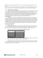
LED Indicators for the ProMedia-100:
LED
TX port FX port Description
PWR
Indicates unit is receiving DC power.
LINK
TP
Fiber
Steady ON when proper link is established at both ends of the media
segment, i.e., when both end’s connections are properly made and
when power is applied to the devices on both ends of the segment.
Agency Approvals:
115v 60 Hz power supply is UL Listed (UL 1310), CSA Certified
230v 50 Hz power supply is same, also TUV and GS approved
Emissions: Meets FCC Part 15 Class A, cUL, CE
Warranty: Five years, return to factory
Made in USA
ProMedia-100 Manual
Page 2
1.2
Ordering Information
Model Number Description
ProMedia-100SC
1-port 100Base-TX (RJ45) to 1-port 100Base-FX (multimode fiber SC),
external 115-volt, 60Hz or 230-volt, 50Hz power supply
ProMedia-100ST
1-port 100Base-TX (RJ45) to 1-port 100Base-FX (multimode fiber ST),
external 115-volt, 60Hz or 230-volt, 50Hz power supply
ProMedia-100SC-SM 1-port 100Base-TX (RJ45) to 1-port 100Base-FX (singlemode fiber SC),
external 115-volt, 60Hz or 230-volt, 50Hz power supply
ProMedia-100ST-SM 1-port 100Base-TX (RJ45) to 1-port 100Base-FX (singlemode fiber ST),
external 115-volt, 60Hz or 230-volt, 50Hz power supply
Waters Network Systems reserves the right to change specifications and/or model offerings
without notice.
2.0
INTRODUCTION
This section describes the ProMedia-100 Fast Ethernet media converters, including appearance,
features and possible applications.
2.1
Inspecting the Package and Product
Examine the shipping container for obvious damage prior to installing this product; notify the
carrier of any damage, which you believe occurred during shipment or delivery. Inspect the contents of
this package for any signs of damage and ensure that the items listed below are included.
This package should contain:
1 ProMedia-100 media converter unit
1 External Power Supply, either 115 vac 60 Hz or 230 vac 50 Hz
1 Set of two (2) metal mounting clips with screws
1 Velcro Tape section, approximately 3 inches in length
1 User Guide (this manual) and Product Registration Card
Remove the ProMedia-100 media converter from the shipping container. Be sure to keep the
shipping container should you need to ship the unit at a later date. To validate the product warranty
please complete and return the enclosed Product Registration Card to Waters Network Systems within
two weeks of purchase.
In the event there are items missing or damaged contact your supplier. If you need to return the
unit use the original shipping container. Refer to Section 5, Troubleshooting, for specific return
procedures.
2.2
Product Description
ProMedia-100 Fast Ethernet media converters offer a convenient and easy way to convert and
transmit data among twisted pair and fiber network cabling environments. They allow the use of fiber
media with full-duplex devices such as Fast Ethernet switching hubs (managed and unmanaged), and
may sometimes be used with shared (half-duplex) Fast Ethernet segments as well. They offer a
compact, cost-effective way to adapt a pre-existing Ethernet cabling configuration as network
requirements change.
ProMedia-100 media converters are designed for quick and easy installation even in very tight
spaces as media cables are easily attached. ProMedia-100 media converters feature an up-link switch on
the TX port to eliminate the need for a special crossover cable when connecting the TX port to a hub or
concentrator. Because of their compact size, ProMedia media converters can be Velcro®-mounted on an
office wall or the side of a desk or cabinet. The external power supply plugs into a nearby AC wall socket
ProMedia-100 Manual
Page 3
or power strip. Each converter features a full set of LEDs that convey essential diagnostic and status
information. See Section 4.1, LED Indicators, for specific LED function information.
ProMedia-100 media converters are designed to provide low-temperature operation over an
extended period to make them some of the most reliable in the industry. Their high-strength fabricated
metal packaging shields against Radio Frequency Interference (RFI) and Electromagnetic Interference
(EMI), avoiding interference with other nearby electronic devices.
The ProMedia-100 units comply with the IEEE 802.3u (100BASE-TX and 100BASE-FX)
specification for 100 Mbps traffic via shielded (STP) or unshielded twisted pair (UTP) segments.
The ProMedia-100ST (multimode) and –100ST-SM (singlemode) models are equipped with one
fiber-ST and one RJ45 connector for connection to 100BASE-FX compliant Fast Ethernet network
segments.
The ProMedia-100SC (multimode) and –100SC-SM (singlemode) are equipped with one fiber-SC
and one RJ45 connector for connection to 100BASE-FX compliant Fast Ethernet network segments.
2.3
Features and Benefits
Reduces Network Costs
ProMedia-100 media converters offer an ideal solution to quickly and inexpensively connect
Twisted-Pair TX with fiber FX segments.
Full-duplex or Half-duplex transparent operation
ProMedia-100s can be used in full-duplex fiber segments for distances up to 2Km for the
multimode model and up to 15km for the singlemode model.
Low PDV for Maximum Cable Lengths in Shared Segments
ProMedia-100 media converters add signal timing delays of only 80 Bit Times in a shared halfduplex segment, less than a Class II Fast Ethernet Repeater (90 to 95 BT typical), and can be
used to attach fiber cables to TX ports with minimum distance loss in the overall collision domain.
Small, Compact, Lightweight Design
Featuring a compact and lightweight metal case with an external power supply, ProMedia-100
media converters can be conveniently installed in minimal space, on horizontal or vertical
surfaces.
Full Complement of LEDs.
Each ProMedia-100 media converter is equipped with a full complement of LEDs to provide
network LINK status on each port separately, and to indicate power on the unit.
Highly Reliable and Dependable
ProMedia-100 media converters are based on a robust design and are packaged in a metal
enclosure to ensure high reliability and durability.
2.4
Applications
The primary function of a ProMedia-100 media converter is to permit two different media types to
coexist within the same network by allowing data to be transmitted and received between different media
types. ProMedia-100s are typically used where new 100Mbps switching hubs with RJ45 ports are being
installed, and where full-duplex fiber segments (of up to 2km for multimode or 15km for singlemode) are
needed to interconnect them with other 100Mbps switching hubs in distant wiring closets. Alternatively, a
server with a full-duplex NIC needs to be connected via fiber to a 100Mbps switching hub with RJ45
ports. In these and similar situations, the ProMedia-100 conveniently converts the twisted pair cable to
fiber, allowing use of any available RJ45 Fast Ethernet switched port with a new or existing fiber cable.
See Section 3.2.1 for cable distance calculation information.
Where shared Fast Ethernet segments are used, such as with Fast Ethernet hubs with RJ45
ports, it may be desirable to connect one or more servers or users via fiber cable. It is necessary to
calculate the PDV of the overall collision domain (see Section 3.2.2) for proper operation when the
ProMedia-100 is used in shared half-duplex applications.
ProMedia-100 Manual
Page 4
3.0
INSTALLATION
This section describes the installation of the ProMedia-100 media converters, including location,
segment distance calculation and media connection.
3.1
Locating the Media Converter Unit
The compact and lightweight design of the ProMedia-100 media converter allows it to be easily
installed in most any location. A Velcro strip and a set of two metal clips and screws are included (either
may be used) for mounting the unit on a vertical surface such as a wall or cabinet, or for securing the unit
on a tabletop or shelf. The installation location is dependent upon the physical layout of the Ethernet
network and associated cabling. Make sure the unit is installed in a location that is easily accessible to
an AC power outlet or power strip, and where convection cooling is not inhibited.
3.2
Calculating Segment Distances
The media distance considerations are quite different for full duplex and for half-duplex (standard
Fast Ethernet) installations. Each of these situations is covered below in a separate section.
3.2.1
Segment Distances, Full Duplex
Full-duplex ports, such as are found in switching hubs and some NICs, can receive and transmit
signals simultaneously and do not experience collisions accordingly. There may be only two nodes
present on a full-duplex segment. Media distance rules are not the same as for standard (half-duplex)
Fast Ethernet because collision distance limitations are not a factor. Specifically, fiber segments can be
up to 2km for multimode and up to 15km for singlemode.
The ProMedia-100, with full-duplex operation as a standard feature, can be used in these
applications. When installing the ProMedia-100 in a full-duplex segment, it is important to consider the
combined overall segment length of both of the attached media types. The overall segment length is
calculated by adding together the segment lengths on both sides of the ProMedia-100 media converters.
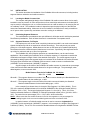
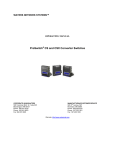
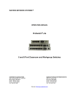
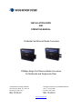
The figure below illustrates how a ProMedia media converter is used to connect a multimode fiber
(100BASE-FX) with a twisted pair (100BASE-T) segment.
Segment length on each side of the ProMedia-100 media converter is measured as a percentage
of the maximum allowable standard media distance for the given media type. The percentages, when
added together, must not exceed 100%.
Media Distance Formula for ProMedia-100, full-duplex:
X% + Y% < 100%
Where X = The segment distance on one side of the media converter divided by the Standard Maximum
Media Distance for that media type, x 100%
Where Y = The segment length on the other side of the media converter divided by the Standard
Maximum Media Distance for that media cabling type, x 100%
In the example figure shown above, the length of fiber Segment X is 1500m (4920 ft). This is
75% of the maximum allowable distance for multimode 100BASE-FX fiber full-duplex media (2000 m)
[75/2000 x 100% = 75%]. The length of twisted pair Segment Y is 10m (33 ft). This is 10% of the
maximum allowable distance for 100BASE-TX full-duplex twisted-pair media (100 m) [10/100 x 100% =
10%]. The total of the two percentages (75% + 10%) is 85%, which is allowable.
Note 1: Where more than one media converter is used in one segment run, the percentages for
all of the cabling lengths in the run must be added together and must not exceed 100%.
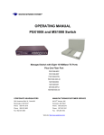
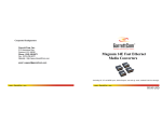
In another instance, a ProMedia media converter is used to connect a singlemode fiber
(100BASE-FX) with a twisted pair (100BASE-T) segment. In this example, the length of fiber Segment X
is 8500m (27,880 ft). This is 57% of the maximum allowable distance for singlemode 100BASE-FX fiber
ProMedia-100 Manual
Page 5
full-duplex media (15,000 m) [57/15,000 x 100% = 57%]. The length of twisted pair Segment Y is 12m
(40 ft).
This is 12% of the maximum allowable distance for 100BASE-TX full-duplex twisted-pair media (100 m)
[12/100 x 100% = 12%]. The total of the two percentages (57% + 12%) is 69%, which is allowable.
3.2.2
Segment Distances, Half duplex
Fast Ethernet shared bandwidth devices operate with multiple nodes in a traffic domain. When a
node attempts to send a packet, it may hit another packet passing by, i.e., a collision may occur. This is
normal and does not cause a problem because the Ethernet protocol provides for this situation and
requires that the sender waits and try again. When installing the ProMedia-100 in a half-duplex segment,
it is important to consider the collision domain of the segment, including the ProMedia-100 itself,
repeaters and hubs present, and the lengths of both of the attached media types.
Collision Domain
A collision domain is defined in the IEEE 802.3u standard as a cluster of network devices that,
regardless of topology, must be less than 512 BT (Bit Times) of signal delay (PDV or Path Delay Value)
in diameter between any two nodes. Nodes in a collision domain are connected by means of a repeater
or repeaters such that no bridging or switching devices are present between any two nodes in the cluster.
A ProMedia-100 has a PDV of about eighty Bit Times (80 BT), and this value must be included in the
overall collision domain diameter PDV calculations as applicable for the placement of the -100 in the
topology of the collision domain.
Collision Domain Diameter
The Collision Domain Diameter is the length of the longest path between any two devices in a
single collision domain. Regardless of the actual network topology, the Collision Domain Diameter must
be less than 512 BT (Bit Times). Bit Times are related to media type as shown in Table 3.2.2a.
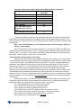
Table 3.2.2a: Worst case round-trip delay for Fast Ethernet media*
Media Type
Round-trip delay in Bit
Time per Meter (BT/m)
Fiber Optic
1.000
Shielded TP cable
1.112
Category 5 Cable
1.112
Category 4 Cable
1.140
Category 3 Cable
1.140
*Worst case delays taken from IEEE Std 802.3u-1995, actual delays may be less for a particular
cable. Contact your cable supplier for exact cable specifications.
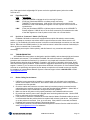
Each shared Fast Ethernet network device also has an associated BT delay. Table 3.4b shows
typical Fast Ethernet device components and the associated BT delay. Note that there is only one DTE
pair associated with any device-to-device path.
ProMedia-100 Manual
Page 6
Table 3.4b: Worst case round-trip delay for Fast Ethernet device components*
Component
Round-trip delay in Bit
Times (BT)
2 TX DTEs
100
2 FX DTEs
100
1 FX and 1 TX DTE
100
2 T4 DTEs
138
1 T4 and 1 TX or FX DTE
127
Class I Repeater
140
Class II Repeater with any
92
combination of TX and FX
ports
Class II Repeater with T4 ports
67
*Worst case delays taken from IEEE Std 802.3u-1995.
To determine whether a prospective network topology adheres to the collision domain diameter
specification, the following formula should be applied to the worst-case path through the network. The
worst-case path is the path between the two Fast Ethernet devices (DTEs), which have the longest round
trip delay time.
PDV = (sum of cabling delays) + (sum of repeater & media converter delays) + (DTE pair
delays) + (safety margin)
PDV is the Path Delay Value of the worst-case path. For the network to adhere to IEEE 802.3u
standard, this value must be less than 512 BT. The safety margin is specified in BT and may be a value
between 0 and 5. This margin can be used to accommodate unexpected delays, such as an extra long
patch cable. A safety margin of at least 4 BT is recommended.
“Rules-of-thumb” Collision Domain Calculations
Rules-of-thumb, while inexact, may be helpful in planning network topology. As a rule-of-thumb,
a Class II Repeater has a PDV of about 90 to 95 BTs, and twisted-pair or fiber media has a PDV of about
1 BT per meter of length. The ProMedia-100 has a PDV of 80 BT. Therefore, in shared Fast Ethernet
applications, the ProMedia-100 uses about 80 meters of equivalent cable distance to convert from TX
media to fiber FX media, i.e., it consumes almost as much of the available PDV as a Class II repeater.
Since a 512BT collision domain will almost always include at least one repeater and two media
segments, the remaining amount of Bit Times left after allowing for a ProMedia-100 and a length of fiber
media indicates that the available fiber length will be much less than the 412 meters that is the known
maximum for fiber. Therefore, in shared environments, ProMedia-100 media converters will be of benefit
when they allow the use of fiber media, but not to gain distance by facilitating use of fiber media instead
of twisted pair.
As a sample calculation, consider the question of what fiber cable distance (connected by a pair
of ProMedia-100s on each end) can be obtained that will interconnect two 100Mbps hubs where the
twisted pair cables to the user nodes are 10 meters in length. The solution is:
512 = total available Bit Times in a collision domain diameter,
minus 100 BT for two DTEs on each end leaves 412 BTs,
minus 180 BT for two Class II repeaters leaves 232 BTs,
minus 20 BT for two 10-meter TP cables for hubs to users leaves 212 BTs,
minus 10 BT for two short TP cables from the hubs to -100’s leaves 202 BTs,
minus 160 BT for two ProMedia-100s leaves 42 BTs for fiber cable,
which indicates a fiber cable length of about 40 meters.
ProMedia-100 Manual
Page 7
It is obvious that using twisted pair wiring to connect the hubs would enable the interconnect length to be
the 100 meters maximum for twisted pair media, and this would still leave about a hundred BTs as a
safety margin. In other words, use of ProMedia-100s and fiber in this case did not gain allowable
maximum cable distance vs. TP cable without the ProMedia-100s.
Consider a more typical use of ProMedia-100s in a shared Fast Ethernet segment. A stack of
Fast Ethernet hubs comprises the only repeater in the collision domain, and the users and servers in the
local workgroup are each connected via Category 5 twisted pair cable, a maximum of 30 meters (100 ft.)
in length. It is desired to connect one remote user with a fiber NIC via fiber cable, using a ProMedia-100
in the circuit. How long can the fiber cable be?
The solution is :
512 = total available Bit Times in a collision domain diameter,
minus 100 BT for two DTEs on each end leaves 412 BTs,
minus 90 BT for one Class II stackable repeater leaves 322 BTs,
minus 30 BT for one 30-meter TP cable from hub to user node leaves 292 BTs,
minus 5 BT for a short TP cable from the hub to -100 leaves 287 BTs,
minus 80 BT for one ProMedia-100 leaves 207 BTs for fiber cable,
which indicates a fiber cable length of about 200 meters.
3.3
Connecting Ethernet Media
Connecting Ethernet media to the ProMedia-100 media converter is very simple and
straightforward. Using a properly terminated media segment, simply attach the cable end to the
appropriate connector.
See Sections 4.2 and 4.3 for a description of the LEDs.
3.3.1
Connecting Twisted Pair (RJ45, standard and Link Pass-through models)
The following procedure describes how to connect a 100BASE-TX twisted pair segment to the
RJ45 port on the ProMedia-100 media converters. The procedure is the same for both unshielded and
shielded twisted pair segments.
1. Using standard 100BASE-TX media, insert either end of the cable with an RJ45 plug into the
RJ45 connector of the ProMedia-100 media converter.
2. Connect the other end of the cable to the corresponding device.
3. Use the LINK LED to ensure proper connectivity by noting that the LED will be illuminated when
the units are powered and proper connections established. If the LINK LED is not illuminated,
change the setting of the up-link switch If this does not help, ensure that the cable is connected
properly at both ends and is not defective.
3.3.2
Connecting Fiber Optic 100BASE-FX, Type ST and SC
The following procedure applies to 100BASE-FX applications using the ProMedia-100 media
converter with ST-type (twist-lock) and SC-type (snap-in) fiber connectors.
1. Before connecting the fiber optic cable, remove the protective dust caps from the tips of the
connectors on the ProMedia-100. Save these dust caps for future use.
2. Wipe the ends of the dual connectors clean with a soft cloth or lint-free lens tissue dampened in
alcohol. Make certain the connectors are clean before connecting.
Note: One strand of the duplex fiber optic cable is coded using color bands at regular
intervals; you must use the color-coded strand on the associated ports at each end of the
fiber optic segment.
3. Connect the Transmit (TX) port (light colored post) on the ProMedia-100 to the Receive (RX) port
of the remote device. Begin with the color-coded strand of the cable for this first “Transmit-toReceive” connection.
ProMedia-100 Manual
Page 8
4. Connect the Receive (RX) port (dark colored post) on the ProMedia-100 to the Transmit (TX) port
of the remote device. Use the non-color coded fiber strand for this.
5. The LINK LED corresponding to the fiber port, on the front of the product, will illuminate when a
proper connection has been established at both ends (and when power is ON in the units at each
end). If LINK is not lit after cable connection, the normal cause is improper cable polarity. Swap
the fiber cables on the product connector to remedy this situation.
3.3.3
Power Budget Calculations for Fiber Media
Receiver Sensitivity and Transmitter Power are the parameters necessary to compute the power
budget. To calculate the power budget of different fiber media installations, the following equations
should be used:
OPB (Optical Power Budget) = PT(min) - PR(min)
where PT = Transmitter Output Power, and PR = Receiver Sensitivity
Worst case OPB = OPB - 1dB(for LED aging) - 1dB(for insertion loss)
Worst case distance = {Worst case OPB, in dB} / [Cable Loss, in dB/Km]
where the “Cable Loss” for 62.5/125 and 50/125µm (m.m.) is 2.8 dB/km,
and the “Cable Loss” for 100/140 (multimode) is 3.3 dB/km,
and the “Cable Loss” for 9/125 (singlemode) is 0.5 dB/km
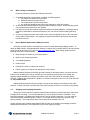
The following data has been collected from component manufacturer’s (HP’s and Siemens’) web sites
and catalogs to provide guidance to network designers and installers.
Fiber Speed,
Std. km Wave- Cable X’mitr R’cvr Worst Worst*
Port
Std. Mode
fdx
length
Size Output Sens. OPB,
dist.
Module
(hdx)
nm
µm
PT , dB PR ,dB
dB Km, fdx
100SC, 100Mb Multim
2
1300 62.5/125 -20
-31
9.0
2.5
100ST
FX
ode
(0.4)
50/125 -23.5
-31
5.5
2.0
SC-SM, 100Mb Single 18+
1300
9/125
-15
-31
14
28
ST-SM
FX mode (0.4)
typical typical*
OPB,
dist.
dB
Km, fdx
14
5
12
4
17.5
35
* Note: The use of either multimode or singlemode fiber to operate at 100Mbps speed over long
distances (i.e., over approx. 400 meters) can be achieved only if the following factors are both applied:
1. The 100Mb fiber segment must operate in full-duplex (FDX) mode, i.e. a switch (or equal external
unit such as a FDX NIC) must be used, and
2. The worst-case OPB of the fiber link must be greater than the fiber cable’s passive Attenuation.
(Attenuation = Cable loss + LED aging loss + Insertion loss + safety factor)
4.0
OPERATION
This section describes the operation of the ProMedia-100 media converters including power
supply requirements, up-link switch functionality, and a description of all LEDs.
4.1
Power Requirements, Power Supply Types
ProMedia-100 media converters require 5 watts of power and are designed to be used with an
external power supply. The external power supply unit supplied is one of two types; one version for AC
input power of 115-vac 60 Hz, and one version for 230-vac 50 Hz. The 115-vac version has a small
transformer integral with a convenience power outlet plug. The 230-vac version has a small transformer
integral with an IEC-type power plug for a user-supplied AC power cord with a convenience power outlet
ProMedia-100 Manual
Page 9
plug. Both types include a lightweight DC power cord to the applicable power jack on the media
converter unit.
4.2
Front Panel LEDs
Description
LED
PWR
Illuminates GREEN to indicate the unit is receiving DC power.
LINK
(RJ45 port) Illuminates GREEN, to indicate proper connectivity
on the
100BASE-TX network segment. LINK will turn off in the event connectivity is lost
between the ends of the twisted pair segment or a loss of power occurs in the unit or
remote device.
LINK
(Fiber port) Illuminates GREEN, to indicate proper connectivity on the 100BASE-FX
network segment. LINK will turn off in the event connectivity is lost between the ends
of the fiber segment or a loss of power occurs in the unit or remote device.
4.3
Up-Link or “Crossover” Switch (On TX port)
ProMedia-100 Media converters are equipped with an uplink slide switch to accommodate
switch- or repeater-to-converter connections without a special crossover cable. When set to the UP
position (=), the ProMedia-100 media converter is wired for normal twisted pair connection to a user node
device. When set to the DOWN position (X), the media converter is wired with crossover functionality for
direct up-link to a network hub or concentrator.
Switch ports may be of either polarity, and this feature is very convenient with switches
accordingly.
5.0
TROUBLESHOOTING
All ProMedia Ethernet products are designed to provide reliability and consistently high performance
in all network environments. The installation ProMedia-100 media converters is a straightforward
procedure and is described in Sections 3.0); operation is very simple and is described in Section 4.0.
Should problems develop during installation or operation, this section is intended to help locate, identify
and correct these types of problems. Please follow the suggestions listed below prior to contacting your
supplier. However, if you are unsure of the procedures described in this section or if the ProMedia media
converter is not performing as expected, do not attempt to repair the unit; instead contact your supplier
for assistance or contact Waters Network Systems’ customer support center at 800.328.2275 or email
[email protected].
5.1
Before Calling for Assistance
1. If difficulty is encountered when installing or operating the unit, refer back to the Installation
Section of the chapter of this manual. Also check to make sure that the various components of
the network are inter-operable.
2. Check the cables and connectors to ensure that they have been properly connected and the
cables/wires have not been crimped or in some way impaired during installation. (About 90% of
network downtime can be attributed to wiring and connector problems.)
3. Make sure that an AC power cord is properly attached to the ProMedia media converter.
4. Be certain that each AC power cord is plugged into a functioning electrical outlet. Use the PWR
LEDs to verify each unit is receiving power.
5. If the problem is isolated to a network device other than the Waters’ ProMedia media converter, it
is recommended that the problem device be replaced with a known good device. Verify whether
or not the problem is corrected. If not, go to next step. If the problem is corrected, the Waters’
ProMedia and its associated cables are functioning properly.
6. If the problem continues, contact Waters Network Systems Customer Service at 800.328.2275 or
email [email protected] for assistance.
ProMedia-100 Manual
Page 10
5.2
When Calling for Assistance
Please be prepared to provide the following information:
1. A complete description of the problem, including the following points:
a. The nature and duration of the problem.
b. Situations when the problem occurs.
c. The components involved in the problem.
d. Any particular application that, when used, appears to create the problem
2. An accurate list of Waters Network Systems product model(s) involved. Include the date(s) that
you purchased the products from your supplier.
3. It is useful to include other network equipment models and related hardware, including personal
computers, workstations, terminals and printers; plus, the various network media types being
used.
4. A record of changes that have been made to your network configuration prior to the occurrence
of the problem is also helpful. Any changes to system administration procedures should all be
noted in this record.
5.3
Return Material Authorization (RMA) Procedure
All returns for repair must be accompanied by a return material authorization (RMA) number. To
obtain an RMA number, call Waters Network Systems’ customer service at 800.328.2275 during business
hours of 8:00 am to 5:00 pm (CT) or email [email protected]. When calling, please have the
following information readily available:
Name and phone number of your contact person
Name of your company/institution
Your shipping address
Product name
Packing list number (or sales order number)
Failure symptoms, including a full description of the problem
Waters Network Systems will carefully test and evaluate all returned products, will repair products
that are under warranty at no charge, and will return the warranty-repaired units to the sender with
shipping charges prepaid (see warranty information at the end of this manual for complete details).
However, if Waters cannot duplicate the problem or condition causing the return, the unit will be returned
as: No problem found.
Waters Network Systems reserves the right to charge for the testing of non-defective units under
warranty. Testing and repair of product that is not under warranty will result in a customer (user) charge.
5.4
Shipping and Packaging Information
Should you need to ship the unit back to Waters Network Systems, please follow these instructions:
Package the unit carefully. It is recommended that you use the original container if available. Units
should be wrapped in a "bubble-wrap" plastic sheet or bag for shipping protection. (You may retain all
connectors and this installation guide.) Caution: Do not pack the unit in Styrofoam "popcorn" type
packing material. This material may cause electro-static shock damage to the unit.
Clearly mark the return material authorization (RMA) number on the outside of the shipping container.
Waters Network Systems is not responsible for your return shipping charges.
ProMedia-100 Manual
Page 11
Ship the package to:
Waters Network Systems
Attention: Customer Service
945 37th Avenue, NW
Rochester, MN 55901
6.0
Warranty Information
Waters Network Systems’
Warranty Statement
Waters Network Systems’ products are warranted against defects in materials and workmanship. The
warranty period for each product will be provided upon request at the time of purchase. Unless otherwise
stated, the warranty period is for the useable life of the product.
In the event of a malfunction or other indication of product failure attributable directly to faulty materials
and/or workmanship, Waters Network Systems will, at its option, repair or replace the defective products
or components at no additional charge as set for herein. This limited warranty does not include service to
repair damage resulting from accident, disaster, misuse, neglect, lightning, acts of God, tampering or
product modification.
Service under the warranty may be obtained by contacting Waters Network Systems and receiving a
Return Material Authorization (RMA) number from Waters Network Systems. Returned product
accompanied with the issued RMA number and prepaid shipping will be repaired or replaced by Waters
Network Systems. Repaired or replaced products will be returned at no cost to the original Buyer and
shipped via the carrier and method of delivery chosen by Waters Network Systems.
Specific warranty by product family is as follows:
ProSwitch-Secure:
ProSwitch-SecureAir+:
ProSwitch-Lite:
ProSwitch-Xpress:
ProSwitch-Xtreme:
ProSwitch-FlexPort:
ProSwitch-FixPort:
ProSwitch-CS and CSX:
ProMedia Converters
Limited Lifetime (see note)
Limited Lifetime
3 Years from date of manufacture (see note)
Limited Lifetime
Limited Lifetime (see note)
Limited Lifetime
Limited Lifetime
3 Years from date of manufacture (see note)
3 Years from date of manufacture (see note)
Note: Warranty period for any and all external power supplies is one (1) year from date of
purchase.
EXCEPT FOR THE EXPRESS WARRANTY SET FORTH ABOVE, WATERS NETWORK SYSTEMS GRANTS
NO OTHER WARRANTIES, EXPRESSED OR IMPLIED, BY STATUTE OR OTHERWISE, REGARDING
THE PRODUCTS, THEIR FITNESS FOR ANY PURPOSE, THEIR QUALITY, THEIR MERCHANTABILITY,
OR OTHERWISE.
WATERS NETWORK SYSTEMS’ LIABILITY UNDER THE WARRANTY SHALL BE LIMITED TO PRODUCT
REPAIR, OR REPLACEMENT OF THE BUYER’S PURCHASE PRICE. IN NO EVENT SHALL WATERS
NETWORK SYSTEMS BE LIABLE FOR THE COST OF PROCUREMENT OF SUBSTITUTE GOODS BY THE
CUSTOMER OR FOR ANY CONSEQENTIAL OR INCIDENTAL DAMAGES FOR BREACH OR
WARRANTY.
ProMedia-100 Manual
Page 12