1
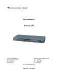
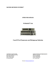
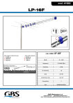
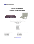
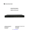
WATERS NETWORK SYSTEMS™ OPERATING MANUAL ProSwitch 16F CORPORATE HEADQUATERS 5001 American Blvd. W., Suite 605 Bloomington, MN 55437 Phone: 800.441.5319 Phone: 952.831.5603 Fax: 952.831.5605 MANUFACTURING/CUSTOMER SERVICE th 945 37 Avenue, NW Rochester, MN 55901 Phone: 800.328.2275 Phone: 507.252.1951 Fax: 507.285.1952 Web site: http://www.watersnet.com TABLE OF CONTENTS 1.0 SPECIFICATIONS ............................................................................................................................. 3 2.0 PACKAGE CONTENTS - PROSWITCH 16F .................................................................................. 5 2.1 PRODUCT DESCRIPTION................................................................................................................ 5 2.2 100BASE-FX FIBER MODULES....................................................................................................... 6 2.3 LOCATION OF THE 16F SWITCH.................................................................................................... 6 3.0 CONNECTING THE 16F.................................................................................................................... 7 3.1 MOUNTING THE 16F ........................................................................................................................ 7 3.2 POWERING THE 16F........................................................................................................................ 7 3.3 MODULE INSTALLATION ................................................................................................................ 8 4.0 STATUS OF LEDS .......................................................................................................................... 10 5.0 VLAN AND QOS.............................................................................................................................. 11 6.0 USING THE CONSOLE PORT........................................................................................................ 12 7.0 TROUBLESHOOTING..................................................................................................................... 18 7.1 BEFORE CALLING FOR ASSISTANCE ........................................................................................ 18 7.2 RETURN MATERIAL AUTHORIZATION (RMA) PROCEDURE.................................................... 19 7.3 SHIPPING AND PACKAGING INFORMATION ............................................................................. 19 12 ProSwitch 16F User’s Manual Page 2 1.0 SPECIFICATIONS OPERATIONAL CHARACTERISTICS: MAC Address Table: Filtering address Unicast/Multicast/Broadcast address 2k MAC addresses Performance: Store and forward architecture with non-blocking switching architectures Supports IEEE 802.3x full-duplex flow control Wire speed filtering and forwarding rate System aggregate forwarding rate: 14,880 pps for Ethernet 148,800 pps for Fast Ethernet RAM buffers: 256k bytes VLAN: 15 groups PORTS: Copper (RJ45) Ports: 10/100Mbps full/half duplex auto-negotiating switched ports 16 RJ45 ports (15 RJ45 ports if fiber module is used) Fiber (multimode or singlemode) slot: 100Base-FX slot, full/half duplex Console Port: RS232 MDI/MDI/X: Auto detect NETWORK STANDARDS: IEEE 802.3u: 100BASE-TX, 100BASE-FX Fast Ethernet IEEE 802.3: 10BASE-T Ethernet IEEE 802.3x Flow Control IEEE 802.1Q OPERATING ENVIRONMENT: Ambient: 32° to 122°F (0° to 50°C) Storage: -40° to 158°F (-40° to 70°C) Ambient relative humidity: 5% to 95% (non-condensing) LED INDICATORS: Power status for each unit per port: Link/Activity Duplex/Collision status for each TP port Link/Activity, 100, Duplex/Collision for each fiber slot NETWORK CABLE CONNECTORS: RJ45 shielded female ports (100m maximum) 100Mbps: CAT5 10Mbps: CAT3, 4 or 5 OPTIONAL FIBER PORT: Connectors for multimode FX – ST and SC (2km maximum) Connectors for singlemode FX – SC (20km) POWER SUPPLY (INTERNAL): AC Power Connector: IEC-type, male recessed, rear, ON/OFF switch Power Input Voltage: 100 to 240V Power Input Frequency: 50 to 60Hz Power Consumption: ProSwitch-16F – 16W MECHANICAL: Enclosure: Rugged high-strength sheet metal 19 inch 1U rack-mounting 12 ProSwitch 16F User’s Manual Page 3 Dimensions: 430 x 105 x 44mm Weight: Switch, 5.0 lbs; Fiber modules, 1.3 oz. AGENCY APPROVALS: UL 1950, CE Mark, CISPR 22 Class A Emissions meet FCC Part 15, Class A WARRANTY: Limited Lifetime Made in USA 12 ProSwitch 16F User’s Manual Page 4 Package Contents - ProSwitch 16F 2.0 Examine the shipping container for obvious damage prior to installing this product. Notify the carrier of any damage that you believe occurred during shipment. Ensure that the items listed below are included. The 16F package contains the following: 2.1 16F switch chassis AC power cord Two rack mounting kits and screws Console cable User’s manual Product Description A switch can be used to overcome the hub-to-hub connectivity limitations as well as improve overall network performance. Switches make intelligent decisions about where to send network traffic based on the destination address of the packet. As a result, the switch can significantly reduce unnecessary traffic. Figure 1 demonstrates the switch ability to segment the network. The number of nodes on each segment is reduced, thereby minimizing network collisions and boosting the available bandwidth per port. FS Another Ethernet Switch FS Hub/Switch Hub/Switch Power User Workgroup Workgroup Figure 1: 16F Connection to Other Devices The 16F is a 16-port 10/100Mbps Fast Ethernet switch with an optional fiber module. The 16F will auto detect 10/100Mbps speed, full/half duplex mode, and MDI/MDI-X connection. Console management is supported in the 16F. VLAN trunking and port configuration can be configured to provide flexible network management and configuration functions. The 16F supports four priority transmit queues per port and Ethernet packets up to 1522 bytes for QoS function for advanced network applications. 12 ProSwitch 16F User’s Manual Page 5 2.2 100Base-FX Fiber Modules Fiber modules are available in the following configurations: FM-100SC 1-port 100Base-FX multimode fiber module with SC connector FM-100ST 1-port 100Base-FX multimode fiber module with ST connector FM-100SMSC-20 1-port 100Base-FX 20km singlemode fiber module with SC connector Any of the modules listed above can be used to: Connect the switch to the backbone of your network Connect the switch to a classroom/workgroup hub or switch Connect the switch to a server or workstation with a fiber NIC 2.3 Location of the 16F Switch The 16F can be installed quickly and easily. However, for an installation with minimum impact on the existing network, please read the following information carefully. Installing the 16F involves three steps: 1. Choosing a location 2. Supplying power 3. Connecting the switch Consider the following criteria when selecting a location for the switch: Avoid dusty locations Avoid electromagnetic noisy areas, such as locations close to power transformers or radio transmitters Avoid temperatures below 32° to 122°F (0° to 50°C) Allow sufficient space for proper ventilation Allow a clear view of the front panel LED indicators Allow easy access to the front panel ports and the rear panel switches Your switch comes with two rack mounting brackets which can be used to mount the switch on an EIA 19” standard rack. Attach the brackets to the switch using the screws provided. Next, install the switch in the rack using the screws provided to attach the brackets to the rack. 12 ProSwitch 16F User’s Manual Page 6 3.0 Connecting the 16F The 16F switch has been designed to support all standard Ethernet media types within a single switch unit. The various media types supported along with the corresponding IEEE 802.3 and 802.3u standards and connector types are as follows: Fiber: IEEE Standard Media Type Max. Distance Connector Type 100Base-FX multimode fiber 2km (6,562 ft) SC or ST 100Base-FX singlemode fiber 20km (65,616 ft) SC 10Base-T CAT3, 4 or 5 100m (328 ft) RJ45 100Base-TX CAT5 or 5E 100m (328 ft) RJ45 Copper: NOTE: Since dual-speed ports are auto-sensing for both 10 and 100Mbps, it is recommended that high quality CAT5 cables (which work for both 10Mbps and 100Mbps) be used whenever possible in order to provide flexibility in a mixed-speed network. Because the switch supports auto MDI/MDI-X detection, normal straight through cables for both workstation connection and hub or switch connection can be used. All 16 ports are auto MDI/MDI-X, so you can use any of the 16 ports to connect a port on another hub or switch with straight through or crossover cables. 3.1 Mounting the 16F Table-Top or Shelf Mounting The 16F switch can be easily mounted on a table-top or any suitable horizontal surface. There are four rubber feet provided for stability so finished surfaces won’t be scratched. Rack Mount Installation Your switch comes with two rack mounting kits. You can use these brackets to mount the switch on an EIA standard 19" rack. Attach the brackets to the switch, using the screws provided. Next, install the switch in the rack using the screws provided to attach the brackets to the rack. When properly installed, the front-mounted LED status indicators should be in plain view and easy to read 3.2 Powering the 16F The 16F switch is equipped with a universal power supply that accepts AC input voltages from 100 to 240VAC and 50 to 60 Hz. To supply power to your switch: 1. Plug the connector of the power cord into the power port on the rear panel of your switch. 2. Plug the other end of the power cord into an AC wall outlet. 3. Set the power switch to ON and verify that the Power LED is lit. If it is not, check the following: The power switch is in the ON position. The power cord is properly connected to the wall outlet and to the power connection on the switch. The wall outlet is functional. 12 ProSwitch 16F User’s Manual Page 7 Note: Network cable segments can be connected or disconnected from the switch while the power is on, without interrupting the operation of the switch. 3.3 Module Installation Warning: Before installing a module into the 16F, you must disconnect the switch from the main power supply. There are three choices of modules for long distance fiber optic cable connection. Note: If you install a fiber module, the 16th copper port will be disabled and the FX port becomes the 16th port. Handling Modules The module can be easily damaged by electrostatic discharge. To prevent damage, please observe the following: Do not remove modules from their packaging until you are ready to install it into a switch. Do not touch any of the pins, connections or components on the modules. Handle the modules only by its edges and front panel. Always wear an anti-static wristband connected to a suitable grounding point. Always store or transport modules in appropriate anti-static packaging. Module Installation 1. Ensure that the switch is disconnected from the main power supply and that you are wearing an anti-static wristband connected to a suitable grounding point. 2. Place the switch on a flat surface. 3. Using a small cross-bladed screwdriver, remove the blank module plate from the front of the switch. Do not remove any other screws from the switch. 4. Keep the blanking plate and screws in a safe place. If you remove the module at any time, you must replace the blanking plate to prevent dust and debris from entering the switch and to aid the circulation of cooling air. 5. Hold the module so that the text on the front panel is oriented correctly, and insert it into the switch, ensuring the connectors are fully engaged. Tighten the two captive thumbscrews that secure the module in place. Module Port Figure 2: Module Installation 12 ProSwitch 16F User’s Manual Page 8 Connecting the Module 1. Remove the protective plastic covers from the fiber connectors on the module. 2. Plug the ST (or SC) connector on the fiber cable into the fiber socket on the module. 3. Connect the other end of the fiber optic segment to an appropriate device fitted with a 100Mbps adapter. 4. Check the LED indicators on the front of the switch to ensure that the module is operating correctly. 5. Power up the switch. Module Configuration If you install the 100Base-FX module, the module becomes Port 16. You must hard set Port 16 to 100Mbps, Full Duplex and disable the auto negotiation. Refer to Section 6.0 – Using the Console Port - Port Setup to configure Port 16 to work with the installed fiber module. Removing the Module 1. Ensure that the power supply and the backbone connection cables are disconnected from the switch. 2. Place the switch on a flat surface. Undo the two captive thumbscrews securing the module into the switch. Do not remove any other screws from the switch. 3. If you are not installing another module immediately, you must replace the blank module plate to ensure that dust and debris do not enter the switch, as well as to aid circulation of cooling air. 12 ProSwitch 16F User’s Manual Page 9 4.0 Status of LEDs LED STATUS CONDITION Power ON Switch is receiving power. Link / Act ON Port has established a valid link. Flashing Data packets being received or sent. Green The connection speed is 100Mbps. Yellow The connection speed is 10Mbps. ON The connection is Full Duplex. Flashing Packet collisions occurring. Low levels of collisions are part of normal Ethernet operation. FDX / Col 12 ProSwitch 16F User’s Manual Page 10 5.0 VLAN and QoS VLANs The VLAN setting of a switch divides the switch to several switching segments. VLANs are logical subgroups within a LAN that have been created through software rather than by moving network cables. A VLAN can combine user stations and network devices into a single unit regardless of their physical attachment within the LAN. The purpose of a VLAN is to isolate traffic within a segment of the LAN. Data cannot be sent or received on different VLANs. Broadcast packets cannot be transferred between VLANs. The VLAN function is often used for security applications. Here are two examples for VLAN applications. The first one is called Concentration VLAN setting. In this case, Port (1,16), (2,16), (3,16), (4,16), …, (13,16), (14,16), (15,16) are in different VLANs and Port 16 is the common port for uplink or Internet connection. But the data transfer between Port 1, 2, 3, 4, …, 13, 14, 15 are impossible for such configuration. Uplink / Internet Connection 16 1 2 3 ..... 13 14 15 Figure 3: Concentration VLAN Setting The second one is the default VLAN setting of the switch. All ports belong to the same VLAN and can communicate with each other. 1 2 3 ..... 13 14 15 16 Figure 4: Default VLAN Setting Note: Refer to Section 6.0 – Using the Console Port for VLAN configuration. QoS Ethernet packets can contain a tag with information about the packet. The tag contains VLAN and priority information for the packet. The 16F can process both tagged and untagged packets at ingress ports????. If there is tag in Ethernet packets, the packet will be transmitted according to the priority of the packet. There are four transmit queues for each port of the 16F. The switch can transfer packets according to the priority of the packet to meet the "Quality of Service" request in the network. Quality of service is important so data can be routed appropriately if multimedia data (voice, video, etc.) is being transferred over the network. Note: The QoS function is defined in the switch controller and is not configurable. 12 ProSwitch 16F User’s Manual Page 11 6.0 Using the Console Port Hardware setup 1. Connect the console port on the switch to the COM port on the PC using the console cable included with the switch. Software setup 1. Boot PC with MS Windows. 2. Load the Hyper Terminal (hypertrm.exe) program. The Hyper Terminal program can be found in the folder Accessories – Communications – Hyper Terminal from the Program menu. If you don’t have the Terminal program, install it from your MS Windows installation disk. 3. If the connection file has been created, cancel the new connection request and open the connection file. OR 4. If the connection file has not been created, follow the instructions on the screen to create a new connection named "SW16". a. Select COM port of PC b. Set COM port parameters: c. "Bits per second: 9600 Data Bits: 8 Parity Check: None Stop Bit: 1 Flow Control: None". Select OK. 5. Power on the Switch. It will take a few seconds to initialize the switch. 6. Type the default password, 1234 and press Enter. The default password is "1234" which can be changed in the console setting. 7. The Main Menu will be displayed if the password is correct. Note: If the console screen does not display, reboot the switch or close the terminal program and start again. 12 ProSwitch 16F User’s Manual Page 12 Configuring the 16F The commands listed below are used throughout the Console Menu. Use the commands to customize the ports for your switch. m: modify a: add d: delete q: quit this function. The "Save & Update (Y/N)" message will be displayed when you quit a function. Port Setup This function allows users to enable/disable auto-negotiation, flow control and auto-MDIX functions of the connection ports. If auto-negotiation is disabled, users can set the connection speed and full/half duplex of the connection ports. The default is set to enable auto-negotiation. 1. Press 1 and Enter to select Port Setup. The following menu will be displayed. 2. Press m to modify a port. 3. Enter the port number and press Enter. 4. Make the necessary changes. Use the values listed at the top of the chart on the screen to make your selections. 5. Press q to quit until you reach the prompt to save your changes. 6. Press y to save the changes. Configure VLAN Groups 1. Press 2 and Enter to select VLAN Setup from the Main Menu. Note: Before configuring VLANs, the trunking function must be disabled. Trunking is disabled by default. Once the VLAN setup is complete, you may enable the trunking function if you need trunking connection on the switch. 2. Press 1 and Enter to select Port Base Concentration Setup. (Refer to Section 5 for a definition of Concentration VLANs. 3. Press m to modify. 12 ProSwitch 16F User’s Manual Page 13 4. Select the common port for the Concentration VLAN and press Enter. The software will create a concentration VLAN configuration automatically. 5. Press q to quit. 6. Press y to save. 7. To configure VLAN groups, press 2 and Enter to select VLAN & PVID Setup. 8. Press 1 and Enter to select VLAN Setup to create VLAN groups. All of the connection ports are in the same VLAN group default. There are three commands for this function. 9. m: modify setting of VLAN group. Select the VLAN group and then the connection port. Select the operation - add or remove the port to/from the VLAN. a: add ports to VLAN. Select the VLAN group and then select the ports to add to the VLAN group. d: delete VLAN group. This function will delete one VLAN group. q: quit this function. The "Save & Update (Y/N)" message will be displayed. Use "PVID Setup" function to set the PVID of ports. 10. Configure the appropriate settings. 11. Return to Main Menu. After the VLAN groups setup is complete, set the PVID of ports to the VLAN ID of their VLAN group. If port overlapping occurs, assign the PVID of the overlapped port to the VLAN ID that it will use for packet transmitting VLAN grouping. If packets are set to tagged, there will be VLAN ID in the tag of packets. If packets are untagged, the switch will assign PVID to the packet as its VLAN ID, and the switch will check the VLAN group setting with the VLAN ID. If they belong to the same VLAN, the packets will be forwarded. If they belong to different VLANs, the packets will be filtered out. 12 ProSwitch 16F User’s Manual Page 14 Note: Because the 16F supports VLAN ID 0~15 only, the switch will use bit 0~3 of VLAN ID as its VLAN ID if the VLAN ID in tagged packets are larger than 15. You can use command "m" to set ports to tag or untagged and set PVID of ports. The output packets from a tag port will always be tagged packets. If packets are untagged, the tag will be added before these packets are transmitted. And the output packets from an untagged port will always be untagged packets. If tagged packets, the tag will be removed before these packets are transmitted. The tag or untagged setting depends on the network applications. If you are not sure about your network applications, you may set all of the packets to untagged. Many old network devices do not support long Ethernet packets with tag (tag is another 4 bytes added to normal Ethernet packets). Note: Data will only be forwarded to ports in the same VLAN group. Data will not be forwarded to ports in different VLAN groups. The factory default setting of the switch is all ports belong to the same VLAN group. Trunking Setup 1. Press 3 and Enter to select Trunk Setup. 2. The 16F supports two trunks and two ports per trunk maximum. Press m to enable or disable the appropriate trunk. 3. Return to Main Menu. Note: Before you enable the trunk, check the VLAN setting of the ports used for trunk. They must belong to the same VLAN group and have the same PVID and tag/untagged setting. If they are different, set them to the same configuration. Changing Password 1. Use 4 – Password Setup to change your password. 12 ProSwitch 16F User’s Manual Page 15 Advanced Setup There are three advanced functions that can be configured with the Advanced Setup menu. Port Locking The Port Locking function locks the other ports so that a user can access a network connection only through one port. The Port Locking function has two locking operations: Static Lock: If the "Switch Aging" function of the switch in "Broadcast Storm Filter" setup is set to disable, only the user that the switch learns first on that port can use this connection port. This lock is in effect even the user turns OFF that workstation. Dynamic Lock: If the "Switch Aging" setting is set to enable, another user with another MAC ID could be the "onlyone" user for the port after the last user is OFF and the MAC ID is aged out. Broadcast Storm Filter Use this function to enable/disable the aging and broadcast storm filtering on of the switch from this function. If the broadcast storm filtering function is enabled, the broadcast packets over the rising threshold within 50ms will be discarded. You can set three threshold levels (per port) for broadcast storm. 10% for all 100TX, 1% for not all 100TX 20% for all 100TX, 2% for not all 100TX 40% for all 100TX, 4% for not all 100TX 12 ProSwitch 16F User’s Manual Page 16 CoS (Class of Service) There are four transmit queues per port which support the CoS function. The function allows you to configure the CoS function. Global 1. Select 3 and press Enter to select CoS Setup. 2. Select 1 Global. TOS Over VLAN priority: If enabled, the priority information in TOS will be processed first, then the priority information in VLAN tag will be processed. If disabled, the priority information in VLAN tag will be processed first. Port-Base Priority: If enabled, all the packets received from this port will be always sent with the assigned priority and the priority information in VLAN tag and TOS will be ignored. Port Priority Queue: Assign the transmit priority of packets received from the port if "Port-Base Priority" is enabled. VLAN/TOS Priority Map Use this function to map the priority value in VLAN/TOS to the four transmit queues. There can be eight priority values in VLAN tag and TOS, and these values will be mapped to the four transmit queues in each port. Use this function to configure the mapping. Restore Default Setup Use this function to restore the configuration to the default setting. Exit Use Exit to return to the login screen. 12 ProSwitch 16F User’s Manual Page 17 7.0 Troubleshooting All Waters’ switching products are designed to provide reliability and consistently high performance in all network environments. The installation of Waters’ ProSwitch 16F switch is a straightforward procedure (See Section 3); the operation is also straightforward and is discussed in Section 4. Should problems develop during installation or operation, this section is intended to help locate, identify and correct these types of problems. Please follow the suggestions listed below prior to contacting your supplier. However, if you are unsure of the procedures described in this section or if the Waters’ ProSwitch 16F switch is not performing as expected, do not attempt to repair the unit; instead contact your supplier for assistance or contact Waters Network Systems’ Customer Support Center at 800.328.2275 or email [email protected]. 7.1 1. 2. 3. 4. 5. 6. Before Calling for Assistance If difficulty is encountered when installing or operating the unit, refer back to the Installation Section of the chapter of this manual. Also check to make sure that the various components of the network are inter-operable. Check the cables and connectors to ensure that they have been properly connected and the cables/wires have not been crimped or in some way impaired during installation. (About 90% of network downtime can be attributed to wiring and connector problems.) Make sure that an AC power cord is properly attached to the ProSwitch 16F. Be certain that each AC power cord is plugged into a functioning electrical outlet. Use the PWR LEDs to verify each unit is receiving power. If the problem is isolated to a network device other than the Waters’ ProSwitch 16F switch, it is recommended that the problem device be replaced with a known good device. Verify whether or not the problem is corrected. If not, go to next step. If the problem is corrected, the Waters’ ProSwitch 16F switch and its associated cables are functioning properly. If the problem continues, contact Waters Network Systems Customer Service at 800.328.2275 or email [email protected] for assistance. When Calling for Assistance Please be prepared to provide the following information. 1. A complete description of the problem, including the following points: a. The nature and duration of the problem b. Situations when the problem occurs c. The components involved in the problem d. Any particular application that, when used, appears to create the problem 2. An accurate list of Waters Network Systems product model(s) involved. Include the date(s) that you purchased the products from your supplier. 3. It is useful to include other network equipment models and related hardware, including personal computers, workstations, terminals and printers; plus, the various network media types being used. 4. A record of changes that have been made to your network configuration prior to the occurrence of the problem. Any changes to system administration procedures should all be noted in this record. 12 ProSwitch 16F User’s Manual Page 18 7.2 Return Material Authorization (RMA) Procedure All returns for repair must be accompanied by a Return Material Authorization (RMA) number. To obtain an RMA number, call Waters Network Systems Customer Service at 800.328.2275 during business hours in 8:00 am to 5:00 pm (CT) email [email protected]. When calling, please have the following information readily available: Name and phone number of your contact person Name of your company/institution Your shipping address Product name Packing List Number (or Sales Order Number) Failure symptoms, including a full description of the problem Waters Network Systems will carefully test and evaluate all returned products, will repair products that are under warranty at no charge, and will return the warranty-repaired units to the sender with shipping charges prepaid (see Warranty Information, Appendix A, for complete details). However, if Waters cannot duplicate the problem or condition causing the return, the unit will be returned as: No Problem Found. Waters Network Systems reserves the right to charge for the testing of non-defective units under warranty. Testing and repair of product that is not under warranty will result in a customer (user) charge. 7.3 Shipping and Packaging Information Should you need to ship the unit back to Waters Network Systems, please follow these instructions: Package the unit carefully. It is recommended that you use the original container if available. Units should be wrapped in a "bubblewrap" plastic sheet or bag for shipping protection. (You may retain all connectors and this Installation Guide.) CAUTION: Do not pack the unit in Styrofoam "popcorn" type packing material. This material may cause electro-static shock damage to the unit. Clearly mark the Return Material Authorization (RMA) number on the outside of the shipping container. Waters Network Systems is not responsible for your return shipping charges. Ship the package to: Waters Network Systems Attention: Customer Service th 945 37 Avenue, NW Rochester, MN 55901 12 ProSwitch 16F User’s Manual Page 19 Limited Lifetime Warranty Waters Network Systems warrants to the original consumer or purchaser that each of it's products, and all components thereof, will be free from defects in material and/or workmanship for the lifetime of the product. Any warranty hereunder is extended to the original consumer or purchaser and is not assignable. Waters Network Systems makes no express or implied warranties including, but not limited to, any implied warranty of merchantability or fitness for a particular purpose, except as expressly set forth in this warranty. In no event shall Waters Network Systems be liable for incidental or consequential damages, costs, or expenses arising out of or in connection with the performance of the product delivered hereunder. Waters Network Systems will in no case cover damages arising out of the product being used in a negligent fashion or manner. 12 ProSwitch 16F User’s Manual Page 20