1
WATERS NETWORK SYSTEMS™
OPERATING MANUAL
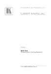
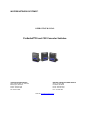
ProSwitch CS and CSX Converter Switches
CORPORATE HEADQUATERS
5001 American Blvd. W., Suite 605
Bloomington, MN 55437
Phone: 800.441.5319
Phone: 952.831.5603
Fax: 952.831.5605
MANUFACTURING/CUSTOMER SERVICE
th
945 37 Avenue, NW
Rochester, MN 55901
Phone: 800.328.2275
Phone: 507.252.1951
Fax: 507.285.1952
Web site: http://www.watersnet.com
TABLE OF CONTENTS
1.0
2.0
2.1
2.2
2.3
2.4
2.5
3.0
3.1
3.2
3.21
3.22
3.23
3.24
3.25
3.26
3.3
3.31
3.32
3.4
4.0
4.1
4.2
4.3
4.4
4.5
5.0
6.0
6.1
6.2
6.3
7.0
SPECIFICATIONS ......................................................................................................................... 3
PACKAGE CONTENTS - PROSWITCH CONVERTER SWITCH ............................................. 5
PRODUCT DESCRIPTION ............................................................................................................ 5
OPERATION OF CS SERIES........................................................................................................ 5
FRAME BUFFERING AND LATENCY.......................................................................................... 6
FEATURES AND BENEFITS ........................................................................................................ 6
CONVERTER SWITCH APPLICATIONS..................................................................................... 7
INSTALLATION ............................................................................................................................. 8
LOCATION OF THE PROSWITCH CONVERTER SWITCH ........................................................ 8
CONNECTING THE PROSWITCH CONVERTER SWITCH TO YOUR NETWORK ................... 8
CONNECTING COPPER CABLES ............................................................................................... 9
CONNECTING FIBER ST CONNECTORS ................................................................................... 9
CONNECTING FIBER SC CONNECTORS................................................................................. 10
CONNECTING SINGLE-MODE FIBER OPTIC........................................................................... 10
POWER BUDGET CONSIDERATIONS...................................................................................... 10
CONNECTIONS TO RJ45 PORTS WITH AUTO-NEGOTIATION.............................................. 11
MOUNTING THE PROSWITCH CONVERTER SWITCH ........................................................... 11
RACK MOUNT ............................................................................................................................. 11
DIN-RAIL MOUNTING OPTIONS................................................................................................ 12
POWER REQUIREMENTS.......................................................................................................... 12
OPERATION ................................................................................................................................ 12
DUAL-SPEED FUNCTIONALITY AND SWITCHING ................................................................. 12
SWITCHING, FILTERING AND FORWARDING ........................................................................ 12
SWITCHING, ADDRESS LEARNING ......................................................................................... 13
AUTO-CROSS (MDIX), AUTO-NEGOTIATION AND SPEED-SENSING .................................. 13
(F- H) SWITCH, FULL-DUPLEX OR HALF-DUPLEX OPTIONS FOR FIBER PORT# 1........... 13
STATUS OF LEDS....................................................................................................................... 13
TROUBLESHOOTING................................................................................................................. 14
BEFORE CALLING FOR ASSISTANCE .................................................................................... 14
RETURN MATERIAL AUTHORIZATION (RMA) PROCEDURE................................................ 15
SHIPPING AND PACKAGING INFORMATION.......................................................................... 15
WARRANTY................................................................................................................................. 16
2
ProSwitch Converter Switch User’s Manual
Page 2
1.0
SPECIFICATIONS
PERFORMANCE:
100Mbps HDX/FDX, all types of connectors MM and SM
10Base-T, 100Base-TX and 100Base-FX
Auto-negotiation and auto-cross MDI-MDIX on RJ45 ports
Non-blocking switching
Packet buffer memory: 128KB
Address buffer storage: 2K
Fiber port has manual selection of HDX/FDX
LED INDICATORS:
Power-on
Separate link and port activity status for
each port
NETWORK STANDARDS:
IEEE 802.3
IEEE 802.3u
IEEE 802.1p
VLAN Support:
Tagged VLAN fields transmitted and unchanged by converter switch (IEEE 802.1q)
FIBER CABLE DISTANCES:
MM Fiber: 2km
SM Fiber: ST and SC connector, 20km/SC connector, 40km
NETWORK CABLE CONNECTORS:
RJ45 shielded female ports:
100Mbps: Category 5 UTP/STP
10Mbps: Category 3, 4, 5 UTP
Fiber MM port connectors:
MTRJ, SC, ST
Fiber SM port connectors:
SC, ST
EMI/SAFETY COMPLIANCE:
All Models:
UL Listed (UL60950), cUL, CE
Emissions meet FCC Part 15, Class A
2
ProSwitch Converter Switch User’s Manual
Page 3
CSX Series:
NEBS L3 and ETSI compliant
NEMA TS-2 and TEES for traffic control equipment
UL2043 for above ceiling installations
IEC61850 EMC and Operating Conditions for Class C Power Substations
POWER SUPPLY:
CS Series: External AC/DC, 95-125VAC@60Hz
CSX Series: External AC/DC, 95-260VAC@47-63Hz
OPERATING ENVIRONMENT:
Ambient:
Standard Converter Switch: 32° to 105°F (0° to 40°C)
Hardened Converter Switch: -40° to 167°F (-40° to 75°C)
Ambient Relative Humidity: All models: 5% to 95% (non-condensing)
Storage temperature: All models -40° to 185°F (-40° to 85°C)
PHYSICAL CHARACTERISTICS:
Ruggedized steel enclosure
Dimensions:
3.5”H x 3.0”W x 1.0”D (8.9cm x 7.6cm x 2.5cm)
Weight:
CS and CSX series: 4.6oz (130g)
Power supply CS series: 5.8oz (165g)
Power supply CSX series: 7.9oz (225g)
Altitude:
All models: -200 to 50,000 ft (-60 m to 15,000 m)
WARRANTY:
3 years (1 year on power supplies)
Made in USA
2
ProSwitch Converter Switch User’s Manual
Page 4
2.0 Package Contents - ProSwitch Converter Switch
Examine the shipping container for obvious damage prior to installing this product. Notify the carrier of any damage
that you believe occurred during shipment. Ensure that the items listed below are included.
The ProSwitch converter switch package contains the following:
2.1
CS or CSX converter switch
External power supply
One set metal panel mounting clips and screws (2 each)
User’s Guide
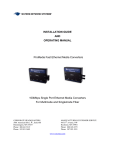
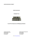
Product Description
Combine a 100Base-FX fiber media converter and a two-port 10/100Base-TX switch, and you have the converter
switch, a flexible edge-of-the-network Ethernet product. The CS and CSX models provide multi and singlemode fiber
port choices.
Converter switch models are available in a full range of application environments. CS models can be used for
standard (office) applications and CSX models are hardened models which can be used for a variety of factory floor
and outdoor applications. Extended temperature operation ranges are provided for the CSX models. If your
application requires a media converter, the converter switch offers a better value. The compact package is ideal for
network edge installations and can be conveniently mounted to suit any application.
The CS models can be used for office and indoor wiring closet environments. The ambient temperature rating is 32°
to 105°F and 0° to 40°C. A robust metal case with convection cooling is featured. Metal mounting clips are included,
and rack-mount tray options are available.
The CSX models are constructed using special thermal techniques and a heavy-duty metal case. They can be used
for factory floor applications as well as uncontrolled temperature applications. The ambient temperature rating of -40°
to 167°F and -40° to 75°C is ideal for industrial use. No internal air flow is required for cooling, so the unit resists
dust, dirt, moisture, smoke and insects. Mounting options include stand-alone panel-mounting, DIN-Rail, or rackmount tray. When used outdoors, the CSX should be protected from falling rain.
The CS and CSX models provide switching between two 10/100Base-TX auto-negotiating copper ports and one
100Base-FX ST, SC or MTRJ fiber port. Singlemode ports are available in SC or ST. The plug-and-play, energyefficient, and flavor rich fiber features make this sleek multi-purpose switch convenient and cost-effective for the user.
The selection of various temperature ranges enable easy deployment in various environments and qualify the
converter switch as a flexible option, which provides multiple solutions using very small space. Providing the
combination of media converter with switch, the CS Series is an ideal choice for edge-of–the-network applications.
2.2
Operation of CS Series
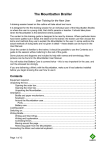
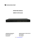
The front side of the unit has two twisted-pair 10/100Base-TX switch ports and one 100Base-FX fiber port. Both the
RJ45 ports of the CS Series support auto-cross (MDIX) operation performing the auto-cross function under autonegotiation mode only. The 100Base-FX models are factory set for full duplex by default.
There are two sets of LEDs indicating the operating status of ports. These LEDs are mounted on the top and front
(for extra viewing advantage while rack-mounted) of the converter switch. For each port, there are Link and Activity
(LK/ACT) LED’s on the top indicating that the media cables are connected correctly. When there is traffic, these
LEDs will be blinking. The LK/ACT LED’s are repeated on the front as LA1 (port 1), LA2 (port 2), and LA3 (port 3).
There is a power (PWR) indicator on the front of the unit to confirm that the unit is turned ON.
2
ProSwitch Converter Switch User’s Manual
Page 5
The full duplex/half duplex (F- H) manual switch provided below the fiber port allows the user to set the fiber port to
full or half duplex mode as required.
2.3
Frame Buffering and Latency
The CS converter switches are store-and-forward switches. Each frame (or packet) is loaded into the switch’s
memory and inspected before forwarding can occur. This technique ensures that all forwarded frames are of a valid
length and have the correct CRC, i.e. they are good packets. This eliminates propagation of bad packets, enabling all
of the available bandwidth to be used for valid information.
While other switching technologies such as "cut-through" or "express" impose minimal frame latency, they will also
permit bad frames to propagate out to the Ethernet segments connected. The "cut-through" technique permits
collision fragment frames, which are a result of late collisions, to be forwarded to add to the network traffic. Since
there is no way to filter frames with a bad CRC (the entire frame must be present in order for CRC to be calculated),
the result of indiscriminate cut-through forwarding is greater traffic congestion, especially at peak activity. Since
collisions and bad packets are more likely when traffic is heavy, the result of store-and-forward operation is that more
bandwidth is available for good packets when the traffic load is greatest.
To minimize the possibility of dropping frames on congested ports, each CS converter dynamically allocates buffer
space from 128Kb memory pool, ensuring that heavily used ports receive very large buffer space for packet storage.
Many other switches divide their packet buffer storage space evenly across all ports, resulting in a small, fixed
number of packets to be stored per port. When the port buffer fills up, dropped packets result. This dynamic buffer
allocation provides the capability for the maximum resources of the CS converter switches to be applied to all traffic
loads, even when the traffic activity is unbalanced across the ports. Since the traffic on an operating network is
constantly varying in packet density per port and in aggregate density, the CS converter switches are constantly
adapting internally to provide maximum network performance with the least dropped packets.
When the switch detects that its free buffer queue space is low, the switch sends industry standard (full-duplex only)
PAUSE packets out to the devices sending packets to cause “flow control”. This tells the sending devices to
temporarily stop sending traffic, which allows a traffic catch-up to occur without dropping packets. Then, normal
packet buffering and processing resumes. This flow-control sequence occurs in a small fraction of a second and is
transparent to an observer.
Another feature implemented in CS Series converter switches is a collision-based flow-control mechanism (when
operating at half-duplex only). When the switch detects that its free buffer queue space is low, the switch prevents
more frames from entering by forcing a collision signal on all receiving half-duplex ports in order to stop incoming
traffic.
The latency (the time the frame spends in the switch before it is sent along or forwarded to its destination) of the CS
Series converter switches varies with the port-speed types. The length of the frame is a variable as it is with all storeand-forward switches. For 10 to 100Mbps or 100 to 10Mbps forwarding, the latency is 15 microseconds plus the
packet time at 10Mbps. For 100 to 100Mbps forwarding, the latency is 5 microseconds plus the packet time at
100Mbps.
2.4
Features and Benefits
Full 10/100Mbps services for high performance Ethernet LANs
The CS converter switches provide Fast Ethernet switching on all ports. They perform high speed filter/forward
operations on the traffic, providing each port’s segment a full 10 or 100Mbps of bandwidth.
Reduces network costs and provide economical solution
2
ProSwitch Converter Switch User’s Manual
Page 6
Converter switches offer the ideal solution to efficiently and inexpensively connect a copper and fiber network with 10
or 100Mbps.
More efficient than media converter
Designed as a multi-purpose media converter and switch, the 100Mbps fiber port allows the user to convert media
from copper to fiber. The second RJ45 port can be used as diagnostic port or for additional device connectivity.
Installation is “Plug and Play” and operation is transparent to software
The CS Series switches operate as hardware switches, only forwarding those packets from each domain that are
required on the other domains. Internal address tables are self-learning, enabling users to change port connections
or 10/100 domains without affecting operations.
Two sets of LEDs for viewing status from any angle.
Each converter switch is equipped with two sets (front and top) of LEDs to provide status information when viewed at
almost any angle or mounting arrangement whether rack or wall-mounted.
Rugged metal case, industrial grade
The CS standard converter switch and are packaged in a rugged sheet metal enclosure to ensure high reliability and
durability even when placed in industrial or outdoor applications.
Qualified to use for temperature un-controlled “outdoor” application
The CSX series of converters switches are rated between -40° to 167°F and -40° to 75°C and qualify for temperature
un-controlled “outdoor” application.
Efficient compact design, for all purpose convenient mounting
Featuring a compact steel case with an external AC power supply, the CS converter switches can be installed in small
spaces in cabinets, on table tops, in racks, wall or DIN rail mounted and in trays.
MDIX ports to eliminate cross-over cable while cascading
No cross over cables are required since all converter switches provide MDIX (auto-cross), which easily allows
cascading with other switches, hubs or media converters.
2.5
Converter Switch Applications
Enriched with your choice of hardness ratings, the CS Series converter switches fit very well in almost any
environment enabling users to scale their networks quickly and cost effectively. The edge-of-the-network connectivity
solutions offered by the CS Series are focused on providing easier, economical and ultra-reliable industrial application
products. The compact converter switches act as very useful tools in the modern life of fast expanding network
requirements. The dual speed and dual media functions support a mixed environment of 10 and 100Mbps users with
copper and fiber media. The switched full / half duplex capability on fiber ports provides high bandwidth performance.
The 100Mbps fiber port enables easy expansion for the on-going demand of Ethernet networks. The 10/100Mbps
auto-negotiating copper ports together with the 100Mbps fiber port, enable easy interfacing with existing cable plant
and equipment.
The CSX converter switches fit very well in high temperature locations experiencing a need to scale the LAN quickly
and cost effectively. With its half / full duplex switching capability on fiber port # 1, the CSX models provide a very
economical high bandwidth solution for each port and also easily solve long distance requirements. The ruggedness
of the CSX’s steel case and the high reliability of the design compliments the temperature controlled packaging to
provide an exceptional Ethernet product.
2
ProSwitch Converter Switch User’s Manual
Page 7
3.0
Installation
This section describes the installation of the CS Series converter switches, including location, mountings, power
supply options and media connection.
The compact and lightweight design of the converter switch allows it to be easily installed in almost any location. A
Velcro strip may be used for mounting the unit on a vertical surface such as a wall or cabinet, or for securing the unit
on a table-top or shelf. Alternatively, metal mounting clips and screws are included for a rugged and secure mounting
in any orientation.
Installation of the CS converter switches is a simple procedure. The installation location is dependent upon the
physical layout of the Ethernet network and associated cabling. Make sure the unit is installed in a location that is
easily accessible to an AC power outlet and where cooling is not inhibited. The green Power (PWR) LED must turn
ON when power is applied.
3.1
Location of the ProSwitch Converter Switch
The converter switch can be installed quickly and easily. However, for an installation with minimum impact on the
existing network, please read the following information carefully. Installing the ProSwitch converter switch involves
three steps:
1.
Choosing a location
2.
Supplying power
3.
Connecting the fiber and copper ports.
Consider the following criteria when selecting a location for the switch:
Avoid dusty locations
Avoid electromagnetic noisy areas, such as locations close to power transformers or radio transmitters
Avoid temperatures below 32° and above 105°F (0° to 40°C) for CS models and below -40 and above 167°F
(-40° to 75°C) for CSX models.
Allow sufficient space for proper ventilation
Allow a clear view of the front panel LED indicators
Allow easy access to the front panel ports and the rear panel switches
The power outlet should be within six feet (1.8m) of the switch
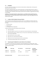
3.2
Connecting the ProSwitch Converter Switch to Your Network
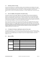
The ProSwitch converter switch has been designed to support all standard Ethernet media types within a single
switch unit. The various media types supported along with the corresponding IEEE 802.3 and 802.3u standards and
connector types are as follows:
Fiber:
Speed
Media Type
Max. Distance
Connector Type
100Base-FX
Multimode fiber
2km
SC, ST or MTRJ
Port Speed
Half/Full Duplex
100/200Mbps
100Base-FX
Singlemode fiber
20 or 40km
SC or ST
100/200Mbps
2
ProSwitch Converter Switch User’s Manual
Page 8
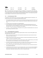
Copper:
10Base-T
CAT3, 4 or 5
100m (328ft)
RJ45
10/20Mbps
100Base-TX
CAT5 or 5E
100m (328ft)
RJ45
100/200Mbps
Note: Since all switch ports are auto-sensing for both 10 and 100Mbps, it is recommended that high quality CAT5
cables or above (which work for both 10Mbps and 100Mbps) be used whenever possible in order to provide flexibility
in a mixed-speed network. Because the switch supports auto MDI/MDI-X detection, normal straight through cables
for both workstation connection and hub or switch connection can be used.
3.21
Connecting Copper Cables
The following procedure describes how to connect the 10/100Base-TX twisted pair segment to the RJ45 port. The
procedure is the same for both unshielded and shielded twisted pair cables.
1.
Using standard twisted pair media, insert either end of the cable with a RJ45 plug into the RJ45 connector of the
port. Note that, even though the connector is shielded, either unshielded or shielded cables and wiring may be
used.
2.
Connect the other end of the cable to the corresponding device.
3.
Use the LINK LED to ensure proper connectivity by noting that the LED will be illuminated when the unit is
powered and proper connection is established. If this does not help, ensure that the cable is connected properly
and that the device on the other end is powered and is not defective.
4.
For Port # 1 or 1SW, if the LINK LED is not illuminated, move the position of the switch which has a cross-over or
uplink for linking to another hub or switch.
3.22
Connecting Fiber ST Connectors
Use the following procedure for installations using ST (twist-lock) fiber connectors. This procedure applies to ports
using multimode ST fiber connectors.
1.
Before connecting the fiber optic cable, remove the protective dust caps from the tips of the fiber connectors.
Save these dust caps for future use.
2.
Wipe the ends of the dual connectors clean with a soft cloth or lint-free lens tissue dampened in alcohol. Make
certain the connectors are clean before connecting.
Note: One strand of the duplex fiber optic cable is coded using color bands at regular intervals; you must use the
color-coded strand on the associated ports at each end of the fiber optic segment.
3.
Connect the Transmit (TX) port (light colored post) on the CS fiber port to the Receive (RX) port of the remote
device. Begin with the color-coded strand of the cable for this first TX-to-RX connection.
4.
Connect the Receive (RX) port (dark colored post) to the Transmit (TX) port of the remote device. Use the noncolor coded fiber strand for this.
5.
The LINK LED on the front of the fiber connector will illuminate when a proper connection has been established
at both ends (and when power is ON). If LINK is not lit after cable connection, the normal cause is improper
cable polarity. Swap the fiber cables at the fiber connector to remedy this situation.
2
ProSwitch Converter Switch User’s Manual
Page 9
3.23
Connecting Fiber SC Connectors
The following procedure applies to installations using SC (snap-in) fiber connectors. This procedure applies to
multimode and singlemode SC connectors.
1.
Snap on the two square male connectors into the SC female jacks of the Fiber connector until it clicks and
secures.
3.24
Connecting Single-Mode Fiber Optic
When using singlemode fiber cable, be sure to use singlemode fiber port connectors. Singlemode fiber cable has a
smaller diameter than multimode fiber cable (9/125 microns for single-mode, 50/125 or 62.5/125 microns for multimode where xx/xx are the diameters of the core and the core plus the cladding respectively). Singlemode fiber allows
full bandwidth at longer distances, (20 - 40km).
The same procedures as for multimode fiber apply to singlemode fiber connectors. Follow the steps listed in above.
3.25
Power Budget Considerations
Receiver sensitivity and transmitter power are the required parameters for the power budget calculation. To calculate
the power budget for fiber media installations using the CS products, use the following formulas:
OPB (Optical Power Budget) = PT(min) - PR(min)
PT = Transmitter Output Power, and PR = Receiver Sensitivity
Worst case OPB = OPB - 1dB(for LED aging) - 1dB(for insertion loss)
Worst case distance = {Worst case OPB, in dB} / [Cable Loss, in dB/Km]
“Cable Loss” for 62.5/125 and 50/125µm (MM.) is 2.8 dB/km,
“Cable Loss” for 100/140 (MM) is 3.3 dB/km,
“Cable Loss” for 9/125 (SM) is 0.5 dB/km
2
ProSwitch Converter Switch User’s Manual
Page 10
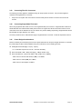
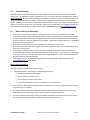
The following data has been collected from component manufacturer’s (HP’s, and Siemens’) web sites and catalogs
to provide guidance to network designers and installers:
Model
Speed Mode Std. Wave Cable X’mitr R’cvr Worst Worst*
km Length Size Output Sens. OPB, Distance
FDX
nm
km, FDX
µm PT , dB PR ,dB dB
(HDX)
Typical Typical*
OPB, Distance
dB
km, FDX
CS2TX1ST/SC 100Base- MM
FX
CSX2TX1
ST/SC
2
(0.4)
1300
62.5/1 -20
25
-23.5
50/125
-31
-31
9.0
5.5
2.5
2.0
14
12
5
4
CS2TX1MTRJ 100Base- MM
FX
CSX2TX
1MTRJ
100Base- SM
CS2TX1SSC/S
FX
ST-20
2
(0.4)
1300
62.5/1 -20
25
-23.5
50/125
-31
-31
9.0
5.5
3.0
2.0
15.8
12.2
5.5
4.0
20
(0.4)
1300
9/125
-15
-31
14
28
17.5
35
40
(0.4)
1300
9/125
-5
-34
27
54
32.5
65
CSX2TX1
SSC/SST
CS2TX1SSC40
100Base- SM
FX
CSX2TX1SSC40SC
Note: The use of either multimode or singlemode fiber to operate at 100Mbps speed over long distances (i.e., over
approx. 400 meters) can be achieved only if the following factors are applied:
1.
The 100Mb fiber segment must operate in full-duplex (FDX) mode
2.
The worst-case OPB of the fiber link must be greater than the fiber cable’s passive Attenuation.
(Attenuation = Cable loss + LED aging loss + Insertion loss + safety factor)
3.26
Connections to RJ45 ports with Auto-Negotiation
The copper ports of the CS converter switches will function properly with NICs (Network Interface Cards) which
support auto-negotiation and the Fast Link Pulse (FLP) coding for the 100Base-TX signaling system. When
connecting a NIC to a converter switch, it may be necessary to reload the NIC drivers on the user device if the NIC
has been communicating with a protocol other than 100Base-TX (such as 10Base-T). When 100Mbps operation is
agreed and in use, the 10/100 LED is illuminated steady ON and OFF for 10 Mbps traffic.
3.3
Mounting the ProSwitch Converter Switch
3.31
Rack Mount
For 19” rack-mounting of CS converter switches, a rack-mount tray is available. Any combination (maximum 16 units)
of converter switches and/or media converters may be placed on a tray. The mounting spaces of the CS/CSX try are
specific to the CS products and will not permit other models to be properly mounted.
2
ProSwitch Converter Switch User’s Manual
Page 11
In a typical installation, the 19” rack-mount tray will hold three to eight converter switches along with their power
supplies plugged into power strips (not included) in the rear area of the tray. Metal mounting screws in the bottomfront hold the converter switches firmly in place. The beveled-top edge of the units permits the LEDs of each unit to
be viewed for operational status, even when the units are very close together.
3.32
DIN-Rail Mounting Options
The CS converter switches, designed for use in “Factory Floor” Industrial Ethernet environments, are also available
for DIN-Rail mounting. The metal DIN-Rail mounting hardware is optional and needs to be ordered as a separate
item. Please contact Waters Network Systems at 800.328.2275 for ordering information.
3.4
Power Requirements
The CS series of converters switches are power-efficient and can work with an external AC power supply. These
models require a nominal 12VDC input version. The CSX models (extended temperature versions) are used for
heavy duty industrial applications.
The 12VDC power input has a plug of 2.5mm, center +ve, with a 6 ft. cord.
The CS series converter switches are designed to be used with UL listed Class II power supplies. The CSX models
provide reliable operation and are able to withstand higher temperature.
Additional power supply information is provided in Section 1.1 Specifications.
4.0
OPERATION
4.1
Dual-Speed Functionality and Switching
The CS Series converter switches provide three switched ports. The switched RJ45 ports are full- or half-duplex
auto-sensing for mode and speed and auto-cross for plug polarity. (See Section 2.1, Product Description). When the
connected device is 10Mbps, the converter switch obeys all the rules of 10 Mbps Ethernet. The 10Mbps users can
“communicate” with 100Mbps users as well as other 10 Mbps users through the switch. Similarly, the 100Mbps traffic
obeys the rules of 100Mbps Ethernet and can communicate with 10Mbps and 100Mbps users.
The converter switch models are plug-and-play devices. There is no software configuring to be done at installation or
for maintenance.
4.2
Switching, Filtering and Forwarding
Each time a packet arrives on one of the switched ports, the decision is taken to either filter or to forward the packet.
Packets whose source and destination addresses on the same port segment will be filtered, constraining them to one
port and relieving the rest of the network from processing them. A packet whose destination address is on another
port segment will be forwarded to the appropriate port, and will not be sent to the other ports where it is not needed.
Packets needed for maintaining the operation of the network (such as occasional multi-cast packets) are forwarded to
all ports. The CS converter switches operate in the store-and-forward switching mode, which eliminates bad packets
and enables peak performance to be achieved when there is heavy traffic on the network.
2
ProSwitch Converter Switch User’s Manual
Page 12
4.3
Switching, Address Learning
The CS converter switches have an address table capacity of 2K node addresses and are suitable for use in large
networks. They are self-learning, so that as nodes are added or removed or moved from one segment to another, the
converter switch automatically keeps up with node locations. An address-aging algorithm causes least-used
addresses to fall out in favor of new frequently-used addresses. To reset the address buffer, cycle power down-andup.
4.4
Auto-cross (MDIX), Auto-negotiation and Speed-sensing
The RJ45 ports support auto-cross (MDI or MDIX) in the auto-negotiation mode according to the IEEE 802.3u
standard. No crossover cables are required when connecting the converter switch to other unmanaged switches,
legacy hubs, managed switches, media-converters, etc. Please note that there can be conditions with managed
switches where the network administrator configures port settings via software, and the result of the auto-negotiation
is determined by those settings. In such cases, the 10/100 speed or the F/H mode may be affected, but auto-cross in
the converter switches will still work. The auto-cross function cannot be disabled.
When an RJ45 cable connection is made, and each time LINK is enabled, auto-negotiation takes place (except for
legacy products, which do not have auto-negotiation and go to the default state accordingly). The converter switch
advertises its capability for 10 or 100Mbps speed and F/H duplex mode, and the device at the other end of the cable
should similarly advertise and respond. Both sides will agree to the speed and mode to be used per the IEEE 802.3u
standard. Depending upon the devices connected, this will result in agreement to operate at either 10Mbps or
100Mbps speed and full- or half-duplex mode.
4.5
(F- H) Switch, Full-Duplex or Half-Duplex options for Fiber port# 1
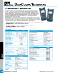
The full duplex/half duplex (F–H) manual switch has been provided for fiber port #1 in order to set the port at full or
half duplex as per the requirements. The F-H manual switch is located underneath the fiber port. The default setting
from the factory for the 100Mbps fiber port is full-duplex. The port can be changed by sliding the manual switch
position to “F” or “H”.
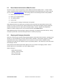
5.0
Status of LEDs
LED
STATUS
CONDITION
Power
ON - GREEN
Switch is receiving power.
Link / Act
ON - GREEN
Port has established a valid link.
BLINKING
Activity per port
ON – GREEN
100Mbps of speed per port
OFF
10Mbps of speed per port
ON – GREEN
Full duplex of connected port
OFF
Half duplex status of connected port
10/100
F/H
2
ProSwitch Converter Switch User’s Manual
Page 13
6.0
Troubleshooting
All Waters’ switching products are designed to provide reliability and consistently high performance in all network
environments. The installation of Waters’ ProSwitch CS series of converter switches is a straightforward procedure
(See Sections 3-5). Should problems develop during installation or operation, this section is intended to help locate,
identify and correct these types of problems. Please follow the suggestions listed below prior to contacting your
supplier. However, if you are unsure of the procedures described in this section or if the Waters’ ProSwitch converter
switch is not performing as expected, do not attempt to repair the unit; instead contact your supplier for assistance or
contact Waters Network Systems’ Customer Support Center at 800.328.2275 or email [email protected].
6.1
1.
2.
3.
4.
5.
6.
Before Calling for Assistance
If difficulty is encountered when installing or operating the unit, refer back to the Installation Section of the
chapter of this manual. Also check to make sure that the various components of the network are inter-operable.
Check the cables and connectors to ensure that they have been properly connected and the cables/wires have
not been crimped or in some way impaired during installation. (About 90% of network downtime can be attributed
to wiring and connector problems.)
Make sure that a DC power cord is properly attached to the ProSwitch converter switch.
Be certain that each AC power cord is plugged into a functioning electrical outlet. Use the PWR LEDs to verify
each unit is receiving power.
If the problem is isolated to a network device other than the Waters’ ProSwitch converter switch switch, it is
recommended that the problem device be replaced with a known good device. Verify whether or not the problem
is corrected. If not, go to next step. If the problem is corrected, the Waters’ ProSwitch converter switch and its
associated cables are functioning properly.
If the problem continues, contact Waters Network Systems Customer Service at 800.328.2275 or email
[email protected] for assistance.
When Calling for Assistance
Please be prepared to provide the following information.
1.
A complete description of the problem, including the following points:
a. The nature and duration of the problem
b. Situations when the problem occurs
c. The components involved in the problem
d. Any particular application that, when used, appears to create the problem
2.
An accurate list of Waters Network Systems product model(s) involved. Include the date(s) that you purchased
the products from your supplier.
3.
It is useful to include other network equipment models and related hardware, including personal computers,
workstations, terminals and printers; plus, the various network media types being used.
4.
A record of changes that have been made to your network configuration prior to the occurrence of the problem.
Any changes to system administration procedures should all be noted in this record.
2
ProSwitch Converter Switch User’s Manual
Page 14
6.2
Return Material Authorization (RMA) Procedure
All returns for repair must be accompanied by a Return Material Authorization (RMA) number. To obtain an RMA
number, call Waters Network Systems Customer Service at 800.328.2275 during business hours of 8:00 am to 5:00
pm (CT) or email [email protected]. When calling, please have the following information readily available:
Name and phone number of your contact person
Name of your company/institution
Your shipping address
Product name
Failure symptoms, including a full description of the problem
Waters Network Systems will carefully test and evaluate all returned products, will repair products that are under
warranty at no charge, and will return the warranty-repaired units to the sender with shipping charges prepaid (see
Warranty Information at the end of this manual for complete details). However, if Waters cannot duplicate the
problem or condition causing the return, the unit will be returned as: No Problem Found.
Waters Network Systems reserves the right to charge for the testing of non-defective units under warranty. Testing
and repair of product that is not under warranty will result in a customer (user) charge.
6.3
Shipping and Packaging Information
Should you need to ship the unit back to Waters Network Systems, please follow these instructions: Package the unit
carefully. It is recommended that you use the original container if available. Units should be wrapped in a "bubblewrap" plastic sheet or bag for shipping protection. (You may retain all connectors and this Installation Guide.)
CAUTION: Do not pack the unit in Styrofoam "popcorn" type packing material. This material may cause electro-static
shock damage to the unit.
Clearly mark the Return Material Authorization (RMA) number on the outside of the shipping container. Waters
Network Systems is not responsible for your return shipping charges.
Ship the package to:
Waters Network Systems
Attention: Customer Service
th
945 37 Avenue, NW
Rochester, MN 55901
2
ProSwitch Converter Switch User’s Manual
Page 15
7.0
Warranty
Waters Network Systems’
Warranty Statement
Waters Network Systems’ products are warranted against defects in materials and workmanship. The warranty
period for each product will be provided upon request at the time of purchase. Unless otherwise stated, the warranty
period is for the useable life of the product.
In the event of a malfunction or other indication of product failure attributable directly to faulty materials and/or
workmanship, Waters Network Systems will, at its option, repair or replace the defective products or components at
no additional charge as set for herein. This limited warranty does not include service to repair damage resulting from
accident, disaster, misuse, neglect, lightning, acts of God, tampering or product modification.
Service under the warranty may be obtained by contacting Waters Network Systems and receiving a Return Material
Authorization (RMA) number from Waters Network Systems. Returned product accompanied with the issued RMA
number and prepaid shipping will be repaired or replaced by Waters Network Systems. Repaired or replaced
products will be returned at no cost to the original Buyer and shipped via the carrier and method of delivery chosen by
Waters Network Systems.
Specific warranty by product family is as follows:
ProSwitch-Secure:
Limited Lifetime (see note)
ProSwitch-SecureAir+:
Limited Lifetime
ProSwitch-Lite:
3 Years from date of manufacture (see note)
ProSwitch-Xpress:
Limited Lifetime
ProSwitch-Xtreme:
Limited Lifetime (see note)
ProSwitch-FlexPort:
Limited Lifetime
ProSwitch-FixPort:
Limited Lifetime
ProSwitch-CS and CSX:
3 Years from date of manufacture (see note)
ProMedia Converters
3 Years from date of manufacture (see note)
Note: Warranty period for any and all external power supplies is one (1) year from date of purchase.
EXCEPT FOR THE EXPRESS WARRANTY SET FORTH ABOVE, WATERS NETWORK SYSTEMS GRANTS NO
OTHER WARRANTIES, EXPRESSED OR IMPLIED, BY STATUTE OR OTHERWISE, REGARDING THE
PRODUCTS, THEIR FITNESS FOR ANY PURPOSE, THEIR QUALITY, THEIR MERCHANTABILITY, OR
OTHERWISE.
WATERS NETWORK SYSTEMS’ LIABILITY UNDER THE WARRANTY SHALL BE LIMITED TO PRODUCT
REPAIR, OR REPLACEMENT OF THE BUYER’S PURCHASE PRICE. IN NO EVENT SHALL WATERS NETWORK
SYSTEMS BE LIABLE FOR THE COST OF PROCUREMENT OF SUBSTITUTE GOODS BY THE CUSTOMER OR
FOR ANY CONSEQENTIAL OR INCIDENTAL DAMAGES FOR BREACH OR WARRANTY.
2
ProSwitch Converter Switch User’s Manual
Page 16