1
Notice
The information in this guide is subject to change without notice.
Compaq Computer Corporation shall not be liable for technical or editorial
errors or omissions contained herein; nor for incidental or consequential
damages resulting from the furnishing, performance, or use of this
material.
This guide contains information protected by copyright. No part of this
guide may be photocopied or reproduced in any form without prior written
consent from Compaq Computer Corporation.
Copyright 1995, 1996 Compaq Computer Corporation.
All rights reserved. Printed in the U.S.A.
Compaq, Deskpro, LTE, Contura, Presario, ProLinea
Registered U. S. Patent and Trademark Office.
LTE 5000 is a trademark of Compaq Computer Corporation.
Contura Registered in the Philippines Patent Office.
Microsoft, MS-DOS, and Windows are registered trademarks of Microsoft
Corporation.
The software described in this guide is furnished under a license
agreement or nondisclosure agreement. The software may be used or copied
only in accordance with the terms of the agreement.
Product names mentioned herein may be trademarks and/or registered
trademarks of their respective companies.
MAINTENANCE AND SERVICE GUIDE
COMPAQ LTE 5000 FAMILY OF PERSONAL COMPUTERS
First Edition (September 1995)
Second Edition (November 1996)
Documentation Part Number 213583-002
Spare Part Number 213622-002
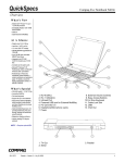
Chapter 1. Product Description
1.1 Computer Features and Models
The Compaq LTE 5000 Family of Personal Computers introduces a new
generation of performance notebook computers with advanced modularity,
Pentium processors with 64-bit architecture, PCI local bus graphics, and
extensive multimedia support. This full- function family of notebook
computers allows desktop functionality and connectivity via an optional
expansion base.
1.1.1 Computer Features
The Compaq LTE 5000 Family of Personal Computers has the following
standard features:
o Extensive multimedia support with integrated 16-bit digital stereo audio
(Microsoft Windows Sound System and SoundBlaster Pro compatible), dual
speakers, microphone, full motion video support, optional CD-ROM drive,
and optional MPEG and TV Video Adapter
o 75, 90, 100, 120, 133, or 150-MHz Intel Pentium processor with 64-bit
architecture
o 8 or 16 MB of RAM, expandable to 72 or 80 MB
o 512 KB of 64-bit write-back, synchronous, level-2 cache memory available
on the LTE5400 model; 256 KB of 64-bit write-back, synchronous,
level-2 cache memory available on all other models
o Upgradable flash ROM BIOS
o High-performance 32-bit PCI local bus graphics with hardware-assisted
Motion Video Acceleration (MVA)
o Color TFT VGA or SVGA, CSTN VGA or SVGA, or CTFT 1024 x 768 display
panels
o Keyboard with built-in EasyPoint II pointing device and mouse buttons
o Removable hard drive
o MultiBay modular device bay that supports a CD-ROM drive, a second hard
drive, a second battery pack, or diskette drive, and a full-length ISA
slot that allows addition of an ISA expansion board (ISA slot available
with MultiBay ISA Expansion Base only)
o Two Type III PC Card (PCMCIA) slot that supports one Type III, two Type
I, or two Type II PC Cards, LAN connection or data/fax modem
o Infrared port for IrDA wireless data transfer, printing, and drive
synchronization
o Ports and connectors for external equipment (see Section 1.3)
o Preinstalled software
o Security features
o Desktop functionality available with the optional Compaq LTE 5000
MultiBay Expansion Base or MultiBay ISA Expansion Base.
1.1.2 Computer Models
The Compaq LTE 5000 Family of Personal Computers is available in the
models shown in Table 1-1.
Table 1-1. Compaq LTE 5000 Family of Personal Computers Models
===========================================================================
Model
Processor
Display
Hard Drive
CD-ROM Drive
===========================================================================
LTE 5000 Model
Pentium/75
10.4-inch
510 MB
Optional
510 CSTN
CSTN/VGA
--------------------------------------------------------------------------LTE 5000 Model
Pentium/75
11.3-Inch
810 MB
Optional
810 CSTN
CSTN/SVGA
--------------------------------------------------------------------------LTE 5000 Model
Pentium/75
10.4-Inch
810 MB
Optional
810 CTFT
CTFT/VGA
--------------------------------------------------------------------------LTE 5100 Model
Pentium/90
10.4-Inch
810 MB
Optional
810 CTFT
CTFT/SVGA
--------------------------------------------------------------------------LTE 5100 Model
Pentium/90
10.4-Inch
810 MB
Yes
810 CD CTFT
CTFT/SVGA
--------------------------------------------------------------------------LTE 5150 Model
Pentium/100
11.3-inch
810 MB
Yes
810 CSTN 800
CTFT/SVGA
x 600
--------------------------------------------------------------------------LTE 5200 Model
Pentium/120
10.4-inch
1.35 GB
Optional
1350 CTFT
CTFT/SVGA
--------------------------------------------------------------------------LTE 5250 Model
Pentium/120
10.4-inch
810 MB
Yes
810 CTFT
CTFT/SVGA
800 x 600
--------------------------------------------------------------------------LTE 5280 Model
Pentium/120
11.3-inch
810 MB
Yes
810 CTFT
CTFT/SVGA
800 x 600
--------------------------------------------------------------------------LTE 5280 Model
Pentium/120
11.3-inch
1.35 GB
Yes
1350 CTFT
CTFT/SVGA
800 x 600
--------------------------------------------------------------------------LTE 5300 Model
Pentium/133
12.1-inch
1.35 GB
Yes
1350 CTFT
CTFT/SVGA
800 x 600
--------------------------------------------------------------------------LTE 5300 Model
Pentium/133
12.1-inch
2.16 GB
Yes
2160 CTFT
CTFT/SVGA
800 x 600
--------------------------------------------------------------------------LTE 5380 Model
Pentium/133
12.1-inch
2.16 GB
Yes
2160 CTFT
CTFT/10 X 7
1024 x 768
--------------------------------------------------------------------------LTE 5400 Model
Pentium/150
12.1-inch
2.16 GB
Yes
2160 CTFT
CTFT SVGA
800 x 600
===========================================================================
1.1.3 Preinstalled Software
The computer can have either Windows 3.1 or Windows 95 installed.
Windows 3.1 Software Components
The following software is preloaded if Windows 3.1 is installed:
o MS-DOS 6
o Microsoft Windows 3.1
o Cirrus GD-754x Video Driver
o TEAC CD-40E CD-ROM Driver and CD Audio Player for DOS
o ESS Audio Driver and Audio Clip Library
o Compaq Sound System Version 1.70
o Compaq Network Interface Drivers
o Compaq PCMCIA 3.14
o Logitech Mouse Ware 6.46
o PUMA TranXit Version 1.03
o Microsoft Video for Windows 1.10e (Runtime version)
o Machine Check Version 1.1 (MACHCHK.SYS)
o SystemSoft Suspend-To-Disk Utility 2.20.00 (0VMAKFIL.EXE)
o Compaq Supplementary Programs
o Microsoft Supplementary Programs
o SAFETY & COMFORT GUIDE
o COMPAQ DICTIONARY
o COMPAQ USER'S GUIDE
o ONLINE OPTIONS CATALOG
o Compaq Diagnostics for Windows 1.05
o CompuServe WinCIM (1.4/1.2/1.31D/1.31F)
o America Online for Windows (North America only)
Windows 95 Software Components
The following software is preloaded if Windows 95 is installed:
o Cirrus Logic GD-754x Video Driver
o TEAC CD-40E CD-ROM Driver
o Compaq PCMCIA 3.14 Installer for Windows 95
o Logitech Mouse Ware 6.50
o Machine Check Version 1.1 (MACHCHK.SYS)
o SystemSoft Suspend-To-Disk Utility 2.20.00 (0VMAKFIL.EXE)
o Microsoft Infrared Monitor and Direct Cable Connect
o SAFETY & COMFORT GUIDE
o COMPAQ DICTIONARY
o COMPAQ ONLINE USER'S GUIDE
o ONLINE OPTIONS CATALOG
1.1.4 Intelligent Manageability
Intelligent Manageability combines innovative hardware technology with PC
LAN management tools from Compaq and other leading vendors to make Compaq
portable computers easier to inventory, troubleshoot, and protect.
Asset Management
AssetControl is asset management software designed to cut the time and
cost of conducting a physical inventory of personal computers, key
components, and monitors. AssetControl is preinstalled on portable
computers, key components, and monitors that support the Video Electronics
Standards Association Data Display Channel (VESA DDC) and Extended Display
Identification Data (EDID) standards.
AssetControl features make it easy and inexpensive to maintain an
accurate, up-to-date inventory. Detailed inventory information, including
manufacturer, model, serial number, asset tag, and ROM revision level can
be viewed, printed, or saved electronically using Compaq Insight Personal
Edition or Compaq Insight Manager.
Compaq Insight Personal Edition refers to Intelligent Manageability
software that diagnoses portable computer hardware, monitors the internal
system temperature and IntelliSafe hard drive, and then displays a
prefailure warning message on detecting a system temperature or hard drive
fault.
Compaq Insight Manager refers to Information Manageability software that
helps manage servers and personal computers on a network. Compaq Insight
Manager features intelligent monitoring and alerting, remote maintenance,
and visual control of network resources.
Fault Management
Fault Management is a utility designed to help prevent the loss of
critical data. This feature is available only in the 2.16GB DFP (SMART
system compliant drives). Fault Management has the following features:
o SMART (IntelliSafe) hard drive - Constantly monitors hard drive activity
to predict failures before they occur.
o Temperature sensing - Hardware and software that tracks the internal
temperature of the computer and displays a warning message when the
normal range is exceeded.
Compaq Insight Personal Edition displays a pop-up message to notify you
when a hard drive or system temperature fault is detected. If the computer
is connected to a network managed by Compaq Insight Manager, fault notices
are also sent to the network management application.
Security Management
The security management utility provides a set of security features to
protect the computer and data from unauthorized access.
o Passwords - Prevents unauthorized access to information stored on the
computer or network.
o Drive security - Prevents starting the computer from the diskette drive
and reading information from the diskette drive.
o Device disabling - Prevents unauthorized data transfer over fax/modems,
serial ports, parallel ports, and infrared ports.
1.1.5 Security Features
The computer has the following security features:
o Ability to secure drives in the dedicated hard drive bay and computer
MultiBay
o Ability to secure the computer and either MultiBay Expansion Base to an
immovable object with an optional cable lock
o Ability to establish power-on and setup passwords and to disable ports
and devices from the Security menu in Computer Setup
1.1.6 Power Management
Power Management offers three levels of power conservation:
o High: Provides the maximum amount of power conservation and the maximum
battery operating time from a single charge.
o Medium: Provides a balance between performance and battery life (factory
default).
o Custom: Conserves power according to user-specified timeout settings.
The conservation level sets the timeouts for Standby (Suspend),
Hibernation, drives, and screens. Use the Fn+F7 hotkeys to toggle off and
on the power management settings in Computer Setup and Windows Power
Properties.
Selecting to disable the infrared port under the Security menu also
conserves power.
Chapter 1.2 Computer Options
The options that are available from Compaq for the computer are described
in the following sections.
1.2.1 MultiBay Expansion Base and MultiBay ISA Expansion Base
The MultiBay Expansion Base and the MultiBay ISA Expansion Base provide
two additional MultiBay device bays, two PC Card Type III slots,
integrated Ethernet, integrated stereo speakers, and computer I/O port
replication. The expansion bases are described in Section 1.5. When the
computer is docked in an expansion base, the total system functionality
includes:
o Support for up to three MultiBay devices simultaneously
o Overall system support for up to four hard drives or two diskette drives
o Up to three CD-ROM drives installed as follows:
- Three CD-ROM drives: The two in the expansion base must be used for
data; the CD-ROM drive in the computer can then be used for audio or data.
- Two CD-ROM drives: You can have one in the expansion base and one in
the computer; either drive can be data or audio. If both drives are in
the expansion base, they must be for data only.
- One CD-ROM drive: It can be either data or audio and in either the
computer or expansion base.
o Two Type III PC Card slots
o Overall system support for up to four PC cards
o Charging of up to four battery packs
The MultiBay ISA Expansion Base provides the same functionality as the
MultiBay Expansion Base, with the following additional features:
o One ISA Expansion slot allows ability to add a full-length ISA expansion
board
o Additional ventilation exhausts on both sides of the expansion base for
increased ventilation
o High performance stereo speakers and new audio bass ports on both sides
of the expansion base for "PremierSound" CD-quality audio
1.2.2 System Memory Options
The main memory subsystem supports a minimum standard 8 MB or 16 MB of
DRAM, expandable to a maximum of 72 or 80 MB. The minimum standard DRAM is
integrated on the processor board. The upgrade DRAM is accomplished with
memory expansion boards that are available in 8, 16, 32, and 64 MB
increments. The memory expansion boards require no special tools for
installation and can be installed by the inexperienced user. System memory
can be upgraded according to the schedule in Table 1-2:
Table 1-2. Memory Upgrade Schedule
===========================================================================
Base Memory
Memory Expansion Board
Total Memory
===========================================================================
8/16 MB
None
8/16 MB
8/16 MB
8 MB
16/24 MB
8/16 MB
16 MB
24/32 MB
8/16 MB
32 MB
40/48 MB
8/16 MB
64 MB
72/80 MB
===========================================================================
1.2.3 Mass Storage Options
The following mass storage options are available for the computer:
o 3.5-inch 1.44 MB Diskette Drive
o 510 MB IDE Hard Drive
o 810 MB IDE Hard Drive
o 1.35 GB IDE Hard Drive
o 2.16 GB w/DFP IDE Hard Drive
o 2.16 GB IDE Hard Drive
Diskette Drive
The computer uses a 3.5-inch diskette drive that is enclosed in a module
that fits into the MultiBays of the computer or the MultiBay Expansion
Base and the MultiBay ISA Expansion Base. The diskette drive is a
three-mode type that is compatible with 1.44 MB, 1.2 MB and 720K AT drive
types. The system supports a maximum of two diskette drives: one in the
computer, one in the MultiBay Expansion Base. When using Windows 95, real
mode drivers must be used for a diskette drive in the expansion base. For
more information see "Solving Diskette and Diskette Drive Problems" in
Chapter 2.
Hard Drive
The computer supports an IDE hard drive in the dedicated hard drive bay.
Cable select technology is employed for device 0/device 1 (master/slave)
selection. The hard drive can be locked in place with the hard drive
security screw installed adjacent to the hard drive release on the bottom
of the computer. See Appendix C for information on using Compaq LTE Elite
hard dives in the computer.
1.2.4 CD-ROM Drive
The modular, 2x, 4x, and 6x CD-ROM drives are available from Compaq as a
standard model or an option for the computer or either expansion base. The
CD-ROM drive is compatible with industry-standard CD-ROM disc media and
formats. It can read:
o CD-Digital Audio
o CD-ROM Mode 1 and Mode 2
o CD-ROM/XA Mode 2 (Form 1 and Form 2)
o CD-I Mode 2 (Form 1 and Form 2)
o Video CD
o Photo CD (single and multisession)
o ISO 9660 and High Sierra
1.2.5 MPEG and TV Video Adapter
The MPEG and TV Video Adapter option is supported with the computer and
both expansion bases. This option provides an MPEG decoder for high
quality digital video playback with Windows scaling and interleaved stereo
audio, S-Video I/O for laser disc quality playback video, and composite
video supporting the NTSC/PAL formats.
1.2.6 Miscellaneous Options
The following options for the computer are also available from Compaq:
o AC Adapter
o Automobile Adapter
o NiMH Battery Pack
o Battery Fastcharger
o Enhanced III External Keyboard
o Compaq Mouse
o Carrying Case
o MultiBay Device Carrying Case
o MultiBay Hard Drive Adapter
AC Adapter
The AC Adapter supplies DC voltage to the system DC-to-DC converter for
use by the system to operate and/or charge the installed battery pack(s).
The adapter provides sufficient power to charge each main battery pack in
1.5 hours or less with the system off. The adapter also powers the Battery
Fastcharger.
Automobile Adapter
The Automobile Adapter is used to charge the computer from an automobile
battery. It also powers the Battery Fastcharger.
External Battery Fastcharger
The external Battery Fastcharger is available from Compaq and has the
following features:
o Two battery charge bays
o Fast charging of one battery in 1.5 hours
o Fast charging of two batteries in 3 hours
It requires the AC Adapter or Automobile Adapter for power.
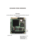
Chapter 1.3 Computer External Components
The external components on the front and right sides of the computer are
shown in Figure 1-2 and are described in Table 1-3.
Table 1-3. Computer Components - Front and Right Sides
===========================================================================
Item
Component
Function
===========================================================================
1
Power switch
Turns the power on and off.
--------------------------------------------------------------------------2
Display switch
Turns display off and initiates beep if
display is closed with computer on. When
used with the standby button, restarts the
computer.
--------------------------------------------------------------------------3
Standby switch
Initiates/exits Standby. When used with
the display switch, restarts the
computer. When used with the Fn key,
initiates Hibernation.
--------------------------------------------------------------------------4
Status panel icons
The computer is connected to an external
power source.
QuickLock/QuickBlank has been initiated.
Type the power-on password on the
blank screen to exit
QuickLock/QuickBlank.
Power Management is turned on. Run
Computer Setup to view or change
Power Management settings.
A diskette drive in the MultiBay is
being accessed.
A hard drive in the dedicated hard
drive bay or a hard drive or CD-ROM
drive in the MultiBay is being accessed.
An external monitor is actively
displaying information.
The built-in speakers on the front of the
display or speakers or headphone
connected to the computer or expansion
base are turned on.
Num lock is on, which enables the
embedded numeric keypad.
Caps Lock is on, which causes new text
to be typed in uppercase letters.
Scroll Lock is on, which causes the
cursor to scroll by fields, rather than
by lines.
Battery gauges 1 and 2. Gauge 1 turns on
if a battery pack is in the dedicated
battery bay and shows the amount of
charge in the battery pack. Gauge 2 turns
on if a battery pack is in the MultiBay
and shows the amount of charge in that
battery pack.
--------------------------------------------------------------------------5
Ventilation intake
Intake vents provide proper airflow to
help prevent the computer from
overheating.
--------------------------------------------------------------------------6
Stereo speakers
Built-in stereo speakers for PC and
multimedia sound system.
--------------------------------------------------------------------------7
Latch
Secures computer in a closed position;
release to open.
--------------------------------------------------------------------------8
Brightness control
Adjusts the brightness of the display.
Contrast control (not
Adjusts the contrast of the display
shown)
(CSTN models).
--------------------------------------------------------------------------9
Standby (suspend) light
Illuminates when power to the computer
(green)
is turned on. Blinks to indicate
computer is in Standby (Suspend).
--------------------------------------------------------------------------10
Battery light (yellow)
Illuminates when a battery pack is
charging; turns off when the battery
pack is fully charged; blinks to
indicate low battery.
--------------------------------------------------------------------------11
Microphone
Built-in microphone for the Compaq
Sound System.
--------------------------------------------------------------------------12
PC Card slots
Accepts one Type III or two Type II or
two Type I PC Cards (PCMCIA).
--------------------------------------------------------------------------13
Battery release
Releases a battery pack in the battery
compartment.
--------------------------------------------------------------------------14
Keyboard
Keyboard with EasyPoint II pointing
device and pick buttons.
--------------------------------------------------------------------------15
Battery compartment
Dedicated battery compartment for the
main battery pack.
--------------------------------------------------------------------------16
Hard drive bay
Dedicated hard drive bay.
--------------------------------------------------------------------------17
MultiBay
Bay that supports multiple devices:
CD-ROM drive, hard drive, battery pack,
or diskette drive.
===========================================================================
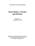
The external components on the rear and left sides of the computer are
shown in Figure 1-3 and described in Table 1-4.
Table 1-4. Computer Components - Rear and Left Sides
===========================================================================
Item
Component
Function
===========================================================================
1
Serial number
Identifies the computer.
--------------------------------------------------------------------------2
Serial connector
Connects optional serial devices.
--------------------------------------------------------------------------3
Parallel connector
Connects optional parallel devices.
--------------------------------------------------------------------------4
External options
Connects the expansion base or the
connector
optional Automobile Adapter.
--------------------------------------------------------------------------5
External monitor connector
Connects an external monitor.
--------------------------------------------------------------------------6
Power connector
Connects the AC Adapter or the
optional Automobile Adapter.
--------------------------------------------------------------------------7
Stereo speaker/headphone
Connects external speakers or
jack
headphones.
--------------------------------------------------------------------------8
Stereo line in jack
Stereo line-in jack for CD player,
tape deck, tuner, or other line level
audio source.
--------------------------------------------------------------------------9
Keyboard/mouse connector
Connects an external keyboard, numeric
keypad, PS/2 mouse, or other pointing device.
--------------------------------------------------------------------------10
Docking sensor
Access to a microswitch that initiates
the docking scenario when the computer
is being docked. Also serves as a
guide for the MPEG Adapter.
--------------------------------------------------------------------------11
Mono microphone jack
Connects a powered electric condenser
microphone.
--------------------------------------------------------------------------12
Volume control
Controls volume to the built-in
speakers or to external speakers or
headphones connected to the computer
or MultiBay Expansion Base.
--------------------------------------------------------------------------13
MultiBay device release
Releases a drive or battery pack from
the MultiBay.
--------------------------------------------------------------------------14
Ventilation exhaust
Exhaust vent for proper airflow to
help prevent the computer from
overheating.
--------------------------------------------------------------------------15
Infrared port
Transfers data to another computer or
external device that accepts IrDA
format.
--------------------------------------------------------------------------16
Security slot
Provision for an optional security
cable lock to be attached to the
computer.
===========================================================================
Chapter 1.4 Design Overview - Computer
This section presents a design overview of the computer. The discussion is
limited to the field replaceable parts. All replaceable parts are
identified in Chapter 3, and removal/replacement procedures are presented
in Chapter 5.
The computer is a traditional clamshell design with a display unit and
system unit. The computer opens to reveal a backlighted LCD display and
keyboard. The display is designed for a continuously adjustable tilt
angle. The system unit houses the system board, processor board, power
board, keyboard, I/O ports, operator controls and indicators, mass storage
device bays, and battery bay.
The main components of the system unit include the following:
o Processor (Intel Mobile Pentium 75 MHz, 90MHz, 100MHz, 120MHz, 133mhz,
or 150 MHz)
o System controller (OPTi 556/557/558N, OPTi 602A)
o VGA controller (Cirrus CL-GD754x)
o Keyboard controller (Intel 80C51SL)
o PCMCIA controller (Cirrus 6722)
o Super I/O (National 87334)
o Audio controller (ESS688 or ESS1688)
o Power controller (47P440AF)
The boards on which these controllers reside are identified in the
sections that follow.
1.4.1 Display Unit
The display unit includes the following field replaceable components:
o Display assembly
o Display bezel with speakers
o Release latches
o Brightness control actuator
o Contrast control actuator (CSTN models only)
o Clutch assemblies
o Compaq logo
Display Assembly
The display assembly is replaced as a complete unit that includes:
o LCD panel
o LCD inverter
o Display bezel
o Stereo speakers
o Clutch assemblies
o Release latches
o Brightness control actuator
o Contrast control actuator (CSTN models only)
NOTE: The display bezel, release latches, brightness/contrast control
actuator(s), Compaq logo, and clutch assemblies can also be replaced
individually. The speakers are permanently installed on the display
bezel.
The following LCD panels are supported:
o 10.4-inch (26.4 cm) CSTN VGA Display (640 x 480)
o 11.3-inch (28.7 cm) CSTN SVGA Display (800 x 600)
o 10.4-inch (26.4 cm) CTFT VGA Display (640 x 480)
o 10.4-inch (26.4 cm) CTFT VGA Display (800 x 600)
o 11.3-inch (28.7 cm) CTFT SVGA Display (800 x 600)
o 12.1-inch (30.7 cm) CTFT SVGA (800 x 600)
o 12.1-inch (30.7 cm) CTFT 1024 x 768 Display
Both LCD panels have a controllable backlight intensity that can be
adjusted with a slide switch. The CSTN (dual scan) panels also have a
slide switch for contrast control.
The LCD panel inverter cable plugs into an 8-pin connector on the
processor board. The LCD cable plugs into a connector on the system board.
The inverters and cables differ according to the display type and
manufacturer and cannot be interchanged. All of the display cables are
routed to the system unit in the vicinity of the clutches.
NOTE: It is important that these instructions be followed when replacement
of any part requires removal of the display assembly.
Slide the display assembly back in place and replace all screws. The
screws must be fully tightened to ensure that they do not touch the
expansion base sensor located near the left hinge. Failure to properly
seat the screws may prevent the unit from booting up.
NOTE: Use Fn+F4 hotkeys to switch between external, internal, and
simultaneous display. (The CSTN 800 x 600 does not support
simultaneous display.)
Display Bezel With Speakers
The display bezel attaches to the display unit with a snap action and is
secured with a screw at each corner. Screw covers are installed over the
screw heads. After removing these screws, use a Compaq bezel removal tool
to separate the bezel from the display assembly. The display bezel can be
removed without separating the display unit from the system unit.
The internal stereo speakers are 0.5-watt, 8-ohm, permanently installed in
the top corners of the display bezel and are installed as a unit with
cabling attached. The speaker cable is routed into the system unit and
connects to a 4-pin connector adjacent to the 30-pin LCD connector on the
system board. The CPU cover is easily removed from the system unit to
access this connector.
NOTE: Use Fn+F5 hotkeys to toggle speakers/headphones off and on.
Release Latches
The release latches serve to lock the display and system units together
when the computer is in the closed position. Each latch assembly consists
of three parts:
o Latch actuator
o Latch hook
o Latch spring
The release latch assembly is available as a field replaceable unit. The
display bezel must be removed to replace the latch assemblies.
The release latches are mounted in the display unit back cover. The
display bezel must be removed to access the latches. The latches snap into
place and require a simple depression of a tab to be released from the
display cover.
Brightness/Contrast Control Actuator(s)
The displays have a controllable backlight intensity that can be adjusted
with a slide switch. The CSTN panels also have slide switch for contrast
control. The actuators for these adjustments are available as field
replaceable units.
The brightness/contrast control actuator(s) (contrast control actuator on
CSTN displays only) are mounted on the display bezel with a snap action.
The display bezel must be removed to allow the tabs on the back side of
the actuator to be depressed for removal. When installing a display bezel,
make certain the brightness/contrast actuator(s) aligns with the
brightness/contrast control(s) in the display assembly.
Clutch Assemblies
The clutch assemblies provide the hinge function between the display unit
and system unit and also provide continuous tension that allows the
display unit to be positioned at any angle.
The clutch assemblies are available in pairs as field replaceable units.
Each clutch assembly is mounted to the display unit with two screws and to
the system unit with two screws. Removal and replacement of the clutch
assemblies requires removal of the display bezel and the CPU cover (on the
system unit).
Compaq Logo
The Compaq logo is installed on the back of the display unit. The location
for the logo is indicated by an ellipse embossed in the cover. The logo is
an adhesive-backed label that is available as a field replaceable unit.
The label indicates which processor is installed in the computer.
1.4.2 System Unit
The system unit contains the following field replaceable units:
o CPU cover
o Internal microphone
o Status panel
o Processor board
o Power board
o Cooling fan
o System board
o Memory expansion board (optional)
o Keyboard assembly
o Auxiliary battery
o Miscellaneous plastic parts
CPU Cover
The CPU cover is located above the keyboard and is secured in place with
three screws on the rear panel of the system unit. Tabs on the front edge
of the CPU cover engage slots across the top edge of the keyboard panel.
The CPU cover contains the actuators for the following:
o Power switch
o Standby (Suspend) button
o Display switch
The CPU cover with all switch actuators installed is available as a field
replaceable unit. The switch actuators are also available as field
replaceable units.
The power switch actuator and spring and the standby (suspend) button
actuator and spring are removed by squeezing the actuator tabs on the
underside of the CPU cover and pushing the buttons out of their mounting
hole. The display switch actuator simply snaps out of its mounting hole
from the underside of the CPU cover.
The CPU cover must be removed to service any of the above described switch
actuators. The cover also must be removed to disconnect any of the display
unit cables from the system unit, to remove the display unit, to service
the status panel, and to remove the keyboard assembly.
Internal Microphone
The internal microphone is supported by the audio subsystem and connects
to the system board. It is an omnidirectional condenser microphone with a
standard sensitivity of 40dB. The microphone is mounted in a rubber boot
to provide acoustic isolation and is mounted at the right side of the
keyboard, under the CPU cover.
Status Panel
The status panel is located immediately below the LCD panel on the system
unit. The panel displays a series of icons to indicate system status as
described in Table 1-3.
The status panel also contains two status indicator lights. The right
indicator light provides battery status; the left indicator light provides
power-on and Standby (Suspend) status. Access to the display panel for
service requires removal of the CPU cover. The status display is secured
with two screws. The status panel cable plugs into an 8-pin connector on
the processor board.
Processor Board
The processor board supports the following:
o Processor
o DC-to-DC converter is used only with processors that operate at higher
than 75 MHz.
o L2 cache
o System RAM
o System memory expansion connector
o Power, display, and standby switches
o Infrared serial port (IrDA)
o Display panel configuration jumpers
o Power-on password jumper
The computer supports 75, 90, 100, 120, 133-, and 150-MHz Mobile Pentium
processors. The processor is soldered to the processor board, so
replacement is accomplished by replacing the processor board. A heat sink
on the processor and a cooling fan maintain an operating temperature
within the limits specified by the CPU manufacturer and other components.
All I/O buffers operate at 3.3 volts.The 75-MHz processor core operates at
3.3 volts. The 150-MHz processor core operates at 3.1 volts. The 90-Mhz,
100mhz, 120-MHz, and 133-MHz processor cores operate at 2.9 volts. The 2.9
volts is provided by a DC-to-DC converter mounted on the processor board.
The processors are of a tape carrier package (TCP) design that has a high
pin count, low profile, and reduced footprint. The processor is easily
damaged, so the pins and body of the processor should not be touched.
The L2 cache is implemented as direct-mapped, write-back cache with a size
of 256 KB.
The power switch, display switch, and standby (suspend) button are mounted
on the processor board. They are operated by switch actuators mounted on
the CPU cover.
The power switch turns system power on and off. When the switch is pushed
to turn the power off, the system displays a warning message that all
unsaved data will be lost. The shut down process is then completed by
pressing Enter.
The display switch turns the display off and initiates a beep if the
display is closed with the computer on. When used with the standby switch,
the display switch initiates a system restart.
The standby (suspend) button initiates and exits Standby (suspend). As
described above, the standby button, when used with the display switch,
initiates a system restart. When used with the Fn key, the standby button
initiates Hibernation.
The processor board contains 8 MB or 16 MB of onboard memory and can be
expanded to 72 or 80 MB by adding a 64 MB memory expansion board. The
memory expansion boards are available in 8, 16, 32, and 64 MB DRAM
configurations. Each module is composed of two boards assembled together.
The system ROM is shadowed in system memory.
The infrared subsystem (IrDA) provides two-way wireless communication
using infrared as a transmission medium. Proper operation requires the
communicating infrared ports to be within a 30-degree path and no more
than three feet (1 meter) apart.
The processor board must be configured according to the display type. This
is done by setting Jumpers JP2, JP3, and JP4 on the processor board. Use
Table 1-5 to determine proper jumper settings for the display.
Table 1-5. Display Configuration Jumpers
===========================================================================
Display Type
Jumper JP3
Jumper JP2
Jumper JP4
===========================================================================
LTE 5000 10.4 in VGA CSTN
1-2
2-3
1-2
LTE 5000 10.4 in VGA CTFT
2-3
2-3
1-2
LTE 5000 11.3 in SVGA CSTN
1-2
2-3
2-3
LTE 5100 10.4 in SVGA CTFT
2-3
2-3
2-3
LTE 5200 10.4 in SVGA CTFT
2-3
2-3
2-3
LTE 5280 11.3 in SVGA CTFT
2-3
2-3
2-3
LTE 5300 12.1 in SVGA CTFT
2-3
2-3
2-3
LTE 5150 Rev. 4X 11.3 in
SVGA CSTN
1-2
1-2
1-2
LTE 5150 Rev. 2X SVGA CSTN
2-3
1-2
1-2
LTE 5250 10.4 in SVGA CTFT
2-3
2-3
2-3
LTE 5380 12.1 in 1024 x 768
CTFT
2-3
1-2
1-2
LTE 5400 12.1 in 1024 x 768
CTFT
2-3
2-3
2-3
===========================================================================
The power-on password jumper is also located on the processor board. To
erase the power-on password, set jumper JP1 to pins 1 and 2; set JP1 to
pins 2 and 3 for normal operation. See Chapter 2 for more details.
To remove and replace the processor board, you must first remove the CPU
cover, EMI shield, keyboard, and display unit. The processor board is
secured in place with two screws and is connected to the system board with
two connectors.
System Board
There are three system boards for the computer: one to support the 75 MHz,
90 MHz and 120 MHz processors (LTE 5000, LTE 5100, and LTE 5200); one to
support the 120 MHz, 100MHz, and 133 MHz processors (LTE 5280, LTE 5300,
LTE 5150, and LTE 5250); and one to support the 133 MHz processor (LTE
5380) and 150MHz processor (LTE 5400). The system board supports the
following:
o System ROM (BIOS)
o Graphics subsystem
o Audio subsystem
o PC Card subsystem
o Diskette drive controller
o RS-232 and IrDA serial ports
o IDE interface
o Fan connector
o I/O connectors
The firmware components for the computer include:
o System BIOS for the OPTi Viper Notebook chip set
o ROM-based setup
o MAXIMIZER Power Management for OPTi Viper
o APM 1.1 BIOS
o Plug and Play BIOS
o PCI BIOS
o Keyboard Controller Firmware for the Intel 80C51SL
o VGA BIOS
The ROM-based setup has been translated into ten languages in addition to
English. Messages that are displayed by the BIOS which require no user
interaction are displayed in English. This includes POST warning messages,
error messages, and runtime warnings and notifications. Messages that are
displayed by the BIOS which require user interaction are translated into
the same language as Setup.
The graphics controller interfaces with the system through the PCI bus.
The controller provides backward compatible modes to support CGA, EGA,
MGA, and HGA as well as all current VGA and SVGA modes. The controller
supports the internal LCD panels as well as an external CRT and
simultaneously supports the LCD and CRT (except for models with the
11.3-in CSTN SVGA display). The CRT interface is also routed to the either
expansion base through the external options connector. For LCD only and
LCD/CRT simultaneous display modes, the following panel and color
resolutions are supported:
Table 1-6. Maximum Resolutions Supported
===========================================================================
Display Type
Display Modes
Color Depth Supported
===========================================================================
640 x 480 CTFT
640 x 480
256, 64K, 16M
800 x 600 CTFT
640 x 480, 800 x 600
256, 64K
640 x 480 CSTN
640 x 480
256, 64K
800 x 600 CSTN
640 x 480, 800 x 600
256
1024 x 768 CTFT
1024 x 768
256
===========================================================================
The graphics controller also supports display of real-time video from the
MPEG and TV Video Adapter at a rate of 30 frames per second (fps). It
provides the capability to overlay the video in a Windows screen.
The computer has 1 MB of video DRAM soldered to the system board.
is no provision for adding additional video memory.
There
The graphics subsystem is designed to minimize the use of power at all
times. When the system is idle for a set period of time, the controller is
placed in the lowest power state. The LCD panel backlight and panel power
are turned off during periods of inactivity after a timeout as determined
by the user in Computer Setup. The system supports Energy Star monitors
and allows the feature to be turned on/off from Computer Setup.
The computer supports an interface to an MPEG and TV Video Adapter that
attaches to the rear of the computer. The adapter provides up to 30 fps of
live video or MPEG video to the graphics controller for display on the
LCD, a CRT, or a television. The MPEG and TV Video Adapter and CD-ROM
drive can be used simultaneously.
The audio subsystem is integrated into the system board. The system
supports an internal microphone, stereo speakers, SoundBlaster PRO
compatible audio, CD-ROM audio inputs, an external jack for headphones or
speakers, microphone jack, and line-input jack. Line and CD-ROM inputs and
the speaker outputs are passed through the external options connector and
supported by both expansion bases.
The internal speakers are disabled when the computer is docked in the
expansion base and when headphones or external speakers are installed.
The heart of the audio subsystem is the ESS1688 (ESS688 on Windows 3.1/Dos
6 units) AudioDrive ASIC that provides 16-bit stereo WAV audio, audio
mixing, and FM music synthesis. The entire audio system connects directly
to the ISA bus.
The ESS1688 is OPL3 compatible and compatible with SoundBlaster PRO and
Microsoft Windows Sound System. It can record, compress, and play back
sound and music at 8 or 16 bits up to 44 Khz.
The computer has one PC Card (PCMCIA) controller that supports a Type III
PC card slot that supports either two Type II PC Cards or one Type III PC
Card. A PC card door prevents contamination of the slot. The controller is
Intel ExCA compatible and complies with the Berlin revision of the PCMCIA
standard. The controller supports 5-V cards and all current Compaq PC
Cards. A second PC Card controller is located in both expansion bases.
The diskette drive controller supports 720K, 1.2 MB, and 1.44 MB densities
as well as automatic media detection. Diskette drives can be used in the
computer MultiBay and the expansion bases. When using Windows 95, real
mode drivers must be used for a diskette drive in the expansion base. For
more information see "Solving Diskette and Diskette Drive Problems" in
Chapter 2.
The PC87334 Super I/O contains two UARTs which are fully compatible with
NS15450 and NS16550. Both ports support MIDI baud rates and one port also
supports IrDA and HP SIR compliant signaling protocol. The two serial
ports are configured as one RS- 232C serial port and one infrared (IrDA)
port.
o The standard RS-232 serial port has an 82550 compatible serial
controller. The physical connector is a standard 9-pin D connector. The
interface can be configured as COM1, COM2, COM3, or COM4.
o The infrared communication is implemented with an 82550 compatible
serial controller. The minimum data rate supported by the Infrared Port
is 115K bits per seconds. The interface can be configured as COM1, COM2,
COM3, or COM4.
The parallel port support is integrated into the PC87334 Super I/O. The
computer has one parallel port that can be configured to operate in
compatible mode, enhanced modes 1.7 and 1.9 (EPP), and extended
capabilities (ECP) mode (IEEE-1284 compatible). The default mode is the
compatible mode. The physical connector is a standard 25-pin D connector.
The parallel port interface can be configured as LPT1, LPT2, or LPT3.
When the computer is mounted in either expansion base, the system can
support up to four IDE hard drives. When using two hard drives in the
computer, one of the hard drives is installed in the dedicated hard drive
bay and the other in the MultiBay.
NOTE: The dedicated hard drive bay provides limited support for the Compaq
LTE Elite hard drive. See Appendix C for details.
The hard drive remains powered off from Standby (Suspend) until the first
access occurs. The hard drive is powered off during Standby (Suspend).
The cooling fan is mounted in the system unit on the left side at the
ventilation exhaust port. Functioning as an exhaust fan, it provides air
flow across the electronic components for cooling. The fan plugs into a
2-pin connector on the system board.
The I/O connector panel is an integral part of the system board. In
addition to the I/O panel, the system board supports the following:
o PC card rails and connectors
o Battery bay contacts
o Hard drive bay connector
o MultiBay mass storage device connector
o MultiBay battery contacts
o Power board connectors
o Processor board connectors
o Fan connector
o LCD panel connector
o Speaker connector
o Integrated microphone connector
o External microphone connector
o Volume control
The CPU cover, display unit, keyboard, processor board, and power board
must be removed prior to removing the system board. The system board is
secured with two screwlocks on the I/O connector panel, a standoff in the
left rear corner, and three screws.
IMPORTANT: Correct positioning of the system board is essential for proper
interconnect of the computer with either expansion base. When
installing a system board, be sure the locating pins near the
mounting screws properly engage the system board.
A connector on the rear of the computer interfaces with either expansion
base to provide additional functionality. The expansion base replicates
the following computer connectors:
o Serial connector
o Parallel connector
o External monitor connector
o PS/2-compatible mouse connector
o Power connector
o External keyboard connector
o All audio connectors except mono microphone jack
Additional MultiBay Expansion Base and MultiBay ISA details are presented
in Section 1.5.
Power Board
The power board is a DC-to-DC converter that provides the required
voltages of +3.3 and +5 volts from one of the power sources (main battery
pack, AC Adapter, or Automobile Adapter).
The power board is provided as a field replaceable unit. To remove and
replace the power board, you must first remove the CPU cover, keyboard,
and processor board. The power board connects to the system board with two
connectors and is secured in place with one screw.
Keyboard
The keyboard is available as an assembly consisting of the following
parts:
o Keyboard
o Keyboard bezel
o Battery release
o MultiBay device release
o EasyPoint II controller
The battery release, MultiBay device release, and EasyPoint II controller
are also available as replaceable units.
To remove the keyboard assembly, the CPU cover must be removed first. The
keyboard ribbon cable (ZIF connector) and EasyPoint II controller cable
must be disconnected. Three screws on the bottom on the system unit and
four screws across the front (inside of the MultiBay and dedicated battery
compartment) must then be removed to release the keyboard.
The battery release mechanism consists of the following parts:
o Battery release actuator
o Battery release spring
o Battery release holder
o Battery release hook
o Battery release hook spring
All of these components are included in the Latches Kit.
The battery release spring maintains the mechanism in the latched state
until the release actuator is pushed. This action retracts the release
hook from the battery. The release hook spring ensures that the battery
hook firmly engages the battery. The battery release holder serves as a
mounting platform for the other release mechanism components. The release
hook and release hook spring are fastened to the release holder with a
screw. The release spring connects the release actuator to the holder. The
holder is held to the bottom of the keyboard with two screws.
The MultiBay device release mechanism is very similar to the battery
release mechanism and consists of the following parts:
o MultiBay device release actuator
o MultiBay release spring
o MultiBay release holder
o MultiBay release hook
o MultiBay release hook spring
o CD-ROM drive release bar
All of these components are included in the Latches Kit.
The MultiBay device release spring maintains the mechanism in the latched
state until the release actuator is pushed. This action retracts the
release hook from the diskette drive or hard drive. Pushing the release
actuator also causes the CD-ROM drive release bar to eject a CD-ROM drive
if one is installed. The release hook spring ensures that the release hook
firmly engages the device in the MultiBay. The MultiBay release holder
serves as a mounting platform for the other release mechanism components.
The release hook and release hook spring are fastened to the release
holder with a screw. The release spring connects the release actuator to
the holder. The holder is held to the bottom of the keyboard with a screw
and standoff.
The EasyPoint II controller supports the mouse buttons and the EasyPoint
II pointing stick. It is mounted to the bottom of the keyboard assembly
directly under the mouse buttons. The CPU cover and keyboard must be
removed to gain access to the controller. Two screws hold the controller
to the keyboard. Once released, the flat cable can be disconnected from
the ZIF connector on the underside of the controller.
MultiBay
The MultiBay accommodates the following devices:
o Dual-speed, quad-speed, or 6x CD-ROM drive
o Second hard drive
o Second battery pack
o 3.5-inch diskette drive
NOTE: The hard drive must be mounted in the MultiBay hard drive carrier
before it can be installed into the MultiBay.
The computer must be turned off when inserting a drive (not the battery
pack) or removing it from the MultiBay.
Chapter 1.5 Optional MultiBay Expansion Base and MultiBay ISA Expansion Base Features
The MultiBay Expansion Base and MultiBay ISA Expansion Base provide fully
integrated desktop capabilities for the computer. The expansion base
eliminates the need to disconnect external devices when you remove the
computer from the expansion base. The optional expansion base has the
following features:
o Two MultiBay device bays
o One serial port
o One parallel port
o PS/2 mouse port
o External keyboard port
o One SVGA CRT port
o Ethernet RJ-45 and BNC ports
o Two Type III PC Card slots
o Audio line out, headphones out
o Audio line in
o IR interface for IrDA wireless operations
o Battery charge indicators
o Drive activity indicators
o Security features
o Stereo speakers
o ISA expansion slot (MultiBay ISA Expansion Base)
o High performance stereo speakers and new audio bass ports on both sides
of the expansion base for Compaq PremierSound audio system (MultiBay ISA
Expansion Base)
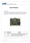
Chapter 1.6 MultiBay Expansion Base and MultiBay ISA Expansion Base Components
The external components on the front and right sides of the expansion base
are shown in Figure 1-4 and described in Table 1-7.
Table 1-7. Expansion Base Components - Front and Right Sides
===========================================================================
Item
Description
===========================================================================
1
Monitor support cover slots
2
External options connector
3
Stereo speakers (MultiBay Expansion Base model)
4
MultiBay II device release button
5
MultiBay II
6
PC Card release buttons
7
Ventilation exhausts (MultiBay ISA Expansion Base model)
8
PC Card slots
9
ISA slot access door (MultiBay ISA Expansion Base model)
10
Stereo speaker (MultiBay ISA Expansion Base model)
11
Security cable slot
12
Docking lever
13
Audio bass port (MultiBay ISA Expansion Base model)
14
Battery lights
15
Docking aid
===========================================================================
Additional components on the front of the expansion base and the
components on the left side of the expansion base are shown in Figure 1-5
and described in Table 1-8.
Table 1-8. Expansion Base Components - Front and Left Sides
===========================================================================
Item
Description
===========================================================================
1
MultiBay I device release button
2
MultiBay I
3
Docking sensor probe
4
Stereo speakers (MultiBay Expansion Base model)
5
Alignment guide
6
Power light
7
Power button
8
Infrared port
9
MultiBay drive lights
10
Audio bass port (MultiBay ISA Expansion Base model)
11
Stereo speaker (MultiBay ISA Expansion Base model)
12
Ventilation exhaust (MultiBay ISA Expansion Base model)
13
AC power connector
===========================================================================
The external components on the rear panel of the expansion base are shown
in Figure 1-6 and described in Table 1-9.
Table 1-9. Expansion Base Components - Rear Panel
===========================================================================
Item
Description
===========================================================================
1
External mouse connector
2
External keyboard connector
3
Stereo speaker/headphone jack
4
Stereo line in jack
5
Ethernet RJ-45 connector
6
Ethernet BNC connector
7
MIDI/Game connector
8
External monitor connector
9
Parallel connector
10
Serial connector
11
Auxiliary fan (MultiBay ISA Expansion Base model)
12
MPEG and TV Video Adapter connector
13
ISA slot cover (MultiBay ISA Expansion Base model)
===========================================================================
Chapter 1.7 Design Overview - MultiBay Expansion Base and MultiBay ISA Expansion Base
In addition to replicating the computer I/O panel and offering additional
mass storage device bays, the expansion bases include the following:
o Main board with integrated Ethernet
o MultiBay connector board
o Power supply
o IrDA interface
o Activity lights
o MultiBays with ejectors
o PC Card slots
o ISA expansion board slot (MultiBay ISA Expansion Base model)
o Computer docking mechanism
1.7.1 Main Board
The expansion base main board supports the following major components:
o Ethernet controller (National DP83907)
o PCMCIA controller (Cirrus 6722)
o Super I/O (National 87334)
o Power controller (TMP47P440AF)
The Ethernet controller supports an integrated 10MB/sec Ethernet
subsystem with 10BaseT and 10Base2 interfaces. The Super I/O component
supports the MultiBays.
1.7.2 MultiBay Connector Board
The MultiBay connector board is mounted between the two MultiBays and
serves to route the appropriate signals to the MultiBay connectors.
1.7.3 Power Supply
The power supply is an AC-to-DC converter that serves the same function as
the AC adapter and DC-to-DC converter in the computer. It provides
regulated DC power for all of the subsystems. The expansion base uses a
standard AC power cord that connects directly to the power supply.
An external fan mounted on the power supply provides cooling. When the
temperature of the power supply exceeds 104oF (40oC), the fan turns on.
When the temperature drops below 104oF, the fan turns off.
The MultiBay ISA model has an auxiliary cooling fan mounted on the rear of
the bottom case. The auxiliary fan remains active as long as power is
applied to the MultiBay ISA Expansion Base.
1.7.4 IrDA Interface
The IrDA interface is mounted on the front left corner of the expansion
base and shares a small PCB with the removable drive status lights. The
board is mounted to the underside of the expansion base top cover with a
single screw. The IrDA interface on the expansion base replicates the IrDA
interface on the computer.
1.7.5 Activity Lights
The expansion base has two sets of activity lights.
Removable-Drive Lights
The removable-drive lights are installed on the front left of the
expansion base and share a small PCB with the IrDA interface. The board is
installed as a unit from the back side of the expansion base top cover.
The status lights are identified in Figure 1-7 and described in Table
1-10.
Table 1-10. Removable Drive Lights
===========================================================================
Index
Function
Description
===========================================================================
1
Computer diskette drive light
Diskette drive in computer MultiBay
is being accessed
2
Computer hard drive/CD-ROM
drive light
Hard drive or CD-ROM drive in
computer is being accessed
3
MultiBay hard drive/CD-ROM
drive light
Hard drive or CD-ROM in one of the
expansion base MultiBays is being
accessed.
4
MultiBay diskette drive light
Diskette drive in one of the
expansion base MultiBays is being
accessed
===========================================================================
Battery Lights
The battery lights are installed on the front right of the expansion base
and share a small PCB with the power button and power light. The board is
installed as a unit from the back side of the expansion base top cover.
The battery lights are identified in Figure 1-8 and described in Table
1-11.
Table 1-11. Battery Lights
===========================================================================
Index
Function
Description
===========================================================================
1
Computer MultiBay battery
Status of battery pack in computer
light
MultiBay
2
Computer battery light
Status of battery pack in computer
battery compartment
3
MultiBay II battery light
Status of battery in MultiBay on
the right side of the expansion
base
4
MultiBay I battery light
Status of battery in MultiBay on
the left side of the expansion
base
===========================================================================
1.7.6 MultiBays with Ejectors
Each expansion base has two MultiBays. Each MultiBay is removable as a
unit with its ejector mechanism. The MultiBay is held to the expansion
base cover with three screws. The MultiBays in the expansion base
accommodate the same drives that are used by the computer and can be used
to charge batteries. MultiBay I will accept Compaq LTE Elite hard drives.
1.7.7 PC Card Slots
Each expansion base has two Type III PC Card slots
to the PC card slots on the computer. Each PC Card
base supports one Type I, one Type II, or one Type
serviceable part of the PC card slots are the slot
connectors are incorporated into the main board.
that function similarly
slot on the expansion
III PC Card. The only
doors. The rails and
1.7.8 Computer Docking Mechanism
The computer docking mechanism has a lever that protrudes from the right
side of either expansion base and serves to aid in seating the computer
when it is pushed toward the rear of the expansion base. The lever
releases the computer from the expansion base when it is pushed toward the
front of the expansion base.
1.7.9 ISA Expansion Board
The MultiBay ISA Expansion Base provides one slot for an 8- or 16-bit,
full-length industry-standard (ISA) expansion board.
The following provisions must be considered when choosing the type of ISA
expansion board to be installed in the expansion base:
o The enhanced video performance of the Compaq LTE 5000 Family of Personal
Computers drives an external monitor at resolutions up to 1024 x 768 x
256 colors and at selectable refresh rates up to 72 Hz, making the use
of ISA graphics controller boards unnecessary. If an ISA graphics
controller card is installed, the system will not operate. Graphics
controller boards are not supported.
o If a National NE2000 or compatible network ISA board is installed, the
built-in ethernet connectors in the expansion base are disabled. To
re-enable the built-in ethernet network feature, the NE2000 or
compatible network ISA expansion board must be removed.
Two Network Interface Cards (NICs) can be enabled at one time as long as
both are not NE2000 or compatible.
NOTE: NICs that have a default address of 300h require setup
configuration changes because the built-in ethernet uses the 300h
address.
o Some Moving Picture Experts Group (MPEG) ISA boards cannot be installed
as they require connection to the "feature connector" of the graphics
controller. This feature connector is not provided on the MultiBay ISA
Expansion Base. MPEG ISA boards with a standard video port (external
monitor connector) that do not require connection to the feature
connector on the graphics controller should function satisfactorily.
The Compaq MPEG and TV Video Adapter option provides enhanced MPEG
capabilities for use with the Compaq LTE 5000 Family of Personal
Computers. To achieve maximum MPEG functionality support, use the Compaq
MPEG and TV Video Adapter option.
o Due to the vast numbers of ISA expansion boards that are available,
Compaq does not guarantee or support every ISA expansion board.
Refer to the documentation accompanying the ISA expansion board being
installed for complete installation and configuration instructions.
Chapter 2. Troubleshooting
Chapter 2.0 Introduction
This chapter contains troubleshooting information for the computer. The
basic steps in troubleshooting include:
1. Completing the preliminary steps listed in Section 2.1.
2. Running the Power-On Self-Test (POST) as described in Section 2.4.
3. Running the Computer Checkup (TEST) as described in Section 2.5.
4. Performing the recommended actions described in the diagnostic tables
in Section 2.7 if you are unable to exercise POST or Computer Checkup
or if the problem persists after running POST and Computer Checkup.
Adhere to the following guidelines when troubleshooting:
o Complete the recommended actions in the order in which they are given.
o Repeat POST and Computer Checkup after each recommended action until the
problem is resolved and the error message does not return.
o Once the problem is resolved, do not complete the remaining recommended
actions.
o Refer to Chapter 5 for any removal and replacement procedures that are
recommended.
Chapter 2.1 Preliminary Steps
IMPORTANT: Use the AC adapter when running POST, Computer Setup, or
Computer Checkup. A low battery condition could initiate
Standby (Suspend) and interrupt the test.
Before running POST and Computer Checkup, complete the following steps:
1. If a power-on password has been established, type the password and
press Enter.
NOTE: The key icon appears on the status display when the computer is
turned on to indicate that QuickLock/QuickBlank has been initiated.
Type the power-on password to exit QuickLock/QuickBlank. If the
password is unknown, it must be cleared (see Section 2.2).
2. Run Computer Setup (Section 2.3).
3. Position the brightness control actuator and contrast control actuator
(on selected models) in the center of their ranges and leave the
display open.
4. Turn off the computer and all external devices.
5. Disconnect any external devices that you do not want to test. If you
want to use the printer to log error messages, leave it connected to
the computer.
NOTE: If a problem only occurs when an external device is connected to the
computer, the problem could be with the external device or its
cable. Isolate the problem by running POST with and without the
external device connected.
6. Use Advanced Diagnostics and loopback plugs in the serial and parallel
connectors if you plan to test these ports. To run Advanced
Diagnostics, complete the following steps:
a. Insert the Diagnostics diskette into the diskette drive and turn on
the computer.
b. At the Welcome Screen, press Ctrl + A.
c. Press Enter to accept OK.
d. Select Computer Checkup (TEST).
e. Select Prompted Diagnostics after "Identifying System Hardware"
completes.
f. Select Interactive Testing and follow the displayed instructions.
Refer to Chapter 3 for description and spare part number for the loopback
plugs.
7. Ensure that the primary hard drive is installed in the computer.
8. Ensure that the battery pack is installed in the computer and the AC
Adapter is connected to the computer and plugged into an AC power
source.
After completing the preliminary steps, run POST (Section 2.4) and
Computer Checkup (Section 2.5).
Chapter 2.2 Clearing the Power-On and Setup Passwords
The power-on password prevents use of the computer until the password is
entered. The setup password prevents unauthorized changes to Computer
Setup. To clear the passwords, you must remove and replace a jumper on the
system board. If you do not know the passwords, use the following
procedure to clear the password:
1. Complete the preparation for disassembly procedures in Section 5.3.
2. Remove the CPU cover as described in Section 5.5.
3. Move the jumper on JP1 (Figure 2-1) from pins 2 and 3 to pins 1 and 2.
4. Turn on the computer and run POST.
5. Turn off the computer and move the JP1 jumper to pins 2 and 3 for
normal operation.
Chapter 2.3 Running Computer Setup
The ROM-based Computer Setup displays the current system configuration and
allows you to set system and power management parameters. These parameters
are stored in CMOS, and a backup copy is saved in a parameter block in
system flash ROM.
You can access Computer Setup by pressing F10 when the prompt appears
after you turn on or restart the computer. The following configuration
parameters can be changed in Computer Setup:
o Date and time
o Power conservation (when)
o Power conservation (level)
o PC Card slot power management
o Hibernation on/off
o Hibernation settings
o Warning beep
o Setup password
o Diskette drive disable
o Serial/IrDA ports disable
o Parallel port disable
o PC Card slots disable
o Resume password on/off
o Boot memory test
o Keyboard numlock
o Boot sequence
o Boot display
o Serial port settings
o Infrared port settings
o Parallel port settings
o Power-on password
o Diskette drive boot disable
o NTSC/PAL
o Windows 95 Power Properties
o Lid closure notification
o Advanced LPT mode
Computer Setup automatically recognizes and configures the system for new
Compaq devices. It does this without prompting you for information about
the devices. However, if you add a memory expansion board, the next time
you turn on the computer a prompt appears notifying you of the new memory
configuration.
The first Computer Setup screen displays current settings for the system,
ports, and devices. The status bar at the bottom of the screen gives
instructions for navigating and choosing options. The status bar also
displays descriptions as you highlight menus and menu options.
NOTE: If the main system board is replaced, the serial number on this
screen changes to 0 (zero).
Select one of the menus from the menu bar at the top of the screen to view
or to change the following configuration settings:
o Initialization startup preferences
o Ports, including serial/infrared, parallel, Ethernet, and MPEG
o Power, including Power Management and Hibernation
o Security, including setup and power-on passwords and disabling devices
2.3.1 Initialization Menu
Select the Initialization menu to set the date and time and to change the
initialization (startup) settings for running the POST memory tests,
numlock on or off, the drive boot sequence, boot display, and lid closure
notification.
NOTE: The boot sequence sets the order in which the system searches for a
bootable drive to start the computer. Before changing the booting
sequence, see "The Hard Drive Boot Sequence" in Appendix C for more
information.
2.3.2 Ports Menu
Select the Ports menu to change the default input/output (I/O) addresses
and interrupt requests (IRQs) for serial/infrared, parallel, and Ethernet
ports, select PAL or NTSC for the optional MPEG video format, and enable
Advanced LPT mode.
NOTE: If you select conflicting settings for the ports, the system
automatically changes one of the settings.
2.3.3 Power Menu
Select the Power menu to enable or disable Power Management, PC Card slot
power management (not available on LTE 5000, LTE 5100, and LTE 5200
models), low-battery warning beeps, and an external energy saving monitor.
The factory default settings are:
o Power Management Enabled While on Battery
o Conservation Level Medium
o Low-Battery Warning Beeps Enabled
o External Energy Saving Monitor Disabled
o PC Card Power Off During Standby
>>>>>>>>>>>>>>>>>>>>>>>>>>>>>>>>> CAUTION <<<<<<<<<<<<<<<<<<<<<<<<<<<<<<<<<
If you disable Power Management or Hibernation, you must take immediate
action to resolve a low-battery condition to prevent losing unsaved
information.
>>>>>>>>>>>>>>>>>>>>>>>>>>>>>>>>>>>>><<<<<<<<<<<<<<<<<<<<<<<<<<<<<<<<<<<<<<
If you select to disable the low-battery warning beeps, a low-battery
condition is indicated only by a blinking battery light. If you disable
Power Management or Hibernation, information in memory is not
automatically saved during a critical low-battery condition.
If you enable the selection for an external energy saving monitor, it
enters low-power mode when the screen timeout occurs. If you enable this
selection and you do not have an energy saving monitor, the screen display
may become distorted.
Under PC Card slot power management, resume power to the PC Card slots and
ring reserve feature may be enabled during Standby (Suspend). This feature
is not available on the LTE 5000, LTE 5100, and LTE 5200 models.
Under Power Management, you can select whether to enable Power Management
while on AC or battery power, only while on battery power, or never
(disabled).
If you enable Power Management, you can select the conservation level:
high, medium, or custom. The conservation level sets the timeouts for
Standby (Suspend), Hibernation, drives, and screens.
A timeout is a period of inactivity after which power is turned off to the
system or component. Refer to Chapter 7 for more information about Standby
(Suspend) and Hibernation.
o High: - Provides the maximum amount of power conservation and the
maximum battery operating time from a single charge.
o Medium (default): - Provides a balance between performance and battery
life.
o Custom: - Conserves power according to specified timeout settings.
NOTE: Selecting to disable the infrared port under the Security menu also
conserves power.
Windows 95 Power Properties
To open the Windows 95 Power Properties dialog box, double click the Power
icon in Control Panel. Windows 95 provides the following options:
o Advanced (default) - Activates power management settings in Computer
Setup and provides some additional power-saving features.
o Standard - Activates the settings in Computer Setup.
o Off - Turns off all power management. The power management icon on the
status panel turns off.
NOTE: You can also temporarily toggle power management off and on by
pressing the Fn+F7 hotkeys. The next time you restart the computer,
the Power Properties setting takes effect.
2.3.4 Security Menu
Select the Security menu to set, change, or delete the setup and power-on
passwords, and to enable/disable QuickLock/QuickBlank, power-on password
from Standby, diskette drives, ports, and PC Card slots.
Setup Password
Use the Setup password to protect the system configuration from
unauthorized changes. After you establish the setup password, you cannot
change the system configuration until you enter the setup password.
IMPORTANT: Type carefully because the password does not display as you
type it. If you choose to, you can use the same password for
setup and for power-on.
The next time you press F10 (after POST) to run Computer Setup, a password
prompt appears on the screen. If you enter the password incorrectly, you
are prompted to reenter the password.
If you forget your setup password, you cannot change the system
configuration until the computer memory is cleared of the password.
>>>>>>>>>>>>>>>>>>>>>>>>>>>>>>>>> CAUTION <<<<<<<<<<<<<<<<<<<<<<<<<<<<<<<<<
Record your setup password and put it in a safe place. If you forget your
setup password, you cannot reconfigure the computer until the computer
memory is cleared of the password.
>>>>>>>>>>>>>>>>>>>>>>>>>>>>>>>>>>>>><<<<<<<<<<<<<<<<<<<<<<<<<<<<<<<<<<<<<<
Power-On Password
The power-on password prevents use of the computer until the password is
entered. After you establish the power-on password, you must enter it
whenever you turn on the computer.
IMPORTANT: Type carefully because the password does not display as you
type it. If you choose to, you can use the same password for
setup and for power-on.
You can also select to require the power-on password when exiting Standby
(Suspend).
The next time you start the computer or exit Standby (Suspend), a password
prompt appears. If you enter the password incorrectly, you are prompted to
reenter the password.
If you forget your power-on password, you cannot use the computer until
the computer memory is cleared of the password.
>>>>>>>>>>>>>>>>>>>>>>>>>>>>>>>>> CAUTION <<<<<<<<<<<<<<<<<<<<<<<<<<<<<<<<<
Record your power-on password and put it in a safe place. If you forget
your power-on password, you cannot use the computer until the computer
memory is cleared of the password.
>>>>>>>>>>>>>>>>>>>>>>>>>>>>>>>>>>>>><<<<<<<<<<<<<<<<<<<<<<<<<<<<<<<<<<<<<<
QuickLock/QuickBlank
Enabling QuickLock/QuickBlank allows you to temporarily disable the
keyboard and clear the screen until the power-on password is entered.
After you have enabled QuickLock/QuickBlank, you can initiate it at any
time by pressing the Fn+F6 hotkeys.
When QuickLock/QuickBlank is initiated, the key icon on the status panel
turns on. Type your power-on password on the blank screen to exit
QuickLock/QuickBlank.
Disabling Devices
The Security Menu provides a way to disable the following devices:
o Serial and infrared ports
o Parallel port
o PC Card slots
o Diskette drive
Disabling these devices prevents the unauthorized transfer of data using
the devices. Disabling the infrared port also conserves power. To reenable
a device, deselect the Disable option and restart the computer.
2.3.5 Exit Menu
The Exit menu has three options:
o Save and Exit: Saves configuration changes, but some changes do not take
effect until the computer is restarted.
o Exit (No Save): Exits and does not save the changes you have made.
o Restore Factory Defaults: Replaces the current configuration settings
with the original factory default settings.
Chapter 2.4 POST Error Messages
This chapter contains typical error messages that you may encounter during
the power-on self-test (POST). POST is a series of tests that run every
time you turn on the computer. POST verifies that the system is configured
and functioning properly. A successful POST is followed by one or two
short beeps.
If you receive an error message listed below, follow the recommended
action. If you receive an error message that is not listed, contact your
Compaq authorized service provider. You may also want to run Computer
Checkup from the Diagnostics diskette. Information about running Computer
Checkup is presented later in this section.
If POST detects an error, one of the following events occurs:
o A message with the prefix "WARNING" appears informing you where the
error occurred. The system pauses until you press F1 to continue.
o A message with the prefix "FATAL" appears informing you where the error
occurred. After the message, the system emits a series of audible beeps.
The system then stops.
o The system emits a series of audible beeps. The system then stops.
Warning messages indicate a potential problem exists such as a system
configuration error. When F1 is pressed, the system should resume. You
should be able to correct problems that produce WARNING messages.
IMPORTANT: When a WARNING message includes the prompt to "RUN SCU," run
Computer Setup. (Computer Setup replaces the SCU utility.)
Fatal errors emit a beep and may display a FATAL message. Fatal errors
indicate severe problems, such as a hardware failure. Fatal errors do not
allow the system to resume. Some of the Fatal error beep codes are listed
at the end of this section.
Table 2-1. Warning Messages
===========================================================================
Message
Description
===========================================================================
Clock not ticking correctly
The real time clock is not ticking.
--------------------------------------------------------------------------CMOS checksum invalid, run
CMOS RAM information has been corrupted and
SCU
needs to be reinitialized by running Computer
Setup.
--------------------------------------------------------------------------CMOS failure, run SCU
CMOS RAM has lost power and needs to be
reinitialized by running Computer Setup.
--------------------------------------------------------------------------Floppy controller failed
The diskette drive controller failed to
respond to the reset command. Power down the
system and check all appropriate connections.
If the diskette drive controller continues to
fail, you may need to replace the system
board.
---------------------------------------------------------------------------
Floppy disk track 0 failed
The diskette drive cannot read track 0 of the
diskette in the drive. Try another diskette.
If the problem persists, you may need to
replace the diskette drive.
--------------------------------------------------------------------------Floppy information invalid,
The drive parameters stored in CMOS RAM do
run SCU
not match the diskette drives detected in the
system.
--------------------------------------------------------------------------Hard disk controller error
The hard drive controller failed to respond
to the reset command. Check the drive
parameters. Power down the system and check
all appropriate connections.
--------------------------------------------------------------------------Hardware information does
The video adapter type specified in CMOS RAM
not match video card, run
does not match the installed hardware.
SCU
--------------------------------------------------------------------------Keyboard controller failure
The keyboard failed the self-test command.
--------------------------------------------------------------------------Keyboard failure
The keyboard failed to respond to the RESET
ID command.
--------------------------------------------------------------------------No interrupts from Timer 0
The periodic timer interrupt is not
occurring.
--------------------------------------------------------------------------RAM parity error at
A RAM parity error occurred at the specified
location xxxx
(hex) location.
--------------------------------------------------------------------------ROM at xxxx (LENGTH yyyy)
An illegal adapter ROM was located at the
with nonzero checksum (zz)
specified address. An external adapter (such
as a video card) may be causing the conflict.
--------------------------------------------------------------------------Time/Date corrupt - run SCU
The time and date stored in the real time
clock have been corrupted, possibly by a
power loss.
--------------------------------------------------------------------------Unexpected amount of
The amount of memory detected by POST does
memory, run SCU
not match the amount specified in CMOS RAM.
--------------------------------------------------------------------------Hard disk xx failure
A failure or an error occurred when trying to
(or error)
access the hard drive.
===========================================================================
Table 2-2. Fatal Error Messages
===========================================================================
Message
Description
Beep Code
===========================================================================
CMOS RAM test failed
A walking bit test of CMOS RAM
3
location 0E (Hex) - 3F (Hex) failed.
--------------------------------------------------------------------------DMA controller faulty
A sequential read/write of the
4
transfer count and transfer address
registers within the primary and
secondary DMA controllers failed.
--------------------------------------------------------------------------Faulty DMA page
A walking bit read/write of the 16 DMA
0
registers
controller page registers starting at
location 80 Hex failed.
---------------------------------------------------------------------------
Faulty refresh
circuits
A continuous read/write test of port
1
61h found that bit 4 (Refresh Detect)
failed to toggle within an allotted
amount of time.
--------------------------------------------------------------------------Interrupt controller
A sequential read/write of various
5
failed
Interrupt Controller registers failed.
--------------------------------------------------------------------------ROM checksum incorrect
A checksum of the ROM BIOS does not
2
match the byte value at F000:FFFF.
--------------------------------------------------------------------------RAM error at location
RAM error occurred during memory test.
None
xxxx
--------------------------------------------------------------------------Parity error at
Parity error occurred.
None
unknown location
===========================================================================
The following table lists some of the Fatal Error beep codes, along with
the beep sequence (short, long, pause) and the meaning of the beeps.
Table 2-3. Fatal Error Beep Codes
===========================================================================
Beep Code
Beep Sequence
Explanation
Remedy
===========================================================================
0
S-S-S-P-S-S-L-P
The DMA page
Replace system board.
registers are faulty.
1
S-S-S-P-S-L-S-P
The refresh circuitry
is faulty.
Replace system board.
2
S-S-S-P-S-L-L-P
The ROM checksum is
incorrect.
1. Flash the ROM
2. Replace system
board.
3
S-S-S-P-L-S-S-P
The CMOS RAM test
failed.
Replace system board.
4
S-S-S-P-L-S-L-P
The DMA controller is
faulty.
Replace system board.
5
S-S-S-P-L-L-S-P
The interrupt
controller failed.
Replace system board.
6
S-S-S-P-L-L-L-P
The keyboard
controller failed.
Replace system board.
7
S-S-L-P-S-S-S-P
Graphics adapter is
faulty.
Replace system board.
8
S-S-L-P-S-S-L-P
Internal RAM is
Replace processor
faulty.
board.
--------------------------------------------------------------------------S = Short, L = Long, P = Pause
===========================================================================
Chapter 2.5 Compaq Diagnostics
A Compaq Diagnostics diskette is supplied with the computer. Run the
Diagnostics utilities when you want to view or test system information and
installed or connected devices. The Diagnostics menu includes the
following utilities:
o Computer Checkup (TEST)
o View System Information (INSPECT)
If you have a problem you cannot solve, run the Diagnostics utilities
before you call for support. Run Computer Checkup and select to save the
device list to a file and to print or to save the log of errors. Run the
View System Information (INSPECT) utility and select to print or to save
that information. Have the files or the printed information available when
you call for support.
2.5.1 Computer Checkup (TEST)
Computer Checkup (TEST) determines whether the various computer components
and devices are recognized by the system and are functioning properly. You
can display, print, or save the information generated by Computer Checkup.
Follow these steps to run Computer Checkup:
1. Plug the computer into an external power source. (A low battery
condition could interrupt the program.)
2. Turn on the external devices that you want to test. Connect the
printer if you want to print a log of error messages.
3. Insert the Compaq Diagnostics diskette in drive A.
4. Turn on or restart the computer. The computer starts from drive A, and
the Diagnostics Welcome screen appears.
5. Press Enter to continue. The Diagnostics menu appears.
6. Select Computer Checkup from the Diagnostics menu. A Test Option menu
appears.
7. Select "View the Device List" from the Test Option menu. A list of the
installed Compaq devices appears.
8. If the list of installed devices is correct, select OK. The Test
Option menu appears.
NOTE: If the list is incorrect, ensure that any new devices are
installed properly.
9. Select one of the following from the Test Option menu:
o Quick Check Diagnostics. Runs a quick, general test on each device
with a minimal number of prompts. If errors occur, they display when
the testing is complete. You cannot print or save the error
messages.
o Automatic Diagnostics. Runs unattended, maximum testing of each
device with minimal prompts. You can choose how many times to run
the tests, to stop on errors, or to print or save a log of errors.
o Prompted Diagnostics. Allows maximum control over testing the
devices. You can choose attended or unattended testing, decide to
stop on errors, or choose to print or save a log of errors.
10. Follow the instructions on the screen as the devices are tested. When
testing is complete, the Test Option menu appears.
11. Exit the Test Option menu.
12. Exit the Diagnostics menu.
2.5.2 View System Information (INSPECT)
The View System Information (INSPECT) utility provides information about
the computer and installed or connected devices. You can display, print,
or save the information.
Follow these steps to run View System Information (INSPECT) from the
Compaq Diagnostics diskette:
1. Turn on the external devices that you want to test. Connect the printer
if you want to print the information.
2. Insert the Compaq Diagnostics diskette in drive A.
3. Turn on or restart the computer. The computer starts from drive A, and
the Diagnostics Welcome screen appears.
4. Press Enter to continue. The Diagnostics menu appears.
5. Select View System Information (INSPECT) from the Diagnostics menu.
6. Select the item you want to view from the following list:
===========================================================================
System
Memory
ROM
Audio
Keyboard
Operating system
System ports
System files
System storage
Windows files
Graphics
===========================================================================
7. Follow the instructions on the screen to cycle through the screens, to
return to the list and choose another item, or to print the
information.
Chapter 2.6 Diagnostic Error Codes
Diagnostic error codes occur if the system recognizes a problem while
running the Compaq Diagnostic program. These error codes help identify
possibly defective subassemblies.
Tables 2-4 through 2-16 list possible error codes, a description of the
error condition, and the action required to resolve the error condition.
IMPORTANT: Retest the system after completing each step. If the problem
has been resolved, do not proceed with the remaining steps.
For assistance in the removal and replacement of a particular subassembly,
see Chapter 5, "Removal and Replacement Procedures."
Table 2-4. Processor Test Error Codes
===========================================================================
Error Code
Description
Recommended Action
===========================================================================
101 - xx
CPU test failed
Replace the processor board and retest.
--------------------------------------------------------------------------102 - xx
Coprocessor or
1. Run the Configuration and
Weitek Error
Diagnostics Utilities.
2. Replace the processor board and
retest.
--------------------------------------------------------------------------103 - xx
DMA page registers
Replace the system board and retest.
test failed
104 - xx
Interrupt controller
master test failed
105 - xx
Port 61 error
106 - xx
Keyboard controller
self-test failed
107 - xx
CMOS RAM test
failed
108 - xx
CMOS interrupt test
failed
109 - xx
CMOS clock test
failed
110 - xx
Programmable timer
load data test
failed
113 - xx
Protected mode test
failed
--------------------------------------------------------------------------114 - 01
Speaker test failed
1. Check system configuration.
2. Verify cable connections to speaker.
3. Replace the system board and retest.
===========================================================================
Table 2-5. Memory Test Error Codes
===========================================================================
Error Code
Description
Recommended Action
===========================================================================
200 - xx
Memory machine ID
The following steps apply to error
test failed
codes 200 - xx and 202 - xx:
202 - xx
Memory system ROM
1. Flash the system ROM and retest.
checksum failed
2. Replace the system board and retest.
--------------------------------------------------------------------------203 - xx
Write/Read test
The following steps apply to error
failed
codes 203 - xx through 215 - xx:
204 - xx
Address test failed
211 - xx
Random pattern test
failed
214 - xx
Noise test failed
1. Remove the memory module and retest.
2. Install a new memory module and
retest.
215 - xx
Random address test
failed
===========================================================================
Table 2-6. Keyboard Test Error Codes
===========================================================================
Error Code
Description
Recommended Action
===========================================================================
300 - xx
Failed ID Test
The following steps apply to error
codes 300 - xx through 304 - xx:
301 - xx
Failed Self-test/
Interface Test
302 - xx
Failed Individual
Key Test
1. Check the keyboard connection. If
disconnected, turn off the computer
and connect the keyboard.
2. Replace the keyboard and retest.
3. Replace the system board and retest.
304 - xx
Failed Keyboard
Repeat Test
===========================================================================
Table 2-7. Parallel Printer Test Error Codes
===========================================================================
Error Code
Description
Recommended Action
===========================================================================
401 - xx
Printer failed or
The following steps apply to error
not connected
402 - xx
codes 401 - xx through 403 - xx:
Failed Port Test
1. Connect the printer.
2. Check power to the printer.
403 - xx
Printer pattern test
3. Install the loopback connector and
failed
retest.
4. Check port and IRQ configuration.
5. Replace the system board and retest.
===========================================================================
Table 2-8. Diskette Drive Test
===========================================================================
Error Code
Description
Recommended Action
===========================================================================
600 - xx
Diskette ID drive
The following steps apply to error
types test failed
codes 600 - xx through 698 - xx:
601 - xx
Diskette format
failed
602 - xx
Diskette read test
failed
603 - xx
Diskette write,
read, compare test
failed
604 - xx
Diskette random
read test failed
605 - xx
Diskette ID media
failed
606 - xx
Diskette speed test
failed
609 - xx
Diskette reset
controller test
failed
610 - xx
Diskette change
line test failed
697 - xx
Diskette type error
1. Replace the diskette media and
retest.
2. Check and/or replace the diskette
power and signal cables and retest.
3. Replace the diskette drive and
retest.
4. Replace the system board and
retest.
698 - xx
Diskette drive speed
not within limits
--------------------------------------------------------------------------699 - xx
Diskette drive/media
1. Replace media.
ID error
2. Run the Configuration and
Diagnostics Utilities.
===========================================================================
Table 2-9. Serial Test Error Codes
===========================================================================
Error Code
Description
Recommended Action
===========================================================================
1101 - xx
Serial port test
1. Check port configuration
failed
2. Replace the system board and retest.
===========================================================================
Table 2-10. Hard Drive Test Error Codes
===========================================================================
Error Code
Description
Recommended Action
===========================================================================
1701 - xx
Hard drive format
The following steps apply to error
test failed
codes 1701 - xx through 1736 - xx:
1702 - xx
Hard drive read test
failed
1703 - xx
Hard drive write/
read/compare test
failed
1704 - xx
Hard drive random
seek test failed
1705 - xx
Hard drive
controller test
failed
1706 - xx
Hard drive ready
test failed
1707 - xx
Hard drive
recalibration test
failed
1708 - xx
Hard drive format
bad track test
failed
1709 - xx
Hard drive reset
controller test
failed
1710 - xx
Hard drive park
head test failed
1715 - xx
Hard drive head
select test failed
1716 - xx
Hard drive
conditional format
test failed
1717 - xx
Hard drive ECC *
test failed
1719 - xx
Hard drive power
mode test failed
1724 - xx
Network preparation
test failed
1736 - xx
1. Run the Configuration and
Diagnostics Utilities and verify
drive type.
2. Verify that all secondary drives
have secondary drive capability
(see Appendix C).
3. Replace the hard drive and retest.
4. Replace the system board and retest.
Drive monitoring
test failed
---------------------------------------------------------------------------
* ECC = Error Correction Code
===========================================================================
Table 2-11. Video Test Error Codes
===========================================================================
Error Code
Description
Recommended Action
===========================================================================
501 - xx
Video controller
The following apply to error codes
test failed
501 - xx through 516 - xx:
502 - xx
Video memory test
failed
503 - xx
Video attribute test
failed
504 - xx
Video character set
test failed
505 - xx
Video 80 x 25
mode 9 x 14
character cell test
failed
506 - xx
Video 80 x 25 mode
8 x 8 character
cell test failed
507 - xx
Video 40 x 25 mode
test failed
508 - xx
Video 320 x 200
mode color set 0
test failed
509 - xx
Video 320 x 200
mode color set 1
test failed
510 - xx
Video 640 x 200
mode test failed
511 - xx
Video screen memory
page test failed
512 - xx
Video gray scale
test failed
514 - xx
Video white screen
test failed
1. Disconnect external monitor and test
with internal LCD display.
2. Check display jumpers on the
processor board (see Chapter 5)
3. Replace the display assembly and
retest.
4. Replace the system board and retest.
516 - xx
Video noise pattern
test failed
--------------------------------------------------------------------------Error Code
Description
Recommended Action
--------------------------------------------------------------------------2402 - xx
Video memory test
The following steps apply to error
failed
codes 2402 - xx through 2456 - xx:
2403 - xx
Video attribute test
1. Run the Configuration and
failed
2404 - xx
Video character set
test failed
2405 - xx
Video 80 x 25 mode
9 x 14 character
cell test failed
2406 - xx
Video 80 x 25 mode
8 x 8 character
cell test failed
2408 - xx
Video 320 x 200
mode color set 0
test failed
2409 - xx
Video 320 x 200
mode color set 1
test failed
2410 - xx
Video 640 x 200
mode test failed
2411 - xx
Video screen
memory page test
failed
2412 - xx
Video gray scale
test failed
2414 - xx
Video white screen
test failed
2416 - xx
Video noise
pattern test
failed
Diagnostics Utilities.
2. Replace the display assembly and
retest.
3. Replace the system board and retest.
2418 - xx
ECG/VGC memory
test failed
--------------------------------------------------------------------------Error Code
Description
Recommended Action
--------------------------------------------------------------------------2419 - xx
ECG/VGC ROM checksum
The following steps apply to error
test failed
codes 2402 - xx through 2456 - xx:
2421 - xx
ECG/VGC 640 x 200
graphics mode test
failed
2422 - xx
ECG/VGC 640 x 350
16 color set test
failed
2423 - xx
ECG/VGC 640 x 350
64 color set test
failed
2424 - xx
ECG/VGC monochrome
text mode test
1. Run the Configuration and
Diagnostics Utilities.
2. Disconnect external monitor and
test with internal LCD display.
3. Check display jumpers on the
processor board (see Chapter 5.)
4. Replace the display assembly and
retest.
5. Replace the system board and retest.
failed
2425 - xx
ECG/VGC monochrome
graphics mode test
failed
2431 - xx
640 x 480 graphics
test failure
2432 - xx
320 x 200 graphics
(256 color mode)
test failure
2448 - xx
Advanced VGA
Controller test
failed
2451 - xx
132-column Advanced
VGA test failed
2456 - xx
Advanced VGA 256
Color test failed
--------------------------------------------------------------------------2458 - xx
Advanced VGA BitBLT
Replace the system board and retest.
test
2468 - xx
Advanced VGA DAC
test
2477 - xx
Advanced VGA data
path test
2478 - xx
Advanced VGA BitBLT
test
2480 - xx
Advanced VGA
Linedraw test
===========================================================================
Table 2-12. Audio Test Error Codes
===========================================================================
Error Code
Description
Recommended Action
===========================================================================
3206 - xx
Audio System
Replace the system board and retest.
Internal Error
===========================================================================
Table 2-13. Pointing Device Interface Test Error Codes
===========================================================================
Error Code
Description
Recommended Action
===========================================================================
8601 - xx
Mouse test failed
The following steps apply to 8601 - xx
and 8602 - xx:
8602 - xx
Interface test
failed
1. Replace the EasyPoint II controller
board and retest.
2. Replace the system board and retest.
===========================================================================
Table 2-14. CD-ROM Test Error Codes
===========================================================================
Error Code
Description
Recommended Action
===========================================================================
3301 - xx
CD-ROM drive read
The following steps apply to error
test failed
codes 3301 - xx through 3305 - xx and
6600 - xx through 6623 - xx:
3305 - xx
CD-ROM drive seek
test failed
6600 - xx
ID test failed
6605 - xx
Read test failed
6608 - xx
Controller test
failed
1. Replace the CD and retest.
2. Verify that the speakers are
connected.
3. Verify that drivers are loaded and
properly installed.
4. Replace the CD-ROM drive and
retest.
5. Replace the system board and
retest.
6623 - xx
Random read test
failed
===========================================================================
Chapter 2.7 Troubleshooting Without Diagnostics
This section provides information about how to identify and correct some
common hardware, memory, and software problems. It also explains several
types of common messages that may be displayed on the screen. The
following pages contain troubleshooting information on:
o Audio
o Memory
o Battery/battery gauge
o MultiBay ISA Expansion Base
o CD-ROM drive
o PC Card
o Diskette/diskette drive
o Pointing device
o Hard drive
o Power
o Hardware installation
o Printer
o Infrared connection
o Screen (LCD and CRT)
o Keyboard/numeric keypad
2.7.1 Solving Minor Problems
Some minor problems and possible solutions are outlined in the following
tables. If the problem appears related to a software application, check
the documentation provided with the software.
Solving Audio Problems
Some common audio problems and solutions are listed in the following
table.
Table 2-15. Solving Audio Problems
===========================================================================
Problem
Probable Cause
Solution(s)
===========================================================================
Computer beeps once
This is typical; it
No action is required.
after you turn it
indicates successful
on.
completion of the Power-On
Self-Test (POST).
--------------------------------------------------------------------------Computer does not
Speaker volume is off or
If the speaker icon is
beep after the
has been turned down.
not displayed on the
Power-On Self-Test
status panel, Press
(POST).
Fn+F5 to turn the
speaker on, then adjust
the volume.
Beeps have been turned
Run Computer Setup and
off.
turn on beeps.
--------------------------------------------------------------------------Loss of audio
Moving hard drives between
Download appropriate
different LTE 5000 models
driver from Compaq.
===========================================================================
Solving Battery and Battery Gauge Problems
Some common causes and solutions for battery problems are listed in the
following table. The "Solving Power Problems" section in this chapter also
may be applicable.
Table 2-16. Solving Battery and Battery Gauge Problems
===========================================================================
Problem
Probable Cause
Solution(s)
===========================================================================
Computer won't turn
Battery is discharged.
Connect the computer to
on when battery pack
an external power
is inserted and
source and charge the
power cord is
battery pack.
unplugged.
Replace the battery pack
with a fully charged
battery pack.
Check the battery
connectors on the system
board to verify they are
evenly spaced and that
they are not bent or
broken.
--------------------------------------------------------------------------Computer is beeping
Battery charge is low.
Immediately save any open
and battery light
file(s). Then do any one
is blinking.
of the following:
o Connect the computer to
an external power
source to charge the
battery pack.
o Initiate Standby and
replace the battery
pack with a fully
charged battery pack.
o Turn the computer off
or initiate Hibernation
until you can find
another power source or
charge the battery
pack.
--------------------------------------------------------------------------Computer battery
Low battery beeps
Run Computer Setup to
light blinks to
were turned off.
turn on the low battery
indicate low battery
warning beeps.
condition, but
computer does not
beep.
Volume is turned off or
turned down too low.
Press Fn+F5 to turn the
speaker on and then
adjust the volume.
--------------------------------------------------------------------------Problem
Probable Cause
Solution(s)
--------------------------------------------------------------------------Battery light
Battery pack is already
No action is necessary.
doesn't light and
charged.
battery pack won't
fast charge.
Battery pack was exposed
to temperature extremes.
Allow time for the
battery pack to return to
room temperature.
Battery pack is at end
Replace battery pack.
of its life.
--------------------------------------------------------------------------While the computer
The battery pack was not
Next time, initiate
is in Standby
replaced within 10
Standby, then remove the
(Suspend), computer
minutes. The battery
battery pack and replace
turns off
pack must be replaced
it within 10 minutes.
within 10 minutes to
prevent loss of
information.
Auxiliary battery charge
Provide power (AC or
is low, or the auxiliary
battery is at end of its
life.
battery) to the computer;
this charges the
auxiliary battery.
Replace the auxiliary
battery.
--------------------------------------------------------------------------You have to set the
Auxiliary battery charge
Provide power to the
date and time every
is low, or the auxiliary
computer (AC or battery),
time you turn on
battery is at end of its
which charges the
the computer.
life.
auxiliary battery.
Replace the auxiliary
battery.
--------------------------------------------------------------------------Battery charge does
Battery is being exposed
Keep the battery pack
not last as long as
to high temperatures or
within the recommended
expected.
extremely cold
operating temperature
temperatures.
range 50oF to 104oF (10oC
to 40oC) or recommended
storage range -4oF to
86oF (-20oC to 30oC).
Recharge the battery
pack.
Battery has partially
self-discharged.
Recharge the battery.
Discharge the battery
completely until the
unit powers off, and
then completely recharge
it. Repeat this process
every 30 days.
Power management is
disabled.
Set a power management
level in Computer Setup.
An external device or
PC Card is draining the
battery.
Turn off or disconnect
external devices when not
using them.
Extensive modem usage.
Connect to external
power source when using
CD-ROM extensively.
Extensive operation in
Avoid extensive
DOS mode (power
operation in DOS mode.
management is not
implemented in DOS
mode).
--------------------------------------------------------------------------Battery pack is
Normal warming has
No action is required.
warm to the touch
occurred due to
after charging.
charging.
--------------------------------------------------------------------------Battery gauge is
The battery pack is new
Fully charge the battery
inaccurate.
or has not been used for
pack until the battery
a long period.
light on the computer
turns off.
Condition the battery
pack by fully charging,
then fully discharging
until the unit powers
off, and then fully
recharging again.
===========================================================================
Solving CD-ROM Drive Problems
Some common causes and solutions for CD-ROM drive problems are listed in
the following table.
Table 2-17. Solving CD-ROM Drive Problems
===========================================================================
Problem
Probable Cause
Solution(s)
===========================================================================
CD-ROM drive cannot
Compact disc is upside
Open the CD loading tray,
read a compact disc.
down or is improperly
lay the compact disc in
inserted in the CD-ROM
it (label side up), then
drive.
close the tray.
--------------------------------------------------------------------------CD-ROM drive does
CD-ROM drive is not
Shut down the computer,
not work.
seated properly.
remove and reinsert the
drive, then turn on the
computer.
CD-ROM drive was
Shut down computer; then
inserted while the
turn it on again. The
computer was on, in
drive is initialized
Standby (Suspend), or
during power up.
in Hibernation.
--------------------------------------------------------------------------No sound comes from
You have two CD-ROM
Shut down the computer
a CD-ROM drive in
drives in the expansion
and remove one of the
the expansion base.
base and are trying to
CD-ROM drives from the
play an audio (music)
expansion base. If two
CD on one of them.
CD-ROM drives are in the
expansion base, neither
can play audio (music)
CDs.
===========================================================================
Solving Diskette and Diskette Drive Problems
Some common causes and solutions for diskette and diskette drive problems
are listed in the following table.
Table 2-18. Solving Diskette and Diskette Drive Problems
===========================================================================
Problem
Probable Cause
Solution(s)
===========================================================================
Diskette drive icon
Diskette drive is not
Remove the diskette drive
does not turn on.
installed properly.
and install it properly.
--------------------------------------------------------------------------Cannot access
Real mode device drivers
Remove the check marks
diskette drive in
have not been loaded.
from the docked and
expansion base when
running Windows 95.
undocked configurations
in Standard Floppy Disk
Controller Properties to
unload the protected mode
drivers and then restart
the computer.
--------------------------------------------------------------------------Diskette drive icon
Diskette is damaged.
Run SCANDISK on the
stays on.
diskette. At the system
prompt, enter SCANDISK A:
Diskette is incorrectly
inserted.
Remove diskette and
reinsert.
Software program is
Check the program
damaged.
diskettes.
--------------------------------------------------------------------------Diskette drive
Diskette is
Disable the diskette's
cannot write to a
write-protected.
write-protect feature or
diskette.
use a diskette that is
not write-protected.
Computer is writing to
the wrong drive.
Check the drive letter in
the path statement.
Not enough space is left
on the diskette.
Use another diskette.
Drive error has
occurred.
Run Computer Checkup
from the Compaq
Diagnostics diskette.
Diskette is not
formatted.
Format the diskette. At
the system prompt, enter
FORMAT A:
--------------------------------------------------------------------------Diskette drive
The wrong type of
Use the type of diskette
cannot read a
diskette is being used.
required by the drive.
diskette.
Diskette has a bad
sector.
Copy files to hard drive
or another diskette.
Reformat bad floppy.
Drive error has
occurred.
Run Computer Checkup
from the Compaq
Diagnostics diskette.
Diskette is not
formatted.
Format the diskette. At
the system prompt, enter
FORMAT A:
--------------------------------------------------------------------------Cannot boot from
Bootable diskette is not
Put the bootable diskette
diskette
in drive A
in drive A. If a
diskette drive is in the
computer MultiBay, that
that is drive A.
Diskette Boot is
disabled in Computer
Run Computer Setup and
enable Diskette Boot on
Setup.
the Initialization menu.
===========================================================================
Solving Hard Drive Problems
Some common causes and solutions for hard drive problems are listed in the
following table.
>>>>>>>>>>>>>>>>>>>>>>>>>>>>>>>>> CAUTION <<<<<<<<<<<<<<<<<<<<<<<<<<<<<<<<<
To prevent loss of information, always maintain an up-to-date backup of
your hard drive at all times, in case of errors or failures.
>>>>>>>>>>>>>>>>>>>>>>>>>>>>>>>>>>>>><<<<<<<<<<<<<<<<<<<<<<<<<<<<<<<<<<<<<<
Table 2-19. Solving Hard Drive Problems
===========================================================================
Problem
Probable Cause
Solution(s)
===========================================================================
Reading hard drive
System entered
Give the system time to
takes an unusually
Hibernation due to
restore the previously
long time after
low-battery condition
saved data to its exact
restarting the
and is now exiting from
state before Hibernation.
computer.
it.
--------------------------------------------------------------------------Hard drive error
Hard drive has bad
Run Computer Checkup from
occurs.
sectors or has failed.
the Compaq Diagnostics
diskette.
See POST error messages.
--------------------------------------------------------------------------Errors occur after
Additional hard drive
Boot from the original
booting from an
does not have the LTE
LTE 5000 hard drive or a
additional hard
5000 software.
hard drive that has been
drive.
prepared with the LTE
5000 software.
--------------------------------------------------------------------------Computer does not
Additional hard drive
Verify that the
restart after
does not have secondary
additional drive has the
additional hard
drive capability
secondary-drive icon. See
drive is inserted.
Appendix C.
--------------------------------------------------------------------------Hard drive does not
Hard drive is not seated
Turn off the computer,
work.
properly.
remove and reinsert the
hard drive, then turn the
computer on.
Hard drive was removed
and replaced while
computer was on, in
Standby, or in
Hibernation.
Turn off computer; then
turn it on again.
Hard drive is damaged.
Replace the hard drive.
--------------------------------------------------------------------------Hard drive cannot
Screw has been inserted
Remove the screw from
be removed.
to secure drive in
the bottom of the
computer bay.
computer.
Hard drive release
Press and hold release
button on the bottom of
button while removing
the computer has not been
hard drive from the bay.
pressed.
===========================================================================
Solving Hardware Installation Problems
Some common causes and solutions for hardware installation problems are
listed in the following table.
Table 2-20. Solving Hardware Installation Problems
===========================================================================
Problem
Probable Cause
Solution(s)
===========================================================================
A new device is not
Cable(s) of new external
Ensure that all cables
recognized as part
device are loose or
are properly and securely
of the computer
power cables are
connected.
system.
unplugged.
Power switch of new
external device is not
turned on.
Turn off the computer,
turn on the external
device, then turn on the
computer to integrate
the device with the
computer system.
Device is not seated
properly.
Turn off the computer
and reinsert the device.
ISA Card switches or
See ISA card
jumpers are not set
documentation.
properly or conflict
with other devices.
===========================================================================
Solving Infrared Connection Problems
Some common causes and solutions for infrared connection problems are
listed in the following table.
Table 2-21. Solving Infrared Connection Problems
===========================================================================
Problem
Probable Cause
Solution(s)
===========================================================================
Cannot link with
Interrupt request (IRQ)
Check IRQ assignments for
another computer.
conflict.
conflicts and reassign as
necessary.
Baud rate conflict.
Select the same baud rate
for both computers.
--------------------------------------------------------------------------Data transmission
Direct sunlight,
Remove the interfering
problem
fluorescent light, or
light sources.
flashing incandescent
light is close to the
infrared connections.
Interference from other
wireless devices.
Keep remote control units
such as wireless
headphones and other
audio devices away from
the infrared connections
Physical obstruction.
Do not place objects
between the two units
that will interfere with
a line-of-sight data
transmission.
Movement.
Do not move either unit
during data transmission.
Orientation.
Adjust devices so that
they point within 30
degrees of each other.
Distance.
Verify that devices are
not more than 3 feet
(1 m) apart.
===========================================================================
Solving Keyboard/Numeric Keypad Problems
Some common causes and solutions for keyboard/numeric keypad problems are
listed in the following table.
Table 2-22. Solving Keyboard/Numeric Keypad Problems
===========================================================================
Problem
Probable Cause
Solution(s)
===========================================================================
Embedded numeric
Num Lock function is not
Press the Fn+NumLk keys
keypad on computer
enabled.
to enable the Num Lock
keyboard is
function and embedded
disabled.
numeric keypad. The Num
Lock icon on the status
panel turns on.
--------------------------------------------------------------------------Embedded numeric
External numeric keypad
Disconnect the external
keypad is disabled
is connected to the
numeric keypad from the
and Num Lock
computer.
computer.
function is on.
--------------------------------------------------------------------------Keyboard is locked.
You initiated QuickLock.
Enter your password to
exit QuickLock.
===========================================================================
Solving Memory Problems
Some common causes and solutions for memory problems are listed in the
following table.
Table 2-23. Solving Memory Problems
===========================================================================
Problem
Probable Cause
Solution(s)
===========================================================================
Memory count during
Optional memory
Ensure that the optional
Power-On Self-Test
expansion card is
memory expansion card is
(POST) is incorrect.
installed incorrectly,
installed correctly.
is incompatible with the
computer, or is
defective.
--------------------------------------------------------------------------"Out of Memory"
System ran out of memory
Check the application
message is displayed
for the application.
documentation for
on the screen or
memory requirements.
insufficient memory
Install additional
error occurs during
memory.
operation.
Memory is not configured
correctly.
Reconfigure the memory
using MS-DOS MemMaker.
(See MS-DOS Help.)
Too many TSR (terminate
Remove from memory any
and stay resident)
TSR applications that
applications are
you do not need.
running.
===========================================================================
Solving MultiBay ISA Expansion Base Problems
Some common MultiBay ISA Expansion Base causes and solutions are listed in
the following table.
Table 2-24. Solving MultiBay ISA Expansion Base Problems
===========================================================================
Problem
Probable Cause
Solution(s)
===========================================================================
No external video
The ISA slot does not
Plug the external
using an ISA graphics
support graphics
monitor directly into
controller card in
controller cards.
the MultiBay ISA
the MultiBay ISA
Expansion Base.
Expansion Base.
--------------------------------------------------------------------------ISA slot not
The ROM version in the
Using the ROM by
recognized by the
computer may be below
downloading the current
LTE 5000 in the
revision 4.02 (6/13/96)
ROMPaq diskette.
MultiBay ISA
Expansion Base.
===========================================================================
Solving PC Card Problems
Some common causes and solutions for PC Card problems are listed in the
following table.
Table 2-25. Solving PC Card Problems
===========================================================================
Problem
Probable Cause
Solution(s)
===========================================================================
PC Card error
The PC Card slot is
Run Computer Setup and
messages appear when
disabled.
enable the PC Card slots
the computer is
on the Security Menu.
turned on.
When turned on, the
computer does not
beep when a PC
Card is inserted.
Card is not inserted
properly.
Ensure the card is
inserted in the correct
orientation.
PC Card beeps are
disabled.
Double-click the PC Card
icon in the Control
Panel, click the Global
Settings tab, the enable
PC Card sound effects.
Speaker is turned off or
volume is turned down.
Press Fn+F5 to turn the
speaker on, then increase
the volume.
PC Card drivers are not
installed.
Double click the Add New
Hardware icon in the
Control Panel for
installation
instructions.
If PC Card or drivers are
not compatible with
Windows 95, install
drivers and use the PC
Card in MS-DOS mode.
The PC Card slots are
disabled.
Card or card driver is
not supported.
Run Computer Setup and
then select the Security
menu to enable PC Card
slots.
Contact your Compaq
authorized service
provider for a list of
PC Cards tested
successfully in Compaq
PC Card platforms.
--------------------------------------------------------------------------The PC Card drivers
The PC Card slot is
Run Computer Setup and
(Socket Services,
disabled.
select the Security menu
Card Services, Card
to enable PC Card slots.
ID) fail with error
messages when the
computer is turned
on.
--------------------------------------------------------------------------PC Card modem, fax,
Card is not fully
Ensure the card is
or network card
inserted into the slot
inserted in the correct
does not work.
or is not inserted
orientation.
properly.
Telephone cord is not
plugged in all the way.
Check and secure
telephone connection.
Necessary drivers are
Install drivers.
not installed (turned
on).
--------------------------------------------------------------------------PC Card modem or fax
You are trying to access
See Chapter 8 to verify
card does not work.
the card using the wrong
COM port.
COM port.
The card conflicts with
a serial device.
See Chapter 8 to verify
address.
The card is not
Use supported cards
supported.
only.
--------------------------------------------------------------------------Modem network PC
Network driver is not
Install driver.
Card does not work.
installed or is not set
up properly.
Telephone cord is not
Verify telephone
properly connected.
connection.
--------------------------------------------------------------------------Memory or storage
SRAM and flash memory
Install driver.
card does not work.
cards require the memory
card driver to be loaded
(turned on).
Flash memory cards
require the Microsoft
FlashFile System to be
loaded.
Hard drives on flash
mass storage cards
require the PC Card ATA
driver to be loaded.
You are trying to
access the hard drive
card using the wrong
drive letter.
Double-click My Computer
to verify the drive
letter assigned to the
card.
The card is not
supported.
Contact your Compaq
authorized service
provider for a list of PC
Card cards tested
successfully in Compaq PC
Card platforms.
===========================================================================
Solving Pointing Device Problems
Some common causes and solutions for EasyPoint II pointing device problems
are listed in the following table.
Table 2-26. Solving Pointing Device Problems
===========================================================================
Problem
Probable Cause
Solution(s)
===========================================================================
External pointing
Incorrect device driver
Install the device driver
device does not
or no device driver is
and add to the
work.
installed.
AUTOEXEC.BAT file or
CONFIG.SYS file.
The device driver is not
Install the device driver
installed in Windows.
in Windows.
--------------------------------------------------------------------------Integrated pointing
An external pointing
Initiate Standby and
device does not
device is connected
disconnect the external
work.
and the system has
pointing device.
disabled the internal
pointing device.
--------------------------------------------------------------------------Cursor drifts during
The panastick
If the cursor starts
changes in operating
technology can sometimes
drifting, stop using it
temperatures or if
exhibit this behavior.
for a few seconds. This
constant pressure
will stop the cursor
is applied to the
drift, and allow you to
internal pointing
resume normal operation.
device.
===========================================================================
Solving Power Problems
Some common causes and solutions for power problems are listed in the
following table. Also see "Solving Battery and Battery Gauge Problems" in
this chapter.
Table 2-27. Solving Power Problems
===========================================================================
Problem
Probable Cause
Solution(s)
===========================================================================
Computer won't turn
Computer is not
Insert battery or connect
on and battery pack
connected to a power
an external power source.
is not inserted.
source.
Power cords to the
external power source
are unplugged.
Ensure that power cords
connecting the computer
and the external power
source are plugged in
properly.
Power board is
defective.
1. See Table 2-27 and
Figure 2-2 to check
for proper voltages.
2. Replace power board
and restart.
--------------------------------------------------------------------------Computer turned off
System initiated
Replace the battery pack
while it was left
Hibernation due to a
with a fully charged
unattended and the
critical low-battery
battery pack or connect
power icon is off.
condition.
the computer to an
external power source.
Then turn on the
computer.
System initiated
Turn on the computer.
Hibernation after a
preset timeout.
--------------------------------------------------------------------------Computer initiated
The unit temperature was
Computer is in an
Standby
exceeded.
exceedingly hot
automatically or
environment. Let the
turned off
NOTE: The fan turns on
computer cool down.
automatically when
and off
it was docked in
automatically when
expansion base.
the computer
reaches certain
temperatures. This
is normal.
Fan may be blocked,
causing temperature to
exceed limits.
Make sure airflow vents
are not obstructed. If
problem persists, contact
your Compaq authorized
service provider.
===========================================================================
Table 2-28. Power Board Signals
===========================================================================
Connector
Pins
Signal
===========================================================================
CN1
1, 2, 3, 4
3.3 Volt output
5
Enable 3.3 Volt output when high
6, 7, 8, 9, 10, 11
GND
12
Enable 5 Volt output when high
13
+15 Volt output
14, 15, 16
5 Volt output
--------------------------------------------------------------------------CN2
1, 2, 3, 4
18 Volt input from AC Adapter
5, 6, 7, 8, 9, 10
GND
11, 12, 13, 14
11 - 17 Volt battery input
15
Standby (low when computer is in standby)
16
Not used
===========================================================================
Solving Printer Problems
If you experience problems printing, run a printer self-test. Refer to the
documentation provided with your printer for instructions. If the
self-test fails, it is a printer-specific problem. Also refer to the
printing section of your application documentation.
Table 2-29. Solving Printer Problems
===========================================================================
Problem
Probable Cause
Solution(s)
===========================================================================
Printer will not
The signal cable may not
Ensure that the signal
turn on.
be connected properly,
cable is properly
or the printer is
connected and that the
unplugged.
power cord is connected
to the electrical outlet.
--------------------------------------------------------------------------Printer will not
Printer is not turned on
Turn the printer on and
print.
or is off line.
set it to on line.
The device drivers for
your application are not
installed.
Refer to the printer
documentation to Install
the correct printer
driver.
Printer that is set up
for a network is not
connected to the
network.
Connect the printer to
the network.
Printer cable is too
Replace the cable.
long, unshielded, or
defective.
Paper tray is empty.
Fill the paper tray with
paper and set the
printer to on line.
--------------------------------------------------------------------------Printer prints
Correct printer drivers
Refer to the printer
garbled
are not installed.
documentation to Install
information.
the correct printer
driver.
Cable is not connected
properly.
Ensure that the printer
signal cable is properly
connected to the
computer.
Cable is defective.
Replace the printer
cable and retest.
===========================================================================
Solving Screen Problems
This section lists some common causes and solutions for computer display
and external monitor problems.
IMPORTANT: Verify that the display jumpers on the processor board are set
properly for the display before proceeding with any
troubleshooting.
You can perform a monitor self-test on an external VGA color or monochrome
monitor by disconnecting the monitor from the computer. To do so, complete
the following steps:
1. Turn off the monitor.
2. Turn off the computer.
3. Disconnect the monitor signal cable from the computer.
4. Turn on the monitor and allow it to warm up for one minute.
The screen should be white. A narrow black border may also appear on
the left and right sides of the display. Either of these displays
indicates that the monitor is working properly.
Table 2-30. Solving Screen Problems
===========================================================================
Problem
Probable Cause
Solution(s)
===========================================================================
Characters are dim.
The brightness or
Adjust the control(s) on
contrast (if applicable)
the right side of the
control is not set
computer display.
properly.
Computer screen is in
Tilt the display or move
direct light.
computer.
--------------------------------------------------------------------------Screen is blank.
You initiated QuickLock/
Enter your password to
QuickBlank.
exit QuickLock/
QuickBlank.
You may have another
screen blanking utility
installed.
Press any key and/or
enter your password.
Screen save was
initiated after the
Power Management timeout
period of inactivity
Press any key or click
the mouse.
If an STN screen is
used, brightness/
contrast needs
adjusting.
Use the control on the
display to adjust the
brightness/contrast.
Standby was initiated.
Press the standby button
to exit Standby.
Display switch is stuck.
Tap the switch.
--------------------------------------------------------------------------Computer screen is
Display was switched to
Press the Fn+F4 hotkey to
blank and the screen
the external monitor.
display information on
on an external
the computer screen.
monitor displays
information.
--------------------------------------------------------------------------Distorted or
The ANSI.SYS driver is
Add the ANSI.SYS driver
garbled characters
not in the CONFIG.SYS
to the CONFIG.SYS file.
on the screen are
file or the path is
Add the following line:
mixed with text.
incorrect.
DEVICE=C:\ANSI.SYS
--------------------------------------------------------------------------Garbled characters
You are using 800 x 600
Restart your computer. If
on internal display
or higher resolution on
simultaneous display is
or flashing internal
external display and
desired, use 640 x 480
display when
have toggled back to
resolution.
connected to
internal display, which
external monitor.
only supports 640 x 480
resolution.
--------------------------------------------------------------------------The image on the
You are using an
This is typical; no
external monitor
external monitor and
action is required.
does not fill the
simultaneously
screen.
displaying an image on
the computer display.
--------------------------------------------------------------------------Small red, green, or
Small spots, called
This is typical; no
blue spots appear on
on-pixels, often appear
action is required.
the computer TFT
on TFT screens. Compaq
display.
limits the number of
these on-pixels to
0.003 percent of the
approximately 1 million
transistors that are on
a 10.4-inch display.
---------------------------------------------------------------------------
When in MS-DOS mode,
the image on the
computer display
does not fill the
screen.
To maintain a
Try FN + T to stretch the
high-quality image, the
screen in DOS mode. If
800 x 600 models do not
this doesn't work,
stretch the
download the latest ROM
lower-resolution image
and video drivers from
of MS-DOS mode to fill
Compaq.
the screen. This is
inherent to display
panel technology
under a DOS
environment.
===========================================================================
Chapter 3. Illustrated Parts Catalog
Chapter 3.0 Introduction
This chapter provides an illustrated parts breakdown and a reference for
spare part numbers for the Compaq LTE 5000 Family of Personal Computers,
MultiBay Expansion Base, and MultiBay ISA Expansion Base.
Chapter 3.1 Computer System Major Components
Table 3-1. Spare Parts - Computer System Major Components
===========================================================================
Item
Description
Spare Part Number
===========================================================================
1
Display assembly, VGA, CTFT, 10.4-inch
(26.4 cm). Use with Model LTE 5000 VGA
(NOTE 1)
213547-001
--------------------------------------------------------------------------1
Display assembly, VGA, CSTN, 10.4-inch
(26.4 cm). Use with Model LTE 5000 VGA
(NOTE 1)
213646-001
--------------------------------------------------------------------------1
Display assembly, SVGA, CSTN, 11.3-inch
(28.7 cm). Use with Model LTE 5000 SVGA
(NOTE 1)
213549-001
--------------------------------------------------------------------------1
Display assembly, SVGA, CTFT, 10.4-inch
(26.4 cm). Use with Model LTE 5100 SVGA
213548-001 (NOTE 3)
(NOTE 1)
224149-001 (NOTE 3)
--------------------------------------------------------------------------1
Display assembly, SVGA, CTFT, 10.4-inch
(26.4 cm). Use with Models LTE 5200
213548-001 (NOTE 3)
SVGA (NOTE 1)
224149-001 (NOTE 3)
--------------------------------------------------------------------------1
Display assembly, SVGA, CTFT, 11.3-inch
(28.7 cm). Use with Models LTE 5280
SVGA (NOTE 1)
224140-001
--------------------------------------------------------------------------1
Display assembly, SVGA, CTFT, 12.1-inch
(30.7 cm). Use with Models LTE 5300
SVGA (NOTE 1) and LTE 5400.
224139-001
--------------------------------------------------------------------------1
Display assembly, SVGA, CSTN, 11.3-inch
(28.7 cm). Use with Models LTE 5150 SVGA
(NOTE 1)
224141-001
--------------------------------------------------------------------------1
Display assembly, SVGA, CTFT, 10.4-inch
(26.4 cm). Use with Models LTE 5250 SVGA
(NOTE 1)
242117-001
--------------------------------------------------------------------------1
Display assembly, 1024 x 768, CTFT,
12.1-inch (30.7 cm). Use with Models
LTE 5380 (NOTE 1)
242116-001
--------------------------------------------------------------------------2
CPU cover, U.S. (all other models)
(includes switch actuators and warning
labels)
241968-001
--------------------------------------------------------------------------2
CPU cover, other than U.S. (includes
switch actuators and caution labels)
213543-031
--------------------------------------------------------------------------3
Clutch Cradle (Included in Doors &
Miscellaneous Plastic Kit)
See Section 3.6
a. Left clutch cradle
b. Right clutch cradle
===========================================================================
Item
Description
Spare Part Number
===========================================================================
4
Microphone (includes microphone boot &
213626-X01 (NOTE 4)
extension cable)
--------------------------------------------------------------------------5
Keyboard assembly, Belgium (NOTE 2)
213533-X18 (NOTE 4)
---------------------------------------------------------------------------
5
Keyboard assembly, Danish (NOTE 2)
213533-X08 (NOTE 4)
--------------------------------------------------------------------------5
Keyboard assembly, French (NOTE 2)
213533-X05 (NOTE 4)
--------------------------------------------------------------------------5
Keyboard assembly, French Canadian
(NOTE 2)
213533-X12 (NOTE 4)
--------------------------------------------------------------------------5
Keyboard assembly, German (NOTE 2)
213533-X04 (NOTE 4)
--------------------------------------------------------------------------5
Keyboard assembly, Italian (NOTE 2)
213533-X06 (NOTE 4)
--------------------------------------------------------------------------5
Keyboard assembly, Japanese (NOTE 2)
213533-X19 (NOTE 4)
--------------------------------------------------------------------------5
Keyboard assembly, Latin American
(NOTE 2)
213533-X16 (NOTE 4)
--------------------------------------------------------------------------5
Keyboard assembly, Norwegian (NOTE 2)
213533-X09 (NOTE 4)
--------------------------------------------------------------------------5
Keyboard assembly, Portuguese (NOTE 2)
213533-X13 (NOTE 4)
--------------------------------------------------------------------------5
Keyboard assembly, Spanish (NOTE 2)
213533-X07 (NOTE 4)
--------------------------------------------------------------------------5
Keyboard assembly, Swedish/Finnish
(NOTE 2)
213533-X10 (NOTE 4)
--------------------------------------------------------------------------5
Keyboard assembly, Swiss (NOTE 2)
213533-X11 (NOTE 4)
--------------------------------------------------------------------------5
Keyboard assembly, U.K. (NOTE 2)
213533-X03 (NOTE 4)
--------------------------------------------------------------------------5
Keyboard assembly, U.S. (NOTE 2)
213533-X01 (NOTE 4)
--------------------------------------------------------------------------6
LTE 5000 75 Mhz Processor Board
213556-001
--------------------------------------------------------------------------6
LTE 5100 90 MHz Processor Board
213557-001
--------------------------------------------------------------------------6
LTE 5150 100 MHz Processor Board
224136-001
--------------------------------------------------------------------------6
LTE 5200 120 MHz Processor Board
213628-001
--------------------------------------------------------------------------6
LTE 5250 120 MHz Processor Board
224137-001
--------------------------------------------------------------------------6
LTE 5280 120 MHz Processor Board
224137-001
--------------------------------------------------------------------------6
LTE 5300 133 MHz Processor Board
224138-001
===========================================================================
Item
Description
Spare Part Number
===========================================================================
6
LTE 5380 133 MHz Processor Board
224138-002
--------------------------------------------------------------------------6
LTE 5400 150 MHz Processor Board
242166-001
--------------------------------------------------------------------------7
Power board, DC/DC
213562-001
--------------------------------------------------------------------------8
Shields and Insulators Kit
213672-001
a. EMI shield
b. Power board insulator (75 MHz)
c. Power board insulator (90 MHz/not
shown)
c. System board insulator. IrDA shield
(not shown)
--------------------------------------------------------------------------9
LTE 5000, 5100 75 Mhz, 90 Mhz and 5200
120 MHz System Board
213546-001
--------------------------------------------------------------------------9
LTE 5150 100 Mhz, 5250, 5280 120 Mhz,
5300 133 MHz and 5400 150 MHz System
Board
224135-001
--------------------------------------------------------------------------9
LTE 5380 133 MHz System Board
242115-001
--------------------------------------------------------------------------10
Status panel assembly (for models 5000,
5100, and 5200)
213534-001
--------------------------------------------------------------------------10
Status panel assembly (for all other
models)
241968-001
--------------------------------------------------------------------------11
Base assembly (See Section 3.3 for
components)
213542-001
--------------------------------------------------------------------------12
Fan (includes cushions) (all models)
242185-001
--------------------------------------------------------------------------NOTE 1: Includes cables, clutch assemblies, and logos.
2: Includes keyboard w/integrated EasyPoint II pointing device,
microphone, and eject mechanisms.
3: LTE 5100 and LTE 5200 units that shipped with the original
display(serial number lower than J605xxxxxxxx) are supported by
Spare Part Number 213548-001. LTE 5100 and LTE 5200 units that
shipped with the enhanced display (serial number J605xxxxxxxx or
higher) are supported by Spare Part Number 224149-001. (Refer to
Service Advisory 973 for more information)
4: Replace X in part number with 1 for keyboard with normal pointing
device cap, or 2 for keyboard with enhanced "fuzzy" pointing
device cap.
===========================================================================
Chapter 3.2 Display Assembly Components
Table 3-2. Spare Parts - Display Assembly Components
===========================================================================
Item
Description
Spare Part Number
===========================================================================
1
Bezel with speakers, for 10.4-inch
(26.4 cm) CSTN display
213647-001
--------------------------------------------------------------------------1
Bezel with speakers, for 11.3-inch
(28.7 cm) CSTN display
213609-001
--------------------------------------------------------------------------1
Bezel with speakers, for 11.3-inch
(28.7 cm ) CTFT display
224167-001
--------------------------------------------------------------------------Bezel with speakers, for 12.1-inch
(30.7 cm ) CTFT display
224157-001
--------------------------------------------------------------------------1
Bezel with speakers, for 10.4-inch
(26.4 cm) CTFT display
213540-001
--------------------------------------------------------------------------1
Bezel with speakers, for 10.4-inch
(26.4 cm ) enhanced CSTN display
213647-002
--------------------------------------------------------------------------2
Doors and Miscellaneous Plastics Kit
See Section 3.6
(SPS number 213567-001) components:
a. Bezel screw cover (Quantity = 2)
b. Brightness/Contrast control actuator
(Quantity = 2)
c. Clutch screw cover (Quantity = 2)
--------------------------------------------------------------------------3
Display panel and cover (Shown for
See Section 3.1
reference; available only as part of
Display Assembly)
--------------------------------------------------------------------------4
Latches Kit (SPS number 213568-001)
See Section 3.5
components:
a. Latch spring (Quantity = 2)
b. Latch (right)
c. Latch (left)
d. Latch actuator (Quantity = 2)
--------------------------------------------------------------------------5
Clutch Kit. Contains the following:
213541-001
a. Clutch bracket, right
b. Clutch, right
c. Clutch, left
d. Clutch bracket, left
===========================================================================
Chapter 3.3 Computer Base Assembly Components
Table 3-3. Spare Parts - Computer Base Assembly Components
===========================================================================
Item
Description
Spare Part Number
===========================================================================
1
Doors and Miscellaneous Plastic Kit
See Section 3.6
(SPS number 213567-001) components:
a. Connector cover
b. Memory slot panel with handle
c. PC Card door
d. Foot (Quantity = 10)
e. Hard drive door
f. Auxiliary battery door
--------------------------------------------------------------------------2
Latches Kit (SPS number 213568-001)
See Section 3.5
components:
a. Hard drive release
b. Hard drive release spring
c. Hard drive latch
--------------------------------------------------------------------------3
Base (available only as part of base
See Section 3.1
assembly)
===========================================================================
Chapter 3.4 Keyboard Assembly Components
Table 3-4. Spare Parts - Keyboard Assembly Components
===========================================================================
Item
Description
Spare Part Number
===========================================================================
1
Standoff (Quantity = 5). Included in
See Section 3.10
Miscellaneous Screws Kit (SPS number
213545-001).
--------------------------------------------------------------------------2
Latches Kit (SPS number 213568-001)
See Section 3.5
components:
a. CD-ROM release bar
b. MultiBay release holder assembly
(includes release hook and leaf
spring)
c. Release spring (Quantity = 2)
d. MultiBay device release actuator
e. Battery release actuator
f. Battery release holder assembly
(includes release hook and leaf
spring)
--------------------------------------------------------------------------3
Keyboard base (available only as part of
See Section 3.1
keyboard assembly)
--------------------------------------------------------------------------4
EasyPoint II controller (includes
insulator)
213538-001
===========================================================================
Chapter 3.5 Latches Kit Components
Table 3-5. Spare Parts - Latches Kit
===========================================================================
Description
Spare Part Number
===========================================================================
Latches Kit. Contains the following:
213568-001
1. Hard drive release spring
2. Battery release actuator
3. MultiBay device release actuator
4. Hard drive release button
5. Hard drive latch
6. CD-ROM release bar
7. Latch hook, left
8. Latch hook, right
9. Latch spring (Quantity = 2)
10. Latch actuator (Quantity = 2)
11. Battery release holder assembly
(includes release hook & leaf spring)
12. MultiBay release holder assembly
(includes release hook & leaf spring)
13. Battery/MultiBay release actuator spring
(Quantity = 2 /not shown)
===========================================================================
Chapter 3.6 Doors and Miscellaneous Plastics Kit
Table 3-6. Spare Parts - Doors and Miscellaneous Plastics Kit
===========================================================================
Description
Spare Part Number
===========================================================================
Doors and Miscellaneous Plastics Kit.
213567-001
Contains the following:
1. Hard drive door
2. Connector cover
3. PC Card door
4. Memory slot panel with handle
5. Clutch cradle (left)
6. Clutch cradle (right)
7. Display switch button
8. Power switch actuator
9. Power switch actuator spring
10. Standby switch button
11. Standby switch button spring
12. Brightness/Contrast control
actuator (Quantity = 2)
13. Bezel screw plug (Quantity = 10)
14. Clutch screw plug (Quantity = 10)
15. Foot (Quantity = 10)
16. Pointing device rubber cap with plunger
(Quantity = 3)
17. Battery charger door (Quantity = 2)
18. Battery charger door spring
(Quantity = 2)
19. Auxiliary battery door
===========================================================================
Chapter 3.7 Computer Optional Components
Table 3-7. Spare Parts - Computer Optional Components
===========================================================================
Item
Description
Spare Part Number
===========================================================================
1
510 MB hard drive
213558-001
1
810 MB hard drive
213559-001
1
1.35 GB hard drive
213722-001
1
2.16 GB hard drive without DFP
242114-001
1
2.16 GB hard drive with DFP
242169-001
2
Diskette drive, 3-mode,
3.5-inch
213560-001
3
6x CD-ROM drive
242113-001
3
Quad speed CD-ROM Drive
224130-001
3
Dual speed CD-ROM Drive
213561-002
4
MultiBay Weight Saver
213636-001
===========================================================================
Chapter 3.8 Computer Standard Accessories
Table 3-8. Spare Parts - Computer Standard Accessories
===========================================================================
Item
Description
Spare Part Number
===========================================================================
1
Hard drive carrying case
149783-001
2
MultiBay device carrying case
213611-001
3
EasyPoint II pointing device
cap (Quantity = 12)
213621-001
4
Battery pack, NiMH (Models 5000, 5100, and
5200)
213564-001
4
Battery pack, NiMH (Models 5280, and 5300)
213564-002
4
Battery pack, NiMH (Models 5150, 5250,
5380, and 5400)
213564-002
5
AC adapter
213563-001
6
Auxiliary battery
213532-001
7
Slipcase
213616-001
8
AC power cord, Australia (not shown)
149710-008
8
AC power cord, Europe (not shown)
149710-002
8
AC power cord, Japan (not shown)
149710-007
8
AC power cord, UK (not shown)
149710-003
8
AC power cord, US (not shown)
149710-001
===========================================================================
Chapter 3.9 Computer Optional Accessories
Table 3-9. Spare Parts - Computer Optional Accessories
===========================================================================
Item
Description
Spare Part Number
===========================================================================
1
Hard drive carrier
213610-001
2
Memory expansion board, 8 MB
213536-001
2
Memory expansion board, 16 MB
213536-002
2
Memory expansion board, 32 MB
213536-003
2
Memory expansion board, 64 MB
213536-004
3
Battery Fastcharger
213614-001
4
MPEG and TV Video Adapter
213537-001
5
Automobile Adapter
194626-001
6
MPEG AC Adapter (not shown)
241909-001
===========================================================================
Chapter 3.10 Computer Miscellaneous Spare Parts
Table 3-10. Computer Miscellaneous Spare Parts
===========================================================================
Item
Description
Spare Part Number
===========================================================================
1
Service Aids Kit (not shown).
100767-001
Includes:
a. Connector removal tool
b. Display bezel removal tool
c. Serial interface loopback
plug
d. Parallel interface
loopback plug
e. Screwdriver with bits
--------------------------------------------------------------------------2
Miscellaneous Screws Kit
(See Table 3-11 for contents
and where-used matrix.)
213545-001
--------------------------------------------------------------------------3
Shipping carton
(Quantity = 5 /not shown)
213623-001
--------------------------------------------------------------------------4
Shipping carton with packing
(Quantity = 1 /not shown)
213619-001
--------------------------------------------------------------------------5
Shipping carton, display
(Quantity = 1 /not shown)
213620-001
===========================================================================
Table 3-11. Computer Miscellaneous Screws Kit Contents and Use
===========================================================================
Package:
1
Description:
8TX26060M Screw
Drive:
T8/Slotted
Quantity:
25
Where Used:
Display bezel to display panel assembly
(Quantity = 4)
Clutch assembly to display panel assembly
(Quantity = 2)
Clutch assembly to CPU Base assembly (Quantity = 2)
CPU cover to CPU base assembly (Quantity = 3)
CPU base assembly to keyboard (Quantity = 3)
Rear of keyboard to CPU base assembly
(Quantity = 2)
Left clutch cradle (Quantity = 1)
Processor board to CPU base assembly (Quantity = 1)
Power board to CPU base assembly (Quantity = 1)
System board to CPU base assembly (Quantity = 2)
--------------------------------------------------------------------------Package:
2
Description:
8TX25035M Screw
Drive:
T8/Slotted
Quantity:
25
Where Used:
CPU base assembly to keyboard (Quantity = 4)
EasyPoint II controller to keyboard (Quantity = 2)
--------------------------------------------------------------------------Package:
3
Description:
Standoff
Drive:
3/16" Hex
Quantity:
5
Where Used:
Processor board to CPU base assembly (Quantity = 1)
CD-ROM release bar to keyboard (Quantity = 1)
Battery release holder assembly to keyboard
(Quantity = 1)
MultiBay release holder assembly to keyboard
(Quantity = 1)
--------------------------------------------------------------------------Package:
4
Description:
Screwlock
Drive:
3/16" Hex
Quantity:
6
Where Used:
Serial connector on I/O panel (Quantity = 2)
Parallel connector on I/O panel (Quantity = 2)
External monitor connector on I/O panel
(Quantity = 2)
--------------------------------------------------------------------------Package:
5
Description:
Screwlock
Drive:
3/16" Hex
Quantity:
2
Where Used:
External options connector on I/O panel
(Quantity = 2)
===========================================================================
Chapter 3.11 Documentation
Table 3-12. Spare Parts - Documentation
===========================================================================
Description
Spare Part Number
===========================================================================
Compaq LTE 5000 Family of Personal Computers
Maintenance & Service Guide
213622-001
Compaq LTE 5000 Family of Personal Computers
Illustrated Parts Map (Quantity = 10) *
213677-002
Compaq LTE 5000 Family of Personal Computers
Beyond Setup Guide (Brazilian/Portuguese)
213624-201
Compaq LTE 5000 Family of Personal Computers
Beyond Setup Guide (Danish)
213624-081
Compaq LTE 5000 Family of Personal Computers
Beyond Setup Guide (Dutch)
213624-331
Compaq LTE 5000 Family of Personal Computers
Beyond Setup Guide (English)
213624-001
Compaq LTE 5000 Family of Personal Computers
Beyond Setup Guide (Finnish)
213624-351
Compaq LTE 5000 Family of Personal Computers
Beyond Setup Guide (French)
213624-051
Compaq LTE 5000 Family of Personal Computers
Beyond Setup Guide (German)
213624-041
Compaq LTE 5000 Family of Personal Computers
Beyond Setup Guide (Italian)
213624-061
Compaq LTE 5000 Family of Personal Computers
Beyond Setup Guide (Japanese)
213624-291
Compaq LTE 5000 Family of Personal Computers
Beyond Setup Guide (Latin American, Spanish)
213624-161
Compaq LTE 5000 Family of Personal Computers
Beyond Setup Guide (Norwegian)
213624-091
Compaq LTE 5000 Family of Personal Computers
Beyond Setup Guide (Swedish)
213624-101
Essentials of MS-DOS and Microsoft Windows (English)
182343-001
Essentials of MS-DOS and Microsoft Windows (French)
182343-051
Essentials of MS-DOS and Microsoft Windows (German)
182343-041
Essentials of MS-DOS and Microsoft Windows (Italian)
182343-061
===========================================================================
Description
Spare Part Number
===========================================================================
Essentials of MS-DOS and Microsoft Windows (Spanish)
182343-071
Microsoft Windows and MS-DOS 6 User's Guide (Dutch)
196078-331
Microsoft Windows and MS-DOS 6 User's Guide (Swedish)
196078-101
Introducing Microsoft Windows 95 User's Guide
(Brazilian Portuguese)
182793-201
Introducing Microsoft Windows 95 User's Guide
(Danish)
182793-081
Introducing Microsoft Windows 95 User's Guide
(Dutch)
182793-331
Introducing Microsoft Windows 95 User's Guide
(English)
182793-001
Introducing Microsoft Windows 95 User's Guide
(Finnish)
182793-351
Introducing Microsoft Windows 95 User's Guide
(French)
182793-051
Introducing Microsoft Windows 95 User's Guide
(German)
182793-041
Introducing Microsoft Windows 95 User's Guide
(Italian)
182793-061
Introducing Microsoft Windows 95 User's Guide
(Japanese)
182793-291
Introducing Microsoft Windows 95 User's Guide
(Latin American Spanish)
182793-161
Introducing Microsoft Windows 95 User's Guide
(Norwegian)
182793-091
Introducing Microsoft Windows 95 User's Guide
(Swedish)
182793-101
Compaq LTE 5000 Family of Personal Computers Online
User's Guide (Dutch) **
213625-331
Compaq LTE 5000 Family of Personal Computers Online
User's Guide (English) **
213625-001
Compaq LTE 5000 Family of Personal Computers Online
User's Guide (French) **
213625-051
Compaq LTE 5000 Family of Personal Computers Online
User's Guide (German) **
213625-041
Compaq LTE 5000 Family of Personal Computers Online
User's Guide (Italian) **
213625-061
Compaq LTE 5000 Family of Personal Computers Online
User's Guide (Japanese) **
213625-291
Compaq LTE 5000 Family of Personal Computers Online
User's Guide (Latin American Spanish) **
213625-161
Compaq LTE 5000 Family of Personal Computers Online
User's Guide (Swedish) **
213625-101
--------------------------------------------------------------------------* Not available in Europe, Middle East, or Africa.
** The Compaq LTE 5000 Family of Personal Computers Online User's Guide is
provided on 3.5-inch diskette.
===========================================================================
Chapter 3.12 Software
Table 3-13. Spare Parts - Software
===========================================================================
Description
Spare Part Number
===========================================================================
LTE 5000 Video Drivers Support Kit
213638-XXX
LTE 5000 CD-ROM Drivers Support Kit
213639-XXX
LTE 5000 Audio Driver Support Kit
213640-XXX
LTE 5000 Windows Sound System
213641-XXX
LTE 5000 Network Interface Drivers Kit
213643-XXX
TranXit Infrared Software Utility
213644-XXX
Windows 3.1x Software Drivers Kit
213645-XXX
Windows 95 Software Drivers Kit
182886-XXX
LTE 5000 Mouse Driver Kit
182357-XXX
LTE 5000 System ROMPaq, English
182358-001
LTE 5000 PC Card Drivers Kit
182359-XXX
LTE 5000 Supplemental Support Diskette
182360-XXX
Advanced/User Diagnostics Diskette (English)
109728-001
Advanced/User Diagnostics Diskette (French)
109728-051
Advanced/User Diagnostics Diskette (German)
109728-041
Advanced/User Diagnostics Diskette (Italian)
109728-061
Advanced/User Diagnostics Diskette (Spanish)
109728-071
QuickFind for Windows CD-ROM Kit (US)
137906-0XX *
QuickFind for Windows CD-ROM Kit (Outside US)
137907-0XX *
--------------------------------------------------------------------------* Software (except ROM software) available in the following languages:
Danish (-081), Dutch (-331), English (-001), Finnish (-351), French
(-051), German (-041), Italian (-061), Norwegian (-091), Portuguese
(-131), Spanish (-071), and Swedish (-101). Please provide appropriate
language code when ordering, e.g., 213638-001 for English LTE 5000 Video
Drivers Support Kit.
===========================================================================
* NOTE: QuickFind is updated monthly. To complete the QuickFind part
number add the suffix from the table below for the desired month.
If you do not specify the 3-digit suffix, the default is the
current month in which the order is placed.
QuickFind Part Number Suffix
===========================================================================
Suffix
Month
Suffix
Month
===========================================================================
-001
January
-007
July
-002
February
-008
August
-003
March
-009
September
-004
April
-010
October
-005
May
-011
November
-006
June
-012
December
===========================================================================
Chapter 3.13 MultiBay Expansion Base Cover Assemblies
Table 3-14. Spare Parts - MultiBay Expansion Base Cover Assemblies
===========================================================================
Item
Description
Spare Part Number
===========================================================================
1
Monitor support cover with logo
213713-001
--------------------------------------------------------------------------2
Top cover assembly. Includes
213711-001
EMI shield, release mechanism,
doors, guides, monitor support
cover slot caps with springs,
labels, and logo.
--------------------------------------------------------------------------3
Bottom cover assembly. Includes
213712-001
feet, MPEG connector door, and
labels.
===========================================================================
3.13A MultiBay ISA Expansion Base Cover Assemblies
Table 3-14A. Spare Parts - MultiBay ISA Expansion Base Cover Assemblies
===========================================================================
Item
Description
Spare Part Number
===========================================================================
1
Monitor support cover w/logo
213713-001
2
Top cover assembly. Includes EMI shield,
release mechanism, doors, guides, monitor
support cover slot caps with springs,
labels, and logo.
213711-003
3
Base assembly. Includes feet and labels.
241949-001
===========================================================================
Chapter 3.14 MultiBay Expansion Base Major Components
Table 3-15. Spare Parts - MultiBay Expansion Base Major Components
===========================================================================
Item
Description
Spare Part Number
===========================================================================
1
MPEG connector with frame
213761-001
--------------------------------------------------------------------------2
Main board kit. Includes:
213706-001
a. Main board
b. Fan control board
--------------------------------------------------------------------------3
Power supply with fan
213707-001
--------------------------------------------------------------------------4
MultiBay assembly with ejector
213757-001
--------------------------------------------------------------------------5
MultiBay connector board
213758-001
--------------------------------------------------------------------------6
Speaker holder (Part of
See Section 3.16
Miscellaneous Plastics Kit
213717-001)
--------------------------------------------------------------------------7
Speaker
213763-001
--------------------------------------------------------------------------8
Top cover assembly (See Section
3.15 for details)
213711-001
--------------------------------------------------------------------------9
Power switch board with cable
213714-001
--------------------------------------------------------------------------10
IrDA board with cable
213715-001
===========================================================================
3.14A MultiBay ISA Expansion Base Major Components
Table 3-15A. Spare Parts - MultiBay ISA Expansion Base Major Components
===========================================================================
Item
Description
Spare Part Number
===========================================================================
1
MPEG connector w/frame
242128-001
2
Main I/O board
241958-001
3
Power supply w/fan
241959-001
4
MultiBay assembly w/ejector
Included with Item 7
5
MultiBay connector board
Included with Item 7
6
Speaker assembly
241956-001
7
Top cover assembly (See
Section 3.15 for details)
213711-003
8
Power switch board w/cable
213714-001
9
IrDA board w/cable
213715-001
10
ISA Backplane board
241967-001
===========================================================================
Chapter 3.15 MultiBay and MultiBay ISA Expansion Base Top Cover Assembly Components
Table 3-16. Spare Parts - MultiBay and MultiBay ISA Expansion Base Top
Cover Assembly Components
===========================================================================
Description
Spare Part Number
===========================================================================
Top Cover Assembly Includes the following:
213711-001
1. Docking mechanism spring (NOTE 1)
2. Docking mechanism bar (NOTE 1)
3. Docking mechanism slide block (NOTE 1)
4. Docking mechanism bushing (NOTE 1)
5. Docking mechanism puller (NOTE 1)
6. PC Card door assembly (NOTE 2)
7. Docking mechanism handle cover (NOTE 1)
8. Docking mechanism handle shield (NOTE 1)
9. Alignment guide, right (NOTE 1)
10. Docking mechanism lever (NOTE 1)
11. Monitor support cover slot cap and
spring (NOTE 2)
12. Alignment guide, left (NOTE 1)
13. Logo
14. Security lock bracket (NOTE 2)
--------------------------------------------------------------------------NOTES 1: Also included in Mechanical Kit (SPS number 213756-001); see
Section 3.17.
2: Also included in Miscellaneous Plastics Kit (SPS number
213717-001); see Section 3.16.
===========================================================================
Chapter 3.16 MultiBay and MultiBay ISA Expansion Base Miscellaneous Plastics Kit
MultiBay and MultiBay-ISA expansion bases
Table 3-17. Spare Parts - MultiBay and MultiBay ISA Expansion Base
Miscellaneous Plastics Kit
===========================================================================
Description
Spare Part Number
===========================================================================
Miscellaneous Plastics Kit. Contains the
213717-001
following:
1. PC Card doors assembly
2. MultiBay door (Quantity = 2)
3. MultiBay door spring (Quantity = 2)
4. Monitor support cover slot caps
5. Monitor support cover slot cap spring
6. MultiBay eject button (Quantity = 2)
7. Security lock bracket
8. MPEG connector door
9. Computer interface connector frame
10. Feet (Quantity = 6)
11. Speaker bracket with shield (Quantity = 2)
12. MultiBay connector board grounding
tab (not shown)
13. MultiBay grounding tab
(Quantity = 7 /not shown)
===========================================================================
Chapter 3.17 MultiBay and MultiBay ISA Expansion Base Mechanical Kit
Table 3-18. Spare Parts - MultiBay and MultiBay ISA Expansion Base
Mechanical Kit
===========================================================================
Description
Spare Part Number
===========================================================================
Mechanical Kit. Contains the following:
213756-001
1. Docking mechanism bar
2. Docking mechanism bar bushing
3. Docking mechanism spring
4. Docking mechanism puller assembly
5. Docking mechanism slide block
6. Docking mechanism handle cover
7. Docking mechanism handle shield
8. Docking mechanism lever
9. Alignment guide (right)
10. Alignment guide plate (Quantity = 2)
11. Alignment guide spring (Quantity = 2)
12. Alignment guide (left)
13. Alignment guide screw
(Quantity = 4 /not shown)
===========================================================================
Chapter 3.18 MultiBay and MultiBay ISA Expansion Base Miscellaneous Parts
Table 3-19. Spare Parts: MultiBay Expansion Base Miscellaneous Parts
===========================================================================
Description
Spare Part Number
===========================================================================
MultiBay expansion base shipping container
(Quantity = 5)
213759-001
MultiBay expansion base shipping container
with packaging
213760-001
Screws kit (see Table 3-20 for contents and
where-used matrix)
213716-001
Power cord, MultiBay Expansion Base (Aust)
213673-011
Power cord, MultiBay Expansion Base (Den)
213673-008
Power cord, MultiBay Expansion Base (Europe)
213673-021
Power cord, MultiBay Expansion Base (Japan)
213673-391
Power cord, MultiBay Expansion Base (U.K.)
213673-031
Power cord, MultiBay Expansion Base (U.S.)
213673-001
===========================================================================
Table 3-20. MultiBay and MultiBay ISA Expansion Base Miscellaneous Screws
Kit Contents and Use
===========================================================================
Description:
8TX25060M Screw
Drive:
T8/Slotted
Quantity:
25
Where Used:
Bottom cover to top cover assembly (Quantity = 10)
Main board to top cover assembly (Quantity = 5)
Power supply to top cover assembly (Quantity = 4)
MultiBay to top cover assembly (Quantity = 3)
MultiBay connector board to top cover assembly
(Quantity = 3)
PC card door assembly to top cover assembly
(Quantity 3)
IrDA board to top cover assembly (Quantity = 1)
Power switch board to top cover assembly
(Quantity = 1)
Speaker holder to top cover assembly (Quantity = 2)
Docking mechanism spring to top cover assembly
(Quantity = 1)
Computer connector bezel to top cover assembly
(Quantity = 2)
--------------------------------------------------------------------------Description:
8TXWC25100M Nylok Screw
Drive:
T8/Slotted
Quantity:
25
Where Used:
Docking mechanism bar to release puller
(Quantity = 1)
Docking mechanism bar to release knob (Quantity = 1)
--------------------------------------------------------------------------Description:
SPF25080M Shoulder Screw
Drive:
T8/Slotted
Quantity:
25
Where Used:
Computer connector bezel to top cover assembly
(Quantity = 2)
--------------------------------------------------------------------------Description:
8TX25060M Nylok Screw
Drive:
T8/Slotted
Quantity:
5
Where Used:
Docking mechanism spring to top cover (Quantity = 1)
===========================================================================
Chapter 3.19 MultiBay and MultiBay ISA Expansion Base Documentation
Table 3-21. Spare Parts: MultiBay Expansion Base Documentation
===========================================================================
Description
Spare Part Number
===========================================================================
LTE 5000 MultiBay Expansion Base Installation
and Operations Guide (Dutch)
213762-331
LTE 5000 MultiBay Expansion Base Installation
and Operations Guide (English)
213762-001
LTE 5000 MultiBay Expansion Base Installation
and Operations Guide (French)
213762-051
LTE 5000 MultiBay Expansion Base Installation
and Operations Guide (German)
213762-041
LTE 5000 MultiBay Expansion Base Installation
and Operations Guide (Italian)
213762-061
LTE 5000 MultiBay Expansion Base Installation
and Operations Guide (Japanese)
213762-291
LTE 5000 MultiBay Expansion Base Installation
and Operations Guide (Spanish)
213762-071
LTE 5000 MultiBay Expansion Base Installation
and Operations Guide (Swedish)
213762-101
===========================================================================
Chapter 4. Removal and Replacement Preliminaries
Chapter 4.0 Introduction
This chapter provides general service information for the computer.
Adherence to the procedures and precautions described in this chapter is
essential for proper service.
Chapter 4.1 Electrostatic Discharge Information
A sudden discharge of static electricity from your finger or other
conductor can destroy static-sensitive devices or microcircuitry. Often
the spark is neither felt nor heard, but damage occurs. An electronic
device exposed to electrostatic discharge (ESD) may not be affected at all
and can work perfectly throughout a normal cycle. Or it may function
normally for a while, then degrade in the internal layers, reducing its
life expectancy.
Networks built into many integrated circuits provide some protection, but
in many cases, the discharge contains enough power to alter device
parameters or melt silicon junctions.
4.1.1 Generating Static
Table 4-1 shows how different activities generate static electricity and
at different electrostatic voltage levels.
Table 4-1. Typical Electrostatic Voltages
===========================================================================
-- Relative Humidity -Event
10%
40%
55%
===========================================================================
Walking across carpet
35,000 V
15,000 V
7,500 V
Walking across vinyl floor
12,000 V
5,000 V
3,000 V
Motions of bench worker
6,000 V
800 V
400 V
Removing DIPS from plastic tube
2,000 V
700 V
400 V
Removing DIPS from vinyl tray
11,500 V
4,000 V
2,000 V
Removing DIPS from Styrofoam
14,500 V
5,000 V
3,500 V
Removing bubble pack from PCB
26,500 V
20,000 V
7,000 V
Packing PCBs in foam-lined box
21,000 V
11,000 V
5,000 V
--------------------------------------------------------------------------NOTE: 700 volts can degrade a product.
===========================================================================
4.1.2 Preventing Electrostatic Damage to Equipment
Many electronic components are sensitive to ESD. Circuitry design and
structure determine the degree of sensitivity. The following proper
packaging and ground precautions are necessary to prevent damage.
o To avoid hand contact, transport products in static-safe containers such
as tubes, bags, or boxes.
o Protect all electrostatic parts and assemblies with conductive or
approved containers or packaging.
o Keep electrostatic sensitive parts in their containers until they arrive
at static-free stations.
o Place items on a grounded surface before removing them from their
container.
o Always be properly grounded when touching a sensitive component or
assembly.
o Place reusable electrostatic-sensitive parts from assemblies in
protective packaging or conductive foam.
Use transporters and conveyors made of antistatic belts and roller
bushings. Mechanized equipment used for moving materials must be wired to
ground and proper materials selected to avoid static charging. When
grounding is not possible, use an ionizer to dissipate electric charges.
4.1.3 Preventing Damage to Drives
To prevent static damage to diskette drives and hard drives, use the
following precautions:
o Handle drives gently, using static-guarding techniques.
o Avoid touching the connectors on the hard drive.
o Store drives in the carrying case. Use the Hard Drive Carrying case, not
the MultiBay Device Carrying Case.
o Avoid dropping drives from any height onto any surface.
o Handle drives on surfaces that have at least one inch of shock-proof
foam.
4.1.4 Grounding Methods
The method for grounding must include either a wrist strap or a foot strap
at a grounded workstation. When seated, wear a wrist strap connected to a
grounded system. When standing, use footstraps and a grounded floor mat.
Table 4-2. Static Shielding Protection Levels
===========================================================================
Method
Voltage
===========================================================================
Antistatic plastic
1,500 V
Carbon-loaded plastic
7,500 V
Metallized laminate
15,000 V
===========================================================================
4.1.5 Grounding Workstations
To prevent static damage at the workstation, use the following
precautions:
o Cover the workstation with approved static-dissipative material. Provide
a wrist strap connected to the work surface and properly grounded tools
and equipment.
o Use static-dissipative mats, foot straps, or air ionizers to give added
protection.
o Handle electrostatic sensitive components, parts, and assemblies by the
case or PCM laminate. Handle them only at static-free workstations.
o Avoid contact with pins, leads, or circuitry.
o Turn off power and input signals before inserting and removing
connectors or test equipment.
o Use fixtures made of static-safe materials when fixtures must directly
contact dissipative surfaces.
o Keep work area free of nonconductive materials such as ordinary plastic
assembly aids and Styrofoam.
o Use field service tools, such as cutters, screwdrivers, and vacuums,
that are conductive.
o Use a portable field service kit with a static-dissipative vinyl pouch
that unfolds to become a work mat. Also, use a wrist strap and a ground
cord for the work surface. Ground the cord to the chassis of the
equipment undergoing test or repair.
4.1.6 Grounding Equipment
Use the following equipment to prevent static electricity damage to
equipment:
Wrist Straps are flexible straps with a minimum of one megohm +/- 10%
resistance in the ground cords. To provide proper ground, a strap must be
worn snug against the skin. On grounded mats with more banana-plug
connectors, connect a wrist strap with alligator clips.
Heelstraps/Toestraps/Bootstraps can be used at standing workstations and
are compatible with most types of shoes or boots. On conductive floors or
dissipative floor mats, use them on both feet with a minimum of one-megohm
resistance between the operator and ground. To be effective, the
conductive strips must be worn in contact with the skin.
4.1.7 Recommended Materials and Equipment
Other materials and equipment that are recommended for use in preventing
static electricity include:
o Antistatic tape
o Antistatic smocks, aprons, or sleeve protectors
o Conductive bins and other assembly or soldering aids
o Conductive foam
o Conductive tabletop workstations with ground cord of one-megohm
resistance
o Static-dissipative table or floor mats with hard tie to ground
o Field service kits
o Static awareness labels
o Wrist straps and footwear straps providing one-megohm +/- 10% resistance
o Material handling packages
o Conductive plastic bags
o Conductive plastic tubes
o Conductive tote boxes
o Metal tote boxes
o Opaque shielding bags
o Transparent metallized shielding bags
o Transparent shielding tubes
Chapter 4.2 Service Considerations
Listed below are some of the considerations that you should keep in mind
during the disassembly and assembly of the computer.
4.2.1 Tool and Software Requirements
To service the computer, you need the following:
o Torx T-8 screwdriver
o 3/16-inch nut driver (for screwlocks and standoffs)
o Connector removal tool
o Display bezel removal tool
o Diagnostics software
4.2.2 Screws
The screws used in the computer are not interchangeable. If an incorrect
screw is used during the reassembly process, it can damage the unit.
Compaq strongly recommends that all screws removed during disassembly be
kept with the part that was removed, then returned to their proper
locations.
IMPORTANT: As each subassembly is removed from the computer, it should be
placed away from the work area to prevent damage.
4.2.3 Cables and Connectors
Cables must be handled with extreme care to avoid damage. Apply only the
tension required to seat or unseat the cables during insertion or removal
from the connector. Handle cables by the connector whenever possible. In
all cases, avoid bending, twisting, or tearing the cables, and ensure that
the cables are routed in such a way that they cannot be caught or snagged
by parts being removed or replaced.
>>>>>>>>>>>>>>>>>>>>>>>>>>>>>>>>> CAUTION <<<<<<<<<<<<<<<<<<<<<<<<<<<<<<<<<
When servicing this computer, ensure that cables are placed in their
proper location during the reassembly process. Improper cable placement
can damage the computer.
>>>>>>>>>>>>>>>>>>>>>>>>>>>>>>>>>>>>><<<<<<<<<<<<<<<<<<<<<<<<<<<<<<<<<<<<<<
Cables
Use the following precautions when handling cables to avoid damage to the
cable or computer:
o Always handle cables by their connectors.
o Avoid bending, twisting, or pulling on the cables.
o Apply minimum required force when seating or unseating the cables from
their connectors.
o Place the cables in such a manner that they cannot be caught or snagged
by parts being removed or replaced.
o Handle flex cables with extreme care; they can tear easily.
ZIF Connectors
The computer uses a zero insertion force (ZIF) connector for the keyboard
cable to the system board. To remove a cable from a ZIF connector, lift
both corners of the ZIF connector slide simultaneously with constant light
force. Then remove the cable (Figure 4-1).
>>>>>>>>>>>>>>>>>>>>>>>>>>>>>>>>> CAUTION <<<<<<<<<<<<<<<<<<<<<<<<<<<<<<<<<
A ZIF connector and its attached cable can be easily damaged. Handle only
the connector slide when removing or replacing a cable. Never pull or
twist on the cable while it is connected.
>>>>>>>>>>>>>>>>>>>>>>>>>>>>>>>>>>>>><<<<<<<<<<<<<<<<<<<<<<<<<<<<<<<<<<<<<<
4.2.4 Plastic Parts
Plastic parts can be damaged by the use of excessive force during
disassembly and reassembly. When handling the plastic parts, use care. Use
a bezel removal tool to separate plastic components. Apply pressure only
at the points designated in the maintenance instructions.
Chapter 5. Computer Removal and Replacement Procedures
Chapter 5.0 Introduction
This chapter presents the removal and replacement procedures for the
computer.
Chapter 5.1 Serial Number
The computer serial number should be reported to Compaq when requesting
information or ordering spare parts. The serial number is displayed
immediately above the serial connector on the rear of the computer
(Figure 5-1).
Chapter 5.2 Disassembly Sequence Chart
Use the chart below to determine the section number and disassembly
sequence for removing components from the computer.
Chapter 5.3 Preparing the Computer for Disassembly
Before beginning removal and replacement procedures, complete the
following procedures:
1. Undock the computer from the expansion base (Section 5.3.1).
2. Disconnect AC power and any external devices (Section 5.3.2).
3. Remove the battery pack(s) (Section 5.3.3).
4. Remove the auxiliary battery (Section 5.3.4).
5. Remove the hard drive (Section 5.3.5).
6. Remove the battery or mass storage device from the MultiBay (Section
5.3.6).
7. Remove any PC cards (section 5.3.7).
NOTE: It is important that these instructions be followed when replacement
of any part requires removal of the display assembly:
Slide the display assembly back in place and replace all screws. The
screws must be fully tightened to ensure that they do not touch the
expansion base sensor located near the left hinge. Failure to properly
seat the screws may prevent the unit from booting up.
5.3.1 Undocking the Computer
If the computer is not docked in an expansion base, proceed to Section
5.3.2. If the computer is docked in an expansion base, see Figure 5-3 and
complete the following steps to undock the computer:
1. Turn off the power [1] to the expansion base.
2. Pull the docking lever forward [2] to release the computer and lift the
computer out of the expansion base.
5.3.2 Disconnecting the Computer
If the computer is docked in an expansion base, see Section 5.3.1 for
undocking instructions. If the computer is not docked in an expansion
base, see Figure 5-4 and complete the following steps to disconnect the
computer:
1. Turn off [1] the computer.
2. Disconnect the AC Adapter power cord from the wall outlet [2].
3. Disconnect the AC Adapter [3] from the computer.
4. Turn off and disconnect any external devices.
5.3.3 Battery Pack
The battery pack should be removed before performing any internal
maintenance on the computer.
>>>>>>>>>>>>>>>>>>>>>>>>>>>>>>>>> WARNING <<<<<<<<<<<<<<<<<<<<<<<<<<<<<<<<<
Metal objects can damage the battery pack as well as the battery contacts
in the battery compartment. To prevent damage, do not allow metal objects
to touch the battery contacts. Place only the battery pack for the Compaq
LTE 5000 Personal Computer into the battery compartment. Do not force the
battery pack into the bay if insertion does not occur easily.
>>>>>>>>>>>>>>>>>>>>>>>>>>>>>>>>>>>>><<<<<<<<<<<<<<<<<<<<<<<<<<<<<<<<<<<<<<
>>>>>>>>>>>>>>>>>>>>>>>>>>>>>>>>> CAUTION <<<<<<<<<<<<<<<<<<<<<<<<<<<<<<<<<
Do not crush, puncture, or incinerate the battery pack. Do not open a
battery pack, as this damages the pack, makes it unusable, and exposes
potentially harmful battery components. There are no field-serviceable
parts located inside the battery pack.
>>>>>>>>>>>>>>>>>>>>>>>>>>>>>>>>>>>>><<<<<<<<<<<<<<<<<<<<<<<<<<<<<<<<<<<<<<
Removing the Battery Pack
To remove the battery pack, see Figure 5-5 and complete the following
steps:
1. Slide the battery release actuator [1] toward the front of the
computer.
2. Slide the battery pack [2] out of the battery bay.
Installing the Battery Pack
To install a battery pack, complete the following steps:
1. Insert the battery pack, with the label facing up and the battery
contacts facing the inside of the bay.
2. Push firmly on the battery pack; it will lock into place.
Using the Battery Pack as a Counterweight
With the display open and the mass storage devices and battery pack
removed from the computer bays, the weight of the display makes the
computer susceptible to being easily tipped over. When performing service
that does not require the display to be removed, you can use the battery
pack as a counterweight to stabilize the computer.
To use the battery pack as a counterweight, complete the following steps:
1. Slide the battery panel all the way to the right.
2. Insert the battery pack into the battery compartment (Figure 5-6). The
battery panel prevents the battery from making electrical contact.
5.3.4 Auxiliary Battery
The auxiliary battery is stored in a compartment on the bottom of the
computer (Figure 5-7). The auxiliary battery should be removed prior to
servicing the computer.
Removing the Auxiliary Battery
To remove the auxiliary battery, complete the following steps:
1. Using a small flat-blade screwdriver to release the door clips [1],
remove the auxiliary battery compartment door [2] (Figure 5-7).
2. Lift the auxiliary battery out of its compartment [1] and disconnect the
auxiliary battery cable [2] as shown in Figure 5-8.
Installing the Auxiliary Battery
The auxiliary battery is not cylindrical but protrudes along one side.
When installing the auxiliary battery, this side of the battery must enter
the battery compartment first. To install an auxiliary battery, complete
the following steps:
1. Remove the auxiliary battery compartment door if it is not already off
(Figure 5-7).
2. Plug the auxiliary battery cable into the connector in the rear of the
compartment (Figure 5-8).
3. Insert the auxiliary battery into the compartment, remembering that the
side of the battery that protrudes must enter the compartment first
(Figure 5-9). The battery compartment door will not close if the
battery is inserted improperly.
4. Install the auxiliary battery compartment door (Figure 5-7).
5.3.5 Hard Drive
The middle compartment on the front of the computer is a dedicated hard
drive bay. No other device should be installed in this bay. Remove the
hard drive prior to performing maintenance on the computer.
IMPORTANT: Be sure to save current data and turn the computer off before
removing the hard drive.
Removing the Hard Drive
To remove a hard drive from the hard drive bay, complete the following
steps:
1. Remove the security screw from the hard drive release on the bottom of
the computer (Figure 5-10).
2. Open the hard drive bay door [1], and while holding the hard drive
release actuated [2], pull on the tab [3] to remove the hard drive
(Figure 5-11).
Installing the Hard Drive
To install a hard drive, complete the following steps:
1. Open the hard drive bay door and insert the hard drive with the label
facing up and the hard drive connector facing the inside of the bay.
Make certain that the pull tab on the hard drive does not get trapped
under the drive (Figure 5-11).
2. Push the hard drive into the bay until it is seated.
3. Close the hard drive bay door.
4. Install the security screw (optional) as shown in Figure 5-10.
5.3.6 MultiBay Device
Either a mass storage device or a battery pack can be installed in the
MultiBay. The device installed in the MultiBay should be removed prior to
performing maintenance on the computer.
Removing a Device from the MultiBay
To remove a device from the MultiBay, complete the following steps:
1. Remove the MultiBay security screw (Figure 5-12).
2. Push the MultiBay device release [1] toward the front of the computer
and pull the device [2] out of the MultiBay (Figure 5-13).
Installing a Device in the MultiBay
Installation of a device in the MultiBay is the reverse of the removal
procedure. To install a device in the MultiBay, complete the following
steps:
1. Insert the device, with the label facing up and the connector/contacts
facing the inside of the bay (Figure 5-13).
2. Push firmly on the device; it will lock into place.
3. Install the security screw (optional) as shown in Figure 5-12.
5.3.7 PC Card
Compaq recommends that you remove any installed PC Cards (PCMCIA) before
performing any service on the computer. To remove a PC card, complete the
following steps:
1. Open the PC Card door [1] (Figure 5-14).
2. Press on the PC Card release button [2] to remove the PC Card
(Figure 5-14).
To install a PC Card, open the PC Card door, insert the card into the
slot, and press firmly until it is seated.
Chapter 5.4 External Computer Components
This section describes the removal and replacement procedures that do not
require access to the internal components of the computer. This includes:
o Computer logo
o Computer feet
o Connector cover
o Auxiliary battery compartment door
o Memory expansion board
o EasyPoint II pointing device
o Hard drive bay door
o PC Card door
5.4.1 Computer Logo
The computer logo identifies the model of the computer. A logo for each
model is included with the display assembly spare parts kit. The logo has
an adhesive backing for installation. Select the appropriate logo for your
computer model, remove the protective covering from the adhesive back, and
install the logo as shown in Figure 5-15. The logo should be right reading
when viewed from the back of the computer with the display open.
5.4.2 Computer Feet
The computer feet are rectangular, adhesive-backed rubber pads. Install
the feet by removing the protective covering from the adhesive back and
placing the feet in their positions on the bottom of the computer as shown
in Figure 5-16.
5.4.3 Connector Cover
The connector cover snaps into place. To remove and replace a connector
cover, complete the following steps:
1. Open the connector cover.
2. Flex the center of the cover away from the computer (Figure 5-17) until
the pivots on each end of the cover disengage the pivot holes in the
computer housing.
Reverse this procedure to install a connector cover.
5.4.4 Auxiliary Battery Compartment Door
See Section 5.3.4 for instructions on how to remove and replace the
auxiliary battery compartment door.
5.4.5 Memory Expansion Board
The memory expansion board is installed from the outside of the computer
and is located behind the connector cover on the rear of the computer. The
assembly consists of two memory boards and a carrier, which are
preassembled and installed as a unit. To remove and replace a memory
expansion board, complete the following steps:
1. Turn off the computer and unplug the power cord.
2. Open the connector cover and loosen the two screws [1]
(Figure 5-18). The screws are captured in the memory expansion board
carrier and do not separate from the carrier.
3. Pull on the handle [2] to remove the memory expansion board from the
computer (Figure 5-18).
Reverse the above procedure to install a memory expansion board.
IMPORTANT: Run Computer Setup after installing a memory expansion board.
5.4.6 EasyPoint II Pointing Device
The EasyPoint II pointing device consists of a rubber cap [1]. If the
rubber cap needs to be replaced, grasp the rubber cap with your thumb and
index finger and lift it out. Install a new cap by pushing it on
(Figure 5-19).
5.4.7 Hard Drive Bay Door
The hard drive bay door snaps into place. To remove the hard drive bay
door, complete the following steps:
1. Position the computer on a tabletop so the front edge of the computer
is just off the edge of the table (Figure 5-20).
2. Open the hard drive bay door until you feel resistance, then continue
to open the door (Figure 5-20) until the door is released.
To install the hard drive door, orient the door to 90 degrees from its
closed position and snap it onto the pivot studs on the computer.
5.4.8 PC Card Door
The PC Card door snaps into place. To remove and replace the PC Card door,
complete the following steps:
1. Open the PC Card door (Figure 5-21).
2. Flex the center of the door up until the pivots on each end of the door
disengage the pivot holes in the computer housing (Figure 5-21).
Reverse this procedure to install the PC Card door.
Chapter 5.5 CPU Cover Assembly
The CPU cover assembly must be removed to gain access to any of the
interior components of the computer, and it is the first component that
has to be removed to gain access to the interior components. Maintenance
of the CPU cover assembly includes replacement of the following:
o CPU cover assembly
o Power switch actuator
o Standby (Suspend) button
o Display switch button
Additionally, the integrated microphone can be accessed for service when
the CPU cover is removed.
5.5.1 CPU Cover Assembly
To remove and replace the CPU cover assembly, complete the following steps:
1. Prepare the computer for disassembly as described in Section 5.3.
2. Remove the three screws from the back of the computer (Figure 5-22).
3. Open the display panel and tilt the display panel all the way back
(Figure 5-23).
4. Tilt the CPU cover forward and out of the computer (Figure 5-23).
Reverse the above procedure to install the CPU cover assembly.
IMPORTANT: A set of warning labels is included with each CPU cover
assembly spare parts kit. Select a label with the language that
matches the keyboard language and install the label in the
upper right corner of the cover. This label contains a warning
message to prevent physical discomfort and harm. Installation
of this label is essential.
5.5.2 Power Switch Actuator
To remove the power switch actuator, complete the following steps:
1. Remove the CPU cover as described in Section 5.5.1.
2. From the bottom side of the CPU cover, squeeze the tabs and push the
switch actuator and its installed spring out of the cover
(Figure 5-24).
To install, simply snap the power switch actuator, with spring installed,
into place.
5.5.3 Standby (Suspend) Button
To remove the standby (suspend) button, complete the following steps:
1. Remove the CPU cover as described in Section 5.5.1.
2. From the bottom side of the CPU cover, squeeze the tabs and push the
button out of the cover (Figure 5-25). Note the spring associated with
this button and take care not to lose it.
To install, simply snap the standby (suspend) button into place. To avoid
losing the spring, this task is better performed with the CPU cover
inverted.
5.5.4 Display Switch Button
The display switch button is installed with a snap action. To remove,
simply pull it out of its mounting hole (Figure 5-26).
To install a display switch button, snap it into place.
Chapter 5.6 Microphone
With the CPU cover removed, the microphone is readily accessible on the
right-hand side of the computer above the keyboard. The microphone is
seated in a boot that is then installed in the keyboard plastic. To remove
and replace the microphone, complete the following steps:
1. Remove the CPU cover as described in Section 5.5.1.
2. Disconnect the microphone cable (Figure 5-27).
3. Lift the microphone and its boot out of the computer (Figure 5-27).
NOTE: The microphone extension cable cannot be properly accessed for
service until the processor board is removed. See Section 5.11 for
details on the extension cable.
To install a microphone, reverse the above procedure.
Chapter 5.7 Status Panel
The CPU cover must be removed to gain access to the status panel. To
remove the status panel assembly, complete the following steps:
1. Prepare the computer for disassembly as described in Section 5.3.
2. Remove the CPU cover as described in Section 5.5.1.
IMPORTANT: Note the routing of the status panel cable before disturbing
the cable. It is very important that this cable be routed
properly at reassembly.
3. With the display open and tilted all the way back, disconnect the
status panel cable [1] (Figure 5-28).
4. Remove the two status panel screws [2] (Figure 5-28).
5. Lift the status panel [3] out of the computer.
Reverse the above procedure to install the status panel, taking care to
route the cable properly.
Chapter 5.8 Display Assembly
Maintenance of the display assembly includes replacement of the following:
o Display assembly
o Display bezel with speakers
o Latch assemblies
o Clutch assemblies
o Brightness/contrast control actuators
o Clutch cradles
All of these procedures require removal of the CPU cover and the display
assembly.
5.8.1 Removing and Installing the Display Assembly
To remove and install the display assembly, complete the following steps:
1. Prepare the computer for disassembly as described in Section 5.3.
2. Remove the CPU cover as described in Section 5.5.1.
3. Disconnect the display cables: one connector [4] and grounding lug [5]
on the right, two connectors [2] [3] and one grounding lug [1] on the
left (Figure 5-29).
4. Remove the two screws [1] securing the display assembly to the base
assembly (Figure 5-30), and separate the display assembly from the base
assembly [2].
Reverse the above procedure to install the display assembly. Install the
appropriate logo to match the computer model (Section 5.4.1).
NOTE: It is important that these instructions be followed when replacement
of any part requires removal of the display assembly:
Slide the display assembly back in place and replace all screws. The
screws must be fully tightened to ensure that they do not touch the
expansion base sensor located near the left hinge. Failure to properly
seat the screws may prevent the unit from booting up.
IMPORTANT: When installing the display, take care not to damage the
docking sensor switch actuator located in the left rear corner
of the computer. Also, route the display and speaker cables
very carefully to avoid interference with the display and power
switches.
5.8.2 Removing and Installing the Display Bezel
>>>>>>>>>>>>>>>>>>>>>>>>>>>>>>>>> WARNING <<<<<<<<<<<<<<<<<<<<<<<<<<<<<<<<<
To reduce the risk of electric shock from contact with parts in the
display enclosure, ensure that all power sources to the display panel are
removed prior to opening the display bezel.
>>>>>>>>>>>>>>>>>>>>>>>>>>>>>>>>>>>>><<<<<<<<<<<<<<<<<<<<<<<<<<<<<<<<<<<<<<
To remove the display bezel, complete the following steps:
1. Remove the display assembly as described in Section 5.8.1.
2. Remove the screw covers and screws (Figure 5-31).
NOTE: The upper and lower screw covers are not the same.
3. Using a case tool, begin at the top and pry the display bezel loose
(Figure 5-32). Continue separating the bezel from the case along the
two sides and then slide the bezel off the bottom of the display
assembly. Locations of the bezel clips are indicated by arrows in
Figure 5-32. Note that the speakers are permanently attached to the
bezel and come off with it.
IMPORTANT: Note the routing of the display cables to ensure proper routing
at reassembly.
Reverse the above procedure to install the display bezel, taking care to
properly align the brightness/contrast control(s) with their switches.
5.8.3 Removing and Installing the Latches
To remove the latches, complete the following steps:
1. Remove the display assembly as described in Section 5.8.1.
2. Remove the display bezel as described in Section 5.8.2.
3. Using a small flat-blade screwdriver, apply pressure to the latch
actuator tab [1] to allow the actuator to be removed (Figure 5-33).
4. Lift out the latch [2] and its attached spring (Figure 5-33).
Reverse the above procedure to install a latch assembly.
5.8.4 Removing and Installing the Clutch Assembly
To remove a clutch assembly, complete the following steps:
1. Remove the display assembly as described in Section 5.8.1.
2. Remove the display bezel as described in Section 5.8.2.
3. Remove the screws holding the clutch assembly and bracket to the
display housing (Figure 5-34), and remove the clutch assembly and
bracket.
Reverse the above procedure to install a clutch assembly and bracket.
5.8.5 Brightness/Contrast Control Actuator
To remove a brightness/contrast control actuator, complete the following
steps:
1. Remove the display assembly as described in Section 5.8.1.
2. Remove the display bezel as described in Section 5.8.2.
3. Squeeze the tabs on the back of the actuator (Figure 5-35) and let it
drop out.
To install a brightness/contrast control actuator, simply snap it into
place.
IMPORTANT: When replacing the display bezel onto the display panel, make
sure the seat in the brightness/contrast control actuator is
aligned with the tab on the brightness/contrast switch. An
alternate installation procedure is to install the bezel and
then install the actuators.
5.8.6 Removing and Installing the Clutch Cradles
The left clutch cradle is held in place with one screw and is keyed to
provide proper installation. The right clutch cradle uses no screws for
installation and simply lifts out of the computer. To remove the clutch
cradles, complete the following steps:
1. Remove the display assembly (Section 5.8.1).
2. Remove the left cradle screw and lift the cradle out (Figure 5-36).
3. Lift the right cradle out of the computer (Figure 5-36).
Reverse the above procedure to install the clutch cradles.
Chapter 5.9 Keyboard Assembly
Maintenance of the keyboard assembly includes removal and replacement of
the following:
o Keyboard assembly
o EasyPoint II controller
o Battery eject mechanism
o MultiBay device eject mechanism
o Hard drive latch
5.9.1 Removing and Installing the Keyboard
To remove the keyboard, complete the following steps:
1. Remove the CPU cover as described in Section 5.5.1.
2. Remove the keyboard screws (Figure 5-37).
3. Remove the screws [1] from the rear corners of the keyboard
(Figure 5-38). Note that ground lugs are attached by these screws.
4. Remove the microphone [2] (Figure 5-38). You can leave it attached to
its extension cable.
5. Separate the keyboard from the base and shift it slightly to gain
better access to the keyboard ZIF connector [1] (Figure 5-39), then
disconnect the ZIF connector.
6. Disconnect the EasyPoint II controller cable [2] from the system board
(Figure 5-39).
7. Lift the keyboard out.
Reverse this procedure to install the keyboard.
NOTE: Be sure to connect the ground lugs at the rear of the keyboard.
5.9.2 Removing and Installing the EasyPoint II Controller
To remove the EasyPoint II controller, complete the following steps:
1. Remove the keyboard as described in Section 5.9.1.
2. Remove the two screws from the EasyPoint II controller
(Figure 5-40).
3. Disconnect the cable from the ZIF connector on the EasyPoint II
Controller (Figure 5-41). The ZIF connector is located on the back side
of the controller board.
NOTE: Observe the dressing of the EasyPoint II controller cables. It may
be necessary to use adhesive tape to maintain the cables in their
proper orientations.
Reverse the above procedure to install the EasyPoint II controller.
5.9.3 Removing and Installing the Battery Release Assembly
To remove the battery release assembly, complete the following steps:
1. Remove the keyboard as described in Section 5.9.1.
2. Remove the two screws [1] from the release holder [3] (Figure 5-42).
3. The release holder, spring, and latch are installed as an assembly.
Lift out the release holder [3] (Figure 5-42). The battery release [2]
is attached to the release holder with its spring [4].
Reverse the above procedure to install the battery release assembly. Use
the locating pins adjacent to each mounting hole to locate the release
holder properly.
NOTE: At reassembly, make certain that the spring on the battery release
is not trapped between the release holder and side plastic. The
spring should be below the holder (Figure 5-43).
5.9.4 Removing and Installing the MultiBay Release Assembly
To remove the MultiBay release assembly, complete the following steps:
1. Remove the keyboard as described in Section 5.9.1.
2. Remove the standoff [1] from the CD-ROM eject bar [2] and lift out the
eject bar (Figure 5-44).
3. Remove the standoff and screw from the release holder (Figure 5-45).
4. Lift out the release holder (Figure 5-45). The release is attached to
the holder with its spring.
The release holder, spring and latch are installed as an assembly.
Reverse the above procedure to install the MultiBay release assembly. Use
the locating pins adjacent to each mounting hole to locate the release
holder properly.
NOTE: At reassembly, make certain that the spring on the MultiBay release
is not trapped between the release holder and side plastic. The
spring should be below the holder. (Figure 5-46).
5.9.5 Removing and Installing the Hard Drive Latch
The hard drive latch assembly consists of the hard drive release, latch,
and spring. It is held in place with one screw. To remove and replace the
hard drive latch, complete the following steps:
1. Remove the keyboard as described in Section 5.9.1.
2. Remove the hard drive security screw (Figure 5-47)
3. Remove the latch screw as shown in Figure 5-47. The release drops out
but the spring holds the latch in place. Use forceps or needle-nose
pliers to remove the latch and spring.
Chapter 5.10 Fan
The cooling fan is mounted at the air vent on the left side of the
computer and is plugged into the system board. After removing the CPU
cover, the fan is easily removed by disconnecting the fan cable from the
system board and lifting the fan out (Figure 5-48). To remove the fan,
complete the following steps:
1. Remove the CPU cover (Section 5.5).
2. Remove the keyboard (Section 5.9.1).
3. Disconnect the fan cable from the system board (Figure 5-48).
4. Lift the fan out of the computer.
Reverse the above procedure to install a fan. Make certain the fan is
properly oriented with the label on top and the airflow arrow pointing out
of the computer.
Chapter 5.11 Processor Board
To remove the processor board, complete the following steps:
1. Remove the CPU cover as described in Section 5.5.1.
2. Remove the status panel as described in Section 5.6.
3. Remove the display assembly as described in Section 5.8.1.
4. Remove the memory expansion board as described in Section 5.4.6.
5. Remove the keyboard as described in Section 5.9.1.
6. Remove the clutch cradles as described in Section 5.8.6.
7. Remove the EMI shield (Figure 5-49).
8. Disconnect the thermistor cable [1] as shown in Figure 5-50.
9. Remove the screw [2] from the right rear corner of the processor board
(Figure 5-50).
10. Remove the processor board as shown in Figure 5-51.
Before installing the processor board, verify that the display jumpers are
appropriately configured for the type of display installed in the
computer. The jumper locations are shown in Figure 5-52, and jumper
configurations are presented in Table 5-1.
Table 5-1. Display Configuration Jumpers
===========================================================================
Display Type
JP3
JP2
JP4
===========================================================================
LTE 5000 10.4 in VGA CSTN
1-2
2-3
1-2
LTE 5000 10.4 in VGA CTFT
2-3
2-3
1-2
LTE 5000 11.3 in SVGA CSTN
1-2
2-3
2-3
LTE 5100 10.4 in SVGA CTFT
2-3
2-3
2-3
LTE 5150 Rev. 4.X * 11.3 in
SVGA CSTN
1-2
1-2
1-2
LTE 5150 Rev. 2.X * 11.3 in
SVGA CSTN
2-3
1-2
1-2
LTE 5200 10.4 in SVGA CTFT
2-3
2-3
2-3
LTE 5250 10.4 in SVGA CTFT
2-3
2-3
2-3
LTE 5280 11.3 in SVGA CTFT
2-3
2-3
2-3
LTE 5300 12.1 in SVGA CTFT
2-3
2-3
2-3
LTE 5380 12.1 in 1024x768
2-3
1-2
1-2
CTFT
LTE 5400 12.1 in 1024x768
2-3
2-3
2-3
CTFT
--------------------------------------------------------------------------* Verify the display panel revision number by checking the printed number
on the large ferrite bead on the display cable. The display cable is
located on the left side of the display assembly.
===========================================================================
Reverse the above procedure to install a processor board, taking care with
the placement of the EMI shield (Figure 5-53).
Chapter 5.12 Microphone Extension Cable
The microphone extension cable is routed under the processor board. To
remove and replace the microphone extension cable, complete the following
steps:
1. Remove the processor board as described in Section 5.11.
2. Disconnect the microphone extension cable from the microphone cable and
its connector in the left rear corner of the system board, and lift the
cable out (Figure 5-54).
Chapter 5.13 Power Board
To remove the power board, complete the following steps:
1. Remove the processor board as described in Section 5.11.
2. Remove the screw near the hard drive bay (Figure 5-55) and lift the
power board out of the computer.
Reverse the above procedure to install a power board.
Chapter 5.14 System Board
To remove the system board, complete the following steps:
1. Remove the CPU panel as described in Section 5.5.1.
2. Remove the display as described in Section 5.8.1.
3. Remove the processor board as described in Section 5.11.
4. Remove the power board as described in Section 5.13.
5. Remove the insulator laying on top of the system board if it is damaged
(Figure 5-56). It is not necessary to remove the insulator to remove
the system board but it is an opportune time to inspect and replace the
insulator.
6. Remove the standoff from the left rear corner of the system board
(Figure 5-57).
7. Remove the screw from the front left and the screw from the right rear
of the system board (Figure 5-57).
8. Remove the two screwlocks from the option connector on the rear of the
computer (Figure 5-58).
9. The system board can now be lifted out of the computer as shown in
Figure 5-59.
NOTE: Begin lifting the system board at the edge near the hard drive
shield. The sheet metal may have to be deflected slightly to provide
clearance for removing the board. Continue lifting the system board
out toward the front of the computer.
Reverse the above procedure to install the system board.
IMPORTANT: When installing the system board, install the screws and
standoff first but do not tighten them. This allows the
alignment pins to properly position the board. Next, install
the screwlocks, then tighten the screws and standoff. This
procedure ensures proper alignment of the External Options
Connector on the system board with the connector on the
expansion base at docking.
Chapter 6. MultiBay Expansion Base: Removal and
Replacement Procedures
Chapter 6.0 Introduction
This chapter presents the removal and replacement procedures for the
MultiBay Expansion Base. For information on the MultiBay ISA Expansion
Base, refer to Section 7.
Chapter 6.1 Serial Number
The expansion base serial number should be reported to Compaq when
requesting information or ordering spare parts. The serial number is
displayed on the rear of the expansion base to the right of the serial
port.
Chapter 6.2 Disassembly Sequence Chart
Use the chart in Figure 6-2 to determine the section number and
disassembly sequence for removing components from the MultiBay Expansion
Base.
Chapter 6.3 Preparing the MultiBay Expansion Base for Disassembly
NOTE: It is important that these instructions be followed when installing
a new expansion base top cover (Service Spare Part Number
213711-003).
1. Do not remove the plastic hole cover.
2. Discard the fan.
Before beginning removal and replacement procedures, complete the
following steps:
1. Undock the computer from the expansion base (Section 5.3.1).
2. Disconnect AC power and any external devices (Section 6.3.1).
3. Remove the battery pack(s) (Section 6.3.2).
4. Remove the mass storage devices (Section 6.3.3).
5. Remove any PC Cards (section 6.3.4).
6.3.1 Undocking the Computer
See Section 5.3.1 for instructions on how to undock the computer from the
expansion base.
6.3.2 Disconnecting the Expansion Base
1. Turn off the expansion base and undock the computer if it is docked in
the expansion base. See Section 5.3.1 for detailed instructions.
2. Disconnect the power cord from the AC source and from the expansion
base.
3. Disconnect all peripheral devices from the expansion base.
4. Complete the preparation for disassembly by performing the procedures
described in Sections 6.3.3 through 6.3.5.
6.3.3 Battery Pack
All battery packs should be removed from the expansion base before
performing any internal maintenance.
>>>>>>>>>>>>>>>>>>>>>>>>>>>>>>>>> WARNING <<<<<<<<<<<<<<<<<<<<<<<<<<<<<<<<<
Metal objects can damage the battery pack as well as the battery contacts
in the battery compartment. To prevent damage, do not allow metal objects
to touch the battery contacts. Place only the battery pack for the Compaq
LTE 5000 Personal Computer into the battery compartment. Do not force the
battery pack into the bay if insertion does not occur easily.
>>>>>>>>>>>>>>>>>>>>>>>>>>>>>>>>>>>>><<<<<<<<<<<<<<<<<<<<<<<<<<<<<<<<<<<<<<
>>>>>>>>>>>>>>>>>>>>>>>>>>>>>>>>> CAUTION <<<<<<<<<<<<<<<<<<<<<<<<<<<<<<<<<
Do not crush, puncture, or incinerate the battery pack. Do not open a
battery pack, as this damages the pack, makes it unusable, and exposes
potentially harmful battery components. There are no field-serviceable
parts located inside the battery pack.
>>>>>>>>>>>>>>>>>>>>>>>>>>>>>>>>>>>>><<<<<<<<<<<<<<<<<<<<<<<<<<<<<<<<<<<<<<
Removing the Battery Pack
To remove a battery pack from the expansion base, complete the following
steps:
1. Push the release button [1] to eject the battery pack [2] from the bay
(Figure 6-4).
2. Move the sliding panel on the front of the battery to the left.
Installing a Battery Pack
To install a battery pack into a MultiBay, complete the following steps:
1. With the label facing up and the connectors facing in, align the left
side of the battery pack with the left side of the MultiBay, and push
the battery pack into the MultiBay until it is seated.
2. Move the sliding panel on the front of the battery pack to the right
to cover the MultiBay opening.
6.3.4 Mass Storage Devices
Removing a Mass Storage Device
To remove mass storage devices from the expansion base, complete the
following steps:
1. Save and close any files that reside on the drive that is to be
removed.
2. If the mass storage device is a diskette drive or CD-ROM drive, remove
the diskette or CD from the drive.
3. Push the MultiBay device release button [1] and remove the device [2]
from the bay (Figure 6-5).
Installing a Hard Drive
Only hard drives that are configured for use as a secondary drive can be
used in MultiBay II of the expansion base. Drives without secondary drive
capability can be used only in MultiBay I of the expansion base. These
drives are labeled appropriately. See Appendix C of this manual for more
details.
>>>>>>>>>>>>>>>>>>>>>>>>>>>>>>>>> CAUTION <<<<<<<<<<<<<<<<<<<<<<<<<<<<<<<<<
Removable drives should only be inserted in or removed from the expansion
base when the computer is turned off. Failure to follow this precaution
can result in damage to the drive and expansion base and cause loss or
corruption of data.
>>>>>>>>>>>>>>>>>>>>>>>>>>>>>>>>>>>>><<<<<<<<<<<<<<<<<<<<<<<<<<<<<<<<<<<<<<
Before a hard drive can be inserted in the expansion base, it must be
placed in a hard drive carrier. To install a hard drive in a carrier and
insert it in the expansion base, complete the following steps:
1. Turn off the expansion base.
2. Make sure the latch inside the carrier is pushed to the right, and
place the hard drive in the carrier with the label facing up and the
contacts facing the rear of the carrier.
3. Slide the drive toward the rear of the carrier until it is seated
(Figure 6-6).
4. Push the latch inside the carrier to the left to secure the hard drive
in place.
5. Align the left side of the carrier with the left side of the MultiBay,
and push the carrier into the bay until it is seated.
Installing a Diskette Drive or CD-ROM Drive
To install a diskette drive or CD-ROM drive into the MultiBay, complete
the following steps:
1. Turn off the computer.
2. Align the left side of the diskette drive or CD-ROM drive with the left
side of the MultiBay and push the drive into the bay until it is
seated.
6.3.5 PC Card
All PC cards should be removed from the expansion base before performing
any internal maintenance on the computer.
Removing a PC Card
To remove a PC Card, complete the following steps:
1. Push the PC Card release button [1]. The card [2] ejects out of the
card slot (Figure 6-7).
2. The PC Card door automatically closes after removing the card.
Installing a PC Card
To install a PC Card, complete the following steps:
1. Push open the PC Card door so you can see the tracks inside.
2. Place the PC Card in the tracks with the card connector to the inside
and label up.
3. Slide the card in until it seats. The door remains open while the card
device is connected.
Chapter 6.4 External Components
This section describes the removal and replacement procedures that do not
require access to the internal components of the expansion base. This
includes:
o Feet
o MPEG Connector Door
6.4.1 Expansion Base Feet
The feet [1] for the expansion base are rectangular, adhesive-backed
rubber pads. Install the feet by removing the protective covering from the
adhesive back and placing the feet in their positions on the bottom of the
expansion base (Figure 6-8).
6.4.2 MPEG Connector Door
The MPEG connector door [2] provides visual access to the MPEG connector
for guiding the connector into place when installing the bottom cover
assembly with the connector attached to the bottom cover (Figure 6-8).
Procedures presented later in this manual prescribe separating the MPEG
connector from the bottom cover at disassembly and not removing the MPEG
connector door.
If you choose to leave the MPEG connector attached to the bottom cover,
you should remove the MPEG connector door for visual access to the MPEG
connector and its connecting location on the main board. Use a small
flat-blade screwdriver to pry the MPEG connector door loose.
Chapter 6.5 Bottom Cover Assembly
The bottom cover assembly is spared as a unit and consists of:
o Bottom cover
o MPEG connector access door
o Feet
o Labels
The feet are also spared separately. Feet installation is described in
Section 6.4.2. The feet, labels, and MPEG connector access door are
preinstalled.
To remove the bottom cover assembly, complete the following steps:
1. Prepare the expansion base for disassembly as described in Section 6.3.
2. Place the expansion base face down on the work surface and remove the
ten screws that secure the bottom cover to the expansion base
(Figure 6-9).
3. Lift the bottom cover from the expansion base (Figure 6-10).
To install the bottom cover assembly, reverse the procedure presented
above.
Chapter 6.6 MPEG Connector
The MPEG connector plugs into the main board and is accessed by removing
the bottom cover assembly. Remove the bottom cover assembly as described
in Section 6.5 and disconnect the MPEG connector from the main board as
shown in Figure 6-11.
Reverse this procedure to install the MPEG connector.
Chapter 6.7 Power Supply
The power supply is mounted in the right rear corner of the expansion base
when viewed with the base placed top side down on the work surface. It is
replaced as an assembly with its fan.
To remove the power supply, complete the following steps:
1. Prepare the expansion base for disassembly as described in Section 6.3.
2. Remove the bottom cover assembly as described in Section 6.5.1.
3. Disconnect the power supply from the main board (Figure 6-12).
4. Disconnect the power supply fan cable from the Fan Control Board
(Figure 6-12).
5. Note the routing of the ground wires attached to the rear power supply
screws. Remove the four screws and lift the power supply out
(Figure 6-13).
To install the power supply, reverse the procedure presented above. Be
sure to reconnect the ground wire.
Chapter 6.8 Main Board
To remove the main board, complete the following steps:
1. Prepare the expansion base for disassembly as described in Section 6.3.
2. Remove the two shoulder screws from the computer connector as shown in
Figure 6-14.
3. Remove the bottom cover as described in Section 6.5.
4. Note the routing of all cables and disconnect the power cable [1],
speaker cables [2], IrDA cable [3], power supply cable [4], and cable
[5] (Figure 6-15).
5. Disconnect the fan [1] and fan power [2] at the Fan Control Board
(Figure 6-16).
6. Remove the remaining three screws from the main board and the two
screws from the CPU connector bezel (Figure 6-17).
7. Lift the main board out of the base. Begin lifting at the front edge
of the board [1] . The CPU connector bezel [2] comes off with the board
but is not attached to the board. Some manipulation is required around
the PC Card door module (Figure 6-18).
Reverse the removal procedure described above to install the main board.
Position the CPU connector cover in place but do not secure it with screws
until the main board is properly seated. Then proceed with the rest of the
installation.
Chapter 6.9 CPU Connector Bezel
The main board must be removed to remove and replace the CPU connector
bezel. See Section 6.8 for details.
Chapter 6.10 MultiBay Assembly
The main board must be removed before removing a MultiBay assembly.
The MultiBay assembly is spared as part of the top cover assembly.
However, the Multibay assembly may need to be removed in order to access
the MultiBay door assembly. To remove a MultiBay, complete the following
steps:
1. Remove the three screws and lift the bay out (Figure 6-19).
2. Begin lifting at the end of the assembly toward the MultiBay Connector
Board and lift the MultiBay assembly out (Figure 6-20).
Reverse the above procedure to install a MultiBay assembly, inserting the
end nearest the MultiBay door first (Figure 6-21). Take care not to damage
the tabs on this end of the MultiBay.
Chapter 6.11 MultiBay Door
The main board and one of the MultiBays must be removed before removing
the MultiBay door assembly. To remove a MultiBay door assembly, complete
the following steps:
1. Prepare the expansion base for disassembly as described in Section 6.3.
2. Remove the bottom cover assembly as described in Section 6.5.
3. Remove the power supply as described in Section 6.7 if servicing the
door on that side.
4. Remove the main board as described in Section 6.8 if servicing the
door on that side.
5. Remove the appropriate MultiBay assembly as described in Section 6.10.
6. Remove the MultiBay door by flexing the door [2] away from the
expansion base as shown in Figure 6-22. Note the orientation of the
spring [1]; this is important since it maintains the door in a closed
position.
Chapter 6.12 PC Card Door Assembly
The main board must be removed before removing the PC Card door assembly.
The PC Card doors are spared as an assembly, mounted in a common frame. To
remove and replace the PC Card doors, complete the following steps:
1. Prepare the expansion base for disassembly as described in Section 6.3.
2. Remove the bottom cover assembly as described in Section 6.5.
3. Remove the main board as described in Section 6.8.
4. Remove the three screws and lift the PC Card door module out of the
bottom cover assembly (Figure 6-23).
Reverse the above procedure to install the PC Card door assembly.
Chapter 6.13 Power Switch Board
The bottom cover assembly must be removed before removing the power switch
board. The power switch board is installed as a unit with its cable
permanently attached.
To remove the power switch board, complete the following steps:
1. Prepare the expansion base for disassembly as described in Section 6.3.
2. Remove the bottom cover as described in Section 6.5.
3. Disconnect the power switch board cable and ground wire from the main
board (Figure 6-24).
4. Remove the screw holding the power switch board in place and lift the
board out (Figure 6-25).
Reverse the above procedure to install a power switch board.
Chapter 6.14 IrDA Board
The bottom cover assembly must be removed before removing the IrDA board.
The IrDA board is installed as a unit with its cable permanently attached.
To remove the IrDA board, complete the following steps:
1. Prepare the expansion base for disassembly as described in Section 6.3.
2. Remove the bottom cover assembly as described in Section 6.5.
3. Disconnect the IrDA board cable and ground wire from the main board
(Figure 6-26).
4. Remove the screw holding the IrDA board in place and lift the board out
(Figure 6-27).
Reverse the above procedure to install the IrDA board.
Chapter 6.15 Speaker Assemblies
The bottom cover assembly must be removed before removing the speaker
assembly. The speaker assembly is installed as a unit with its cable
permanently attached.
To remove the speaker assembly, complete the following steps:
1. Prepare the expansion base for disassembly as described in Section 6.3.
2. Remove the bottom cover assembly as described in Section 6.5.
3. Note the cable routing [2] and disconnect the speaker cable [1] from
the main board (Figure 6-28).
4. Remove the two screws from the speaker bracket [3] and lift the bracket
and board out of the bottom cover assembly [4] (Figure 6-28).
Reverse the above procedure to install a speaker assembly, paying
particular attention to the cable routing.
Chapter 6.16 Alignment Guides
The bottom cover assembly must be removed before removing the alignment
guides. The alignment guide assembly consists of the guide, spring, and
bracket.
IMPORTANT: There is a left alignment guide and a right alignment guide.
They are keyed for proper installation.
The assembly is mounted to the expansion base with one screw. To remove
the CPU guide assembly, complete the following steps:
1. Prepare the expansion base for disassembly as described in Section 6.3.
2. Remove the bottom cover assembly as described in Section 6.5.
3. Remove the guide screw (Figure 6-29).
4. Remove the CPU guide while guiding the spring out of its seat in the
side panel of the expansion base (Figure 6-29).
Reverse the above procedure to install the CPU guide. Install the spring
in its seat first and make certain it is seated completely. Do not over
tighten the screw; the guide must be free to slide under the screw head.
Chapter 6.17 Monitor Support Cover Cap
The bottom cover must be removed before removing the monitor support cover
cap. The monitor support cover cap and spring snap into place. To remove
the cap and spring, complete the following steps:
1. Prepare the expansion base for disassembly as described in Section 6.3.
2. Remove the bottom cover assembly as described in Section 6.5.
3. Squeeze the tabs and allow the cap to drop out (Figure 6-30).
Reverse the above procedure to install the monitor support cover cap.
Chapter 6.18 Docking Mechanism
The bottom cover assembly must be removed before removing the docking
mechanism. The docking mechanism consists of the:
o Docking lever
o Docking lever cover
o Docking lever shield
o Slide block
o Docking bar
o Docking bar bushing
o Puller plate assembly
o Spring
To remove the docking mechanism, complete the following steps:
1. Prepare the expansion base for disassembly as described in Section 6.3.
2. Remove the bottom cover assembly as described in Section 6.5.
3. Remove the main board as described in Section 6.8.
4. Remove the screw and washer [1] that connects the docking bar [2] to
the puller plate assembly [3] (Figure 6-31).
5. Lift the docking bar [1] and its bushing [2] out of the assembly
(Figure 6-32).
6. Remove the screw from the spring and lift the spring out
(Figure 6-33).
7. To remove the puller plate assembly [1], see Figure 6-34 and complete
the following steps:
a. Slide the puller plate all the way back [2].
b. Lift the rear of the puller plate [4] and continue to slide back
while pulling the catch [3] out of the opening in the base.
To install the puller plate assembly, press the docking aid [3] through
the opening and slide the puller plate [1] into place (Figure 6-34).
Reverse the previous procedure to install the docking mechanism. Be sure
to use nylock screws for the docking bar and spring.
Chapter 6.19 Docking Lever and Cover
To remove the docking lever and cover, complete the following steps:
1. Prepare the expansion base for disassembly as described in Section 6.3.
2. Remove the bottom cover assembly as described in Section 6.5.
3. Remove the screw and washer that connects the docking bar to the slide
block and docking lever (Figure 6-35).
4. The docking lever slider is now free to be removed [1] (Figure 6-36).
Note that the little tab on one side of the docking lever slider [2]
goes toward the outside of the expansion base at reassembly.
5. Remove the screws [1] and lift out the docking lever cover [2]
(Figure 6-37).
6. Remove the docking lever cover insert [3] as shown in Figure 6-37.
Reverse the above procedures to install the docking lever, docking lever
slider, or docking lever cover.
Chapter 6.20 Security Lock Bracket
The security lock bracket simply slides into its mounting seat on the side
of the expansion base. To remove and install the security lock bracket,
complete the following steps:
1. Prepare the expansion base for disassembly as described in Section 6.3.
2. Remove the bottom cover assembly as described in Section 6.5.
3. Use a flat-blade screwdriver to pry the bracket straight up, or use a
small pair of pliers to grasp the bracket and pull it out
(Figure 6-38).
Chapter 7. MultiBay ISA Expansion Base: Removal and
Replacement Procedures
Chapter 7.0 Introduction
This chapter presents the removal and replacement procedures for the
MultiBay ISA Expansion Base.
Chapter 7.1 Serial Number
The expansion base serial number should be reported to Compaq when
requesting information or ordering spare parts. The serial number is
displayed on the rear of the expansion base to the right of the auxiliary
fan.
Chapter 7.2 Disassembly Sequence Chart
Use the chart in Figure 7-2 to determine the section number and
disassembly sequence for removing components from the MultiBay ISA
Expansion Base.
Chapter 7.3 Preparing the MultiBay ISA Expansion Base For Disassembly
NOTE: It is important that these instructions be followed when installing
a new expansion base top cover (Service Spare Part Number
213711-003).
1. Remove the plastic hole cover from the left corner of the top cover.
2. Insert the fan (which is included with the new top cover) in the open
space.
3. Plug the fan electrical connector to the I/O board, adjacent to the
power supply.
Before beginning removal and replacement procedures, complete the
following steps:
1. Undock the computer from the expansion base (Section 5.3.1).
2. Disconnect AC power and any external devices (Section 7.3.1).
3. Remove the battery pack(s) (Section 7.3.2).
4. Remove the mass storage devices (Section 7.3.3).
5. Remove any PC Cards (section 7.3.4).
7.3.1 Undocking the Computer
See Section 5.3.1 for instructions on how to undock the computer from the
expansion base.
7.3.2 Disconnecting the Expansion Base
1. Turn off the expansion base and undock the computer if it is docked in
the expansion base. See Section 5.3.1 for detailed instructions.
2. Disconnect the power cord from the AC source and from the expansion
base.
3. Disconnect all peripheral devices from the expansion base.
4. Complete the preparation for disassembly by performing the procedures
described in Sections 7.3.3 through 7.3.5.
7.3.3 Battery Pack
All battery packs should be removed from the expansion base before
performing any internal maintenance.
>>>>>>>>>>>>>>>>>>>>>>>>>>>>>>>>> WARNING <<<<<<<<<<<<<<<<<<<<<<<<<<<<<<<<<
Metal objects can damage the battery pack as well as the battery contacts
in the battery compartment. To prevent damage, do not allow metal objects
to touch the battery contacts. Place only the battery pack for the Compaq
LTE 5000 Personal Computer into the battery compartment. Do not force the
battery pack into the bay if insertion does not occur easily.
>>>>>>>>>>>>>>>>>>>>>>>>>>>>>>>>>>>>><<<<<<<<<<<<<<<<<<<<<<<<<<<<<<<<<<<<<<
>>>>>>>>>>>>>>>>>>>>>>>>>>>>>>>>> CAUTION <<<<<<<<<<<<<<<<<<<<<<<<<<<<<<<<<
Do not crush, puncture, or incinerate the battery pack. Do not open a
battery pack, as this damages the pack, makes it unusable, and exposes
potentially harmful battery components. There are no field-serviceable
parts located inside the battery pack.
>>>>>>>>>>>>>>>>>>>>>>>>>>>>>>>>>>>>><<<<<<<<<<<<<<<<<<<<<<<<<<<<<<<<<<<<<<
Removing the Battery Pack
To remove a battery pack from the expansion base, complete the following
steps:
1. Push the release button [1] to eject the battery pack [2] from the bay
(Figure 7-4).
2. Move the sliding panel on the front of the battery to the left.
Installing a Battery Pack
To install a battery pack into a MultiBay, complete the following steps:
1. With the label facing up and the connectors facing in, align the left
side of the battery pack with the left side of the MultiBay, and push
the battery pack into the MultiBay until it is seated.
2. Move the sliding panel on the front of the battery pack to the right to
cover the MultiBay opening.
7.3.4 Mass Storage Devices
Removing a Mass Storage Device
To remove mass storage devices from the expansion base, complete the
following steps:
1. Save and close any files that reside on the drive that is to be
removed.
2. If the mass storage device is a diskette drive or CD-ROM drive, remove
the diskette or CD from the drive.
3. Push the MultiBay device release button [1] and remove the device
[2] from the bay (Figure 7-5).
Installing a Hard Drive
Only hard drives that are configured for use as a secondary drive can be
used in MultiBay II of the expansion base. Drives without secondary drive
capability can be used only in MultiBay I of the expansion base. These
drives are labeled appropriately. See Appendix C of this manual for more
details.
>>>>>>>>>>>>>>>>>>>>>>>>>>>>>>>>> CAUTION <<<<<<<<<<<<<<<<<<<<<<<<<<<<<<<<<
Removable drives should only be inserted in or removed from the expansion
base when the computer is turned off. Failure to follow this precaution
can result in damage to the drive and expansion base and cause loss or
corruption of data.
>>>>>>>>>>>>>>>>>>>>>>>>>>>>>>>>>>>>><<<<<<<<<<<<<<<<<<<<<<<<<<<<<<<<<<<<<<
Before a hard drive can be inserted in the expansion base, it must be
placed in a hard drive carrier. To install a hard drive in a carrier and
insert it in the expansion base, complete the following steps:
1. Turn off the expansion base.
2. Make sure the latch inside the carrier is pushed to the right, and
place the hard drive in the carrier with the label facing up and the
contacts facing the rear of the carrier.
3. Slide the drive toward the rear of the carrier until it is seated
(Figure 7-6).
4. Push the latch inside the carrier to the left to secure the hard drive
in place.
5. Align the left side of the carrier with the left side of the MultiBay,
and push the carrier into the bay until it is seated.
Installing a Diskette Drive or CD-ROM Drive
To install a diskette drive or CD-ROM drive into the MultiBay, complete
the following steps:
1. Turn off the computer.
2. Align the left side of the diskette drive or CD-ROM drive with the left
side of the MultiBay and push the drive into the bay until it is
seated.
7.3.5 PC Card
All PC cards should be removed from the expansion base before performing
any internal maintenance on the computer.
Removing a PC Card
To remove a PC Card, complete the following steps:
1. Push the PC Card release button [1]. The card [2] ejects out of the
card slot (Figure 7-7).
2. The PC Card door automatically closes after removing the card.
Installing a PC Card
To install a PC Card, complete the following steps:
1. Push open the PC Card door so you can see the tracks inside.
2. Place the PC Card in the tracks with the card connector to the inside
and label up.
3. Slide the card in until it seats. The door remains open while the card
device is connected.
Chapter 7.4 Expansion Base Feet
The feet for the expansion base are rectangular, adhesive-backed rubber
pads. Install the feet by removing the protective covering from the
adhesive back and placing the feet in their positions on the bottom of the
expansion base (Figure 7-8).
Chapter 7.5 Bottom Cover Assembly
The bottom cover assembly is spared as a unit and consists of:
o Bottom cover
o ISA expansion cover
o Feet
o Labels
The feet are also spared separately. Feet installation is described in
Section 7.4. The feet, labels, and ISA expansion cover are preinstalled.
To remove the bottom cover assembly, complete the following steps:
1. Prepare the expansion base for disassembly as described in
Section 7.3.
2. Place the expansion base face down on the work surface and remove the
two screws that secure the ISA expansion cover to the bottom cover
(Figure 7-9).
3. Remove the ISA expansion cover (Figure 7-10)
4. Remove the one screw in the center of the shield on the bottom cover,
remove the shield by sliding it forward and lifting it off the
retaining clips, and then remove the remaining ten screws that secure
the bottom cover to the expansion base (Figure 7-11).
5. Lift the bottom cover off the expansion base (Figure 7-12).
6. To remove the ISA connector board, remove the two screws, and remove
the board (Figure 7-13).
To install the bottom cover assembly, reverse the procedure presented
above.
Chapter 7.6 MPEG Connector
The MPEG connector plugs into the main board and is accessed by removing
the bottom cover assembly. Remove the bottom cover assembly as described
in Section 7.5 and disconnect the MPEG connector from the main board as
shown in Figure 7-14.
Reverse this procedure to install the MPEG connector.
Chapter 7.7 Power Supply
The power supply is mounted in the right rear corner of the expansion base
when viewed with the base placed top side down on the work surface. It is
replaced as an assembly with its fan.
To remove the power supply, complete the following steps:
1. Prepare the expansion base for disassembly as described in Section 7.3.
2. Remove the bottom cover assembly as described in Section 7.5.1.
3. Disconnect the power supply from the main board (Figure 7-15).
4. Disconnect the power supply fan cable from the main board (Figure 7-15).
5. Note the routing of the ground wires attached to the rear power supply
screws. Remove the three screws and lift the power supply out
(Figure 7-16).
To install the power supply, reverse the procedure presented above. Be
sure to reconnect the ground wire.
Chapter 7.8 Main Board
To remove the main board, complete the following steps:
1. Prepare the expansion base for disassembly as described in Section 7.3.
2. Remove the two shoulder screws from the computer connector as shown in
Figure 7-17.
3. Remove the bottom cover as described in Section 7.5.
4. Note the routing of all cables and disconnect the power supply cable
[1], the auxiliary fan cables [2], [3], the power supply fan cable [4],
the IrDA cable [5] , the speaker cables [6], [8], and the power cable
[7] (Figure 7-18).
5. Remove the screws from the main board and the two screws from the CPU
connector bezel (Figure 7-19).
6. Lift the main board out of the base. Begin lifting at the front edge of
the board [1]. The CPU connector bezel [2] comes off with the board but
is not attached to the board. Some manipulation is required around the
PC Card door module (Figure 7-20).
7. To remove the auxiliary fan, release the fan mounting clips and remove
the fan from the bottom cover. (Figure 7-21)
Reverse the removal procedure described above to install the main board.
Position the CPU connector cover in place but do not secure it with screws
until the main board is properly seated. Then proceed with the rest of the
installation.
Chapter 7.9 CPU Connector Bezel
The main board must be removed to remove and replace the CPU connector
bezel. See Section 7.8 for details.
Chapter 7.10 MultiBay Assembly
The main board must be removed before removing a MultiBay assembly.
The MultiBay assembly is spared as part of the top cover assembly.
However, the MultiBay assembly may need to be removed in order to access
the MultiBay door assembly. To remove a MultiBay, complete the following
steps:
1. Remove the three screws and lift the bay out (Figure 7-22).
2. Begin lifting at the end of the assembly toward the MultiBay Connector
Board and lift the MultiBay assembly out (Figure 7-23).
Reverse the above procedure to install a MultiBay assembly, inserting the
end nearest the MultiBay door first (Figure 7-24). Take care not to damage
the tabs on this end of the MultiBay.
Chapter 7.11 MultiBay Door
The main board and one of the MultiBays must be removed before removing
the MultiBay door assembly. To remove a MultiBay door assembly, complete
the following steps:
1. Prepare the expansion base for disassembly as described in Section 7.3.
2. Remove the bottom cover assembly as described in Section 7.5.
3. Remove the power supply as described in Section 7.7 if servicing the
door on that side.
4. Remove the main board as described in Section 7.8 if servicing the door
on that side.
5. Remove the appropriate MultiBay assembly as described in Section 7-10.
6. Remove the MultiBay door by flexing the door [2] away from the expansion
base as shown in Figure 7-25. Note the orientation of the spring [1];
this is important since it maintains the door in a closed position.
Chapter 7.12 PC Card Door Assembly
The main board must be removed before removing the PC Card door assembly.
The PC Card doors are spared as an assembly, mounted in a common frame. To
remove and replace the PC Card doors, complete the following steps:
1. Prepare the expansion base for disassembly as described in Section 7.3.
2. Remove the bottom cover assembly as described in Section 7.5.
3. Remove the main board as described in Section 7.8.
4. Remove the three screws and lift the PC Card door module out of the
bottom cover assembly (Figure 7-26).
Reverse the above procedure to install the PC Card door assembly.
Chapter 7.13 Power Switch Board
The bottom cover assembly must be removed before removing the power switch
board. The power switch board is installed as a unit with its cable
permanently attached.
To remove the power switch board, complete the following steps:
1. Prepare the expansion base for disassembly as described in Section 7.3.
2. Remove the bottom cover as described in Section 7.5.
3. Disconnect the power switch board cable and ground wire from the main
board (Figure 7-27).
4. Remove the screw holding the power switch board in place and lift the
board out (Figure 7-28).
Reverse the above procedure to install a power switch board.
Chapter 7.14 IrDA Board
The bottom cover assembly must be removed before removing the IrDA board.
The IrDA board is installed as a unit with its cable permanently attached.
To remove the IrDA board, complete the following steps:
1. Prepare the expansion base for disassembly as described in Section 7.3.
2. Remove the bottom cover assembly as described in Section 7.5.
3. Disconnect the IrDA board cable and ground wire from the main board
(Figure 7-29).
4. Remove the screw holding the IrDA board in place and lift the board out
(Figure 7-30).
Reverse the above procedure to install the IrDA board.
Chapter 7.15 Speaker Assemblies
The bottom cover assembly must be removed before removing the speaker
assemblies. The speaker assemblies are installed as a unit with their
cables permanently attached.
To remove the speaker assemblies, complete the following steps:
1. Prepare the expansion base for disassembly as described in Section 7.3.
2. Remove the bottom cover assembly as described in Section 7.5.
3. Note the cable routing and disconnect the speaker cables from the
connector board (Figure 7-31).
4. Remove the four screws from the speaker mounting brackets and lift the
speaker out of the bottom cover assembly (Figure 7-31).
Reverse the above procedure to install a speaker assembly, paying
particular attention to the cable routing.
Chapter 7.16 Alignment Guides
The bottom cover assembly must be removed before removing the alignment
guides. The alignment guide assembly consists of the guide, spring, and
bracket.
IMPORTANT: The left alignment guide and right alignment guide are keyed
for proper installation.
The assembly is mounted to the expansion base with one screw. To remove
the CPU guide assembly, complete the following steps:
1. Prepare the expansion base for disassembly as described in Section 7.3.
2. Remove the bottom cover assembly as described in Section 7.5.
3. Remove the guide screw (Figure 7-32).
4. Remove the CPU guide while guiding the spring out of its seat in the
side panel of the expansion base (Figure 7-32).
Reverse the above procedure to install the CPU guide. Install the spring
in its seat first and make certain it is seated completely. Do not over
tighten the screw; the guide must be free to slide under the screw head.
Chapter 7.17 Monitor Support Cover Cap
The bottom cover must be removed before removing the monitor support cover
cap. The monitor support cover cap and spring snap into place. To remove
the cap and spring, complete the following steps:
1. Prepare the expansion base for disassembly as described in Section 7.3.
2. Remove the bottom cover assembly as described in Section 7.5.
3. Squeeze the tabs and allow the cap to drop out (Figure 7-33).
Reverse the above procedure to install the monitor support cover cap.
Chapter 7.18 Docking Mechanism
The bottom cover assembly must be removed before removing the docking
mechanism. The docking mechanism consists of the:
o Docking lever
o Docking lever cover
o Docking lever shield
o Slide block
o Docking bar
o Docking bar bushing
o Puller plate assembly
o Spring
To remove the docking mechanism, complete the following steps:
1. Prepare the expansion base for disassembly as described in Section 7.3.
2. Remove the bottom cover assembly as described in Section 7.5.
3. Remove the main board as described in Section 7.8.
4. Remove the screw and washer [1] that connects the docking bar [2] to
the puller plate assembly [3] (Figure 7-34)
5. Lift the docking bar [1] and its bushing [2] out of the assembly
(Figure 7-35).
6. Remove the screw from the spring and lift the spring out (Figure 7-36).
7. To remove the puller plate assembly [1], see Figure 7-37 and complete
the following steps:
a. Slide the puller plate all the way back [2].
b. Lift the rear of the puller plate [4] and continue to slide back
while pulling the catch [3] out of the opening in the base.
To install the puller plate assembly, press the docking aid [3] through
the opening and slide the puller plate [1] into place (Figure 7-37).
Reverse the previous procedure to install the docking mechanism. Be sure
to use nylock screws for the docking bar and spring.
Chapter 7.19 Docking Lever and Cover
To remove the docking lever and cover, complete the following steps:
1. Prepare the expansion base for disassembly as described in Section 7.3.
2. Remove the bottom cover assembly as described in Section 7.5.
3. Remove the screw and washer that connects the docking bar to the slide
block and docking lever (Figure 7-38).
4. The docking lever slider is now free to be removed [1]
(Figure 7-39). Note that the little tab on one side of the docking
lever slider [2] goes toward the outside of the expansion base at
reassembly.
5. Remove the screws [1] and lift out the docking lever cover [2]
(Figure 7-40).
6. Remove the docking lever cover insert [3] as shown in Figure 7-40.
Reverse the above procedures to install the docking lever, docking lever
slider, or docking lever cover.
Chapter 7.20 Security Lock Bracket
The security lock bracket simply slides into its mounting seat on the side
of the expansion base. To remove and install the security lock bracket,
complete the following steps:
1. Prepare the expansion base for disassembly as described in Section 7.3.
2. Remove the bottom cover assembly as described in Section 7.5.
3. Use a flat-blade screwdriver to pry the bracket straight up, or use a
small pair of pliers to grasp the bracket and pull it out
(Figure 7-41).
Chapter 8. Specifications
Chapter 8.0 Introduction
This chapter provides physical and performance specifications for the:
o Computer
o Display
o Hard drives
o Diskette drive
o CD-ROM drive
o Battery packs
o MultiBay Expansion Base
o MultiBay ISA Expansion Base
This chapter also includes:
o System interrupts
o System DMA
o System I/O address
o System memory map
Chapter 8.1 Computer Specifications
Table 8-1. Computer Specifications
===========================================================================
U.S.
Metric
===========================================================================
Dimensions:
Height
2.13 in
5.42 cm
Depth
9.06 in
23.00 cm
Width
12.20 in
31.00 cm
--------------------------------------------------------------------------Weight:
510 CSTN
7.1 lb
3.23 kg
810 CTFT
7.3 lb
3.32 kg
810 CSTN 800 x 600
7.5 lb
3.39 kg
810 CTFT 800 x 600
7.4 lb
3.35 kg
1350 CTFT 800 x 600
7.4 lb
3.35 kg
2160 CTFT 1024 x 768
7.4 lb
3.35 kg
--------------------------------------------------------------------------Standalone (Battery) Power Requirements:
Nominal Operating Voltage
12 VDC
Maximum Operating Power
15 W
Peak Operating Power
25 W
--------------------------------------------------------------------------AC Adapter Power Requirements:
Rated Voltage
100-200 VAC RMS
Operating Voltage
90-240 VAC RMS
Operating Current
0.4 - 0.8 A RMS
Operating Frequency Range
47 to 63 Hz AC
Maximum Transient
1kV for 50 ns
--------------------------------------------------------------------------Automobile Adapter DC Input Requirements:
Operating Voltage
10 to 24 VDC
Operating Power
30 - 40 W
--------------------------------------------------------------------------Temperature:
Operating
50 to 95oF
10 to 35oC
Nonoperating
-4 to 140oF
-20 to 60oC
--------------------------------------------------------------------------Relative Humidity (noncondensing):
Operating
10 to 90%
10 to 90%
Nonoperating (tw = 38.7 C max)
5 to 95%
5 to 95%
--------------------------------------------------------------------------Altitude:
Operating
0 to 10,000 ft
0 to 3.15 km
Nonoperating
0 to 30,000 ft
0 to 9.14 km
--------------------------------------------------------------------------Shock:
Operating
10 G, 11 ms, half sine
Non operating
240 G, 2 ms, half sine
--------------------------------------------------------------------------Vibration:
Operating
0.5 G
Nonoperating
1.5 G
--------------------------------------------------------------------------NOTE: Applicable product safety standards specify thermal limits for
plastic surfaces. The LTE 5000 operates well within this range of
temperatures.
===========================================================================
Chapter 8.2 Display Specifications
Table 8-2. 10.4 inch Color TFT SVGA Display
===========================================================================
U.S.
Metric
===========================================================================
Dimensions:
Height
6.24 in
15.84 cm
Width
8.32 in
21.13 cm
--------------------------------------------------------------------------Number of Colors
256, 32K, 64K
--------------------------------------------------------------------------Contrast Ratio
100:1
--------------------------------------------------------------------------Brightness
70 CD/M-2 @ 4.3 mA
--------------------------------------------------------------------------Pixel Resolution
Pitch
0.264 x 0.264 mm
Format
800 x 600
Configuration
RGB Stripe
--------------------------------------------------------------------------Backlight
Edge Lit
--------------------------------------------------------------------------Character Display
80 x 25
--------------------------------------------------------------------------Total Power Consumption
4.0 W
===========================================================================
Table 8-3. 10.4 inch Color TFT VGA Display
===========================================================================
U.S.
Metric
===========================================================================
Dimensions:
Height
6.24 in
15.84 cm
Width
8.32 in
21.12 cm
--------------------------------------------------------------------------Number of Colors
256, 32K, 64K, 16M
--------------------------------------------------------------------------Contrast Ratio
100:1
--------------------------------------------------------------------------Brightness
70 CD/M-2 @ 4.3 mA
--------------------------------------------------------------------------Pixel Resolution:
Pitch
0.33 x 0.33 mm
Format
640 x 480
Configuration
RGB Stripe
--------------------------------------------------------------------------Backlight
Edge Lit
--------------------------------------------------------------------------Character Display
80 x 25
--------------------------------------------------------------------------Total Power Consumption
3.8 W
===========================================================================
Table 8-4. 11.3 inch Color TFT SVGA Display
===========================================================================
U.S.
Metric
===========================================================================
Dimensions:
Height
6.88 in
9.15 in
Width
17.48 cm
23.24 cm
--------------------------------------------------------------------------Number of Colors
64K
--------------------------------------------------------------------------Contrast Ratio
100:1
--------------------------------------------------------------------------Brightness
70 CD/M-2 @ 4.0 mA
--------------------------------------------------------------------------Pixel Resolution:
Pitch
0.288 x 0.288 mm
Format
800 x 600
Configuration
RGB Stripe
--------------------------------------------------------------------------Backlight
Edge Lit
--------------------------------------------------------------------------Character Display
80 x 25
--------------------------------------------------------------------------Total Power Consumption
3.7 W
===========================================================================
Table 8-5. 12.1 inch Color TFT SVGA Display
===========================================================================
U.S.
Metric
===========================================================================
Dimensions:
Height
7.26 in
18.45 cm
Width
9.68 in
24.6 cm
--------------------------------------------------------------------------Number of Colors
64K
--------------------------------------------------------------------------Contrast Ratio
100:1
--------------------------------------------------------------------------Brightness
70 CD/M-2 @ 4.0mA
--------------------------------------------------------------------------Pixel Resolution:
Pitch
0.3075 x 0.3075 mm
Format
800 x 600
Configuration
RGB Stripe
--------------------------------------------------------------------------Backlight
Edgelit
--------------------------------------------------------------------------Character Display
80 x 25
--------------------------------------------------------------------------Total Power Consumption
3.9 W
===========================================================================
Table 8-6. 12.1 inch Color TFT 1024x768 Display
===========================================================================
U.S.
Metric
===========================================================================
Dimensions (Active area):
Height
7.26 in
18.43 cm
Width
9.68 in
24.58 cm
--------------------------------------------------------------------------Number of Colors
Panel: 256K
System: 256
--------------------------------------------------------------------------Contrast Ratio
100:1
--------------------------------------------------------------------------Brightness
70 CD/M-2 @ 5.0mA
--------------------------------------------------------------------------Pixel Resolution:
Pitch
0.24 x 0.24 mm
Format
1024 x 768
Configuration
RGB Stripe
--------------------------------------------------------------------------Backlight
Single CCFL/Sidelit
--------------------------------------------------------------------------Character Display
80 x 25
--------------------------------------------------------------------------Total Power Consumption
4.5 W
===========================================================================
Table 8-7. 11.3 inch Color DSTN SVGA Display
===========================================================================
U.S.
Metric
===========================================================================
Dimensions:
Height
6.80 in
9.07 in
Width
17.28 cm
23.04 cm
--------------------------------------------------------------------------Number of Colors
256
--------------------------------------------------------------------------Contrast Ratio
25:1
--------------------------------------------------------------------------Brightness
70 CD/M-2 @ 6.0 mA
--------------------------------------------------------------------------Pixel Resolution:
Pitch
0.288 x 0.288 mm
Format
800 x 600
Configuration
RGB Stripe
--------------------------------------------------------------------------Backlight
Edge Lit
--------------------------------------------------------------------------Character Display
80 x 25
--------------------------------------------------------------------------Total Power Consumption
3.8 W
===========================================================================
Table 8-8. 10.4 inch Color DSTN VGA Display
===========================================================================
U.S.
Metric
===========================================================================
Dimensions:
Height
6.24 in
15.84 cm
Width
8.32 in
21.13 cm
--------------------------------------------------------------------------Number of Colors
256, 32K, 64K
--------------------------------------------------------------------------Contrast Ratio
20:1
--------------------------------------------------------------------------Brightness
70 CD/M-2 @ 4.0mA
--------------------------------------------------------------------------Pixel Resolution:
Pitch
0.288 x 0.288 mm
Format
640 x 480
Configuration
RGB Stripe
--------------------------------------------------------------------------Backlight
Edgelit
--------------------------------------------------------------------------Character Display
80 x 25
--------------------------------------------------------------------------Total Power Consumption
3.8 W
===========================================================================
Chapter 8.3 Hard Drive Specifications
Table 8-9. Hard Drive Specifications
===========================================================================
510 MB
810 MB
1.35 GB
2.16 GB
===========================================================================
Capacity per Drive
524 MB
808.2 MB
1.35 GB
2.16 GB
--------------------------------------------------------------------------Drive Type
65
65
65
N/A
--------------------------------------------------------------------------2.5 inch Form Factor
Yes
Yes
Yes
Yes
---------------------------------------------------------------------------
Sector Interleave
1:1
1:1
1:1
1:1
--------------------------------------------------------------------------Integrated Controller
Yes
Yes
Yes
Yes
--------------------------------------------------------------------------Physical Configuration:
Cylinders
1920
2360
2920
3650
Heads
8
8
8
10
Bytes per sector
512
512
512
512
--------------------------------------------------------------------------Logical Configuration:
Cylinders
1016
1571
2633
4200
Heads
16
16
16
16
Sectors per Track
63
63
63
63
Bytes per Sector
512
512
512
512
--------------------------------------------------------------------------Buffers Size
128K
128K
128K
128K
--------------------------------------------------------------------------Seek Times (Typical,
Including settling in ms):
Single Track
6
4
3
3
Average
16
15
13
13
Full Stroke
26
24
25
25
--------------------------------------------------------------------------Transfer Rates:
Host/Interface
5.22
8.33
11.1
11.1
(MB/sec)
Media (Mbits/sec)
27.28
24.9 - 36
24.7 to 44.9
38.1 to 54.8
===========================================================================
Chapter 8.4 Diskette Drive Specifications
Table 8-10. Diskette Drive Specifications
===========================================================================
Diskette size:
3.5 inch
High density
1.44 MB/1.2 MB
Low density
720 KB
--------------------------------------------------------------------------Light
None
--------------------------------------------------------------------------Height
0.59-in (15 mm)
--------------------------------------------------------------------------Bytes per sector
512
--------------------------------------------------------------------------Sectors per Track:
High density
18 (1.44 MB)/15 (1.2 MB)
Low density
9
--------------------------------------------------------------------------Tracks per Side
High density
80 (1.44 MB)/80 (1.2 MB)
Low density
80
--------------------------------------------------------------------------Read/Write heads
2
--------------------------------------------------------------------------Average Seek Times:
Track-to-Track (high/low)
3 ms
Average (high/low)
95 ms
Settling Time
15 ms
Latency Average
100 ms
===========================================================================
Chapter 8.5 CD-ROM Drive Specifications
Table 8-11. Dual-Speed CD-ROM Drive Specifications
===========================================================================
Applicable Disc
CD-ROM mode 1, mode 2
CD-Digital Audio
CD-XA mode 2 (Form 1, Form 2)
Photo CD (signal/multisession)
--------------------------------------------------------------------------Center Hole Diameter
15 mm
--------------------------------------------------------------------------Disc Diameter
12 cm, 8 cm
--------------------------------------------------------------------------Rotational Speed
1060 - 400 rpm, double speed
--------------------------------------------------------------------------Disc Thickness
1.2 mm
--------------------------------------------------------------------------Track Pitch
1.8 um
--------------------------------------------------------------------------Laser:
Beam Divergence
10 (vertical)/36 (horizontal) degrees
Output Power
0.7 to 2.5 mw
Type
Ellipse
Wave Length
780 nm +15/- 10
--------------------------------------------------------------------------Access time:
Random
350 ms
Full Stroke
700 ms
--------------------------------------------------------------------------Audio output level:
Line Out
0.85 mV rms
Headphone
None
--------------------------------------------------------------------------Cache buffer
64 KB
--------------------------------------------------------------------------Data transfer rate:
Sustained
300 KB/sec
Asynchronous
13.5 MB/sec
Startup Time
6.5 seconds typical
===========================================================================
Table 8-12. Quad-Speed CD-ROM Drive Specifications
===========================================================================
Applicable Disc
CD-ROM mode 1, mode 2
CD-Digital Audio
CD-XA mode 2 (Form 1, Form 2)
Photo CD (signal/multisession)
--------------------------------------------------------------------------Center Hole Diameter
15 mm
--------------------------------------------------------------------------Disc Diameter
12 cm, 8 cm
--------------------------------------------------------------------------Rotational Speed
2120 - 800 rpm, quad-speed
--------------------------------------------------------------------------Disc Thickness
1.2 mm
---------------------------------------------------------------------------
Track Pitch
1.8 um
--------------------------------------------------------------------------Laser:
Beam Divergence
10 (vertical)/36 (horizontal) degrees
Output Power
0.7 to 2.5 mw
Type
Ellipse
Wave Length
780 nm +15/- 10
--------------------------------------------------------------------------Access time:
Random
250 ms
Full Stroke
500 ms
--------------------------------------------------------------------------Audio output level:
Line Out
0.85 mV rms
Headphone
None
--------------------------------------------------------------------------Cache buffer
128 KB
--------------------------------------------------------------------------Data transfer rate:
Sustained
600 KB/sec
Asynchronous
14.3 MB/sec
Startup Time
7 seconds typical
===========================================================================
Table 8-13. 6X CD-ROM Drive Specifications
===========================================================================
Applicable Disc
CD-ROM mode 1, mode 2
CD-Digital Audio
CD-XA mode 2 (Form 1, Form 2)
Photo CD (signal/multisession)
--------------------------------------------------------------------------Center Hole Diameter
15 mm
--------------------------------------------------------------------------Disc Diameter
12 cm, 8 cm
--------------------------------------------------------------------------Rotational Speed
1200 - 3180 rpm
--------------------------------------------------------------------------Disc Thickness
1.2 mm
--------------------------------------------------------------------------Track Pitch
1.8 um
--------------------------------------------------------------------------Laser:
Beam Divergence
11 (vertical)/37 (horizontal) degrees
Output Power
5 mw
Type
AlGaAs double-hetero visible laser diode
Wave Length
785 nm
--------------------------------------------------------------------------Access time:
Random
190 ms (6X speed)
Full Stroke
450 ms (6X speed)
--------------------------------------------------------------------------Audio output level:
Line Out
0.85 mV rms
Headphone
None
--------------------------------------------------------------------------Cache buffer
128 KB
--------------------------------------------------------------------------Data transfer rate:
Sustained
900 KB/sec
Asynchronous
16.7 MB/sec
Startup Time
8 seconds typical
===========================================================================
Chapter 8.6 Battery Specifications
Table 8-14. Nickel Metal Hydride Battery Pack
===========================================================================
U.S.
Metric
===========================================================================
Dimensions:
Height
0.75 in
1.9 cm
Length
5.55 in
14.1 cm
Width
3.94 in
10.0 cm
--------------------------------------------------------------------------Weight
1.30 lb
0.59 kg
--------------------------------------------------------------------------Energy:
Voltage
12 V
--------------------------------------------------------------------------Environmental Requirements:
Operating temperatures
50oF to 104oF
10oC to 40oC
Storage temperatures
No time limit
-4oF to 86oF
-20oC to 30oC
No longer than 3 months
-4oF to 104oF
-20oC to 40oC
No longer than 1 year
-4oF to 122oF
-20oC to 50oC
===========================================================================
Chapter 8.7 MultiBay Expansion Base Physical and Environmental Specifications
Table 8-15. MultiBay Expansion Base Physical and Environmental
===========================================================================
U.S.
Metric
===========================================================================
Dimensions:
Height
3.18 in
8.07 cm
Depth
16.44 in
41.75 cm
Width
14.61 in
37.11 cm
Height (to top of
4.16 in
10.57 cm
monitor support cover)
--------------------------------------------------------------------------Weight
Expansion Base
6.68 lb
3.03 kg
Monitor Stand
2.32 lb
1.05 kg
--------------------------------------------------------------------------Power Supply (Input)
Operating Voltage
90 to 260 VAC
Operating Current
1.0 Amp Maximum
Rated Voltage
100 to 240 VAC
Rated Current
1.0 Amp Maximum
Line Frequency
47 to 63 Hz.
--------------------------------------------------------------------------Temperature
Operating
50 to 95oF
10 to 35oC
Nonoperating
-22 to 140oF
-30 to 60oC
---------------------------------------------------------------------------
Relative Humidity
Operating
20 to 80%
Nonoperating
5 to 90%
--------------------------------------------------------------------------Altitude
Operating
10,000 ft
3048 m
Nonoperating
30,000 ft
9144 m
--------------------------------------------------------------------------Shock
Operating
5 G, 11 ms, half sine
Nonoperating
140 G, 2 ms, half sine
--------------------------------------------------------------------------Vibration
Operating
.25 G, 10 to 500 Hz sine
.25 octave/min sweep
Nonoperating
.75 G, 10 to 500 Hz sine
.5 octave/min sweep
--------------------------------------------------------------------------Heat Dissipation
Btu/hr
kg-cal/min
--------------------------------------------------------------------------Monitor Support (maximum) 55 lb
25 kg
===========================================================================
The MultiBay Expansion Base is designed in accordance with ANSI
specifications (number X3.131-1993, Revision 10h) and IEEE 802.3
specifications.
Chapter 8.8 MultiBay ISA Expansion Base Physical and Environmental Specifications
Table 8-16. MultiBay ISA Expansion Base Physical and Environmental
===========================================================================
U.S.
Metric
===========================================================================
Dimensions:
Height
with monitor
5.50 in
14.0 cm
support cover
without monitor
support cover
4.51 in
11.5 cm
Depth
16.44 in
41.75 cm
Width
14.61 in
37.11 cm
--------------------------------------------------------------------------Weight:
Expansion Base
9.72 lb
4.41 kg
Monitor Stand
2.32 lb
1.05 kg
--------------------------------------------------------------------------Power Supply (Input):
Operating Voltage
90 to 260 VAC
Operating Current
1.0 Amp Maximum
Rated Voltage
100 to 240 VAC
Rated Current
1.0 Amp Maximum
Line Frequency
47 to 63 Hz.
--------------------------------------------------------------------------Temperature:
Operating
50 to 95oF
10 to 35oC
Nonoperating
-22 to 140oF
-30 to 60oC
---------------------------------------------------------------------------
Relative Humidity:
Operating
20 to 80%
Nonoperating
5 to 90%
--------------------------------------------------------------------------Altitude:
Operating
10,000 ft
3048 m
Nonoperating
30,000 ft
9144 m
--------------------------------------------------------------------------Shock:
Operating
5 G, 11 ms, half sine
Nonoperating
140 G, 2 ms, half sine
--------------------------------------------------------------------------Vibration:
Operating
.25 G, 10 to 500 Hz sine
.25 octave/min sweep
Nonoperating
.75 G, 10 to 500 Hz sine
.5 octave/min sweep
--------------------------------------------------------------------------Heat Dissipation
Btu/hr
kg-cal/min
--------------------------------------------------------------------------Monitor Support
55 lb
25 kg
(maximum)
===========================================================================
The MultiBay ISA Expansion Base is designed in accordance with ANSI
specifications (number X3.131-1993, Revision 10h) and IEEE 802.3
specifications.
Chapter 8.9 System Interrupts
Table 8-17. System Interrupts
===========================================================================
Hardware IRQ
System Function
===========================================================================
IRQ0
Timer Interrupt
IRQ1
Keyboard
IRQ2
Interrupt Controller Cascade
IRQ3
Unused
IRQ4
Infrared Serial Port (COM 3) (default)
IRQ4
RS232 Serial Port (COM 1) (default)
IRQ5
Audio (default) *
IRQ6
Diskette Drive
IRQ7
Parallel Port (LPT 1) (default)
IRQ8
Real-Time Clock (Not on ISA Bus)
IRQ9
Unused (Except by optional MPEG)
IRQ10
Unused (Network Interface in MEB default) **
IRQ11
Unused, available for PC Card
IRQ12
Internal Point Stick or External Mouse
IRQ13
Coprocessor (Not available to any peripheral)
IRQ14
IDE Interface (Hard Disk and CD-ROM Drive)
IRQ15
Fixed Disk Drives on the MultiBay Expansion Base
--------------------------------------------------------------------------NOTES: PCMCIA cards may assert IRQ3, IRQ4, IRQ5, IRQ7, IRQ9, IRQ10, IRQ11,
or IRQ15. Either the infrared or the serial port may assert IRQ3
or IRQ4.
* Default configuration; audio possible configurations are: IRQ5,
IRQ7, IRQ9, IRQ10, or none.
** Default configuration; possible configurations for the expansion
base network interface adapter are IRQ9, IRQ10, IRQ11, or none.
===========================================================================
Chapter 8.10 System DMA
Table 8-18. System DMA
===========================================================================
Hardware DMA
System Function
===========================================================================
DMA 0
Available for Audio
DMA 1
Entertainment Audio (Default; Alternate = DMA0, DMA3, None)
DMA 2
Diskette Drive
DMA 3
ECP Parallel Port LPT1 (Default; Alternate = DMA 0, none)
DMA 4
DMA Controller Cascading (Not available)
DMA 5
Available for PC Card
DMA 6
Not Assigned
DMA 7
Not Assigned
--------------------------------------------------------------------------NOTE: PC Card controller can use DMA 1, 2, or 5.
===========================================================================
Chapter 8.11 System I/O Address
Table 8-19. System I/O Address
===========================================================================
I/O Address (Hex)
System Function (Shipping Configuration)
===========================================================================
000 - 00F
DMA Controller # 1
010 - 01F
Unused
020 - 021
Interrupt Controller # 1
022 - 024
Opti Chipset Configuration registers
025 - 03F
Unused
02E - 02F
87334 "Super IO" configuration for CPU
040 - 043
Counter/Timer Registers
044 - 05F
Unused
060
Keyboard Controller
061
Port B
062 - 063
Unused
064
Keyboard Controller
065 - 06F
Unused
070 - 071
NMI Enable/Real Time Clock
072 - 07F
Unused
080 - 08F
DMA Page Registers
090 - 091
Unused
092
Port A
093 - 09F
Unused
0A0 - 0A1
Interrupt Controller # 2
0A2 - 0BF
Unused
0C0 - 0DF
DMA Controller # 2
0E0 - 0EF
Unused
0F0 - 0F1
Coprocessor Busy Clear/Reset
0F2 - 0FF
Unused
===========================================================================
I/O Address (Hex)
System Function (Shipping Configuration)
===========================================================================
100 - 16F
Unused
170 - 177
Secondary Fixed Disk Controller
178 - 1EF
Unused
1F0 - 1F7
Primary Fixed Disk Controller
1F8 - 200
Unused
201- 202
Joystick (Decoded in ESS1688)
203 - 21F
Unused
220 - 22F
Entertainment Audio (Default alternate is 230, 240,
250
230 - 26D
Unused
26E - 26FH
National 87334 "Super IO" Controller in MEB
278 - 27F
Unused
280 - 2AB
Unused
2A0
MEB PC Card DMA Selection, Hard Drive Reset, IDE
Select, MultiBay Device Identification
2A1 - 2E7
Unused
2E8 - 2EF
Reserved Serial Port (COM4)
2F0 - 2F7
Unused
2F8 - 2FF
Reserved for Serial Port (COM2)
300 - 31F
Network Interface in MEB (Default; Alternate is
320, 340, or 360h)
320 - 321
MPU-401 Interface (Default; Alternate is 300, 310,
330
322- 36F
Unused
370 - 375
Secondary Floppy Controller (In MEB when a floppy
is installed in the CPU)
376
Secondary Fixed Disk Controller
377
Secondary Floppy Controller (In MEB when a floppy
is installed in the CPU)
378 - 37F
Parallel Port
380 - 387
Unused
388 - 38B
FM Synthesizer - OPL3
38C - 3AF
Unused
3B0 - 3BB
VGA
3BC - 3BF
Reserved (Parallel Port/No EPP Support)
3C0 - 3DF
VGA
3E0 - 3E1
PC Card controller in CPU
3E2 - 3E3
PC Card controller in MEB
3E8 - 3EF
Infrared Serial Port (COM3/Default)
3F0 - 3F5
"A" Diskette Controller
w/EPP support (LPT1/Default)
3F6
Primary Fixed Disk Controller
3F7
"A" Diskette Controller
3F8 - 3FF
Serial Port (COM1/Default)
CF8 - CFB
PCI Configuration Index Register (PCIDIV0-1)
CFC - CFF
PCI Configuration Data Register (PCIDIV0-1)
===========================================================================
Chapter 8.12 System Memory Map
Table 8-20. System Memory Map
===========================================================================
Size
Memory Address
System Function
===========================================================================
640 K
00000000 - 0009FFFF
Base Memory
128 K
000A0000 - 000BFFFF
Video Memory
48 K
000C0000 - 000CBFFF
Video BIOS
112K
000CC000 - 000E7FFF
Unused
16 K
000E8000 - 000EBFFF
PCI System BIOS - Unused after POST
12 K
000EC000 - 000EEFFF
PnP System BIOS
4K
000EF000 - 000EFFFF
EPP System BIOS
64K
000F0000 - 000FFFFF
System BIOS
15 M
00100000 - 00FFFFFF
Extended Memory
64 M
01000000 - 04FFFFFF
Super Extended Memory
48 M
05000000 - 07FFFFFF
Unused
2 M
08000000 - 080FFFFF
Video Memory (Direct Access)
4 G
08200000 - FFFEFFFF
Unused
64 K
FFFF0000 - FFFFFFFF
System BIOS ("SHADOW")
===========================================================================
Appendix A.1 Connector Pin Assignments
This appendix contains the pin assignments for all external connectors.
Table A-1. External Keyboard
===========================================================================
Pin
Signal
===========================================================================
1
Data
2
Unused
3
Ground
4
+5 VDC
5
Clock
6
Unused
===========================================================================
Table A-2. PS/2-Compatible Mouse
===========================================================================
Pin
Signal
===========================================================================
1
Data
2
Unused
3
Ground
4
+5 VDC
5
Clock
6
Unused
===========================================================================
Table A-3. MIDI/Game
===========================================================================
Pin
Signal
===========================================================================
1
Ground
2
Joystick Button
3
Joystick Direction
4
Ground
5
Ground
6
Joystick Direction
7
Joystick Button
8
Ground
9
Ground
10
Joystick Button
11
Joystick Direction
12
MIDI Out
13
Joystick Direction
14
Joystick Button
15
MIDI In
===========================================================================
Table A-4. Ethernet RJ-45
===========================================================================
Pin
Signal
===========================================================================
1
(+) Transmit Data
2
(-) Transmit Data
3
(+) Receive Data
4
Unused
5
Unused
6
(-) Receive Data
7
Unused
8
Unused
===========================================================================
Table A-5. BNC
===========================================================================
Pin
Signal
===========================================================================
1 (Inside)
Data
2 (Outside)
Ground
===========================================================================
Table A-6. External Monitor
===========================================================================
Pin
Signal
===========================================================================
1
Red Analog
2
Green Analog
3
Blue Analog
4
Monitor ID Bit 2
5
Ground
6
Ground
7
Ground
8
Ground
9
+5 Volt Supply
10
Ground
11
Monitor ID Bit 0
12
Monitor ID Bit 1 (SDA)
13
Horizontal SyNC
14
Vertical SyNC
15
Monitor ID Bit 3 (SCL)
===========================================================================
Table A-7. Parallel
===========================================================================
Pin
Signal
===========================================================================
1
Strobe
2
Data Bit 0
3
Data Bit 1
4
Data Bit 2
5
Data Bit 3
6
Data Bit 4
7
Data Bit 5
8
Data Bit 6
9
Data Bit 7
10
Acknowledge
11
Busy
12
Paper End
14
Auto Linefeed
13
Select
15
Error
16
Initialize Printer
17
Select In
18
Ground
19
Ground
20
Ground
21
Ground
22
Ground
23
Ground
24
Ground
25
Ground
===========================================================================
Table A-8. Serial
===========================================================================
Pin
Signal
===========================================================================
1
Carrier Detect
2
Receive Data
3
Transmit Data
4
Data Terminal Ready
5
Ground
6
Data Set Ready
7
Ready to Send
8
Clear to Send
9
Ring Indicator
===========================================================================
Table A-9. MPEG and TV Video Adapter Connector
===========================================================================
Pin
Signal
===========================================================================
1
Expansion - SMI (Reserved)
2
CRT - Red Video
3
Battery 2 Voltage
4
CRT- Blue Video
5
CRT- Green Video
6
CRT- Vertical SyNC
7
CRT- Horizontal SyNC
8
CRT ID Bit 3 / Clock
9
Line In - Right Channel
10
Ground
11
VAFC - Overlay Window
12
VAFC - SyNC Enable
13
IDE Active *
14
VAFC - Pixel Data 2
15
VAFC - Pixel Data 6
16
Ground
17
VAFC - Pixel Data 10
18
VAFC - Pixel Data 14
19
TV - Composite SyNC
20
Ground
21
System Data Bit 0
22
System Data Bit 2
23
System Data Bit 4
24
Ground
25
System Data Bit 6
===========================================================================
Pin
Signal
===========================================================================
26
System Data Bit 8
27
System Data Bit 10
28
Ground
29
System Data Bit 12
30
System Data Bit 14
31
System Data Bit 16
32
System Data Bit 20
33
Ground
34
16-Bit Memory Cycle *
35
Low Memory Read Control *
36
I/O Bus Ready *
37
I/O Error Check *
38
Ground
39
OSC
40
Ground
41
Interrupt Request 5
42
Interrupt Request 10
43
Interrupt Request 15
44
DMA Request 3
45
DMA Acknowledge 0 *
46
DMA Acknowledge 5 *
47
DMA Acknowledge 7 *
48
NC
49
Mouse Clock
50
Keypad - Data/Power
===========================================================================
Pin
Signal
===========================================================================
51
NC
52
Mouse Data
53
NC
54
NC
55
NC
56
DMA Acknowledge 1 *
57
DMA Request 5
58
DMA Request 0
59
Interrupt Request 11
60
Interrupt Request 6
61
Interrupt Request 3
62
Ground
63
Bus Master Grab *
64
No Wait State *
65
DMA Terminate Count
66
Low Memory Write Control *
67
Byte High Enable *
68
Ground
69
System Address Bit 21
70
System Address Bit 17
71
System Data Bit 15
72
System Data Bit 13
73
Ground
74
System Data Bit 11
75
System Data Bit 9
===========================================================================
Pin
Signal
===========================================================================
76
System Data Bit 7
77
Ground
78
System Data Bit 5
79
System Data Bit 3
80
System Data Bit 1
81
Ground
82
TV - NTSC/PAL ENCoding Select
83
VAFC - Pixel Data 15
84
VAFC - Pixel Data 11
85
Ground
86
VAFC - Pixel Data 7
87
VAFC - Pixel Data 6
88
Ground
89
VAFC - Dot Clock
90
VAFC - Blanking *
91
Ground
92
Line - Left Channel
93
Ground
94
Joystick Read Control *
95
Joystick Write Control *
96
DC Voltage
97
Expansion - Clock (Reserved)
98
Battery 2 Voltage
99
CRT ID Bit / Data
100
Battery 1 Voltage
===========================================================================
Pin
Signal
===========================================================================
101
Battery 1 Voltage
102
CRT ID Bit 0
103
Battery 2 Voltage
104
Expansion - Data (Reserved)
105
DC Voltage Input
106
MIDI In
107
MIDI Out
108
Ground
109
Line Out - Right Channel
110
Ground
111
VAFC - Video Clock
112
VAFC - Pixel Data 0
113
Ground
114
VAFC - Pixel Data 4
115
VAFC - Pixel Data 8
116
Ground
117
VAFC - Pixel Data 12
118
MPEG Audio - Clock
119
TV - On Control
120
Ground
121
System Address Bit 0
122
System Address Bit 2
123
System Address Bit 4
124
Ground
125
System Address Bit 6
===========================================================================
Pin
Signal
===========================================================================
126
System Address Bit 8
127
System Address Bit 10
128
Ground
129
System Address Bit 12
130
System Address Bit 14
131
System Address Bit 18
132
System Address Bit 22
133
Ground
134
Memory Read Control *
135
I/O Read Control *
136
Refresh *
137
Address Latch Enable
138
Reset Drive
139
Ground
140
Interrupt Request 4
141
Interrupt Request 7
142
Interrupt Request 12
143
DMA Request 1
144
DMA Request 6
145
DMA Acknowledge 2 *
146
NC
147
Expansion Network Enable *
148
Expansion I/O Power Down
149
Keyboard Clock
150
+5V System Output
===========================================================================
Pin
Signal
===========================================================================
151
+5V System Output
152
Keyboard Data
153
Expansion Device Ready
154
NC
155
DMA Acknowledge 6 *
156
DMA Acknowledge 3 *
157
DMA Request 7
158
DMA Request 2
159
Interrupt Request 14
160
Interrupt Request 9
161
Ground
162
System Clock
163
Ground
164
DMA Cycle Indicator
165
16-Bit I/O Cycle *
166
I/O Write Control *
167
Memory Write Control *
168
Ground
169
System Address Bit 23
170
System Address Bit 19
171
System Address Bit 15
172
System Address Bit 13
173
Ground
174
System Address Bit 11
175
System Address Bit 9
===========================================================================
Pin
Signal
===========================================================================
176
System Address Bit 7
177
Ground
178
System Address Bit 5
179
System Address Bit 3
180
System Address Bit 1
181
Ground
182
MPEG Audio - Data
183
MPEG Audio - R/L Channel Select
184
VAFC - Pixel Data 13
185
Ground
186
VAFC - Pixel Data 9
187
VAFC - Pixel Data 5
188
Ground
189
VAFC - Pixel Data 1
190
VAFC - Enable Video *
191
FDD Active *
192
Line Out - Left Channel
193
Ground
194
Secondary PCMCIA SMI
195
Secondary PCMCIA Speaker
196
DC Voltage Input
197
Secondary PCMCIA Ring-In
198
Power Switch
199
CRT ID Bit 2
200
Battery 1 Voltage
--------------------------------------------------------------------------* Active Low
===========================================================================
Table A-10. External Options Connector
===========================================================================
Pin
Signal
===========================================================================
1
Expansion - SMI (Reserved)
2
CRT - Red Video
3
Battery 2 Voltage
4
CRT - Blue Video
5
CRT - Green Video
6
CRT - Vertical SyNC
7
CRT - Horizontal SyNC
8
CRT ID Bit 3 / Clock
9
Line In - Right Channel
10
Ground
11
VAFC - Overlay Window
12
VAFC - SyNC Enable
13
IDE Active*
14
VAFC - Pixel Data 2
15
VAFC - Pixel Data 6
16
Ground
17
VAFC - Pixel Data 10
18
VAFC - Pixel Data 14
19
TV - Composite SyNC
20
Ground
21
System Data Bit 0
22
System Data Bit 2
23
System Data Bit 4
24
Ground
25
System Data Bit 6
===========================================================================
Pin
Signal
===========================================================================
26
System Data Bit 8
27
System Data Bit 10
28
Ground
29
System Data Bit 12
30
System Data Bit 14
31
System Data Bit 16
32
System Data Bit 20
33
Ground
34
16-Bit Memory Cycle *
35
Low Memory Read Control *
36
I/O Bus Ready *
37
I/O Error Check *
38
Ground
39
OSC
40
Ground
41
Interrupt Request 5
42
Interrupt Request 10
43
Interrupt Request 15
44
DMA Request 3
45
DMA Acknowledge 0 *
46
DMA Acknowledge 5 *
47
DMA Acknowledge 7 *
48
NC
49
Mouse Clock
50
Keypad - Data/Power
===========================================================================
Pin
Signal
===========================================================================
51
NC
52
Mouse Data
53
NC
54
NC
55
NC
56
DMA Acknowledge 1 *
57
DMA Request 5
58
DMA Request 0
59
Interrupt Request 11
60
Interrupt Request 6
61
Interrupt Request 3
62
Ground
63
Bus Master Grab *
64
No Wait State *
65
DMA Terminate Count
66
Low Memory Write Control *
67
Byte High Enable *
68
Ground
69
System Address Bit 21
70
System Address Bit 17
71
System Data Bit 15
72
System Data Bit 13
73
Ground
74
System Data Bit 11
75
System Data Bit 9
===========================================================================
Pin
Signal
===========================================================================
76
System Data Bit 7
77
Ground
78
System Data Bit 5
79
System Data Bit 3
80
System Data Bit 1
81
Ground
82
TV - NTSC/PAL ENCoding Select
83
VAFC - Pixel Data 15
84
VAFC - Pixel Data 11
85
Ground
86
VAFC - Pixel Data 7
87
VAFC - Pixel Data 6
88
Ground
89
VAFC - Dot Clock
90
VAFC - Blanking *
91
Ground
92
Line - Left Channel
93
Ground
94
Joystick Read Control *
95
Joystick Write Control *
96
DC Voltage
97
Expansion - Clock (Reserved)
98
Battery 2 Voltage
99
CRT ID Bit / Data
100
Battery 1 Voltage
===========================================================================
Pin
Signal
===========================================================================
101
Battery 1 Voltage
102
CRT ID Bit 0
103
Battery 2 Voltage
104
Expansion - Data (Reserved)
105
DC Voltage Input
106
MIDI In
107
MIDI Out
108
Ground
109
Line Out - Right Channel
110
Ground
111
VAFC - Video Clock
112
VAFC - Pixel Data 0
113
Ground
114
VAFC - Pixel Data 4
115
VAFC - Pixel Data 8
116
Ground
117
VAFC - Pixel Data 12
118
MPEG Audio - Clock
119
TV - On Control
120
Ground
121
System Address Bit 0
122
System Address Bit 2
123
System Address Bit 4
124
Ground
125
System Address Bit 6
===========================================================================
Pin
Signal
===========================================================================
126
System Address Bit 8
127
System Address Bit 10
128
Ground
129
System Address Bit 12
130
System Address Bit 14
131
System Address Bit 18
132
System Address Bit 22
133
Ground
134
Memory Read Control *
135
I/O Read Control *
136
Refresh *
137
Address Latch Enable
138
Reset Drive
139
Ground
140
Interrupt Request 4
141
Interrupt Request 7
142
Interrupt Request 12
143
DMA Request 1
144
DMA Request 6
145
DMA Acknowledge 2 *
146
NC
147
Expansion Network Enable *
148
Expansion I/O Power Down
149
Keyboard Clock
150
+5V System Output
===========================================================================
Pin
Signal
===========================================================================
151
+5V System Output
152
Keyboard Data
153
Expansion Device Ready
154
NC
155
DMA Acknowledge 6 *
156
DMA Acknowledge 3 *
157
DMA Request 7
158
DMA Request 2
159
Interrupt Request 14
160
Interrupt Request 9
161
Ground
162
System Clock
163
Ground
164
DMA Cycle Indicator
165
16-Bit I/O Cycle *
166
I/O Write Control *
167
Memory Write Control *
168
Ground
169
System Address Bit 23
170
System Address Bit 19
171
System Address Bit 15
172
System Address Bit 13
173
Ground
174
System Address Bit 11
175
System Address Bit 9
===========================================================================
Pin
Signal
===========================================================================
176
System Address Bit 7
177
Ground
178
System Address Bit 5
179
System Address Bit 3
180
System Address Bit 1
181
Ground
182
MPEG Audio - Data
183
MPEG Audio - R/L Channel Select
184
VAFC - Pixel Data 13
185
Ground
186
VAFC - Pixel Data 9
187
VAFC - Pixel Data 5
188
Ground
189
VAFC - Pixel Data 1
190
VAFC - Enable Video *
191
FDD Active *
192
Line Out - Left Channel
193
Ground
194
Secondary PCMCIA SMI
195
Secondary PCMCIA Speaker
196
DC Voltage Input
197
Secondary PCMCIA Ring-In
198
Power Switch
199
CRT ID Bit 2
200
Battery 1 Voltage
--------------------------------------------------------------------------* Active Low
===========================================================================
Appendix B. Power Cord Set Requirements
B.1 3-Conductor Power Cord Set
The wide range input feature of your computer permits it to operate from
any line voltage from 90 to 264 volts AC.
The power cord set received with the computer meets the requirements for
use in the country where you purchased the equipment.
Power cord sets for use in other countries must meet the requirements of
the country where you use the computer. For more information on power cord
set requirements, contact your Compaq authorized reseller or service
provider.
General Requirements
The requirements listed below are applicable to all countries:
1. The length of the power cord set must be at least 6.00 feet (1.8 m)
and a maximum of 9.75 feet (3.0 m).
2. All power cord sets must be approved by an acceptable accredited agency
responsible for evaluation in the country where the power cord set will
be used.
3. The power cord set must have a minimum current capacity of 10A and a
nominal voltage rating of 125 or 250 volts AC, as required by each
country's power system.
4. The appliance coupler must meet the mechanical configuration of an EN
60 320/IEC 320 Standard Sheet C13 connector, for mating with appliance
inlet on the Switch Box.
Country-Specific Requirements
3-Conductor Power Cord Set Requirements - By Country
===========================================================================
Country
Accredited Agency
Applicable Note Numbers
===========================================================================
Australia
EANSW
1
Austria
OVE
1
Belgium
CEBC
1
Canada
CSA
2
Denmark
DEMKO
1
Finland
SETI
1
France
UTE
1
Germany
VDE
1
Italy
IMQ
1
Japan
JIS
3
Norway
NEMKO
1
Sweden
SEMKO
1
Switzerland
SEV
1
United Kingdom
BSI
1
United States
UL
2
--------------------------------------------------------------------------NOTES 1: The flexible cord must be <HAR> Type HO5VV-F, 3-conductor, 1.0
mm2 conductor size. Power cord set fittings (appliance coupler
and wall plug) must bear the certification mark of the agency
responsible for evaluation in the country where it will be used.
2: The flexible cord must be Type SJT or equivalent, No. 18 AWG,
3-conductor. The wall plug must be a two-pole grounding type with
a NEMA 5-15P (15A, 125V) or NEMA 6-15P (15A 250V) configuration.
3: The appliance coupler, flexible cord, and wall plug must bear a
"T" mark and registration number in accordance with the Japanese
Dentori Law. The flexible cord must be Type VCT or VCTF,
3-conductor, 0.75mm2 conductor size. The wall plug must be a
two-pole grounding type with a Japanese Industrial Standard C8303
(15A, 125V) configuration.
===========================================================================
Appendix B.2 2-Conductor Power Cord Set
The wide-range input feature of your computer permits it to operate from
any line voltage between 100 to 240 volts AC.
The power plug or power cord set (appliance coupler, flexible cord, and
wall plug) you received with your computer meets the requirements for use
in the country where you purchased your computer.
Power cord sets for use in other countries must meet the requirements of
the country where you use the computer. For more information on power cord
set requirements, contact your Compaq authorized dealer.
General Requirements
The requirements listed below are applicable to all countries:
1. The length of the power cord set must be at least 6.00 feet (1.8 m)
and a maximum of 9.75 feet (3.0 m).
2. All power cord sets must be approved by an acceptable accredited agency
responsible for evaluation in the country where the power cord set will
be used.
3. The power cord set must have a minimum current capacity of 2.5A and a
nominal voltage rating of 125 or 250 volts AC, as required by each
country's power system.
4. The appliance coupler must meet the mechanical configuration of an EN
60 320/IEC 320 Standard Sheet C7 connector, for mating with appliance
inlet on the AC Adapter.
Country-Specific Requirements
2-Conductor Power Cord Set Requirements - By Country
===========================================================================
Country
Accredited Agency
Applicable Note Numbers
===========================================================================
Australia
EANSW
1
Austria
OVE
1
Belgium
CEBC
1
Canada
CSA
2
Denmark
DEMKO
1
Finland
FIMKO
1
France
UTE
1
Germany
VDE
1
Italy
IMQ
1
Japan
JIS
3
The Netherlands
KEMA
1
Norway
NEMKO
1
Sweden
SEMKO
1
Switzerland
SEV
1
United Kingdom
BSI
1
United States
UL
2
--------------------------------------------------------------------------NOTES 1: Flexible cord must be <HAR> Type HO3VV-F, 2-conductor, 0.75 mm2
conductor size. Power cord set fittings (appliance coupler and
wall plug) must bear the certification mark of the agency
responsible for evaluation in the country where it will be used.
2: Flexible cord must be Type SPT-2 or equivalent, No. 18 AWG,
2-conductor. Wall plug must be a two-pole type with a NEMA 1-15P
(15A, 125V) configuration.
===========================================================================
Appendix C. Using Additional Hard Drives
The Compaq LTE 5000 Family of Personal Computers can support up to four
hard drives: two in the computer and two in the MultiBay Expansion Base or
MultiBay ISA Expansion Base. A variety of optional Compaq LTE 5000 hard
drives is available. Some Compaq LTE Elite hard drives are also compatible
as data storage drives.
The LTE 5000 hard drive that is preinstalled in the dedicated hard drive
bay contains the software necessary to access resources such as PC Cards,
IrDA, multimedia, and others. Those resources will not be available if you
start (boot) the computer from a drive other than the preinstalled hard
drive (or a specially prepared hard drive).
IMPORTANT: The preinstalled software on the LTE Elite hard drive does not
match the LTE 5000 hardware, and the preinstalled software on
the LTE 5000 hard drive does not match the LTE Elite hardware.
Starting the computer from a drive other than the original
preinstalled hard drive, which contains the appropriate
software, can produce unpredictable results. Drives shipped
from Compaq with the LTE 5000 preloaded software have the
product name (LTE 5000) on the label.
Appendix C.1 Using Optional LTE 5000 Hard Drives
Insert an optional LTE 5000 hard drive into a MultiBay hard drive carrier
and then load it into one of the MultiBays in the computer or expansion
base. Boot the computer from the preinstalled LTE 5000 hard drive in the
dedicated hard drive bay.
NOTE: If you want to create an additional bootable hard drive, you must
partition and format the drive as a bootable drive. You must also
copy to the drive the LTE 5000 software that is necessary to operate
the computer and access the computer features.
Appendix C.2 Using LTE Elite Hard Drives for Data Storage
Early model LTE Elite hard drives cannot be used as secondary drives.
However, later model LTE Elite hard drives do have secondary-drive
capability. If you have an LTE Elite hard drive with secondary-drive
capability, you can use it in one of the MultiBays in the LTE 5000 or the
MultiBay Expansion Base to store data or to transfer data files.
An LTE Elite hard drive that has secondary-drive capability is identified
by the following symbol on the label located on the top of the drive:
The following limitations apply when using an early model LTE Elite hard
drive (one that does not have the secondary-drive capability symbol):
o When used in either expansion base, the LTE Elite hard drive must be the
only device in the expansion base.
o When used in the computer, the LTE Elite hard drive can be inserted only
in the dedicated bay.
Using an LTE Elite Hard Drive That Has Secondary-Drive Capability
If an LTE Elite hard drive has the secondary-drive capability symbol, you
can insert it into one of the MultiBays, but you must still boot from the
LTE 5000 hard drive. Place the LTE Elite hard drive into a MultiBay hard
drive carrier (sold separately) before inserting it into a MultiBay. Use
the secondary-drive capable LTE Elite hard drive as you would any second
hard drive.
Using an LTE Elite Hard Drives That Does Not Have Secondary-Drive
Capability
Early model LTE Elite hard drives that do not have the secondary-drive
capability symbol must be used in the primary drive bay in the computer or
the expansion base.
Before beginning one of the procedures described below to insert the
drive, run Computer Setup and ensure that the hard drive boot sequence on
the Initialization menu is set to the factory default of:
1. Hard drive in the computer
2. Hard drive in the computer MultiBay
3. Hard drive in the expansion base MultiBay I
4. Hard drive in the expansion base MultiBay II
See Chapter 2 for more information about running Computer Setup.
Follow these steps to insert an LTE Elite hard drive that does not have
secondary-drive capability into the expansion base MultiBay I:
1. Save your work and shut down the computer.
2. Place the LTE Elite hard drive into the MultiBay hard drive carrier
(sold separately).
3. Insert the MultiBay hard drive carrier into the expansion base MultiBay
I (the MultiBay on the left side of the Expansion Base).
NOTE: If you have another hard drive in MultiBay II, that hard drive
must have secondary-drive capability.
4. Turn on the computer.
Use the LTE Elite hard drive as you would use any second hard drive.
If you do not have an expansion base, you can insert an LTE Elite hard
drive that does not have secondary-drive capability into the dedicated
hard drive bay. Use this procedure to transfer files only; it is not
recommended for everyday use.
IMPORTANT: The computer does not automatically load Microsoft Windows 95
when this procedure is used. Follow this procedure only if you
are experienced at using MS-DOS mode commands.
Follow these steps to insert an LTE Elite hard drive that does not have
secondary-drive capability into the dedicated hard drive bay:
1. Save your work and shut down the computer.
2. Remove the LTE 5000 hard drive from the dedicated hard drive bay.
3. Place the LTE 5000 hard drive into the MultiBay Hard Drive Carrier
(sold separately) and insert the carrier into the computer MultiBay.
NOTE: You can insert a hard drive other than the original LTE 5000 hard
drive; however, the drive must have secondary-drive capability.
To use a CD-ROM drive in the computer MultiBay, you must install
the CD-ROM drivers.
4. Insert the LTE Elite hard drive into the dedicated hard drive bay.
5. Step 5 depends on the operating system on the LTE Elite hard drive.
o If the drive has Windows 95, turn on the computer and press F8 when
you see the message "starting Windows 95." When the Windows 95
Startup Menu appears, select "Command Prompt Only."
o If the drive has Windows 3.1, turn on the computer and press F5 when
you see the message "starting MS-DOS." This bypasses the
configuration files (AUTOEXEC.BAT and CONFIG.SYS).
6. Use the COPY command to transfer files.
NOTE: Some LTE 5000 features will not be available until you reinsert the
LTE 5000 hard drive in the dedicated hard drive bay and restart the
computer.
Appendix C.3 Hard Drive Compatibility
Table C-1. Hard Drive Differences
===========================================================================
Feature
Comparison
===========================================================================
Secondary drive capability
LTE Elite drives are jumpered internally to
be "Device 0" (master) drives. They cannot
function as "Device 1" (slave) drives
The LTE 5000 Personal Computer supports
multiple drives and LTE 5000 drives are
jumpered as "cable select." The drive looks
at a pin on the cable to determine whether
it is "Device 0" or "Device 1." They can
function as primary or secondary drives.
The systems can boot only from "Device 0"
drives.
Drives with secondary drive capability
(cable select) have the following icon on
the label:
ILLUSTRATION OF (to be supplied)
--------------------------------------------------------------------------Preloaded software and
LTE Elite and LTE 5000 Personal Computers
drivers
use different chip sets in areas such as PC
Cards and video/graphics. Different hardware
chip sets require different software
drivers.
The LTE 5000 Personal Computer has many
features not supported on the LTE Elite,
such as Multimedia and infrared. LTE Elite
drivers do not have supporting software.
--------------------------------------------------------------------------Diagnostics and Setup
The LTE Elite Personal Computer has
Diagnostics and Setup on a hidden partition
on the hard drive.
The LTE 5000 has Setup in ROM. Diagnostics
are on diskette.
===========================================================================
Table C-2. Compatibility Implications
===========================================================================
Feature
Description
===========================================================================
Option drives
Option Drives shipped after the introduction of
the LTE 5000 are common to the LTE Elite and the
LTE 5000 Personal Computers.
o They will have Secondary Drive Capability
(cable select). These drives will function
properly as "Device 0" ("Master") in the LTE
Elite.
o They will not have preloaded software for
either system (except Diagnostics and Setup).
(LTE Elite option drives never have contained
preloaded software).
o They will have the hidden Diagnostics and Setup
partition for the LTE Elite (as LTE Elite
Option drives have always had). The LTE 5000
does not use this partition.
Option drives shipped before the LTE 5000
Announcement are for the LTE Elite only. They do
not have Secondary Drive Capability. Drives
shipped with LTE 5000 preloaded software have the
product name (LTE 5000) on the label.
--------------------------------------------------------------------------Using LTE 5000
Drives with Secondary Drive Capability (cable
drives in the LTE
select) will function properly as "Device 0" in
Elite
the LTE Elite from a hardware standpoint.
However, drives with LTE 5000 preloaded software
have the wrong drivers, and expect to find
features not present in the LTE Elite hardware,
resulting in errors.
LTE 5000 drives have a utility to detect the
hardware/software mismatch and issue a caution.
Drives shipped in LTE 5000 units do not have
Setup or Diagnostics in a hidden partition for
the LTE Elite.
There is little practical use for LTE 5000 drives
in the LTE Elite. One exception is to use the
MS-DOS "Copy" command to transfer files to and
from a drive in a SmartStation.
o If the drive has Windows 3.1, you can boot
MS-DOS only by pressing F5 at the "Loading
MS-DOS" message to skip AUTOEXEC.BAT and
CONFIG.SYS.
o If the drive has Windows 95 loaded, turn on the
computer and press F8 when you see the message
"starting Windows 95." When the Windows 95
Startup Menu appears, select "Command Prompt
Only."
--------------------------------------------------------------------------Using LTE Elite
LTE Elite drives can be used in MultiBay I of the
drives in the LTE
LTE 5000 MultiBay Expansion Base.
5000
o MultiBay I is normally configured as "Device 0"
on the Secondary IDE Interface, so the LTE
Elite drive can be "Device 0" without being the
boot drive.
o Boot from the LTE 5000 drive in the dedicated
hard drive compartment of the computer.
o If running Windows 3.1, an LTE Elite drive in
the LTE 5000 cannot copy files from a CD-ROM.
o If running Windows 95, an LTE Elite drive in
the LTE 5000 can copy files from a CD-ROM.
--------------------------------------------------------------------------Limited use without
The LTE Elite drive must be "Device 0," so it
an expansion base
must be the boot drive. The LTE 5000 Drive can be
used as a secondary drive.
Preloaded software is incompatible, so you must
follow the appropriate procedure for either
Windows 3.1 or Windows 95, whichever is loaded on
the drive.
o If the drive has Windows 3.1 loaded, use F5 to
abort AUTOEXEC.BAT and CONFIG.SYS. Press F5
when the message "Loading MS-DOS" appears.
o If the drive has Windows 95 loaded, turn on the
computer and press F8 when you see the message
"starting Windows 95." When the Windows 95
Startup Menu appears, select "Command Prompt
Only."
This leaves you at the MS-DOS prompt; use the
"Copy" command to transfer files.
NOTE: Drives shipped with LTE 5000 preloaded
software have the product name (LTE 5000)
on the label.
Not recommended for day to day use; use for
occasional file transfers only. MS-DOS
proficiency is required.
===========================================================================