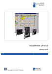
1
User Manual
EM-6335
3.5” SBC with AMD® Embedded G-Series SOC with AMD Radeon™ HD Graphics,
DDR3 up to 8GB, 1 x Intel® Giga LAN, Onboard VGA, 24-bit LVDS, HDMI, audio,
SATA, USB3.0, 4 x COM, 8-bit GPIO, 2 x Mini-PCIe, LPC, DC 8V ~ 32V input
Ver.
Release Date
Update
1.0
2013.08.22
Release
1.1
2013.09.14
Page 37: Correct the LVDS backlight header pin-1 location
Page 40: Correct the LVDS connector pin-1 location
1.2
2013.10.14
AEWIN Technologies Co., Ltd
Update Memory support from 4GB to 8GB
1
EM-6335 User Manual
Copyright
The content of this document and software with this product are copyrighted by
AEWIN technologies Co., Ltd,
This document contains proprietary information protected by copyright. All rights are
reserved; no part of this manual may be reproduced, copied, translated or transmitted
in any form or by any means without prior written permission of the manufacturer.
The content of this document is intended to be accurate and reliable; the original
manufacturer assumes no responsibility for any inaccuracies that may be contained in
this manual. The original manufacturer reserves the right to make improvements to the
products described in this manual at any time without prior notice.
Trademark
All other product names mentioned herein are used for identification purpose only and
may be trademarks and/or registered trademarks of their respective companies.
Limitation of liability
While reasonable efforts have been made to ensure the accuracy of this document,
the manufacturer and distributor assume no liability resulting from errors or omissions
in this document, or from the use of the information contained herein.
For more information or other AEWIN products, please visit our website
http://www.aewin.com.tw.
For technical supports, please send your inquiry to [email protected]
AEWIN Technologies Co., Ltd
2
EM-6335 User Manual
Packing list
Before use this product, please make sure that the following materials have been shipped.
1 x EM-6335 3.5” SBC
1 x CPU cooling Fan
( P/N: 49L-F0056-00 )
1 x SATA cable, L/ 200mm
( P/N: 46L-SATA11-00 )
1 x 12V/5V SATA power cable , L/ 150mm
( P/N: 46L-IPOW41-00 )
1 x COM port, DB9 type, L/ 180mm, without bracket
( P/N: 46L-ICOM34-01 )
1 x dual USB 2.0 cable, L/ 245mm, without bracket
( P/N: 46L-IUSB03-00 )
1 x CD Utility
49L-F0056-00
46L-SATA11-00
46L-IPOW41-00
46L-ICOM34-01
46L-IUSB03-00
Model Name
Description
EM-6335A-D10
AMD® Embedded GX-210HA SOC (D/C 1.0 GHz), HDMI, VGA, LVDS,
GLAN, COM, USB, SATA, Mini-PCIe, DC 8V ~ 32V input
EM-6335A-D16
AMD® Embedded GX-217GA SOC (D/C 1.6 GHz), HDMI, VGA, LVDS,
GLAN, COM, USB, SATA, Mini-PCIe, DC 8V ~ 32V input
EM-6335A-Q15
AMD® Embedded GX-415GA SOC (Q/C 1.5 GHz), HDMI, VGA, LVDS,
GLAN, COM, USB, SATA, Mini-PCIe, DC 8V ~ 32V input
EM-6335A-Q20
AMD® Embedded GX-420CA SOC (Q/C 2.0 GHz), HDMI, VGA, LVDS,
GLAN, COM, USB, SATA, Mini-PCIe, DC 8V ~ 32V input
* If any of those items are missing or damaged, please contact with sales representative or distributor.
AEWIN Technologies Co., Ltd
3
EM-6335 User Manual
Optional Accessory
Photo
Model Name
P/N:
46L-ICOM34-01
Single COM port, DB9 type, L/ 180mm, without bracket
P/N:
46L-IUSB03-00
Dual USB cable, L/ 245mm, without bracket
P/N:
46L-IAUD15-01
Line-out , Line-In , Mic-In audio cable, L/ 180mm, without
bracket
AEWIN Technologies Co., Ltd
4
EM-6335 User Manual
Safety Information
To prevent electrical shock hazard, disconnect the power cable from the electrical
outlet before relocating the system.
When adding or removing devices to or from the system, ensure that the power
cables for the devices are unplugged before the signal cables are connected. If
possible, disconnect all power cables from the existing system before you add a
device.
Before connecting or removing signal cables from the motherboard, ensure that all
power cables are unplugged.
Seek professional assistance before using an adapter or extension cord. These
devices could interrupt the grounding circuit.
Make sure that your power supply is set to the correct voltage in your area.
If you are not sure about the voltage of the electrical outlet you are using, contact
your local power company.
If the power supply is broken, do not try to fix it by yourself. Contact a qualified
service technician or your retailer.
Operation Safety
Before installing the motherboard and adding devices on it, carefully read all the
manuals that came with the package.
Before using the product, make sure all cables are correctly connected and the
power cables are not damaged. If you detect any damage, contact your dealer
immediately.
To avoid short circuits, keep paper clips, screws, and staples away from connectors,
slots, sockets and circuitry.
Avoid dust, humidity, and temperature extremes. Do not place the product in any
area where it may become wet.
Place the product on a stable surface.
If you encounter technical problems with the product, contact a qualified service
technician or your retailer.
AEWIN Technologies Co., Ltd
5
EM-6335 User Manual
Contents
Chapter
Chapter
1
General Information ……………………………………….8
1.1
Introduction …………………………………………..……………………...8
1.2
Specification …………………………………………………..………..…...9
1.3
Block Diagram …………………………………………….…….….............11
1.4
Board layout Dimension ……………………………………….……………..12
1.5
IO / Connector ………………………………………………………………….14
2
Hardware installation …………………………………….16
2.1
The location of onboard connectors ..………………..………………….16
2.2
The location of onboard jumpers ………………………………………...18
2.3
The function list of onboard jumpers setting ……………………………19
2.3.1
JP1 for Power AT/ATX mode select……………………………….…...19
2.3.2
JP2 for Memory module voltage select……………………………..……20
2.3.3
JP3 for Clear CMOS…………………….……………………………..……21
2.3.4
JP4 for LVDS Panel backlight control mode select …….………..……22
2.3.5
JP5 for LVDS Panel power level select…….………………………..……23
2.4
The pin define of onboard pin header ………………………….……......24
2.4.1
CN1 for 3-pin Fan connector………………… ……………..…...........24
2.4.2
CN2 for Full-size Mini-PCIe socket.……………………………..….......25
2.4.3
CN3 for SATA and SATA power connector ………………………........26
2.4.4
CN5 for SIM card socket ........………………………........……………..27
2.4.5
CN6 & 7 for internal USB2.0 pin header .………………………………28
2.4.6
CN8 for SMbus pin header …………………….................................. 29
2.4.7
CN9 for Low Pn Count pin header ..........................................................30
2.4.8
CN10 for GPIO header .......................................................................31
2.4.9
CN11 for WLAN LED indictor of Half-size Mini-PCIe socket ................. 32
2.4.10
CN13 for WLAN LED indictor of Full-size Mini-PCIe socket...................33
2.4.11
CN14 for internal COM2 pin header…………......................................... 34
2.4.12
CN15 for LVDS Panel backlight adjustment ...........................................36
2.4.13
CN16 for LVDS Panel inverter power connector .................................... 37
2.4.14
CN17 for internal COM3 pin header….....................................................38
AEWIN Technologies Co., Ltd
6
EM-6335 User Manual
2.4.15
CN18 for 24-bit Dual Channel LVDS onnector .........................................39
2.4.16
CN19 for internal Audio pin header ...........................................................41
2.4.17
CN20 for front panel pin header ................................................................42
2.4.18
CN21 for internal COM1 pin header……………........................................43
2.4.19
CN25 for internal COM3 pin header..........................................................44
2.4.20
CN30 for Half-size Mini-PCIe socket.........................................................45
2.4.21
CN31 for battery connector........................................................................47
Chapter
3
BIOS Menu Setting
Chapter
4
Programming WDT & GPIO ……………………….........72
Chapter
........………………….............48
4.1
GPIO DOS sample code ............……………………..……………....…..…72
4.2
WatchDog timer DOS sample code .…………………… ..………..…..…...79
5
AEWIN Technologies Co., Ltd
Device Resources
7
........………………...........…..83
EM-6335 User Manual
1.1 Introduction
EM-6335 is a 3.5” SBC with onboard AMD® Embedded G-Series SOC with AMD Radeon™ HD
Graphics. Integrated graphics for three display options include HDMI, VGA and 24-bit dual-channel
LVDS. One DDR3 SO-DIMM supports a maximum of 8GB DDR3 1600 of system memory.
There’re two flexible Mini-PCIe sockets for expansion, one is Full-size type and the other one is
half-size type. Both of them are support standard Mini-PCIe card for PCIe & USB signal-base, such as
WIFI. Besides that, A SIM card holder that could install SIM card when install a Full-size Mini-PCIe 3G
module for wireless connection. For the Half-size Mini-PCIe socket, it’s also support mSATA SSD as
storage device.
Regarding I/O ports , EM-6335 provides plenty of connectivity , such as 1 x Intel® gigabit Ethernet
provided by Intel® i211AT controller, 1 x RS232/422/485 & 3 x RS232, 6 x USB, Audio, 1 x SATA 6Gb/s,
1 x LPC pin-header that could support AEWIN’s TPM module if customer need to protect information.
EM-6335 that could accept wide range DC 8V ~ 32V input, a external DC locking power jack or a 4-pin
internal power connector for easier power integration.
EM-6335 is a small form-factor embedded platform equip with AMD® high performance
Radeon™ HD Graphics and also rich IO ports, make EM-6335 suitable for a wide range of
applications in digital signage, POS, kiosks, and factory automation. Fanless design are allowed for
high temperature and dusty environments.
AEWIN offers reliable and solid products which are produced under Management System Standards:
ISO9001-2000 Certificate. The certificate keeps us focused on our quality objectives of management
and environmental production. Its willingness to customize standard products for meet unique customer
needs makes AEWIN different. All ODM projects are welcome. Years of experiences enables AEWIN to
fulfill the customer’s vision, by delivering products to exact specifications. AEWIN R&D team is proud of
its strong engineering background. R&D professionals account for 25% of the AEWIN workforce. We
focus on developing new products for both emerging and established markets.
For more information about OEM/ODM, please contact us :
Email: [email protected]
AEWIN Technologies Co., Ltd
TEL: +886-2-8692-6677
8
EM-6335 User Manual
1.2 Specification of board
System
From Factor
3.5" SBC
CPU
AMD Embedded GX-210HA SOC with AMD Radeon™ HD 8210E Graphics ( EM-6335A-D10 )
AMD Embedded GX-217GA SOC with AMD Radeon™ HD 8280E Graphics ( EM-6335A-D16 )
AMD Embedded GX-415GA SOC with AMD Radeon™ HD 8330E Graphics ( EM-6335A-Q15 )
AMD Embedded GX-420CA SOC with AMD Radeon™ HD 8400E Graphics ( EM-6335A-Q20 )
Chipset
Integrated
Memory
1 x DDR3 SO-DIMM / 1600 MHz up to 8GB, without ECC support
BIOS
AMI SPI BIOS
SSD
1 x Half-size Mini-PCIe socket support mSATA
Watchdog timer 255 levels, 1 ~ 255 sec
Expansion
1 x Full-size Mini-PCIe socket w/SIM slot. With PCIe X1 & USB signal
1 x Half-size Mini-PCIe socket. With PCIe X1 / SATA signal & USB single
Board Size
146mm x 101mm
Operating Temp. 0°C~60°C (32°F~140°F)
Storage Temp.
.-20°C~80°C (-4°F~176°F)
Operating Hum. 10%~90% (non-condensing)
Display
Chipset
AMD Embedded G-series SOC integrated
Display interface 1 x external VGA
1 x external HDMI 1.4a w/ lockable connector
1 x internal 18/24-bit Dual Channel LVDS
I/O
Series Port
Internal : 1 x RS232/422/485 ( COM2 ), 3 x RS232 ( COM 1/3/4 )
SATA
1 x SATAIII-600MB/s
USB
External : 2 x USB3.0 ( compatible with USB 2.0 )
Internal : 4 x USB2.0
Ethernet
External : 1 x Intel I211AT Gigabit Ethernet
Audio
External : 1 x Line-out
Internal : Line-in/out , Mic-in
Digital I/O
8-bit GPIO interface
LPC
1 x LPC header for Optional TPM module
AEWIN Technologies Co., Ltd
9
EM-6335 User Manual
Others
1 x 3-pin PWM Fan header
1 x Front Panel header for power on/off, reset, HDD/power LED indicator
1 x 2-pin header for battery, 1 x 4-pin 12V/5V DC out for SATA HDD
1 x LVDS Backlight/inverter pin-header, LVDS voltage select.
2 x 2-pin for Full-size/Half-size Mini-PCIe LED indicator header
Power
Power in
DC 8V ~ 32V input ( AT/ATX mode jumper selectable )
Power connector 1 x external DC Jack connector with lockable ( Optional for P4 4-pin internal header )
Note : All specifications and photos are subject to change without notice.
AEWIN Technologies Co., Ltd
10
EM-6335 User Manual
1.3 Block Diagram
1 x DDR3 1600 MHZ
DC 8V ~ 32V input
SO-DIMM0, w/o ECC
( AT/ATX mode )
1 channel
1 x Intel i211AT
DP0
PCIe
CH7511B
2.0G / QC , 25W
Full-Size Mini-PCIe socket
PCIe
w/ SIM holder
24-bit Dual-ch LVDS
1.5G / QC , 15W
1.6G / DC , 15W
1.0G / DC , 9W
4 x Internal USB 2.0
Half-size
USB2.0
Switch
DP1
HDMI 1.4a
VGA
1 x DB15 VGA
PCIe
Mini-PCIe
SATA0
1 x SATAIII
SATA1
LPC header
2 x External USB 3.0/2.0
USB3.0
3 x RS232
SPI
F81866A
F81438
BIOS
1 x RS232/422/485
HDA
Audio
8-bit GPIO
WDT, H/W Monitor
AEWIN Technologies Co., Ltd
11
EM-6335 User Manual
1.4 Board Layout Dimension
AEWIN Technologies Co., Ltd
12
EM-6335 User Manual
AEWIN Technologies Co., Ltd
13
EM-6335 User Manual
1.5 IO ports
HDMI
DC Jack input
24-bit LVDS
VGA
Line-out
USB3.0 GLAN
Front Panel
LVDS inverter
4 x COM
LVDS backlight
Audio pin header
GPIO
Low Pin Count
WLAN LED
SMbus
4 x USB2.0
SATA power
Fan connector
DDR3 SO-DIMM
Mini-PCIe
SATA
SIM socket
AMD® Embedded
G-series SOC
Mini-PCIe
AEWIN Technologies Co., Ltd
14
EM-6335 User Manual
Gigabit Ethernet
Line-Out
AEWIN Technologies Co., Ltd
VGA
Dual USB3.0
DC input with Lockable
HDMI with lockable
15
EM-6335 User Manual
2.1 The location of onboard connectors
CN28
CN29
CN26
CN18
CN22
CN19
CN27
CN24
CN20
CN25
CN23
CN21
CN16
CN17
CN15
CN14
CN13
CN10
CN11
CN9
CN6
CN7
CN4
CN1
SO-DIMM
CN8
CN2
CN5
CN3
CN30
AEWIN Technologies Co., Ltd
16
EM-6335 User Manual
Label
Function
Label
Function
CN1
3-pin Fan connector
CN17
COM4 / RS232 Pin header
CN2
Full-size Mini-PCIe socket
CN18
24-bit LVDS connector
CN3
SATA connector
CN19
Audio pin header
CN4
SATA power connector
CN20
Front panel Pin header
CN5
SIM card socket
CN21
COM1 / RS232 Pin header
CN6
USB2.0 port 4/5 pin header
CN22
Dual USB3.0 connector
CN7
USB2.0 port 2/3 pin header
CN23
P4 4-pin power connector ( Optional )
CN8
5-pin SMbus pin header
CN24
RJ45 LAN connector
CN9
Low Pin Count pin header
CN25
COM3 / RS232 Pin header
CN10
GPIO pin header
CN26
HDMI connector
CN11
WLAN LED connector for Half-size
CN27
Line-out connector
CN12
N/A
CN28
VGA connector
CN13
WLAN LED connector for Full-size
CN29
DC Jack power input connector
CN14
COM2 / RS232/422/485 Pin header
CN30
Half-size Mini-PCIe socket
CN15
LVDS backlight adjustment connector
CN31
Battery connector
CN16
LVDS inverter connector
N/A
AEWIN Technologies Co., Ltd
17
EM-6335 User Manual
2.2 The location of onboard jumpers
JP5
JP4
JP3
JP1
JP5
JP2
Label
JP1
Function
AT/ATX mode select
( 1-2 short : *AT mode , 2-3 short : ATX mode )
JP2
DDR3 Voltage Select
( 1-2 short : *1.5V , 2-3 short : 1.35V )
JP3
Clear CMOS
( 1-2 short : *Normal , 2-3 short : Clear CMOS )
JP4
LVDS Panel backlight control mode select
( 1-2 short : PWM mode , *2-3 short : DC mode )
JP5
LVDS Panel power level select
( 1-2 short : *3.3V , 3-4 short : 5V , 5-6 short : 12V )
* Default setting
AEWIN Technologies Co., Ltd
18
EM-6335 User Manual
2.3 The function list of onboard jumpers setting
- 2.3.1 : JP1 for AT/ATX mode select
JP1 : 1 x 3 header , pitch 2.0 mm
Closed Pin
Result
1-2 *
AT mode
2-3
ATX mode
* Default setting
JP1
3
1
AEWIN Technologies Co., Ltd
19
EM-6335 User Manual
- 2.3.2 : JP2 for DDR3 voltage select
JP2 : 1 x 3 header , pitch 2.0 mm
Closed Pin
Result
1-2 *
Support DDR3 /1.5V memory module
2-3
Support DDR3 /1.35V memory module
* Default setting
JP2
3
AEWIN Technologies Co., Ltd
20
1
EM-6335 User Manual
- 2.3.3 : JP3 for Clear CMOS
If you want to clean the CMOS data, set jumper to 2-3 just for few seconds, Then,
Move the jumper back to 1-2 pin.
JP3 : 1 x 3 header , pitch 2.0 mm
Closed Pin
Result
1-2 *
Normal
2-3
Clear CMOS
* Default setting
3
JP3
1
AEWIN Technologies Co., Ltd
21
EM-6335 User Manual
- 2.3.4 : JP4 for LVDS panel backlight control mode select
JP4 : 1 x 3 header , pitch 2.0 mm
Closed Pin
Result
1-2
PWM mode
2-3 *
DC mode
* Default setting
JP4
1
AEWIN Technologies Co., Ltd
22
3
EM-6335 User Manual
- 2.3.5 : JP5 for LVDS panel power level select
JP5 : 2 x 3 header , pitch 2.0 mm
Closed Pin
Result
1-2 *
+3.3V for LVDS_VCC
3-4
+5V
5-6
+12V for LVDS_VCC
for LVDS_VCC
* Default setting
6
5
2
1
JP5
AEWIN Technologies Co., Ltd
23
EM-6335 User Manual
2.4 The pin define of onboard pin header
- 2.4.1 : CN1 for 3-pin Fan connector
CN1: 1 x 3 wafer
Pin
Signal
Pin
Signal
1
GND
2
+12V
3
Sensor
3
CN1
1
AEWIN Technologies Co., Ltd
24
EM-6335 User Manual
-
2.4.2 : CN2 for Full-size Mini-PCIe socket
Note: Full-size Mini-PCIe only support PCIe + USB signal,
Don’t support SATA signal, such as mSATA SSD …
Pin
Signal
Pin
Signal
1
WAKE
27
GND
2
+3.3V AUX
28
+1.5V
3
N/C
29
GND
4
GND
30
SMBCLK
5
N/C
31
PETN0
6
+1.5V
32
SMBDATA
7
CLKREQ
33
PETP0
8
UIM_PWR
34
GND
9
GND
35
GND
10
UIM_DATA
36
USB_D-
11
REFCLK-
37
GND
12
UIM_CLK
38
USB_D+
13
REFCLK+
39
+3.3V AUX
14
UIM_RESET
40
GND
15
GND
41
+3.3V AUX
16
UIM_VPP
42
LED_WWAN
17
UIM_C8
43
GND
18
GND
44
LED_WLAN
19
UIM_C4
45
N/C
20
W_Disable
46
N/C
21
GND
47
N/C
22
PERST
48
+1.5V
23
PERN0
49
N/C
24
+3.3V AUX
50
GND
25
PERP0
51
N/C
26
GND
52
+3.3V AUX
AEWIN Technologies Co., Ltd
CN2
25
EM-6335 User Manual
-
2.4.3 : CN3 & CN4 for SATA 3.0 connector and SATA power connector
CN3 : SATA 3.0 connector
Pin
Signal
Pin
Signal
1
GND
2
SATA_TX_P0
3
SATA_TX_N0
4
GND
5
SATA_RX_N0
6
SATA_RX_P0
7
GND
CN4 : 4-pin wafer for SATA power connector
Pin
Signal
Pin
Signal
1
+12V
2
GND
3
GND
4
+5V
Note: Maximum output current 12V/1A, 5V/1A.
4
CN4
1
CN3
AEWIN Technologies Co., Ltd
26
1
EM-6335 User Manual
-
2.4.4 : CN5 for SIM card socket
CN5 : SIM card holder
Pin
Signal
Pin
Signal
C1
SIM_PWR
C2
SIM_RESET
C3
SIM_CLK
C4
Reserved
C5
GND
C6
SIM_VPP
C7
SIM_DATA
C8
Reserved
C8
C5
C4
C1
CN5
AEWIN Technologies Co., Ltd
27
EM-6335 User Manual
2.4.5 : CN6 for USB2.0 port pin header
CN6: 2 x 5 header , pitch 2.0 mm
Pin
Signal
Pin
Signal
1
+5V
2
+5V
3
USB D-
4
USB D-
5
USB D+
6
USB D+
7
GND
8
GND
9
Key
10
GND
CN7 for USB2.0 port pin header
CN7: 2 x 5 header , pitch 2.0 mm
Pin
Signal
Pin
Signal
1
+5V
2
+5V
3
USB D-
4
USB D-
5
USB D+
6
USB D+
7
GND
8
GND
9
Key
10
GND
10 9
2
CN7
1
10 9
CN6
2
AEWIN Technologies Co., Ltd
28
1
EM-6335 User Manual
-
2.4.6 : CN8 for SMbus pin header
CN8 : 1 x 5 wafer
Pin
Signal
Pin
Signal
1
+3.3V
2
Clock
3
Data
4
Key
5
GND
5
CN8
1
AEWIN Technologies Co., Ltd
29
EM-6335 User Manual
-
2.4.7 : CN9 for Low Pin Count pin header
CN9 : 2 x 7 header , pitch 2.0 mm
Pin
Signal
Pin
Signal
1
+3.3V
2
LAD0
3
LAD1
4
LAD2
5
LAD3
6
LFRAME_N
7
PLTRST_N
8
+5V
9
LPC_Clock
10
GND
11
GND
12
Key
13
SERIRQ
14
LPC_DREQ
14
13
CN9
2
AEWIN Technologies Co., Ltd
30
1
EM-6335 User Manual
-
2.4.8 : CN10 for GPIO pin header
CN10 : 2 x 6 header , pitch 2.0 mm
Pin
Signal
Pin
Signal
1
+3.3V
2
GPIO0
3
GPIO1
4
GPIO2
5
GPIO3
6
GPIO4
7
GPIO5
8
GPIO6
9
GPIO7
10
Key
11
+5V
12
GND
12
11
2
1
CN10
AEWIN Technologies Co., Ltd
31
EM-6335 User Manual
-
2.4.9 : CN11 for WLAN LED connector for Half-size Mini-PCIe socket
CN11 : 1 x 2 wafer
Pin
Signal
Pin
Signal
1
+3.3V
2
LED-
Note: Support wireless LAN signal only
CN11
2
1
AEWIN Technologies Co., Ltd
32
EM-6335 User Manual
-
2.4.10 : CN13 for WLAN LED connector for Full-size Mini-PCIe socket
CN13 : 1 x 2 wafer
Pin
Signal
Pin
Signal
1
LED-
2
+3.3V
Note: Support WWAN / wireless LAN signal
2
CN13
1
AEWIN Technologies Co., Ltd
33
EM-6335 User Manual
-
2.4.11 : CN14 for COM 2 , RS232/422/485
Note: COM2 RS-232/422/485 can be set by BIOS setting. Default is RS-232.
CN14 : Wafer 1 x 10 header, pitch 1.25 mm, connector type : YIMTEX 501MW1*10STR
Pin
RS232 mode
RS422 mode
RS485 mode
1
DCD, Data carrier detect
TXD-
TXD-
2
DSR, Data set ready
3
RXD, Received Data
TXD+
TXD+
4
RTS, Request to send
5
TXD, Transmitted Data
6
CTS, Clear to sent
7
DTR, Data terminal ready
8
RI, Ring indicator
9
GND
10
N/C
RXD+
RXD-
10
CN14
1
AEWIN Technologies Co., Ltd
34
EM-6335 User Manual
BIOS setting manual :
AEWIN Technologies Co., Ltd
35
EM-6335 User Manual
-
2.4.12 : CN15 for LVDS panel backlight adjustment connector
CN15 : 1 x 4 wafer
Pin
Signal
Pin
Signal
1
LVDS_BLUP
2
GND
3
GND
4
LVDS_BLDN
4
CN15
1
AEWIN Technologies Co., Ltd
36
EM-6335 User Manual
-
2.4.13 : CN16 for LVDS panel inverter power connector
CN16 : 1 x 5 wafer , Pitch : Pitch 2.0 mm
Pin
Signal
Pin
Signal
1
+12V
2
GND
3
Backlight Enable
4
Backlight control
5
+ 5V
1
CN16
5
AEWIN Technologies Co., Ltd
37
EM-6335 User Manual
-
2.4.14 : CN17 for COM 3 , RS232
CN17 : Wafer 1 x 10 header, pitch 1.25 mm, connector type : YIMTEX 501MW1*10STR
Pin
Signal
Pin
Signal
1
DCD, Data carrier detect
2
DSR, Data set ready
3
RXD, Receive data
4
RTS, Request to send
5
TXD, Transmit data
6
CTS, Clear to se
7
DTR, Data terminal ready
8
RI, Ring indicator
9
GND
10
+5V
10
CN17
1
AEWIN Technologies Co., Ltd
38
EM-6335 User Manual
-
2.4.15 : CN18 for LVDS connector
CN18 : connector type : DF13A-40DP-1.25V
Pin
Signal
Pin
Signal
Pin
Signal
1
LVDS_VCC
15
LVDSA_1+
29
GND
2
LVDS_VCC
16
LVDSB_1+
30
GND
3
LVDS_VCC
17
GND
31
DDC_Clock
4
LVDS_VCC
18
GND
32
DDC_Data
5
GND
19
LVDSA_2-
33
GND
6
GND
20
LVDSB_2-
34
GND
7
LVDSA_0-
21
LVDSA_2+
35
LVDSA_3-
8
LVDSB_0-
22
LVDSB_2+
36
LVDSB_3-
9
LVDSA_0+
23
GND
37
LVDSA_3+
10
LVDSB_0+
24
GND
38
LVDSB_3+
11
GND
25
LVDSA_Clock-
39
SMB_Clock
12
GND
26
LVDSB_Clock-
40
SMB_Data
13
LVDSA_1-
27
LVDSA_Clock+
14
LVDSB_1-
28
LVDSB_Clock+
Note: Please select LVDS_VCC for 3.3V/5V/12V by JP5.
1
39
CN18
2
AEWIN Technologies Co., Ltd
40
39
EM-6335 User Manual
BIOS setting for LVDS Resolution:
AEWIN Technologies Co., Ltd
40
EM-6335 User Manual
-
2.4.16 : CN19 for Audio pin header
CN19: 2 x 5 header , Pitch 2.0mm
Pin
Signal
Pin
Signal
1
LINE1-L
2
LINE1-R
3
GND
4
GND
5
MIC1_L
6
MIC1_R
7
key
8
GND
9
FRONT_L
10
FRONT_R
CN19
AEWIN Technologies Co., Ltd
41
9
1
10
2
EM-6335 User Manual
-
2.4.17 : CN20 for front Panel pin header
CN20 : 2 x 4 header , pitch 2.00 mm
Pin
Signal
Pin
Signal
1
Power_LED+
2
Power_LED-
3
HDD_LED+
4
HDD_LED-
5
GND
6
Power on/off
7
Reset
8
GND
8
7
2
1
CN20
AEWIN Technologies Co., Ltd
42
EM-6335 User Manual
-
2.4.18 : CN21 for COM 1 , RS232
CN21 : Wafer 1 x 10 header, pitch 1.25 mm, connector type : YIMTEX 501MW1*10STR
Pin
Signal
Pin
Signal
1
DCD, Data carrier detect
2
DSR, Data set ready
3
RXD, Receive data
4
RTS, Request to send
5
TXD, Transmit data
6
CTS, Clear to se
7
DTR, Data terminal ready
8
RI, Ring indicator
9
GND
10
+5V
10
CN21
1
AEWIN Technologies Co., Ltd
43
EM-6335 User Manual
-
2.4.19 : CN25 for COM 3 , RS232
CN25 : Wafer 1 x 10 header, pitch 1.25 mm, connector type : YIMTEX 501MW1*10STR
Pin
Signal
Pin
Signal
1
DCD, Data carrier detect
2
DSR, Data set ready
3
RXD, Receive data
4
RTS, Request to send
5
TXD, Transmit data
6
CTS, Clear to se
7
DTR, Data terminal ready
8
RI, Ring indicator
9
GND
10
+5V
10
CN25
1
AEWIN Technologies Co., Ltd
44
EM-6335 User Manual
- 2.4.20 : CN30 for half-size Mini-PCIe socket
CN30 : Half-size Mini-PCIe socket
Pin
Signal
Pin
Signal
Pin
Signal
1
MSATA_WAKE
19
N/C
37
N/A
2
+3.3V
20
N/C
38
USB_D+
3
N/C
21
GND
39
V3P3_MSATA
4
GND
22
PLTRST_BUF1_N
40
GND
5
N/C
23
MSATA_RXN4
41
V3P3_MSATA
6
+1.5V
24
MSATA_AUX33
42
LED_WWAN
7
MCLKREQ
25
MSATA_RXP4
43
N/A
8
N/C
26
GND
44
LED_WLAN
9
GND
27
GND
45
N/A
10
N/C
28
+1.5V
46
LED_WPAN
11
MSATA_PE_CLKN
29
GND
47
N/A
12
N/C
30
ICH_SMBCLK
48
+1.5V
13
MSATA_PE_CLKP
31
MSATA_TXN4
49
N/A
14
N/C
32
ICH_SMBDATA
50
GND
15
GND
33
MSATA_TXP4
51
N/A
16
N/C
34
GND
52
+3.3V
17
N/C
35
GND
-
18
N/C
36
USB_D-
-
1
51
2
52
AEWIN Technologies Co., Ltd
CN30
45
EM-6335 User Manual
Note:
Half-size Mini-PCIe card could support USB + SATA or USB + PCIE signal.
The default setting is set as USB + PCIE signal.
Please into BIOS and select SATA or PCIE signal to match your device.
For example :
Please into BIOS and set ” SATA ” when you install a half-size add-on card, such as mSATA SSD.
Please into BIOS and set ” PCIE ” when you install a half-size add-on card, such as WIFI card.
AEWIN Technologies Co., Ltd
46
EM-6335 User Manual
- 2.4.21 : CN31 for Battery connector
CN31 : 1 x 2 header , pitch 2.0 mm
Pin
Signal
Pin
Signal
1
+3V
2
GND
CN31
2
1
AEWIN Technologies Co., Ltd
47
EM-6335 User Manual
3. BIOS setting Menu
- 3.1
Overview
This section explains the BIOS, which displays system configuration settings and allows the changing of
these settings to configure the system. The BIOS Utility consists of a menu-based interface that makes
navigating and selecting various BIOS functions a simple process.
The BIOS Setup Utility can be utilized to view and change BIOS settings for the motherboard. Press <ESC>
key on keyboard during the Power-On Self-Test (POST) routine to enter the Front Page and select the SCU
item to enter the InsydeH2O BIOS Setup Utility.
Use <←> and <→> keys on the keyboard to navigate to each menu. The <↑> and <↓> arrow keys allow
user to navigate to items within each menu. Press <Enter> key to select the item and navigate the item
submenu (if available). Use <ESC> key at any time to return to the previous respective submenu or menu.
You can also refer to the bottom portion of the BIOS Setup Utility screen for quick navigation instructions.
InsydeH20 Setup Utility
Information
Main
Advanced
Security
Menu Name
Information
Power
Boot
Exit
Description
Display BIOS version, Release Date, Kernel, AGENSA version, etc.
Display system information such as CPU type and speed, system bus seed,
Main
system memory speed, total installed memory current language and system
date & time, etc.
Advanced
Allow configuration of advanced system settings such as boot configuration,
ACPI features, and chipset configuration, etc.
Security
Set passwords and security functions.
Power
Configure power management functions.
Boot
Set boot options such as Quick Boot or USB Boot.
Exit
Allow user to save or discard BIOS changes, and load optimal or custom
default settings.
AEWIN Technologies Co., Ltd
48
EM-6335 User Manual
3.2 BIOS Setup Utility
- 3.2.1 Information Menu
The Information Menu of BIOS Setup Utility provide a quick overview of BIOS version and
Reference code version
AEWIN Technologies Co., Ltd
49
EM-6335 User Manual
-
3.2.2 Main Menu
The Main Menu of BIOS Setup Utility provide a quick overview of basic system information and the
ability to change the display language, system time, and copyright description.
AEWIN Technologies Co., Ltd
50
EM-6335 User Manual
-
3.2.3 Advanced Menu
The Advanced Menu of BIOS Setup Utility allows users to configure advanced system settings.
AEWIN Technologies Co., Ltd
51
EM-6335 User Manual
-
3.2.3-1 Advanced Menu
Boot Configuration :
Numlock < Off/On >
Description : Select Power-on state for Numlock. Default setting is <Off>
AEWIN Technologies Co., Ltd
52
EM-6335 User Manual
-
3.2.3-2 Advanced Menu
SB On-chip Devices Configuration:
Mini PCI-E Type Selection
< PCIE/SATA >
Description : Onboard Half-size Mini-PCIe socket support PCIe X1 or STA signal, customer could
select different mode to meet customer’s need. For example :
If select < PCIE >, Half-size Mini-PCIe will support Mini-PCIe module, like WIFI , 3G …
If select < SATA >, Half-size Mini-PCIe will support Mini-PCIe module, like mSATA SSD …
Default setting is <PCIE>
SB On-chip Devices Configuration:
Serial Port B
< RS232/422/485 >
Description : Serial Port B could support RS232/422/485 mode and customer could select here
Default setting is <RS232>
AEWIN Technologies Co., Ltd
53
EM-6335 User Manual
-
3.2.3-3 Advanced Menu
IDE Configuration:
SATA Configure
< AHCI/RAID/IDE >
Description : Select SATA hard disk driver type installed in system
Default setting is <AHCI>
AEWIN Technologies Co., Ltd
54
EM-6335 User Manual
-
3.2.3-4 Advanced Menu
Video Configuration:
UMA Frame buffer Size
< Auto >
Description : Set UMA Frame buffer Size
Default setting is <Auto>
AEWIN Technologies Co., Ltd
55
EM-6335 User Manual
-
3.2.3-4.1 Advanced Menu
Video Configuration:
LVDS Panel Type Selection
< 800x600 18bit >
Description : Select Panel resolution and 18/24-bit channel
Default setting is <800x600 18Bit>
AEWIN Technologies Co., Ltd
56
EM-6335 User Manual
-
3.2.3-4.2 Advanced Menu
Video Configuration:
Boot Display Options
< VGA + HDMI >
Description : Select VGA / HDMI / LVDS display at the same time during the POST
Default setting is <VGA + HDMI>
AEWIN Technologies Co., Ltd
57
EM-6335 User Manual
-
3.2.3-5 Advanced Menu
USB Configuration:
USB2.0
< Enabled/Disabled >
Description : Enable/Disable USB internal 2.0 controller.
Default setting is <Enable>
USB BIOS Support
< Enabled/Disabled >
Description : USB keyboard/mouse/storage support under TEFI and DOS environment.
Default setting is <Enable>
AEWIN Technologies Co., Ltd
58
EM-6335 User Manual
-
3.2.3-6 Advanced Menu
Chipset Configuration:
North Bridge / GNB options
Description : North Bridge / GNB options
AEWIN Technologies Co., Ltd
59
EM-6335 User Manual
-
3.2.3-7 Advanced Menu
CPU Related setting:
CPU P-State Setting
< Auto/lowest Speed>
Description : CPU P-State Setting
AEWIN Technologies Co., Ltd
60
EM-6335 User Manual
-
3.2.3-8 Advanced Menu
Watch Dog Timer:
Watch Dog Timer
Description: Customer could select Time unit here
AEWIN Technologies Co., Ltd
61
EM-6335 User Manual
-
3.2.3-9 Advanced Menu
Console Redirection Setup:
Console Serial Redirect
< Disabled/enabled >
Description: Customer could enabled/disabled Console function here.
Default setting is <Disabled>
AEWIN Technologies Co., Ltd
62
EM-6335 User Manual
-
3.2.3-10 Advanced Menu
Hardware Monitor:
Voltage / Temperature / Fan Speed
Description: Monitor the system Voltage / temperature / Fan speed
AEWIN Technologies Co., Ltd
63
EM-6335 User Manual
-
3.2.3-11 Advanced Menu
Hardware Monitor:
Smart Fan
< Disabled/enabled >
Description: Enabled/Disabled Smart Fan function here.
AEWIN Technologies Co., Ltd
64
EM-6335 User Manual
-
3.2.4 Security Menu
Security Menu of BIOS setup Utility provides configurations for the security settings of the system.
AEWIN Technologies Co., Ltd
65
EM-6335 User Manual
-
3.2.4-1 Security Menu
Select TPM Device:
TPM 1.2 Status
< TPM 1.2 >
Description: If there is no TPM device on platform, TPM status is No Installed,
or it will be enable and active.
Enabled/Disabled TPM function. This option will automatically return to No-operation.
Set Supervisor Password
Description: Install or Change the password and the length of password must be greater than one
character.
AEWIN Technologies Co., Ltd
66
EM-6335 User Manual
-
3.2.5 Power Menu
The power Menu of BIOS Setup Utility allows users to set or control various parameters on CPU
power management, and platform power management.
AEWIN Technologies Co., Ltd
67
EM-6335 User Manual
-
3.2.6 Boot Menu
The boot Menu of BIOS Setup Utility allows users to set bot options.
AEWIN Technologies Co., Ltd
68
EM-6335 User Manual
-
3.2.6-1 Boot Menu
Boot Device Priority:
Normal boot Menu
< Nornal >
Description: Select Normal Boot Option Priority or Advance Boot Option Priority.
AEWIN Technologies Co., Ltd
69
EM-6335 User Manual
-
3.2.6-2 Boot Menu
Boot Device order:
Floopy
Description: Change different devices boot Order.
AEWIN Technologies Co., Ltd
70
EM-6335 User Manual
-
3.2.7 Exit Menu
The Exit Menu of BIOS Setup Utility provides options for user to decide to save changed setting or
not.
AEWIN Technologies Co., Ltd
71
EM-6335 User Manual
4. GPIO and WatchDpg Timer sample code
- 4.1 GPIO Sample Program for DOS environment
//AEWIN GPIO Program for EM-6335(DOS Version)
#include <stdio.h>
#include <string.h>
#include <dos.h>
#include <stdlib.h>
#include <inlines/pc.h>
#define index_port 0x2E
#define data_port 0x2F
void help();
void Enter_SIO();
void Exit_SIO();
int main(int argc, char *argv[])
{
int data_rw8, val;
if (argc!=2){
help();
return;
}
Enter_SIO();
if(strcmp(argv[1], "-80h") == 0){
val = 0x01;
outportb(index_port, 0x89);
data_rw8 = inportb(data_port)&(~val);
data_rw8 |= val;
outportb(data_port, data_rw8);
printf("(Set GP80 to high)\n");
}
else if(strcmp(argv[1], "-80l") == 0){
AEWIN Technologies Co., Ltd
72
EM-6335 User Manual
val = 0x01;
outportb(index_port, 0x89);
data_rw8 = inportb(data_port)&(~val);
outportb(data_port, data_rw8);
printf("(Set GP80 to low)\n");
}
else if(strcmp(argv[1], "-81h") == 0){
val = 0x02;
outportb(index_port, 0x89);
data_rw8 = inportb(data_port)&(~val);
data_rw8 |= val;
outportb(data_port, data_rw8);
printf("(Set GP81 to high)\n");
}
else if(strcmp(argv[1], "-81l") == 0){
val = 0x02;
outportb(index_port, 0x89);
data_rw8 = inportb(data_port)&(~val);
outportb(data_port, data_rw8);
printf("(Set GP81 to low)\n");
}
else if(strcmp(argv[1], "-82h") == 0){
val = 0x04;
outportb(index_port, 0x89);
data_rw8 = inportb(data_port)&(~val);
data_rw8 |= val;
outportb(data_port, data_rw8);
printf("(Set GP82 to high)\n");
}
else if(strcmp(argv[1], "-82l") == 0){
val = 0x04;
outportb(index_port, 0x89);
data_rw8 = inportb(data_port)&(~val);
outportb(data_port, data_rw8);
printf("(Set GP82 to low)\n");
}
else if(strcmp(argv[1], "-83h") == 0){
AEWIN Technologies Co., Ltd
73
EM-6335 User Manual
val = 0x08;
outportb(index_port, 0x89);
data_rw8 = inportb(data_port)&(~val);
data_rw8 |= val;
outportb(data_port, data_rw8);
printf("(Set GP83 to high)\n");
}
else if(strcmp(argv[1], "-83l") == 0){
val = 0x08;
outportb(index_port, 0x89);
data_rw8 = inportb(data_port)&(~val);
outportb(data_port, data_rw8);
printf("(Set GP83 to low)\n");
}
else if(strcmp(argv[1], "-84h") == 0){
val = 0x10;
outportb(index_port, 0x89);
data_rw8 = inportb(data_port)&(~val);
data_rw8 |= val;
outportb(data_port, data_rw8);
printf("(Set GP84 to high)\n");
}
else if(strcmp(argv[1], "-84l") == 0){
val = 0x10;
outportb(index_port, 0x89);
data_rw8 = inportb(data_port)&(~val);
outportb(data_port, data_rw8);
printf("(Set GP84 to low)\n");
}
else if(strcmp(argv[1], "-85h") == 0){
val = 0x20;
outportb(index_port, 0x89);
data_rw8 = inportb(data_port)&(~val);
data_rw8 |= val;
outportb(data_port, data_rw8);
printf("(Set GP85 to high)\n");
}
AEWIN Technologies Co., Ltd
74
EM-6335 User Manual
else if(strcmp(argv[1], "-85l") == 0){
val = 0x20;
outportb(index_port, 0x89);
data_rw8 = inportb(data_port)&(~val);
outportb(data_port, data_rw8);
printf("(Set GP85 to low)\n");
}
else if(strcmp(argv[1], "-86h") == 0){
val = 0x40;
outportb(index_port, 0x89);
data_rw8 = inportb(data_port)&(~val);
data_rw8 |= val;
outportb(data_port, data_rw8);
printf("(Set GP86 to high)\n");
}
else if(strcmp(argv[1], "-86l") == 0){
val = 0x40;
outportb(index_port, 0x89);
data_rw8 = inportb(data_port)&(~val);
outportb(data_port, data_rw8);
printf("(Set GP86 to low)\n");
}
else if(strcmp(argv[1], "-87h") == 0){
val = 0x80;
outportb(index_port, 0x89);
data_rw8 = inportb(data_port)&(~val);
data_rw8 |= val;
outportb(data_port, data_rw8);
printf("(Set GP87 to high)\n");
}
else if(strcmp(argv[1], "-87l") == 0){
val = 0x80;
outportb(index_port, 0x89);
data_rw8 = inportb(data_port)&(~val);
outportb(data_port, data_rw8);
printf("(Set GP87 to low)\n");
}
AEWIN Technologies Co., Ltd
75
EM-6335 User Manual
else if(strcmp(argv[1], "-hhh") == 0){
val = 0xFF;
outportb(index_port, 0x89);
data_rw8 = inportb(data_port);
data_rw8 |= val;
outportb(data_port, data_rw8);
printf("(Set GP80~87 to high)\n");
}
else if(strcmp(argv[1], "-lll") == 0){
val = 0x00;
outportb(index_port, 0x89);
data_rw8 = inportb(data_port);
data_rw8 &= val;
outportb(data_port, data_rw8);
printf("(Set GP80~87 to low)\n");
}
else if(strcmp(argv[1], "-lte") == 0){
val = 0x0F;
outportb(index_port, 0x89);
data_rw8 = inportb(data_port)&0x00;
data_rw8 |= val;
outportb(data_port, data_rw8);
printf("(Set GP80~83 to high, GP84~87 to low)\n");
}
else if(strcmp(argv[1], "-ltd") == 0){
val = 0xF0;
outportb(index_port, 0x89);
data_rw8 = inportb(data_port)&0x00;
data_rw8 |= val;
outportb(data_port, data_rw8);
printf("(Set GP80~83 to low, GP84~87 to high)\n");
}
else if(strcmp(argv[1], "-gpr") == 0){
outportb(index_port, 0x8A);
val = 0x01;
data_rw8 = inportb(data_port)&(val);
AEWIN Technologies Co., Ltd
76
EM-6335 User Manual
if(data_rw8==val)printf("(GP80 is high)\n");
else printf("(GP80 is low)\n");
val = 0x02;
data_rw8 = inportb(data_port)&(val);
if(data_rw8==val)printf("(GP81 is high)\n");
else printf("(GP81 is low)\n");
val = 0x04;
data_rw8 = inportb(data_port)&(val);
if(data_rw8==val)printf("(GP82 is high)\n");
else printf("(GP82 is low)\n");
val = 0x08;
data_rw8 = inportb(data_port)&(val);
if(data_rw8==val)printf("(GP83 is high)\n");
else printf("(GP83 is low)\n");
val = 0x10;
data_rw8 = inportb(data_port)&(val);
if(data_rw8==val)printf("(GP84 is high)\n");
else printf("(GP84 is low)\n");
val = 0x20;
data_rw8 = inportb(data_port)&(val);
if(data_rw8==val)printf("(GP85 is high)\n");
else printf("(GP85 is low)\n");
val = 0x40;
data_rw8 = inportb(data_port)&(val);
if(data_rw8==val)printf("(GP86 is high)\n");
else printf("(GP86 is low)\n");
val = 0x80;
data_rw8 = inportb(data_port)&(val);
if(data_rw8==val)printf("(GP87 is high)\n");
else printf("(GP87 is low)\n");
AEWIN Technologies Co., Ltd
77
EM-6335 User Manual
}
else{
help();
}
Exit_SIO();
return;
}
void Enter_SIO()
{
outportb(index_port, 0x87);
delay(1);
outportb(index_port, 0x87);
outportb(index_port, 0x07);
outportb(data_port,
0x06);
}
void Exit_SIO()
{
outportb(index_port, 0xAA);
}
void help()
{
printf("AEWIN GPIO test program\n");
printf("==============================================\n");
printf("gpio -hhh (Set GP80~87 to high)\n");
printf("gpio -lll (Set GP80~87 to low )\n");
printf("gpio -lte (Set GP80~83 to high, GP84~87 to low)\n");
printf("gpio -ltd (Set GP80~83 to low, GP84~87 to high)\n");
printf("gpio -gpr (Read GPIO status)\n");
printf("gpio -xxh (Set xx to high)\n");
printf("gpio -xxl (Set xx to low)\n");
printf("
(xx=80~87)\n");
printf("==============================================\n");
}
AEWIN Technologies Co., Ltd
78
EM-6335 User Manual
4.2 Watchdog timer Sample Program for DOS environment
//AEWIN Watch dog program for EM-6335(Dos Version)
#include <stdio.h>
#include <string.h>
#include <dos.h>
#include <stdlib.h>
#include <inlines/pc.h>
#define index_port 0x2E
#define data_port 0x2F
//Super IO Index port address
//Super IO Data port address
void Enter_sio_config();
void Exit_sio_config();
void help();
int main(int argc, char *argv[])
{
int data_rw8, time;
if (argc<2){
help();
return;
}
if(strcmp(argv[1], "-s") == 0){
//Show Watchdog Register Settings
Enter_sio_config();
outportb(index_port, 0xF5);
data_rw8 = inportb(data_port)&0x08;
if(data_rw8 == 0x00){
//second mode
outportb(index_port, 0xF6);
data_rw8 = inportb(data_port);
printf("Second mode: %d second\n", data_rw8);
}
AEWIN Technologies Co., Ltd
79
EM-6335 User Manual
else{
//minute mode
outportb(index_port, 0xF6);
data_rw8 = inportb(data_port);
printf("Minute mode: %d minute\n", data_rw8);
}
}
else if(strcmp(argv[1], "-t") ==0 ){
//Set Time-out Value
if(argv[2] == NULL){
help();
return;
}
else{
Enter_sio_config();
outportb(index_port, 0xF6);
outportb(data_port , 0x00);
outportb(index_port, 0xF5);
data_rw8 = 0x32;
//Clear Status
outportb(data_port, data_rw8);
sscanf(argv[2], "%d", &time);
outportb(index_port, 0xF6);
outportb(data_port, time);
if(time==0){
//Disable count
outportb(index_port, 0xF5);
data_rw8 = inportb(data_port)&0xCF;
outportb(data_port , data_rw8);
}
else{
outportb(index_port, 0xFA);
outportb(data_port , 0x01);
//Enable reset function
}
printf("Watchdog Timer will count down for %d second(s)\n", time);
}
}
else if(strcmp(argv[1], "-m") ==0 ){
AEWIN Technologies Co., Ltd
80
EM-6335 User Manual
//Set Time-out Value
if(argv[2] == NULL){
help();
return;
}
else{
Enter_sio_config();
outportb(index_port, 0xF6);
outportb(data_port , 0x00);
outportb(index_port, 0xF5);
data_rw8 = 0x32;
data_rw8 |= 0x08;
//Clear Status
outportb(data_port, data_rw8);
sscanf(argv[2], "%d", &time);
outportb(index_port, 0xF6);
outportb(data_port, time);
if(time==0){
//Disable count
outportb(index_port, 0xF5);
data_rw8 = inportb(data_port)&0xCF;
outportb(data_port , data_rw8);
}
else{
outportb(index_port, 0xFA);
outportb(data_port , 0x01);
//Enable reset function
}
printf("Watchdog Timer will count down for %d minute(s)\n", time);
}
}
Exit_sio_config();
return;
}
void Enter_sio_config()
{
outportb(index_port, 0x87);
delay(1);
AEWIN Technologies Co., Ltd
//Enter W83627EHF Configuration
//Delay some time
81
EM-6335 User Manual
outportb(index_port, 0x87);
outportb(index_port, 0x07);
outportb(data_port , 0x07);
//Super IO Selct Bank Register Number
//Select logical device 7
}
void Exit_sio_config()
{
outportb(index_port, 0xAA);
//Exit W83627EHF Configuration
}
void help()
{
printf("AEWIN Watchdog Timer Program\n");
printf("Usage: WDT -s
(Show Watchdog Register Settings)\n");
printf("Usage: WDT -t xxx (Set Time-out Value)\n");
printf("
xxx = 1 ~ 255 seconds\n");
printf("
xxx = 0 : Time-out Disable \n");
printf("Usage: WDT -m xxx (Set Time-out Value)\n");
printf("
xxx = 1 ~ 255 minutes\n");
printf("
xxx = 0 : Time-out Disable \n");
}
AEWIN Technologies Co., Ltd
82
EM-6335 User Manual
Device Resources
Resource
Share
Device Description
DMA 04
Exclusive
Direct memory access controller
IRQ 00
Exclusive
High precision event timer
IRQ 01
Exclusive
Standard PS/2 Keyboard
IRQ 03
Shared
Communications Port (COM4)
IRQ 04
Shared
Communications Port (COM2)
IRQ 04
Shared
Communications Port (COM3)
IRQ 08
Exclusive
High precision event timer
IRQ 100
Exclusive
Microsoft ACPI-Compliant System
IRQ 101
Exclusive
Microsoft ACPI-Compliant System
IRQ 102
Exclusive
Microsoft ACPI-Compliant System
IRQ 103
Exclusive
Microsoft ACPI-Compliant System
IRQ 104
Exclusive
Microsoft ACPI-Compliant System
IRQ 105
Exclusive
Microsoft ACPI-Compliant System
IRQ 106
Exclusive
Microsoft ACPI-Compliant System
IRQ 107
Exclusive
Microsoft ACPI-Compliant System
IRQ 108
Exclusive
Microsoft ACPI-Compliant System
IRQ 109
Exclusive
Microsoft ACPI-Compliant System
IRQ 110
Exclusive
Microsoft ACPI-Compliant System
IRQ 111
Exclusive
Microsoft ACPI-Compliant System
IRQ 112
Exclusive
Microsoft ACPI-Compliant System
IRQ 113
Exclusive
Microsoft ACPI-Compliant System
IRQ 114
Exclusive
Microsoft ACPI-Compliant System
IRQ 115
Exclusive
Microsoft ACPI-Compliant System
IRQ 116
Exclusive
Microsoft ACPI-Compliant System
IRQ 117
Exclusive
Microsoft ACPI-Compliant System
IRQ 118
Exclusive
Microsoft ACPI-Compliant System
AEWIN Technologies Co., Ltd
83
EM-6335 User Manual
IRQ 119
Exclusive
Microsoft ACPI-Compliant System
IRQ 12
Exclusive
PS/2 Compatible Mouse
IRQ 120
Exclusive
Microsoft ACPI-Compliant System
IRQ 121
Exclusive
Microsoft ACPI-Compliant System
IRQ 122
Exclusive
Microsoft ACPI-Compliant System
IRQ 123
Exclusive
Microsoft ACPI-Compliant System
IRQ 124
Exclusive
Microsoft ACPI-Compliant System
IRQ 125
Exclusive
Microsoft ACPI-Compliant System
IRQ 126
Exclusive
Microsoft ACPI-Compliant System
IRQ 127
Exclusive
Microsoft ACPI-Compliant System
IRQ 128
Exclusive
Microsoft ACPI-Compliant System
IRQ 129
Exclusive
Microsoft ACPI-Compliant System
IRQ 13
Exclusive
Numeric data processor
IRQ 130
Exclusive
Microsoft ACPI-Compliant System
IRQ 131
Exclusive
Microsoft ACPI-Compliant System
IRQ 131071
Exclusive
PCI Express standard Root Port
IRQ 132
Exclusive
Microsoft ACPI-Compliant System
IRQ 133
Exclusive
Microsoft ACPI-Compliant System
IRQ 134
Exclusive
Microsoft ACPI-Compliant System
IRQ 135
Exclusive
Microsoft ACPI-Compliant System
IRQ 136
Exclusive
Microsoft ACPI-Compliant System
IRQ 137
Exclusive
Microsoft ACPI-Compliant System
IRQ 138
Exclusive
Microsoft ACPI-Compliant System
IRQ 139
Exclusive
Microsoft ACPI-Compliant System
IRQ 140
Exclusive
Microsoft ACPI-Compliant System
IRQ 141
Exclusive
Microsoft ACPI-Compliant System
IRQ 142
Exclusive
Microsoft ACPI-Compliant System
IRQ 143
Exclusive
Microsoft ACPI-Compliant System
IRQ 144
Exclusive
Microsoft ACPI-Compliant System
IRQ 145
Exclusive
Microsoft ACPI-Compliant System
IRQ 146
Exclusive
Microsoft ACPI-Compliant System
IRQ 147
Exclusive
Microsoft ACPI-Compliant System
AEWIN Technologies Co., Ltd
84
EM-6335 User Manual
IRQ 148
Exclusive
Microsoft ACPI-Compliant System
IRQ 149
Exclusive
Microsoft ACPI-Compliant System
IRQ 150
Exclusive
Microsoft ACPI-Compliant System
IRQ 151
Exclusive
Microsoft ACPI-Compliant System
IRQ 152
Exclusive
Microsoft ACPI-Compliant System
IRQ 153
Exclusive
Microsoft ACPI-Compliant System
IRQ 154
Exclusive
Microsoft ACPI-Compliant System
IRQ 155
Exclusive
Microsoft ACPI-Compliant System
IRQ 156
Exclusive
Microsoft ACPI-Compliant System
IRQ 157
Exclusive
Microsoft ACPI-Compliant System
IRQ 158
Exclusive
Microsoft ACPI-Compliant System
IRQ 159
Exclusive
Microsoft ACPI-Compliant System
IRQ 16
Shared
High Definition Audio Controller
IRQ 160
Exclusive
Microsoft ACPI-Compliant System
IRQ 161
Exclusive
Microsoft ACPI-Compliant System
IRQ 162
Exclusive
Microsoft ACPI-Compliant System
IRQ 163
Exclusive
Microsoft ACPI-Compliant System
IRQ 164
Exclusive
Microsoft ACPI-Compliant System
IRQ 165
Exclusive
Microsoft ACPI-Compliant System
IRQ 166
Exclusive
Microsoft ACPI-Compliant System
IRQ 167
Exclusive
Microsoft ACPI-Compliant System
IRQ 168
Exclusive
Microsoft ACPI-Compliant System
IRQ 169
Exclusive
Microsoft ACPI-Compliant System
IRQ 17
Shared
Standard Enhanced PCI to USB Host Controller
IRQ 17
Shared
Standard Enhanced PCI to USB Host Controller
IRQ 170
Exclusive
Microsoft ACPI-Compliant System
IRQ 171
Exclusive
Microsoft ACPI-Compliant System
IRQ 172
Exclusive
Microsoft ACPI-Compliant System
IRQ 173
Exclusive
Microsoft ACPI-Compliant System
IRQ 174
Exclusive
Microsoft ACPI-Compliant System
IRQ 175
Exclusive
Microsoft ACPI-Compliant System
IRQ 176
Exclusive
Microsoft ACPI-Compliant System
AEWIN Technologies Co., Ltd
85
EM-6335 User Manual
IRQ 177
Exclusive
Microsoft ACPI-Compliant System
IRQ 178
Exclusive
Microsoft ACPI-Compliant System
IRQ 179
Exclusive
Microsoft ACPI-Compliant System
IRQ 18
Shared
Standard OpenHCD USB Host Controller
IRQ 18
Shared
Standard OpenHCD USB Host Controller
IRQ 180
Exclusive
Microsoft ACPI-Compliant System
IRQ 181
Exclusive
Microsoft ACPI-Compliant System
IRQ 182
Exclusive
Microsoft ACPI-Compliant System
IRQ 183
Exclusive
Microsoft ACPI-Compliant System
IRQ 184
Exclusive
Microsoft ACPI-Compliant System
IRQ 185
Exclusive
Microsoft ACPI-Compliant System
IRQ 186
Exclusive
Microsoft ACPI-Compliant System
IRQ 187
Exclusive
Microsoft ACPI-Compliant System
IRQ 188
Exclusive
Microsoft ACPI-Compliant System
IRQ 189
Exclusive
Microsoft ACPI-Compliant System
IRQ 19
Shared
AMD SATA Controller
IRQ 190
Exclusive
Microsoft ACPI-Compliant System
IRQ 45
Shared
High Definition Audio Controller
IRQ 65536
Exclusive
Intel(R) I211 Gigabit Network Connection
IRQ 65536
Exclusive
Intel(R) I211 Gigabit Network Connection
IRQ 65536
Exclusive
Intel(R) I211 Gigabit Network Connection
IRQ 65536
Exclusive
Intel(R) I211 Gigabit Network Connection
IRQ 65536
Exclusive
Intel(R) I211 Gigabit Network Connection
IRQ 65536
Exclusive
Intel(R) I211 Gigabit Network Connection
IRQ 65536
Exclusive
AMD Radeon HD 8400
IRQ 65536
Exclusive
AMD USB 3.0 Host Controller
IRQ 65536
Exclusive
AMD USB 3.0 Host Controller
IRQ 65536
Exclusive
AMD USB 3.0 Host Controller
IRQ 65536
Exclusive
AMD USB 3.0 Host Controller
IRQ 65536
Exclusive
AMD USB 3.0 Host Controller
IRQ 65536
Exclusive
AMD USB 3.0 Host Controller
IRQ 65536
Exclusive
AMD USB 3.0 Host Controller
AEWIN Technologies Co., Ltd
86
EM-6335 User Manual
IRQ 65536
Exclusive
AMD USB 3.0 Host Controller
IRQ 65539
Shared
Communications Port (COM1)
IRQ 81
Exclusive
Microsoft ACPI-Compliant System
IRQ 82
Exclusive
Microsoft ACPI-Compliant System
IRQ 83
Exclusive
Microsoft ACPI-Compliant System
IRQ 84
Exclusive
Microsoft ACPI-Compliant System
IRQ 85
Exclusive
Microsoft ACPI-Compliant System
IRQ 86
Exclusive
Microsoft ACPI-Compliant System
IRQ 87
Exclusive
Microsoft ACPI-Compliant System
IRQ 88
Exclusive
Microsoft ACPI-Compliant System
IRQ 89
Exclusive
Microsoft ACPI-Compliant System
IRQ 90
Exclusive
Microsoft ACPI-Compliant System
IRQ 91
Exclusive
Microsoft ACPI-Compliant System
IRQ 92
Exclusive
Microsoft ACPI-Compliant System
IRQ 93
Exclusive
Microsoft ACPI-Compliant System
IRQ 94
Exclusive
Microsoft ACPI-Compliant System
IRQ 95
Exclusive
Microsoft ACPI-Compliant System
IRQ 96
Exclusive
Microsoft ACPI-Compliant System
IRQ 97
Exclusive
Microsoft ACPI-Compliant System
IRQ 98
Exclusive
Microsoft ACPI-Compliant System
IRQ 99
Exclusive
Microsoft ACPI-Compliant System
Memory 000A0000-000BFFFF
Shared
AMD Radeon HD 8400
Memory 000A0000-000BFFFF
Shared
PCI bus
Memory 000C0000-000C3FFF
Shared
PCI bus
Memory 000C4000-000C7FFF
Shared
PCI bus
Memory 000C8000-000CBFFF
Shared
PCI bus
Memory 000CC000-000CFFFF
Shared
PCI bus
Memory 000D0000-000D3FFF
Shared
PCI bus
Memory 000D4000-000D7FFF
Shared
PCI bus
Memory 000D8000-000DBFFF
Shared
PCI bus
Memory 000DC000-000DFFFF
Shared
PCI bus
Memory 000E0000-000E3FFF
Shared
PCI bus
AEWIN Technologies Co., Ltd
87
EM-6335 User Manual
Memory 000E0000-000FFFFF
Exclusive
System board
Memory 000E4000-000E7FFF
Shared
PCI bus
Memory 000E8000-000EBFFF
Shared
PCI bus
Memory 000EC000-000EFFFF
Shared
PCI bus
Memory E0000000-EFFFFFFF
Exclusive
AMD Radeon HD 8400
Memory E0000000-F7FFFFFF
Shared
PCI bus
Memory F0000000-F00FFFFF
Exclusive
PCI Express standard Root Port
Memory F0100000-F013FFFF
Exclusive
AMD Radeon HD 8400
Memory F0140000-F0143FFF
Exclusive
High Definition Audio Controller
Memory F0144000-F0147FFF
Exclusive
High Definition Audio Controller
Memory F0148000-F0149FFF
Exclusive
AMD USB 3.0 Host Controller
Memory F014A000-F014A0FF
Exclusive
Standard Enhanced PCI to USB Host Controller
Memory F014B000-F014BFFF
Exclusive
Standard OpenHCD USB Host Controller
Memory F014C000-F014C0FF
Exclusive
Standard Enhanced PCI to USB Host Controller
Memory F014D000-F014DFFF
Exclusive
Standard OpenHCD USB Host Controller
Memory F014E000-F014E3FF
Exclusive
AMD SATA Controller
Memory F0800000-F0FFFFFF
Exclusive
AMD Radeon HD 8400
Memory F1000000-F101FFFF
Exclusive
Intel(R) I211 Gigabit Network Connection
Memory F1000000-F1FFFFFF
Exclusive
PCI Express standard Root Port
Memory F1020000-F1023FFF
Exclusive
Intel(R) I211 Gigabit Network Connection
Memory FC000000-FED3FFFF
Shared
PCI bus
Memory FEC00000-FEC01FFF
Exclusive
Motherboard resources
Memory FED00000-FED003FF
Exclusive
High precision event timer
Memory FED45000-FFFFFFFF
Shared
PCI bus
Memory FEE00000-FEE00FFF
Exclusive
Motherboard resources
Memory FFC00000-FFFFFFFF
Exclusive
System board
AEWIN Technologies Co., Ltd
88
EM-6335 User Manual