1
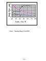
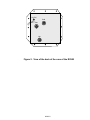
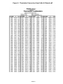
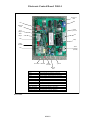
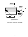
PrecisionTemp RV500 & ShowerMate Water Heater Service Manual For information, contact: PrecisionTemp,Inc. 11 Sunnybrook Dr. Cincinnati, Ohio 45237 Phone: (800)934-9690 Fax: (513)641-0733 www.precisiontemp.com Models: 06/10 RV500 RV501 M500 PrecisionTemp Authorized RV500 Service Schedule The following figures are standard time requirements allowed for repair or replacement of components. Warranty service charges time exceeding these standards will not be paid unless prior approval is obtained from PrecisionTemp. Service charges will be paid in tenths of an hour (six minute increments) General Trouble-Shooting ………… Maximum of 30 minutes (0.5 hour) Repair or replacement of components SM500-01 SM500-02 SM500-03 SM500-04 SM500-06 SM500-07 SM500-08 SM500-09 SM500-10 SM500-11 SM500-12 SM500-13 SM500-14 SM500-15 SM500-16 Hours Circuit board (includes AutoCal) DSI Electrical drawer Hood Heat exchanger assembly T-in T-mid T-out Burner Igniter Flowmeter assembly Gas solenoid Modulating valve (incl. AutoCal) Automatic calibration (AutoCal) Testing the RV500 (1841-RV) (3158) (1435) (1436) (2008) (1437) (1411) (1330) (1073) (1076) 0.3 0.3 0.0 0.0 0.0 0.3 0.3 0.3 0.0 0.0 0.8 0.8 0.9 0.2 0.2 Failure of the RV500 to work properly as a result of improper installation, or conditions caused by non-PrecisionTemp components is not covered by warranty. In the event the estimated warranty time required to service the RV500 would exceed the authorized schedule it is necessary that PrecisionTemp Technical Support be contacted for approval. Without this approval service charges will be paid at the published schedule. 06/2010 CONTENTS Section 1. Definition of Terms Section 2. Description of Operation Section 3. Trouble-Shooting the RV500 3.1 3.2 3.3 3.4 3.5 3.6 3.7 3.8 3.9 3.10 3.11 3.12 Water Leak Gas Leak No Green LED flash or Green LED stays on, but does not flash Green LED flashes, but no ignition attempt (no igniter, no gas) Green LED flashes, but no ignition (igniter sparks, no gas) Green LED flashes, but no ignition (no igniter sparks, no gas flows, no smell) The unit ignites, but will not rise above ignition burn or water at faucet is cool Large fluctuations in temperature During a ‘Navy’ style shower water is cold for a short time after turning off and then back on Pressure relief valve leaks During an automatic calibration procedure (AutoCal) the unit shuts down and restarts Exhaust is smoking Section 4. Water flow system 4.1 4.2 4.3 4.4 Cold water bypass Flowmeter checkout T-in, T-mid, T-out Thermister and T-set readout Using the water system pump Section 5. Service Code Diagnostics Section 6. Repair and Replacement Guide SM500-01 SM500-02 SM500-03 SM500-04 SM500-05 SM500-06 SM500-07 SM500-08 SM500-09 SM500-10 SM500-11 SM500-12 SM500-13 SM500-14 SM500-15 SM500-16 SM500-17 Circuit board DSI Electrical drawer Hood Heat exchanger / burner assembly Heat exchanger assembly T-in T-mid T-out Burner Igniter Flowmeter assembly Gas solenoid Modulating valve Automatic calibration (AutoCal) Testing the RV500 Winter/Cold Weather Protection 06/2010 Section 1. Definition of Terms AutoCal – A procedure by which the microprocessor in the heater accesses a stored calibration table to convert gas flow to voltage to control the gas valve. DSI (Direct Spark Ignition) – The circuit board that controls the ignition process. Once supplied with 12 vdc by the main circuit board, it opens the gas solenoid, sparks the igniter, and senses the flame. Also, during operation it continues to monitor the flame and will fire the igniter if flame rectification is lost. Ignition or minimum burn The ignition gas flow and the lowest burn that the software will permit, which is normally 15,000 – 20,000 Btu. Maximum burn – The highest burn that will pass through the unit, normally 53,000 Btu. T-in – The temperature measured at the entrance to the heat exchanger 1436 T-mid – The temperature measured near the center of the heat exchanger 2008 T-out – The temperature measures at the exit of the heat exchanger 1437 T-set – The stabilization temperature set by the pot on the circuit board 1841-RV 06/2010 Section 2. Description of Operation RV500 With gas and power supplied and no water flow, the RV500 will appear dormant except for the green LED flashing once each second. However, the microprocessor in the RV500 is actively monitoring the three temperature sensors, the set temperature request, and the water flow each half second in anticipation of a request for hot water. When a hot water faucet is opened and flow is 0.5 gpm, the microprocessor sends ignition voltage to the modulating valve and powers the ignition relay on the board which provides 12 vdc to the DSI board. The (Direct Spark Ignition) DSI: Sends 12 vdc to the gas solenoid to open and supply gas to the burner Starts sparking the igniter Monitors the flame presence. When the DSI senses a flame it grounds the feedback to the circuit board. If the flame is not sensed during a 3.5 second ignition attempt the DSI will turn off gas and maintain the feedback signal to the circuit board open (12 vdc) for a 3.0 second purge and repeat the 3.5 second ignition attempt. If there is no flame sensed during the third attempt, the DSI will lockout and feedback will remain open until the software resets it 10 minutes later and the ignition process is repeated. If the flame is lost during normal burn, the DSI will attempt a re-ignition. When the feedback signal is grounded there is flame. Knowing T-in, T-set, and water flow, the software calculates the gas required for the desired set temperature. Stored in a chip on the circuit board is a calibration of the modulating valve (AutoCal). The microprocessor accesses the calibration to convert the gas flow to a voltage to send to the valve. Variations in the heat exchanger and the sensors cause the T-out to be slightly different in reality. To compensate for the variations the microprocessor adjusts the gas flow every 0.5 seconds based on the error between T-out and the T-set. Every 0.5 seconds the microprocessor reads the temperatures and water flow and recalculates the gas flow required. If the water flow changes the gas flow is reset within one second to a new value. Anytime water flow is turned off, the software will turn the gas off within 2 seconds. If you are operating within the capacity of the unit at steady state (see figure-1), you will see small changes in the flame height. These are the small automatic adjustments the software makes to maintain the set temperature. If you operate the RV500 above the capacity, you will see the burner at the maximum burn, however, the outlet water temperature will be below the T-set. Conversely, if you are operating below the capacity then the software cannot lower the burner lower than the minimum burn and the water will heat above T-set. The software will shut off the burner when T-out rises to 16F greater than T-set. It will remain off until T-out < T-set. At the faucet this is seen as fluctuating temperature from very hot to cold. The characteristics above and below the operating range are typical of all instantaneous water heaters. 06/2010 Section 2.1 Description of Operation ShowerMate Note: The next 8 steps take place in 3-5 seconds. The flow meter senses the water flow & sends a flow signal to the green control board. The green control board sends 12 VDC through the orange wire to the pressure differential switch and on to the black relay that powers the power vent blower. The relay closes the 12VDC contacts to start the blower. Fluing is proofed by the vacuum tube that runs from the blower to the pressure differential switch. The pressure differential switch contacts close, sending 12 VDC to the spark ignition module via the orange wire. The Ignition module simultaneously affects a spark through the heavy yellow wire to the spark ignition probe over the burner and sends 12 VDC to the combination gas valve via the blue wire. Ignition of the burner’s element is effected and the flame is proofed and monitored through the same yellow wire by the spark ignition module. The green control board sends DC voltage to the modulating gas valve for one second to effect flame cross-over to all burners. The micro-processor on the green control board monitors water flow with the flow meter and temperature with the three thermistors twice / second and varies voltage 0 – 12 VDC to the gas modulating valve, varying gas flow to burner in order to maintain constant temperature output. Burner remains lit as long as water flow continues, but if flame is extinguished for any reason, the gas valve will shut off in less than 1 second and re-ignition will be attempted. When water is turned off and the water heater no longer senses flow the heater shuts down to standby mode. 06/2010 Section 3. Trouble-Shooting the RV500 3.1 Water Leak Identify the location. If a compression fitting or standard NPT fitting is the source, be sure the fitting is fully tightened. CAUTION: 1) Use two wrenches so that no force is transferred to other parts, and 2) over-tightening fitting can damage the unit. If tightening the compression fitting does not stop the leak, replace the flowmeter and tube assembly. If tightening the compression fitting does not stop the leak, replace the flowmeter and tube assembly. If there is still a leak from a NPT fitting then remove the fitting and try re-taping using plumber’s Teflon tape. Otherwise, replace the component. To replace the leaking part, refer to appropriate location in service manual for change procedure, if necessary. 3.2 Gas Leak Use leak tester to identify the specific location. Correct leak by either: Tightening the fitting Opening the fitting and re-applying thread sealer. The thread sealant must be an AGA-approved product for use with propane gas (LPG). Replacing the leaking parts. CAUTION: When checking for gas leaks DO NOT use flame. 3.3 No Green LED flash or Green LED stays on, but does not flash 1. Be sure power is ON and panel breaker is not tripped. With power OFF detach the ¼ inch spade leads of the power supply (see figure 2). Attach a multi meter and turn power ON. If there is no power then trouble-shoot the coaches electrical system. 2. Be sure all electrical connectors are secure. Check polarity of the 12 vdc supply to the RV500. The positive (+) lead must be connected to the red (+) lead on the rear of the RV500. The negative (-) lead must be connected to the black (-) lead. CAUTION: Supplying the RV500 with reverse polarity will damage the circuit boards. 3. Do you have a converter? If so, the 12 vdc supply to the RV500 must be from the filtered connection on the converter or connected directly to the battery. Refer to your converter manual to verify hookup. Also, check the AC content on the 12 vdc supply to the RV500. Normally, it should be less than 0.3 vac. 4. Open the electrical drawer and check for indications of water or moisture. If you find moisture turn power OFF and let the drawer dry (a hair dryer may be used if you only use warm air). 5. Check the power at the circuit board by placing the multimeter probes on the backside of the 2-pin connector (see figure -4). Voltage should be 10.8 – 14.4 vdc. If voltage is lower than the minimum the ignition board may not function. If voltage is above the maximum it is possible to damage either circuit board. If there is no voltage at the board then the fuse in the power supply cable is blown. Change the power supply cable 1331. 06/2010 6. 7. Examine the micro-controller EL 9049 (see figure -4). Be sure that all pins are in the socket and none appear bent (use thumb to gently press on the chip). If the problem persists then change board 1841-RV. Refer to SM500-01 for the change procedure. 3.4 Green LED flashes, but no ignition attempt (no igniter, no gas) 1. Is the water ON and is the flow out of the faucet at least 0.5 gallons per minute (2.5 minutes to fill 1 gallon)? Flow must be greater than 0.5 GPM for the unit to turn on. 2. Check the T-in, T-mid, and T-out thermisters (see section 4.3 ‘T-in, T-mid, T-out Thermister and T-set readout’). 3. Find the RV500 flowmeter (see figure -3) and verify that the black rotor, visible through the transparent cover, is rotating which indicates that there is flow going through the unit. If the flowmeter is not turning or turning slowly so that the rotor spokes are clearly visible there may be cold water leaking into the hot water lines somewhere in the coach. See the description under the problem Section 4.1 ‘Cold Water Bypass’ to learn more about this condition. If the last letter on your micro-controller 9049 is ‘D’ or later, the flow through the RV500 can be read from the green LED as specified in section 4.3 ‘ Reading flow using the green LED’. Place a finger on the ignition relay on the circuit board (see figure -4) and turn on water. Do you feel or hear a click of the relay actuating? If NO, inspect the micro-controller EL 9049 to confirm that it is pushed in fully and that no pins appear bent or out of the socket If the micro-controller is okay then replace the circuit board 1841-RV per SM500-01. 4. 5. 6. If YES, check that 12 vdc goes to the DSI board 3158 (see figure -4) at the left white wire. If YES, check that the green (ground) wire on DSI cable 1829 is attached under the rightside screw at the burner bracket (see figure -3). If green ground wire is attached then replace the DSI 3158 per SM500-02. If NO, replace the DSI cable 1829. 3.5 Green LED flashes, but no ignition (igniter sparks, no gas) 1. Check the ECO for an open circuit by checking continuity on each connector. On older models check the pop-out button on the ECO 1293 and push in; newer models have auto reset (no button). The ECO is a bi-metal switch that opens when temperature goes above 165F. 2. (see figure -3) 3. Check that the propane tank is ON and there is gas in the tank. Gas pressure to the RV500 while running should be 11.0–14.0 wci. Gas pressure may be too low due to improper gas line diameter (under ¼” diameter) or the gas line being too long (over 25 feet) or ON/OFF solenoid at tank, if you have a solenoid, may have an orifice that is too small (under 3/16” diameter). 4. Check that all four spade connectors are secure to the gas solenoid 1073 (see figure -3). Check that 12 vdc is getting to the gas solenoid 1073 (see figure -3). Removing the top and/or bottom spade connections at the gas solenoid and measuring voltage between the blue and white leads. If there is no voltage or the voltage is less than 10.0 vdc, replace the DSI cable 1829. 5. Use a wrench or similar tool to tap on the gas supply pipe to the right of the coil on the modulating valve 1076 (see figure -3). It is possible that the piston in the modulating valve has been forced out of its normal range and may stick. The tapping helps to free the valve 06/2010 6. Replace the gas solenoid 1073 per SM500-13. 7. Replace the modulating valve 1076 per SM500-14. 3.6 Green LED flashes, but no ignition (no igniter sparks, no gas flow, no gas odor) 1. Check that the ignition wire 1412 is connected to the igniter and then check the wire for continuity. 2. With gas OFF, check if the igniter is sparking to the burner (see figure -3). If not, find where the igniter is sparking. The likely places would be from the bottom of the igniter to the burner bracket and at the right side of the electrical drawer where the ignition wire can be forced against the case. If the spark is at the electrical drawer side then re-route the ignition wire. If the spark is going to the burner bracket, paint the burner bracket in that area with anti-rust paint, or else, cut away the burner bracket so there is about 0.5 inch clearance with the igniter wire. 3. Check that the green (ground) wire on DSI cable 1333 is attached under the right-side screw at the burner bracket (see figure -3). 4. Check the height of igniter electrode above the burner. This height should be 0.125 inch (see figure -8). 5. Disconnect the ignition wire from the DSI spade connector in the electrical drawer (see figure -4). During ignition a spark should be seen at the DSI spade connector. If there is none, replace the DSI board 3158 per SM500-02. If there is a spark, replace the ignition wire 1412 and, find where the spark is occurring along the ignition wire. 3.7 The unit ignites, but will not rise above minimum burn or water at the faucet is cool 1. Check flow out of faucet by measuring the time it takes to fill a gallon container. Calculate water flow in gallons per minute (GPM) by dividing the number one by the time in minutes it takes to collect one gallon of water. Refer to figure -1 to be sure that you are in the normal operating range. 2. If the last letter on your micro-controller EL 9049 is ‘D’ or later then the flow through the RV500 can be read from the green LED as specified in section 4.3 ‘Reading flow using the green LED’. If the flow at the faucet is more than 0.25 GPM greater than the flow through the RV500, read about ‘Cold Water Bypass’. 3. Check the voltage to the modulating valve 1076 by placing multimeter probes in the 2-pin connector (white and black wires) at the circuit board 1841-RV (see figure -4). If the voltage is greater than 2.0 vdc, the modulating valve likely has been forced out of normal range and needs to be returned. 4. While powered, tap on the gas pipe between the gas solenoid and the modulating valve. If this does not free the valve, try using a magnet, starting at the brass fitting on the right side of the coil lay the magnet on the pipe and move from right to left stopping at the wire coil and pulling straight off, or try running AutoCal. (See SM 500-15). (Call for tech assistance 800934-9690). 5. Replace the modulating valve 6. If the voltage is less than 2.0 vdc: 06/2010 7. The RV500 will not increase the flame above minimum until a flameproof signal is sent to the circuit board by grounding the red lead attached to the spade connector on the DSI board. You can do this manually by touching the metal portion of the red wire to the RV500 steel case. The flame should increase. 8. Check thermisters per the section 4.5 ‘T-in, T-mid, T-out Thermister and T-set Readout’. 9. Check DSI harness 1829 red wire for continuity between the circuit board and the DSI spade connector (see figure -4). 10. Change the circuit board 1841-RV. (SM500-01). 11. Check the heater for airflow obstruction and clean. 3.8 Large fluctuations in temperature 1. Are you operating on the water pump? If yes, check if the flowmeter (or water flow) is pulsing at a low flow. If YES, then you may need an accumulator. See the section 4.4 ‘Using the water system pump’. 2. Are the inlet and outlet water supply lines hooked up properly? Check that all screen strainers and filters are clean and not obstructing water flow. The water inlet connection is the upper and the water outlet is the lower. This is the opposite of hot water tanks. You can also check the direction that the flowmeter rotor is turning. It should turn counter-clockwise. 3. There is a built in check/pressure reducing valve in most newer coaches. It is built into the hose hookup assembly. To locate it remove the water supply hose and the strainer/washer. Now, look into the water inlet. You typically will see a plastic spring retainer. By putting a small screwdriver beside the spring retainer and turning it you can increase or decrease water flow. By turning adjust this check valve so that your showerhead, on full hot and no cold water running, makes the green LED on the water heater blink 12 to 16 times between interrupts during the summer and 8 to 12 blinks during winter operation or when on cold well water. When moving from campground to campground you may need to readjust the pressure if you experience hot and cold cycles. This would be due to drastic changes in supply water temperature from campground to campground. Do not make the above water pressure adjustments unless the showerhead flowrestricter has been removed! To remove the showerhead flow-restricter, take the shower hose off the showerhead. Look into the water inlet of the showerhead. You will see a white or gray plastic part with a small hole in it. Turn a screw in to the hole and pull out the small plastic part with a pair of pliers. 4. Is the flame cycling between minimum burn and off? If yes, check the water flow through the unit as described in section 4.3 ‘Reading flow using the green LED’. Then refer to figure -1 to verify that the water flow is above the minimum normal operating line. You can do this step only if the last letter on the micro-controller chip EL 9049 is version ‘D’ or later. 06/2010 5. Is unit changing between min burn and max burn? If yes, run AutoCal per SM500-15. 3.9 During a ‘Navy’ style shower water is cold for a short time after turning off and then back on 1. When water flow is turned off the RV500 will also turn off. Turning the water on again will result in a few seconds of over-heated water and then a few seconds of cold water. Our software minimizes the duration of the cold water, but it takes about three seconds to sense the flow and ignite the burner. The user can do the following: If you are not dry-camping enjoy your shower and let the water run. The RV500 is designed to provide unlimited hot water. The micro-controller should be EL 9049-E or later. 3.10 Pressure relief valve leaks 1. Check water supply pressure 2. Briefly, open valve to clear any debris that might be lodged in the seat. 3. If the valve continues to leak, replace pressure relief valve 1375. 3.11 During the AutoCal procedure the unit shuts down and restarts Check T-out thermister as there may be a hot shift (typical problem found in production). Refer to the section 4.5 ‘T-in, T-mid, T-out Thermister and T-set readout’. Check flow rate by counting flashes from green light. Must be 0.5 gpm or greater. (refer to 4.3) 3.12 Exhaust contains dark smoke 1. While the heater is operating check the burner manifold for any indication of a gas leak. This is observed as a localized, large flame or a flame located other than above the burner. All burners must have a flame. 2. Check for obstructions in the heat exchanger, vent or air intake. 3. Shutdown the unit and contact a factory representative at (800)934-9690. Section 4. 4.1 Cold water bypass 06/2010 A cold water crossover occurs when the cold water is connected to the hot water line and cold water is allowed to enter the hot water line between the water heater and the point of use (see figure -6). The places to look for this happening are outside wash down boxes or showers, water heater bypass kits, showers with a shutoff on the shower head, washing machines, dishwashers, and in the plumbing to water using appliances (usually in parallel instead of in series). There can also be planned crossover in the shower since the Federal government has mandated that all shower mixing valves have anti-scald provisions built into them. If you turn the shower hot water valve on with the cold water valve off you cannot get 100% hot water from it. The shower-mixing valve is designed to always bleed a little cold water in to the hot even when the cold water is off. With the RV-500 series water heater you may feel hotter water coming from your lavatory sink than the shower. This is normal. 4.2 Flowmeter checkout Find the three-pin connector on the circuit board (see figure -4). Place the ground (-) probe of the multimeter in the back of the connector at the black wire and place the high (+) probe at the red wire. With power ON the multimeter should read 5 vdc. If it does not read properly then replace the flowmeter assembly 1330. Now move the high (+) probe to the middle or white wire of the flowmeter. Turn water flow ON (greater than 0.5 GPM). You should see the multimeter jumping to values between 0 and 5 vdc. If you have a multimeter with frequency measurement go to that scale. The frequency is proportional to flow with 27 hertz 1 GPM. If it does not read properly, replace the flowmeter assembly 1330 per SM500-12. 4.3 Reading flow using the green LED Anytime the RV500 detects flow greater than 0.4 GPM it will flash a code on the green LED that corresponds to water flow. With power ON and water running through the unit watch the green LED. The LED will flash approximately once every second. Watch the green LED to find one longer delay between flashes (1.5 seconds versus 1.0 seconds). Begin counting the green LED flashes until the next longer delay. The flashes correspond to water flow. Each flash is 1/8 GPM so that water flow can be calculated: Water flow in GPM = number of green flashes divided by 8 4.4 Using the water system pump When you see or feel pulsing of the water pressure through the showerhead or faucet you are seeing the movement of the diaphragm in the pump. With a diaphragm pump the water does not move in a steady flow like a rotary pump. The diaphragm moves up, pushing the water in that direction. When the diaphragm moves down a check valve opens and lets water in behind the water that was moved up on the up stroke. This causes a momentary hesitation of the water movement in the water line. Under normal circumstances this is no problem. However, with the RV500 series water heaters this can cause a problem. The RV500 series water heaters use a water flow meter. The water heater should not come on if there is a leak in the hot water system. The flow meter is used so the computer can know when the water flow is four-tenths of a gallon per minute or higher before the water heater will come on. The computer also uses the water flow rate, the set temperature, and the incoming water temperature to calculate the BTU setting of the modulating gas valve. If the water pump system is pulsing, the flow meter will read the GPM on the high side of the pulse. The computer will set the gas valve to that BTU setting on the low side of the pulse it will read a new lower GPM setting and say to itself “they just reduced the water flow. Lower the BTU gas setting quickly”. This condition will keep the RV500 series from controlling the water temperature and cause wide temperature fluctuations. To solve this problem an accumulator or expansion tank needs to be installed after the pump. The accumulator tank must have a rubber bladder in it. If there is no bladder the water will absorb the 06/2010 head of air leaving nothing for the water to compress against, leaving the system as if no accumulator tank had been installed. A good accumulator tank will smooth the pulses and make the diaphragm pump a stream as smooth as if it were on city water. 4.5 T-in, T-mid, T-out Thermister and T-set readout If the red LED is flashing, turn power OFF for 5 seconds and then turn power ON? If the red LED is flashing, there is a potential problem with a thermister. To diagnose the problem, run water though the unit for at least 30 seconds with the power OFF then turn the water off. The output of the thermister should be checked with the power ON using a multimeter. Plug the ground (-) probe into the black test connector (TP1) on the circuit board 1841-RV and the high (+) probe into: T-out T-mid T-in T-set orange test connector (TP2) yellow test connector (TP3) 6 pin connector on 1841-RV at right (inboard) blue wire blue test connector (TP4) Compare the voltage reading of the three thermister outputs which should all be within .5 volts of each other. Turn power OFF. Unplug the 2-pin connectors (figure -4) and, using a multimeter, check the resistance across the each thermister. If the suspect thermister is more than 75 ohms from the other thermisters, replace the thermister. Otherwise, replace the thermister cable (1329) first. If that does not fix the problem, replace the thermister. T-set is set to 2.0 vdc (120F) at the factory. The T-set pot output will change about 0.44 vdc (7F) per turn of the pot. For example, to adjust T-set to 122F turn the pot until the readout is 2.0 vdc. Section 5. Service Code Diagnostics Note: All red LED flashes can be reset by cycling the power OFF for 5 seconds and then ON. Double red flash/second (two flashes per second) Indicates that the T-mid thermister has failed. The heater will not operate without maintenance action. Check that the 2-pin and 6-pin connectors are all plugged in and inspect the wiring for any indications of a problem. Unplug the T-mid thermister 2008 at the 2-pin connector and check the 06/2010 thermister cable 1329 for continuity on the two yellow wires. If either wire shows a break, replace the cable 1329. Otherwise, replace the T-mid thermister 2008 per SM500-08. Single Red flash Indicates that the T-out thermister has failed. The heater will substitute a calculated (model) T-out, based on T-mid, and continue to operate. At a constant water flow the temperature output will remain constant. Over the operating water flow range, normally, this approximation will be within 3F. If the variation is noticeable and improvement is needed, proceed with the checkout in section 4.3 and, if necessary, replace the T-out thermister per SM500-09. Otherwise, the unit can continue to operate. Two Red flashes Indicates that the T-in thermister has failed. The heater will assume 70F for T-in and continue to operate. As long as incoming water temperature is near 70F operation will be normal. However, as inlet water temperature deviates from 70F the unit will be slower reaching the set temperature and eventually, the unit will be unable to reach the set temperature. If the variation is noticeable and improvement is needed, proceed with the checkout in section 4.3 and, if necessary, replace the T-in thermister per SM500-07. Otherwise, the unit can continue to operate. Three Red flashes T-mid is not in the operating range of 30 - 160F. The unit continues to operate using the measured T-mid, however, the operation is likely affected since the T-out model will be much different and the unit will not be able to reach the set temperature at many or all water flows. If the variation is noticeable and improvement is needed then proceed with the checkout in section 4.3 and, if necessary, replace the T-mid thermister per SM500-08. Otherwise, the unit can continue to operate. Four Red flashes T-out is not in the operating range of 30 - 180F. The unit continues to operate using the measured T-out, however, the operation is likely affected since the real heat exchanger outlet temperature will be much different and the unit will not be able to reach the set temperature at many or all water flows. If the variation is noticeable and improvement is needed then proceed with the checkout in section 4.3 and, if necessary, replace the T-out thermister per SM500-09. Otherwise, the unit can continue to operate. Temporary, improved operation may be obtained by disconnecting the T-out thermister at the 2-pin connector (see ‘Single Red Flash’). Five Red flashes T-in is not in the operating range of 30 - 110F. The unit continues to operate using the measured Tin, however, the operation is likely affected since the real heat exchanger inlet temperature will be much different and the unit will not be able to reach the set temperature at many or all water flows. If the variation is noticeable and improvement is needed then proceed with the checkout in section 4.3 and, if necessary, replace the T-in thermister per SM500-07. Otherwise, the unit can continue to operate. Temporary, improved operation may be obtained by disconnecting the T-in thermister at the 2-pin connector (see ‘2 Red Flashes’). Six Red flashes T-in is larger than T-mid and T-mid is larger than T-out. This indicates that the water is flowing through the unit backwards. Check the water inlet and outlet connections because they must be reversed. The water inlet is the upper connection and the water outlet is the lower connection. This is the opposite of RV hot water tanks. Seven Red flashes The direct spark ignition (DSI) has timed out (after two 3.5 second ignition attempts) and the DSI board 3158 has locked out. After 45 seconds the software on circuit board 1841-RV will reset the DSI board and the ignition sequence will be repeated. The DSI can also be reset by turning off water a few seconds and then on. The red LED will continue to flash even though the unit is now operating. The red LED can be reset by cycling the power OFF, then ON. If the unit frequently locks out refer to section 3.6 ‘Green LED flashes, but no ignition (no igniter sparks, no gas flow, no odor). 06/2010 Water Flow - gpm 4 Exceeds Range 3 2 Operating Range 1 Below Range 0 20 30 40 50 60 T-out – T-in, ºF Figure 1. Operating Range of the RV500 06/2010 70 80 12 VDC Cold Gas Hot Figure 2. View of the back of the case of the RV500 06/2010 1434 Burner/Heat Exchanger 2008 2086 1588 1437 1330 1073 1076 1375 Front View 1315 1076 2008 1315 1434 1436 1437 2086 1330 1375 1073 1436 Modulating Gas Valve, LPG Heat Exchanger Core Temperature Sensor Burner Assembly Burner/Heat Exchanger Assembly Inlet Temperature Sensor Outlet Temperature Sensor ECO Flow Meter Pressure Relief Valve LPG Gas Solenoid Figure 3. Frontal View of RV500 with Door Removed 06/2010 Figure 5. Thermister Conversion from Volts & Ohms to F 06/2010 Electronic Control Board 200-14 Brown Test Point 1076 1331 Black Test Point Micro processor ACAL Jumper JMP 1 Jumper 1333 1330 Relay Orange Test Point Alarm Connector (not used) 1329 Green LED Red LED Yellow Test Point T_set Pot Blue Test Point 1076 1329 1330 1331 1333 Alarm ACAL Jumper JMP 1 Jumper Orange Test Point Yellow Test Point Blue Test Point Brown Test Point Black Test Point Modulating Gas Valve Connection Thermister Wiring Harness Connector Flowmeter Connection Power Supply Wiring Harness Connector DSI Wiring Harness Connector Alarm Connector Not Used (in this application) Jumper for Auto-Cal Board Function Jumper Test Point for T_out Thermister Test Point for T_mid Thermister Test Point for Setting Temperature Test Point for Modulating Valve Test Point for Ground (common) Revision 04/04 06/2010 Normal operation Cold in Water Cold in open open closed closed Hot out Shower head with shut off Cold water crossover Water Cold in open Cold in open open open Hot out Shower head with shut off closed Example of a “cold water crossover” Hot water Cold water Figure 6. Cold Water Bypass T-mid Thermister Pipe Fitting This end into Heat Exchanger Ferrule Yellow Wires Figure 7. T-mid Ferrule Assembly 06/2010 Spark gap to be 0.125 1411 1076 1411 1315 Manifold Pressure Tap 1076 Modulating Gas Valve LPG 1315 Burner Assembly 1411 Igniter Figure 8. Burner Assembly - Gas Train Assembly 06/2010 RV500 Wiring Schematic 2004 & prior years 06/2010 06/2010 Model: RV500-F-L / RV501-F-L Schematic RV500 2004 - present SM500-01 Circuit Control Board Replacement Other service documents required: SM500-15 Automatic calibration (AutoCal) SM500-16 Testing the RV500 Tools Required: Needle-nose pliers 1. Turn off power. Disconnect all electrical connectors at the circuit board. 2. Remove the circuit board. A needle-nose plier can be used to remove the circuit board standoffs. 3. Remove the two black LED holders (if necessary) so they will not interfere with the installation of the new board. 06/2010 4. Install the new board with the LEDs located at the front of the drawer. Reconnect all connectors to the board. CAUTION: there are two two-pin connectors. Be sure that the power supply connector (red and black wire) goes to upper left corner and the valve connector (white and black wire) goes to upper right (see figure -4). 5. Put the LED holders in. 6. The set temperature is already at 122F. Refer to manual if a further adjustment is desired. 7. You must run AutoCal to complete the installation. Refer to SM500-15. 8. Perform a test of the unit. Refer to SM500-16 ‘Testing the RV500’. Kit Parts List: 1841- RV Control Board Figures: Figure-4 Model: View of the Electronic Drawer RV500-F-L / RV501-F-L SM500-02 Direct Spark Ignition (DSI) Board Change Other service documents required: none Tools Required: ¼” socket 5/16”wrench Velcro strips 1. Turn off power. Disconnect all electrical connectors at the DSI board. 06/2010 2. Remove the electronics drawer. To remove the board requires a ¼” socket or a 5/16” wrench. 3. Install the new DSI board and re-attach the wire harnesses. Be sure to route the ignition harness separate from the other control harnesses. Kit Parts List: 3158 3166 Figures: none Model: Direct Spark Ignition (DSI) board DSI Mounting Bracket RV500-F-L / RV501-F-L SM500-03 Electrical Drawer Assembly Change Other service documents required: SM500-16 Testing the RV500 Tools Required: none 1. Turn power OFF. 2. Remove the door and locate the electrical drawer AS 1438 (see figure -3). 06/2010 3. Slide the drawer forward to reveal the two circuit boards AS 1312 and EB 1378. Wire harnesses will not permit the drawer to be removed. Disconnect the one connection to EB 1378 and the five (5) connections to AS 1312. All electrical connectors in the drawer should now be disconnected and the drawer can slide out of the guides. 4. Route the wire harnesses through the grommets of the new drawer. Be sure to route the ignition harness separate from the other control harnesses. Then slide the drawer unto the guides. 5. Re-connect the nine (9) electrical connections. 6. Perform a test of the unit. Refer to SM500-16 ‘Testing the RV500’. Kit Parts List: 1438 Assembly, Electrical Drawer Figures: Figure-3 Frontal view of RV500 without door SM500-04 Hood Change Procedure Other service documents required: None Tools Required: Phillips screwdriver 1. Turn off power. 2. Open the electrical drawer and disconnect the two connectors on the DSI board EB 1378 and the five connectors on the circuit board AS 1312 (refer to figure -4). Route the cables out of the drawer and then slide the electrical drawer out. 06/2010 3. Note: Model 500 with serial numbers prior to 97-07-xxxx. Remove the four sheetmetal screws located two on each side of the case. The head of the screw is accessed from the outside of the case. If the screws are not accessible then the case must be pulled from the RV sufficiently to access the screws. Note: Model 500 with serial numbers after 97-07-xxxx and ALL MODEL 501 Using a Phillips screwdriver remove the 8-32 screw located at the middle rear of the hood (see figure -3). Then remove the two 8-32 screws located at the upper front of the hood. These screws are accessible through holes in the lower hood that have been covered with metal tape. Note: Model 500 with serial numbers starting with 05-XX-XXXX remove the two 8-32 screws located at the upper front of the hood. These screws are accessible through holes in the lower hood that have been covered with metal tape 4. Lift the hood until it clears the heat exchanger and then bring the hood forward to remove it from the case. 5. Slide the electrical drawer into the new hood. 6. Install the new hood reversing steps 4, 3, and 2. Kit Parts List: Hood assembly 1327 Other service documents required: none Tools Required: Phillips screwdriver Figures: Figure-3 Figure-4 Model: Frontal View of RV500 with Door Removed View of Electronic Drawer RV500-F-L / RV501-F-L SM500-05 Heat Exchanger / Burner Assembly Replacement Other service documents required: SM500-16 Testing the RV500 SM500-04 Hood Change Procedure Tools Required: Phillips screwdriver ¼” socket 9mm open end wrench Side cutters 2 adjustable wrenches 06/2010 7/8 open end wrench 4. Turn power OFF, water OFF, and gas OFF. 5. Disconnect the gas line, water inlet, and water outlet. 6. Remove the hood assembly per SM500-04. 7. Remove the two 8-32 screws on the sides of the burner bracket using the ¼” socket and 9mm open end wrench. Refer to figure -3. 8. Slide the heat exchanger / burner assembly 1434 forward and out of the case. 9. Remove the thermister cable 1329 and DSI cable 1829. 10. Assemble the thermister cable 1329 and DSI cable 1829 from step 5 onto the new heat exchanger / burner assembly. 11. Reverse the procedure of steps 4, 3, and 2 to complete assembly. 12. Check the unit for normal operation per SM500-16 ‘Testing the RV500’ Kit Parts List: 1434 Heat exchanger / burner assembly Figures: Figure-3 Figure-4 Model: Frontal View of RV500 with Door Removed View of Electronic Drawer RV500-F-L / RV501-F-L SM500-06 Heat Exchanger Assembly Replacement Other service documents required: SM500-04 Hood Change Procedure SM500-05 Heat Exchanger / Burner Assembly Replacement SM500-16 Testing the RV500 Tools Required: Phillips screwdriver ¼” socket 9mm open end wrench 3/8” socket level 06/2010 13. Turn power OFF, water OFF, and gas OFF. 14. Remove the hood assembly per SM500-04. 15. Remove the heat exchanger / burner assembly 1434 per SM500-05. 16. Remove the two 8-32 machine nuts from the left side of the heat exchanger that attach the heat exchanger assembly 1435 from the burner assembly 1315. 17. Turn the new heat exchanger assembly 1435 upside down and place on a flat, level table. Position the burner assembly 1315 onto the burner so that the high side of the burner is on the outside of the heat exchanger and the other side of the heat exchanger is resting on the ledge of the burner assembly. See figure -8. 18. Be sure the table is level. Place a level on the burner bracket. Adjust the burner assembly until it is level and then mark the heat exchanger through the two mounting holes in the burner bracket. 19. Remove the burner assembly and drill ¼” holes at the two marked holes on the heat exchanger. 20. Again place the burner on the heat exchanger. From the inside of the heat exchanger assemble the heat exchanger backup plate through the two holes of the heat exchanger and burner. Use the two new 8-32 self-locking screws 1397 and a 3/8” socket to tighten the assembly. Recheck that the upside down assembly is still level as determined in step 6. 21. Reverse the procedure of steps 3, and 2 to complete assembly. 22. Check the unit for normal operation per SM500-16 ‘Testing the RV500’ Kit Parts List: 1435 Heat exchanger assembly Figures: Figure-3 Frontal View of RV500 with Door Removed Figure-4 View of Electronic Drawer Figure-8 Burner Assembly Model: RV500-F-L / RV501-F-L SM500-07 T-in Thermister Change Procedure Other service documents required: SM500-16 Testing the RV500 Tools Required: Scissors (or other cutting tool) 06/2010 1. Remove the wire ties, metal tape, and old thermister. Clean off the old heat sink and be sure copper is wiped clean. Note : T-in thermistor position changed on newer models. Current location is on the same tube forward of the PRV where the pipe makes a 90 degree vertical at the copper heat exchanger. 2. Apply heat sink compound to copper tube. 3. Place the thermister into the heat sink compound. Wrap metal tape around the tube and thermister. 4. Take the two wire ties. One goes around the wires as a strain relief. The other goes near the thermister (about 3/8” away from the head) to hold the thermister against the tube. CAUTION: Do not place the tie wrap over the thermister tip as this may crack the thermister, and Do not over-tighten the wire ties. 5. Check the resistance across the thermister leads. Under room temperature conditions the value should be between 700 - 1100 ohms. A further check may be to compare the resistance measurement to the other two thermisters. If all thermisters have been exposed to the same temperature they should be within 50 ohms. 6. Route the blue wire leads over the modulating valve keeping the wires away from the burner. Wrap the harness together and connect into the thermister harness that goes back to the control board. 7. Perform a test of the unit. Refer to SM500-16 ‘Testing the RV500’. Kit Parts List: 1436 Figures: none Model: T-in thermister assembly RV500-F-L / RV501-F-L SM500-08 T-mid Thermister Change Procedure Other service documents required: SM500-16 Testing the RV500 Tools Required: 14 mm open end wrench (or adjustable) 9/16” open end wrench 1. Remove old thermister. CAUTION: Use two wrenches: one on the hex (9/16”) of the thermister and one on the hex (14 mm) located on the heat exchanger fitting. Failure to do so may damage the heat exchanger. 06/2010 2. Place the fitting and the ferrule on the thermister as shown in figure -7. 3. Insert the end of the thermister without electrical leads into the heat exchanger until the heat shrink (black) on the thermister touches the fitting and tighten the fitting finger-tight. Wiggle to locate center. The final tightening should be done using two wrenches as described in step 1. 4. Check the resistance across the thermister leads. Under room temperature conditions the value should be between 700 - 1100 ohms. A further check can be done by comparing this resistance to the other two thermisters. If all thermisters have been exposed to the same temperature they should be within 50 ohms. 5. Wire tie the harness together with the other two thermister harnesses and connect into the thermister harness that goes back to the control board. 6. You must run AutoCal to complete the installation. Refer to SM500-15. 7. Perform a test of the unit. Refer to SM500-16 ‘Testing the RV500’. Kit Parts List: 2008 T-mid thermister assembly Figures: Figure-7 Model: T-mid Ferrule Assembly RV500-F-L / RV501-F-L SM500-09 T-out Thermister Change Procedure Other service documents required: SM500-16 Testing the RV500 Tools Required: Scissors (or other cutting tool) 1. Remove the wire ties, metal tape, and old thermister. Clean off the old heat sink and be sure copper is wiped clean. 2. Place a large dab of heat sink compound on the pipe to replace the compound removed. 3. Place the thermister into the heat sink compound with the wire leads pointing down along the tube. Make sure the tip of the thermister is completely submerged in the compound. 4. Wrap metal tape around the tube and thermister. 06/2010 5. Take the two wire ties. One goes around the wires as a strain relief. The other goes near the thermister (about 3/8” away from the head) to hold the thermister against the tube. CAUTION: 1) Do not place the tie wrap over the thermister tip as this may crack the thermister, and 2) Do not over-tighten the wire ties. 6. Check the resistance across the thermister leads. Under room temperature conditions the value should be between 700 - 1100 ohms. A further check may be to compare the resistance measurement to the other two thermisters. If all thermisters have been exposed to the same temperature they should be within 50 ohms. 7. Wire tie the thermister harnesses together and connect into the thermister harness that goes back to the control board. 8. Perform a test of the unit. Refer to SM500-16 ‘Testing the RV500’. Kit Parts List: 1437 T-out thermister assembly Figures: none Model: RV500-F-L / RV501-F-L SM500-10 Burner Assembly Replacement Other service documents required: SM500-16 Testing the RV500 Tools Required: Phillips screwdriver ¼” socket 9mm open end wrench 3/8” open end wrench level 1. Turn power OFF, water OFF, and gas OFF. 2. Remove the hood assembly per SM500-04. 3. Remove the heat exchanger / burner assembly 1434 per SM500-05. 4. Remove the two 8-32 machine nuts from the left side of the heat exchanger that attach the heat exchanger assembly 1435 from the burner assembly 1315. 5. Turn the heat exchanger assembly 1435 upside down and place on a flat, level table. Assemble the new burner assembly 1315 onto the burner so that the high side of the burner is on the 06/2010 outside of the heat exchanger and the heat exchanger other side is resting on the ledge of the burner assembly. See figure -8. 6. Be sure the table is level. Place a level on the burner bracket. Adjust the burner assembly until it is level and mark the heat exchanger through the two mounting holes in the burner bracket. 7. Remove the burner assembly and drill ¼” holes at the two marked holes on the heat exchanger. 8. Again place the burner on the heat exchanger. From the inside of the heat exchanger assemble the heat exchanger backup plate through the two holes of the heat exchanger and burner. Use the two new 8-32 self-locking screws 1397 and a 3/8” open end wrench to tighten the assembly. Recheck that the upside down assembly is still level as determined in step 6. 9. Reverse the procedure of steps 3, and 2 to complete assembly. 10. Check the unit for normal operation per SM500-16 ‘Testing the RV500’ Kit Parts List: 1315 Burner assembly Figures: Figure-3 Figure-4 Figure-8 Model: Frontal View of RV500 with Door Removed View of Electronic Drawer Heat Exchanger / Burner Assembly Method RV500-F-L / RV501-F-L SM500-11 Igniter Replacement Other service documents required: SM500-04 Hood Change Procedure SM500-05 Heat Exchanger / Burner Assembly Replacement SM500-06 Heat Exchanger Assembly Replacement SM500-10 Burner Assembly Replacement SM500-16 Testing the RV500 Tools Required: Phillips screwdriver ¼” socket 9mm open end wrench 3/8” open end wrench or socket Level Pliers 1/8” drill bit 1. Turn power OFF, water OFF, and gas OFF. 2. Remove the hood assembly per SM500-04. 06/2010 3. Remove the heat exchanger / burner assembly 1434 per SM500-05. 4. Separate the heat exchanger assembly 1435 and burner assembly 1315 per SM500-06 or SM500-10. 5. Remove the one screw 1409 that attaches the igniter bracket 1410 and electrode 1411. 6. Replace the electrode and re-assemble onto the burner. 7. Using the 1/8” drill bit as a gage, bend the end of the electrode with the pliers until it is centered over the burner blade and 1/8” above the burner (see figure -8). 8. Re-assemble the heater reversing the procedure of steps 4, 3, and 2. 9. Check the unit for normal operation per SM500-16 ‘Testing the RV500’ Kit Parts List: 1411 Electrode Figures: Figure-3 Figure-4 Figure-8 Model: Frontal View of RV500 with Door Removed View of Electronic Drawer Burner assembly/Electrode Adjustment RV500-F-L / RV501-F-L SM500-12 Flowmeter Replacement Other service documents required: SM500-16 Testing the RV500 Tools Required: Adjustable wrench 13/16 open end wrench Teflon thread tape 10. Turn power OFF, water OFF, and gas OFF 11. Disconnect the flow meter connector from the control board (J3) and remove connector/wire from drawer. Remove drawer from shelf and let hang. 12. Loosen the upper compression fitting nut (see figure SM500-3). Carefully turn the flowmeter counter clockwise to release the bottom connection. 13. Reverse the above procedure and install the new flowmeter assembly, use Teflon pipe thread tape to seal the threaded connections. 06/2010 14. You must run AutoCal to complete the installation. Refer to SM500-15. 15. Check the unit for normal operation per SM500-16 ‘Testing the RV500’ Kit Parts List: 1330 Flowmeter assembly Figures: Figure-3 Figure-4 Model: Frontal View of RV500 with Door Removed View of Electronic Drawer RV500-F-L / RV501-F-L SM500-13 Gas Solenoid Replacement Other service documents required: SM500-16 Testing the RV500 Tools Required: Basin wrench or crow foot wrench Adjustable wrench 1. Turn power OFF, water OFF, and gas OFF. 2. Disconnect the gas supply. 3. Disconnect the four spade connectors at the gas solenoid. 4. Place an adjustable wrench on the modulating valve hex and unscrew the gas solenoid 1073 from the end of the piping and remove from the unit. 5. Remove the flare elbow from the gas solenoid. 06/2010 6. USE AGA-APPROVED SEALANT ON ALL GAS THREAD CONNECTIONS. Assemble the flare elbow into the new gas solenoid. 7. Screw the gas solenoid 1073 onto the end of the piping in the case. Continue to tighten until the spade connections are to the rear of the unit. 8. Attach the four spade connections. Looking from the front, the two blue wires attach on the left and the two white wires on the right. 9. Connect the gas supply and test for leaks. 10. Check the unit for normal operation per SM500-16 ‘Testing the RV500’. Kit Parts List: 1073 Gas Solenoid Figures: Figure-3 Model: Frontal View of RV500 with Door Removed RV500-F-L / RV501-F-L SM500-14 Modulating Valve & Coil Replacement Other service documents required: SM500-15 Automatic Calibration (AutoCal) SM500-16 Testing the RV500 Tools Required: Basin wrench or slip/channel pliers 2 Adjustable wrenches or 9mm open end wrench 7/8 wrench 1. Turn power OFF, water OFF, and gas OFF. 2. Unplug the Modulating valve connector from the control board (J4). 3. Disconnect the gas line from the gas solenoid and unplug wire connectors from gas solenoid. 4. Place an adjustable wrench on the modulating valve hex and unscrew the gas solenoid and piping from the end of the modulating valve. 06/2010 5. Use the 7/8 wrench on the modulating valve hex to unscrew the valve and pipe nipple from the burner manifold. Then separate the pipe nipple from the valve. 6. To replace the coil only remove the C clip from the modulating valve tube, slide the coil off and install replacement coil. Make sure the direction arrow is pointed toward the manifold. Reinstall C clip. 7. USE AGA-APPROVED SEALANT ON ALL GAS THREAD CONNECTIONS. Assemble the pipe unto the new modulating valve and into the manifold. Take care not to get any thread sealant into the modulating valve because this will cause the valve to stick. 8. Re-assemble the heater reversing the procedure of steps 5, 4, 3, and 2. 9. Check for gas leaks. 10. Check the unit for normal operation per SM500-16 ‘Testing the RV500’. Note that the AutoCal procedure (SM500-15) must be run. Kit Parts List: 1076 Modulating Valve assembly Figures: Figure-3 Figure-4 Model: Frontal View of RV500 with Door Removed View of Electronic Drawer RV500-F-L / RV501-F-L SM500-15A Automatic Calibration (Auto Cal) Procedure For auto calibration of all board units manufactured after April 25, 1999 Other service documents required: SM500-16 Testing the RV500 Tools Required: Needle-nose pliers CAUTION: During this test the unit will not be controlling. It will increment the gas flow from minimum to maximum over 8 minutes. Be sure to monitor the unit for safe operation. 23. Turn off power. Open electronic drawer. From the front circuit board remove 2-pin jumper from ACAL (back jumper) using pliers or fingers (see figure -4). 11. Set water flow at about 1.5 gpm (flow is similar to shower flow) 12-15 flashes from green light between pauses. 12. Turn power ON. Green LED should flash and burner comes on to minimum burn. If red light flashes there is a problem with the temperature sensors and they must be corrected before 06/2010 continuing. Over the next 8 minutes the unit will be increasing the gas flow to calibrate the valve. The unit will run the test by itself and only requires monitoring for safety. When the test is ended the red LED will flash. 13. Turn power OFF and water can be turned off. 14. Replace the jumper on the board. 15. Turn on power. 16. Check the unit for normal operation (refer to SM500-16 ‘Testing the RV500’). If all operation appears normal the procedure is complete. If the unit does not control or gas flow varies excessively repeat the procedure. Kit Parts List: None. Figures: Figure-4 Model: View of Electronic Drawer RV500-F-L / RV501-F-L SM500-16 Testing the RV500 Other service documents required: Section 4.5 T-in /T-mid/T-out Thermister and T-set Readout SM500-15 Automatic Calibration (AutoCal) Tools Required: Small flat blade screwdriver Basin wrench or crow’s foot 9/16 open end wrench 3/16 hex key regular flat blade screwdriver Voltage Supply = 12 0.5 vdc Gas supply pressure (to regulator) = 11.0 14.0 wci Water supply pressure = 25 - 60 psig Instrumentation: T-mid Circuit board thermister reading (yellow test point) T-out Circuit board thermister reading (orange test point) T-in Inboard blue wire in 6 pin connector T-set Circuit board thermister reading (blue test point) Water flow Bucket or bench water meter (optional) Manifold Pressure 0 - 10 wci (optional) Regulator Pressure 0 - 15 wci (optional) Modulating Valve 0 - 12 vdc (optional) Test Data : 1. Turn power ON and verify that the green LED flashes. 06/2010 2. On circuit board set T-set (blue test connector) to 2.0 volts (120F). 3. Set water flow 0.5 gpm (gas OFF) and verify the DSI function: 2.5 sec fire, 3.0 sec purge, 2.5 sec fire, lockout. 4. Run AUTOCAL (SM500-15), if required. 5. Shutdown. Disconnect DSI flamesense feedback to board (see figure TS500-4) Modulating valve voltage = (0.0 vdc) Manifold pressure = (0.65 - 1.15 wci) Verify gas stays at min. 6. Fail T-mid thermister. Verify gas flow is shutoff. System lockout (red LED double flashing). 7. Increase flow so that the burner is on maximum burn and T-out does not reach T-set. At this condition: Modulating valve voltage = (> 10.0 vdc) Manifold pressure = (> 7.25 wci) 8. Setup steady flow conditions verify that the steady state variation is always within 2F. 9. Has the unit leaked water? SM500-17 Winter Protection IMPORTANT COLD WEATHER PROTECTION INFORMATION WARNING: Do not disconnect the electrical supply, turn off the propane supply or disconnect the cold pack power when temperatures are near or below freezing. The RV500 freeze protection system will not work if the electrical power source or propane is disconnected. Note: When driving in cold temperatures drain water from RV500 to avoid freezing. The freeze protection will not protect the unit from freezing while driving. WINTERIZING 06/2010 ______________ 1. Turn off the power supply and gas supply to the RV500. 2. Turn off main water supply. 3. Open all hot water taps. (Bathroom, kitchen, laundry, etc.) 4. Drain water from plumbing lines. 5. Open pressure relief valve to drain remaining water from the heat exchanger and flowmeter. REPLACEMENT PARTS RV 500 & ShowerMate P/N COMPONENT DESCRIPTION 1073 Solenoid Valve LPG 1315 Assy-Burner 1411 Igniter 1076 Modulating Valve 1435 Heat Exchanger Assy 1330 Flowmeter Assy 2086 ECO 2008 Thermistor Assy T-Mid 1436 Thermistor Assy T-In 1437 Thermistor Assy T-Out 3158 DSI Ignition Board 1841-RV 9049F Control Board w/chip Programmed Chip for RV-500 1412 Ignition Cable 1375 Pressure Relief Valve 2000 six mag rotor for RV Flowmeter 2001 Plastic cover for RV Flowmeter 2002 O ring for RV Flowmeter 2003 1829 Shaft for RV Flowmeter DSI Harness 06/2010 1329 2940 2028 2451 2984 1103 1703 1331 3189 3190 Thermistor Harness Pressure Switch ShowerMate only Relay ShowerMate only Exhaust Blower ShowerMate only 10vdc Voltage Regulator ShowerMate Modulating Valve Coil RV 500 Wind Fan Power supply harness RV500 Wiring Harness Assy. ShowerMate Wiring Harness Assy. 06/2010