1
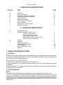
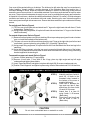
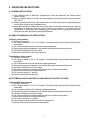
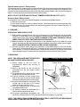
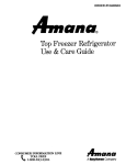
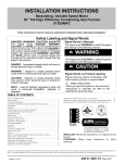
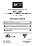
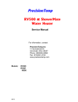
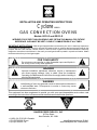
INSTALLATION AND OPERATING INSTRUCTIONS
Cyclone
SERIES
GAS CONVECTION OVENS
Models: BCO-G and GDCO-G
INTENDED FOR OTHER THAN HOUSEHOLD USE. RETAIN THIS MANUAL FOR FUTURE
REFERENCE. OVEN MUST BE KEPT CLEAR OF COMBUSTIBLES AT ALL TIMES.
IMPORTANT INSTRUCTIONS: After the gas supply has been connected to your unit, it is extremely important to
check piping for possible leaks. To do this, use soap and water solution or solutions that are expressly made for this
purpose. DO NOT USE matches, candles, flames, or other sources of ignition since these methods are extremely
dangerous. Instructions to be followed in the event you smell gas should be posted in a prominent location. Obtain
these instructions from your local gas supplier.
!
FOR YOUR SAFETY
Do not store or use gasoline or other flammable vapors and liquids in
the vicinity of this or any other appliance.
!
WARNING
!
Improper installation, adjustment, alteration, service or maintenance
can cause property damage, injury or death. Read the Installation,
Operating and Maintenance Instructions thoroughly before installing or
servicing this equipment.
!
Initial heating of oven may generate smoke or fumes and must be done in
a well-ventilated area. Overexposure to smoke or fumes may cause
nausea or dizziness.
!
WARNING
!
This equipment has been engineered to provide you with year round dependable service when used
according to the instructions in thismanual and standard commercial kitchen practices.
Form # 8898500 4/05
BAKERS PRIDE OVEN CO., INC.
30 Pine Street
New Rochelle, NY 10801
+1 (800) 431-2745 US & Canada
+1 (914) 576-0200 Phone
+1 (914) 576-0605 Fax
[email protected] E-Mail
www.bakerspride.com WebAddress
1
Table of Contents
I. INSTALLATION INSTRUCTIONS
SECTION
A
B
C
D
E
F
G
H
I
J
ITEM
PAGE
Receiving
Set Up / Mounting
Installation with Casters (Optional)
Location and Minimum Clearances
Gas Connections
Electrical Connection
Flue Connection Ventilation
Burner Operation
System Check Rotary Control
Programming Menus
2
3
4
4
4
5
5
6
6
6
II. OPERATING INSTRUCTIONS
A
B
C
D
General Instructions
Operation Sequence Rotary Control
Cook only rotary control
Timed cooking rotary control
Cook and hold- rotary control
Optional steam injection rotary control
To cool down the oven quickly
Cleaning
Servicing
Stacking Instructions
Leg Assembly Instructions
Wiring Diagrams
Parts List & Exploded View
Warranty
7
7
7
7
7
8
8
8
8
9
10
11, 12
13
16
I. INSTALLATION INSTRUCTIONS
A. RECEIVING
Read the notice on the outside carton regarding damage in transit. Damage discovered after opening
the carton is “CONCEALED DAMAGE.” Carrier must be notified immediately to send an inspector and
to furnish forms for claims against the carrier.
When the oven arrives, it should consist of:
A crate or carton containing your new oven (two for a stacked unit).
A carton containing four 31” legs with mounting hardware (set of four 6” legs is supplied for stacked
installations).
A carton containing a Flue Adapter and a Draft Hood. Optional: for Direct Venting (Not available for
EuropeanCommunity Countries).
B. SET UP / MOUNTING:
NOTE:
This appliance must be installed by competent personnel in accordance with the rules in force.
In the U.K., Corgi registered installers (including the regions of British Gas) undertake to work to safe
and satisfactory standards. This appliance must be installed in accordance with the current Gas Safety
(Installation and Use) Regulations and the relevant Building Regulations/IEE Regulations. Detailed
recommendations are contained in the British Standard Codes of Practice B.S. 6172, B.S. 5440: Part 2
and B.S. 6891.
2
Your oven will be packed sitting on its bottom. The skid may be left under the oven for convenience in
further handling. Unpack carefully, avoiding damage to the Stainless Steel front and/or trim. If
concealed damage is found, follow the instructions detailed in Section A (Receiving). Keep the area
around the ovens free and clear of combustible materials. Do not store anymaterials on top of or under
any oven. The provision for adequate air supply to your oven for ventilation and proper gas combustion
is essential. As a minimum, observe the clearances detailed in Section D (Location). Provide adequate
ventilation and make up air in accordance with local codes. Servicing your oven is done through the
front control panel and right side access cover. Ensure that these areas are kept unobstructed for easy
access.
For a single unit: Refer to Figure 4
(1) Tilt Oven over to left-hand side and attach two 31” legs on the right-hand side with three ½” bolts
and washers. Tighten firmly.
(2) Using proper lifting equipment, lift up the left-hand side and attach two 31” legs on the left-hand
side the same way.
For a stack of two ovens: Refer to Figure 3
(1) Remove flue from bottom oven prior to stacking.Whentopovenisproperlypositioned on bottom
oven, re-install the flue back on the bottom oven.
(2) Tilt lower unit over to the left-hand side and position two 6” legs on the right side (one for front and
one for back), secure in place by using 4 bolts (3/8”-16) per leg. Tighten firmly.
(3) Using proper lifting equipment, lift up the left side of the unit and attach the other two legs in the
same way.
(4) Using the lifting equipment, raise the top oven to proper height and slide on top of the bottom
oven. Line up sides and front and fasten to each other at the rear of the units by using a mounting
bracket supplied in the stacking kit.
To assemble an open rack stand: Refer to Figure 1
(1) Loosen 12 bolts (attaching 31” legs) slightly.
(2) Remove 4 inner bolts, 1 from each of the 4 legs, place top right angle and top left angle
underneath and tighten these 4 bolts.
(3) Insert “Open Rack Shelf” and tighten into place with eight 3/8-16 screws, washers and nuts.
(4) Position “Rack Supports” and tighten in place using 4 each of flat washers and 5/16-18 Hex Nuts.
Figure 1
OPEN RACK STAND ASSEMBLY INSTRUCTIONS: BCO-E & GDCO-E
10
8
STEP 1)
6
2
STEP 2)
7
STEP 3)
5
9
4
!
STEP 4)
3
Attach 4 each Item 2 with 16
each 3/8 -16 bolts to the
threaded holes located in
the bottom of the oven or
supplied with leg kit.
Place Item 4 between the
legs and over Item 9 then
attach Item 9 to Item 4 with
16 each 10-32 screws.
Attach Item 5 to Item 10
using 2 each ¼ -20 screws
(Both sides)
Place Item 5 into Item 6 and
into the holes in Item 4.
(Both sides)
CAUTION
Do not store combustible items or materials on racks.
3
!
Fit the Standard Flue Diverter supplied into the hole in the top of the oven for under ventilation hood
installation and secure with screws. For direct venting, FlueAdapter and Draft Hood must be placed into
the hole on top of the oven.
C. INSTALLATIONWITHCASTERS (OPTIONAL): Refer to Figure 4
Four casters (two with wheel brakes) and the mounting hardware are packed and included in the
shipment if ordered. Install casters with wheel brakes on the front of the unit. Installation of the unit
should be madewithaconnector that complies with the latest edition of the Standard for Connectors for
Movable GasAppliances ANSI Z21.69 in the USA (CAN CSA-6.16 in Canada) and a quick-disconnect
device that complies with the latest edition of the standard for quick disconnect devices for use with gas
fuel ANSI Z21.41 in the USA (CSA 6.9 in Canada). Adequate means must be provided to limit the
movement of the appliance without depending on the connector and any quick disconnect device or its
associated piping to limit appliance movement.
The restraint should be attached to the rear legs of the oven on which casters are mounted. If
disconnect of the restraint is necessary, the restraint should be immediately reconnected after the
appliance has been returned to its originally installed position.
D. LOCATIONAND MINIMUM CLEARANCES:
Move the oven to its final location keeping the minimum clearance from the back of the oven to the wall.
This clearance is necessary for safe operation and to provide proper air flow to the burner chamber.
MINIMUM CLEARANCES FROM COMBUSTIBLE AND NONCOMBUSTIBLE CONSTRUCTION
Under Ventilation Hood
Direct Venting
RIGHT WALL
1”
1”
LEFT WALL
1”
3”
REAR WALL
3”
3”
!
SUITABLE FOR INSTALLATION ON COMBUSTIBLE FLOOR WHEN
INSTALLEDWITHLEGSORCASTERSPROVIDED.
!
!
CAUTION: DO NOT SET THE OVEN WITH ITS BACK FLAT AGAINST THE
WALL. IT WILL NOT OPERATE PROPERLY UNLESS THERE IS AT LEAST
THREE INCHES BREATHING SPACE BEHIND THEOVEN
!
E. GAS CONNECTION:
The ovens should not be installed on the same gas supply line with space heaters, boilers or other gas
equipment with high intermittent demand.
The installation of the oven must conform to the latest local codes or National Fuel Gas Code, ANSI
Z223.1, Natural Gas Installation Code, CAN/CGA-B149.1, or the Propane Installation Code,
CAN/CGA-B149.2.
The appliance must be isolated from the gas supply piping system by closing its manual shut-off valve
during any pressure testing of the gas supply piping system at test pressures equal to or less than ½
psig (3.45kpa). The appliance and its shut-off valve must be disconnected from the gas supply piping
system during any pressure testing of that system at test pressures in excess of ½ psig (3.45kpa).
Use a pipe joint compound that is resistant to the action of liquefied petroleum gases when making gas
connections. For Propane gas, use at least ½” (13 mm) pipe or tubing with a 5/8” (16 mm) inside
diameter. For Natural gas, use ¾” (19 mm) pipe.
4
The gas pressure regulator is part of the combination valve and is adjusted to yield a pressure of 3.5”
water column (9 mbar) for Natural Gas. If the oven is ordered for use on Propane Gas or Butane, the
pressure regulator in the combination valve is preset at the factory to yield a pressure of 10” water
column (25 mbar). NOTE: No external regulator is required.
Gas supply pressure in the European Community countries should be as below.
Gas Type
Supply Pressure
G20
G25
G20/25
G30
G31
20 mbar
25 mbar
20/25mbar
30 or 50 mbar depending on country
30, 37, or 50mbardepending on country
A separate shut-off valve for each oven must be provided. It should be as close as possible to the place
where the gas line goes into the oven. It must be located such that it is easily accessible.Whenstacking
with another oven, two shut-off valves, one for each of the two ovens,mustbeprovided.
After the Gas Supply has been connected, it is extremely important to check all the piping for
leaks. Use a soap and water solution or a product expressly made for this purpose. Do not use
matches, candles or a flame and so forth to check leaks since these methods are extremely
dangerous.
F. ELECTRICAL CONNECTION:
The oven, when installed, must be electrically grounded in accordance with local codes and/or the
latest edition of the National Electrical Code ANSI/NFPA No. 70 in the USA (Canadian Electrical Code
CSAStandard C22.1, Part 1 in Canada).
In Europe, the appliance must be connected by an earthen cable to all other units in the complete
installation and, thence, to an independent earth connection in compliance with EN 60335-1 and/or
local codes.
The electric motor, all the related switches, interior lights, and the timer/buzzer are all connected
through the 6-foot (1829 mm) power supply cord located at the rear of the oven. The supply cord must
be plugged into a properly grounded, three-prong receptacle. DO NOT CUT OR REMOVE THE
GROUNDING PRONG FROM THE PLUG.
Normal factory connections aremadefor120voltsA.C., 60 hz, Service in USA andCanada or 240 volts
A.C., 50 hz service in European community countries. Other voltages can be supplied upon request.
Electrical characteristics of this unit can be found on the rating plate located on the right side of the unit.
This unit is provided with a permanently lubricated electric motor. A wiring diagram may be found on the
back of the service panel on the right-hand side and in thismanual.
G. FLUE CONNECTION VENTILATION:
Installation under ventilation hood (standard):
If the oven is not vented directly and is installed under a ventilation hood, the unit is ready to be installed
as is. Local inspectors and ventilation specialists should be consulted so that the design and the
installation of the hood conform to local/municipal codes. In the U.K., follow ventilation requirements as
detailed in B.S. 5440.
5
Optional direct venting (not available for European community countries):
If direct venting, a flue adapter and a draft hood are required to be installed. They prevent the flue gases
leaving the oven to be affected by the air pressure changes on the outside of the flue stack extending
out of the building. The flue pipe from the draft hood must not run downwards at any point from the oven
to the final outlet. It should always slant slightly upwards. For best results, is should rise straight up. The
venting system shall be in accordancewith the National Fuel Gas Code,ANSI Z223.1 / NFPA54 and or
the CSA B149.1, NaturalGasandCSA B149.2, Propane InstallationCodes, and local codes.
NOTE: DO NOT PUT A DAMPER IN THE FLUE AND DO NOT CONNECT A BLOWER DIRECTLY
TO THE FLUE.
If the flue runs directly to the free air outside the building, use a wind deflector or a UL listed vent cap at
the end of the pipe. Termination of the vent must be at least two feet above the highest part of the roof
within ten feet. REF:AGACATALOG NO. XH0474.
H. BURNER OPERATION:
The oven burner flame should always have a blue appearance. This indicates a good mixture of air and
gas. When using LP gas, the flame will have a blue-yellow appearance. There may be intermittent
yellow-orange flame noticed. This is caused by dust particles burning in the flame.
I. SYSTEM CHECK- ROTARYCONTROL:
(1) Open the oven door.
(2) Turn Selector Switch to “HI.” The indicator light near Selector Switch and oven light will
illuminate.
(3) Close the door. Oven lights will go off and fan will run. Make sure fan is rotating clockwise
looking from front.
(4) Press Oven Light switch. Oven light will go on and will go off when switch is released.
(5) Turn Gas Cock Dial to “ON” position (only for USA and Canada).
(6) Turn the thermostat knob. The indicator light near the thermostat will illuminate and the
burners will come on.
(7) Turn the Timer Knob and set a time of 2 minutes. At the end of 2 minutes, you should hear
the buzzer. Turn the timer knob to “0”, to stop the buzzer.
(8) Open the oven doors. Oven lights will go on and burners and fan will go off.
(9) Turn Selector Switch to “Cool Down” position. The fan will run to cool down the oven.
(10) Turn Selector Switch to “0” position.
(11) Close the oven doors.
NOTE: OVEN STARTS HEATING AS SOON AS THE SET TEMPERATURE IS HIGHER THAN THE
OVEN TEMPERATURE WITH THE OVEN DOORS CLOSED AND THE SELECTOR SWITCH NOT
IN“0”POSITION.
THERMOSTAT INDICATOR LIGHT GOES OUT WHEN OVEN REACHES SET TEMPERATURE
AND COMES ONWHENOVENISHEATINGUP.
IN THE EVENT OF POWER FAILURE, THE OVEN WILL NOT OPERATE. RESTORATION OF
POWERAFTERANYDURATION,WILLRETURN UNIT TO NORMAL OPERATION.
J. PROGRAMMINGMENUS (for units with digital controls):
Refer to C&H - 3 Plus Controller Operating/Programming Instructions Manual.
6
II. OPERATING INSTRUCTIONS
A. GENERAL INSTRUCTIONS:
(1) This equipment has an Electronic Temperature Control and Electronic Hot Surface Direct
Ignition System.
(2) Due to increased efficiency of this oven, the temperature of standard recipes may be reduced
50°F (30°C).
(3) Always load each shelf evenly. Space pans away from each other and from sides and back of
oven to allow maximum air flow between them.
(4) Large tempered glass windows and interior lights allow a close check on the product, making it
unnecessary to frequently open the doors. Products cook faster in a convection oven as
compared to a conventional oven. Depending on the product and the type of pans used, time
saving may run from 20 percent to as high as 50 percent.
B.OPERATION SEQUENCE ROTARYCONTROL:
Cook only rotary control:
(1) Close the oven doors.
(2) Turn Selector Switch to “HI” or “LO” position. The indicator light near the Selector Switch will be
illuminated.
(3) Turn the thermostat knob to the desired cooking temperature.
(4) Upon reaching the set temperature, the indicator light near the thermostat will go out.
(5) Load the ovenwithproduct to be cooked.
(6) Remove the product from the oven when done.
Timed cooking rotary control:
(1) Close the oven doors.
(2) Turn Selector Switch to “HI” or “LO” position. The indicator light near the Selector Switch will be
illuminated.
(3) Turn the thermostat knob to the desired cooking temperature.
(4) Upon reaching the set temperature, the indicator light near the thermostat will go out.
(5) Load the ovenwithproduct to be cooked.
(6) Turn the timer knob to the desired bake time and timer will start counting down.
(7) When timer reaches zero, a buzzer will sound.
(8) Turn the timer knob to “O” position.
(9) Remove the product from the oven.
NOTE: TIMER ISASIGNAL DEVICEONLYANDDOES NOT CONTROL THE OVEN.
Cook and Hold Rotary Control:
(1) Close the oven doors.
(2) Turn Selector Switch to “HI” or “LO” position. The indicator light near the Selector Switch will be
illuminated.
(3) Turn the thermostat knob to the desired cooking temperature.
(4) Upon reaching the set temperature, the indicator light near the thermostat will go out.
(5) Load the ovenwithproduct to be cooked.
(6) Turn the timer knob to the desired bake time and timer will start counting down.
(7) When timer reaches zero, a buzzer will sound.
(8) Turn the Timer knob to “O” position.
(9) Turn the thermostat knob to the desired hold temperature.
(10) Remove the product from the oven when needed.
7
Optional steam injection: Rotary control:
The solenoid valve for steam injection is mounted behind the service panel on the right-hand side of the
unit. The electronic timer is preset at the factory. A ¼” copper tubing is provided on the Solenoid Valve
for water hookup with a compression fitting.After the water hookup ismade, make sure that there are no
leaks. For steam injection, press the Steam switch momentarily.
NOTE: DO NOT USE STEAM INJECTION AT TEMPERATURES BELOW 275°F (135°C).
Oven cool down Rotary control:
To cool down the oven to a lower desired temperature, follow the steps detailed below.
(1) Open the oven doors.
(2) Turn Selector Switch to “oven cool down” position. Fanwillnowoperate and cool down the oven.
(3) When the oven has cooled down to the desired temperature, turn the Selector Switch to “O”
position. Close oven doors.
C.CLEANING:
CLEAN ONLY WHEN OVEN IS COLD
(1) With porcelain enamel interiors, this oven is designed to be as maintenance free as possible.
However, for best results, the oven should be cleaned regularly. Enameled interiors can be
easily cleaned with oven cleaners. KEEP CLEANING FLUIDS AWAY FROM ELECTRICAL
WIRES, LIGHT SOCKETS, SWITCHESANDCONTROLPANEL.
(2) Baked on splatter, oil, grease or discoloration on the stainless steel front or inside of the oven
may be removed with the stainless steel cleaner supplied or any other similar cleaning agent.
NOTE: ALWAYS RUB THE STAINLESS STEEL ALONG THE GRAINS.
(3) To clean the blower wheel, remove and immerse in ammoniated water for 20 to 25 minutes.
Then, scrub it off with a small, stiff brush. The same procedure can be followed for wire racks and
rack supports. To remove the blower wheel, loosen the set screws (2) on the hub of the blower
wheel and tighten the 3/8” wheel puller bolt (supplied) in center of the hub (See Figure 2).
D. SERVICING:
NOTE: THIS APPLIANCE MUST BE SERVICED
BYANAUTHORIZED SERVICEAGENT.
Figure 2
Cleaning The Blower Wheel
Blower Wheel
(1) Power supply to the unit must be
disconnected before any service is
performed.
(2) Most of the service on the unit can be
performed from the front and/or control
Set Screws (2)
panel side.
(3) For proper servicing, access to the control
panel side of the unitwillberequired.
Motor
(4) It will be necessary to have access to the
back of the oven for service needs related
to the gas supply and electric power supply.
(5) A system wiring diagram is provided in this
manual and on the back of the service
panel on the right side of the oven.
(6) This unit is provided with a permanently
lubricated electricmotor.
Wheel Puller Bolt 3/8”-Hex
(7) All servicing should be performed by a
factory-authorized technician only.
(8) For proper maintenance and repairs, call
the factory toll free (800-431-2745) for an authorized service agency in your area.
NOTE: THE VENTILATION SYSTEM MUST BE INSPECTED AT LEAST EVERY SIX MONTHSAND
MAINTAINED CLEAN AND FREE OF OBSTRUCTIONS.
8
Figure 3
STACKING INSTRUCTIONS FOR: BCO-G & GDCO-G CONVECTION OVENS
Attach part # 21818062 with
6 each 8-32 stainless screws
Material: 14 ga
201 Stainless
2
1
3
Remove the outer and inner flue from the
bottom oven before placing the top oven (to
prevent damaging the bottom oven’s flue).
Re-install after top oven is positioned.
Item 1
Item 2
E3770A
E3771A
9
Item 3
3/8”-16 Bolt
LEG ASSEMBLY INSTRUCTIONS-MODEL: BCO-G & GDCO-G
Figure 4
WITH PLATE CASTER
6
Item
1
2
3
4
5
6
7
1
P/N
21818092
8633102
8227700
8509300
8435000
82447-00
8633101
Description
Leg, 25" SS Weldment Assy
Caster, 5” Swivel W/Top Plate
Hex Hd 5/16-18 X ¾ Bolt #5 Zn
Washer, Flat SAE, 5/16
Hex-nut 5/16-18
Hex Hd. 3/8-16 X .750 #5
Caster, 5" Swivel W/Plate & Brake
3
1.
2.
3.
4
5
2
Attach two item 2 to two item 1 using item 3, 4 and 5.
Attach two item 7 to two item 1 using item 3, 4 and 5.
Using proper lifting equipment attach item 1 to the 4
corresponding hole patterns located in the bottom
of the oven with item 6.
7
WITHOUT PLATE CASTER
1
Item
1
2
3
4
5
6
6
1.
2.
3
4
5
2
10
P/N
21818095
8633515
8227700
8509300
8435000
82447-00
Description
Leg, 25" Weldment Assy
Foot Insert, Adjustable
Hex Hd 5/16-18 X 3/4 Bolt #5 Zn
Washer, Flat, SAE, 5/16
Hex-Nut 5/16-18
Hex Hd. 3/8-16 X .750 #5
Attach two item 2 to two item 1 using item 3, 4 and 5.
Using proper lifting equipment attach item 1 to the 4
corresponding hole patterns located in the bottom
of the ovenwith item 6.
SINGLE-PHASE 120V WIRING DIAGRAM (PUSH-BUTTON CONTROL)
LOW
GREEN LIGHT
26
10
HIGH
29
BLACK
WHITE
120V
9
BUTTSPLICE
28
TRANSFORMER
GROUND
4 POSTION
SWITCH
YELLOW
1
2
3 4
20
24V
BLUE
P1 P2 P3 P4
42
39
RELAY
13
LIGHTS
44
36
35
38
37
T10
T11
33
32
PROBE
L1-24VAC
T13
T12
CH104
CONTROL
THERMOSTAT
T6
17
T9
T8
T1
40
120V
8
44
8
4
13
21
9
10
41
5
4
7
43
18
22
5
23
31
IGNITER
COMBINATION VALVE
14
42
12
2
2
31
1
23
3
1
11
40
DOOR SWITCH
33
19
34
12
PUSHBUTTON
SWITCH
20
22
16
T2 T3 T4 T5
6
17
GROUND
POWER SWITCH
32
GROUND STUD
11
COM
16
VALVE HOT
FLAMESENSE
T7
FAN
MOTOR
14
18
IGNITOR
DOOR
SWITCH
MOT
GROUND STUD
PROBE
3
29
26
GROUND STUD
15
34
41
15
21
CENTRIFUGAL SWITCH
19
FLAME SENSOR
10
HIGH
LOW
29
POWER
LIGHT
26
8
4 POS
SWITCH
28
BLACK
1 2 3 4
WHITE
120V
BUTT SPLICE
9
P1 P2 P3 P4
TRANSFORMER
GROUND
CENTRIFUGAL SWITCH
32
13
T-STAT LIGHT
YELLOW
BLUE
FAN
MOTOR
24V
PROBE
35
T-STAT
L1-24VAC
THERMOSTAT
T6
T7
T8 T9 T10 T11
VALVE HOT
GROUND
4
17
FLAME SENSE
13
14
GROUNDSTUD
2
60 MIN
TIMER
COMBINATION VALVE
7
3
9
GROUNDSTUD
4
DOOR SWITCH
18
3
23
IGNITER
19
3
1
7
1
12
11
2
FLAME SENSOR
33
40
41
32
37
6
10
NO
14
4
34
POWER
SWITCH
33
38
5
2
15
36
31
6
1
22
BUTTSPLICE
23
GROUNDSTUD
31
MOT
29
COM
22
19
BUZZER
39
26
11
20
21
LIGHTS
20
GROUND STUD
17
12
15
NC
16
16
LIGHT
SWITCH
COM
18
IGNITOR
21
BCO-G & GDCO-G
30 Pine Street • New Rochelle • New York • 10801
BAKERS
PRIDE
914 / 576 - 0200
914 / 576 - 0605 fax
1 - 800 - 431 - 2745 US & Canada
www.bakerspride.com web address
Cyclone
Full Size Gas Convection Oven
PARTS LIST
SERIES
Model Number: BCO-G & GDCO-G
Type of Gas: Natural
L.P.
Other
Serial Number:
Voltage/Phase: 115/1
208-240/1
230/1 (CE)
4/05
Note: When ordering, ALWAYS specify Part #, Model #, Serial #,Voltage/Phase & type of Gas.
13
Page 1 of 4
14
15
BAKERS PRIDE LIMITED WARRANTY
30 Pine Street New Rochelle, New York 10801
914 / 576 - 0200 • US & Canada: 1 - 800 - 431 - 2745 • fax 914 / 576 - 0605
WHAT IS COVERED
This warranty covers defects in material and workmanship under normal use, and applies only to the original purchaser
providing that:
! The equipment has not been accidentallyorintentionallydamaged, altered or misused;
! The equipment is properly installed, adjusted, operated and maintained in accordance with National and local
codes, and in accordance with the installation instruction provided with the product;
! The serial number rating plate affixed to the equipment has not been defaced or removed.
WHO IS COVERED
This warranty is extended to the original purchaser and applies only to equipment purchased for use in the U.S.A.
COVERAGE PERIOD
Cyclone Convection Ovens: BCOModels: One (1) Year limited parts and labor; (1) Year limited doorwarranty.
GDCOModels: Two (2) Year limited parts and labor; (2) Year limited door warranty.
CO11 Models: Two (2) Year limited parts and labor; (5) Year limited doorwarranty.
All Other Products: One (1) Year limited parts and labor. Warranty period begins the date of dealer invoice to customer or
ninety (90) days after shipment date from BAKERS PRIDE - whichever comes first.
WARRANTY
COVERAGE
This warranty covers on-site labor, parts and reasonable travel time and travel expenses of the authorized service
representative up to (100) miles, round trip, and (2) hours travel time. The purchaser, however, shall be responsible for all
expenses related to travel, including time, mileage and shipping expenses on smaller counter models that may be carried into
a Factory Authorized Service Center, including the following models: PX-14, PX-16, P18, P22S, P24S, PD-4, PDC, WS
Series and BK-18.
EXCEPTIONS
All removable parts in BAKERS PRIDE Char-broilers, including but not limited to: Burners, Grates, Radiants, Stones and
Valves, are covered for a period of SIXMONTHS.
All Ceramic Baking Decks are covered for a period of THREE MONTHS. The installation of these replacement decks is the
responsibility of the purchaser.
The extended Cyclone door warranty years 3 through 5 is a parts only warranty and does not include labor, travel, milage or
any other charges.
EXCLUSIONS
Failures caused by erratic voltages or gas supplies,
Unauthorized repair by anyone other than a BAKERS PRIDE
Factory Authorized Service Center,
Damage in shipment,
Alteration, misuse or improper installation,
Thermostats and safety valves with broken capillary tubes,
Accessories — spatulas, forks, steak turners, grate lifters,
oven brushes, scrapers, peels, etc.,
Freight — other than normal UPS charges,
Ordinary wear and tear.
Negligence or acts of God,
Thermostat calibrations after (30) days from equipment
installation date,
Air and Gas adjustments,
Light bulbs,
Glass doors and door adjustments,
Fuses,
Char-broiler work decks and cutting boards,
Tightening of conveyor chains,
Adjustments to burner flames and cleaning of pilot burners,
Tightening of screws or fasteners,
INSTALLATION
Leveling and installation of decks, as well as proper installation and check out of all new equipment — per appropriate
installation and use materials — is the responsibility of the dealerorinstaller, notthemanufacturer.
REPLACEMENT
PARTS
BAKERS PRIDE genuine Factory OEM parts receive a (90) day materials warranty effective from the date of installation by a
BAKERS PRIDE Factory Authorized Service Center.
This Warranty is in lieu of all other warranties, expressed or implied, and all other obligations or liabilities on the manufacturers part. BAKERS PRIDE
shall in no event be liable for any special, indirect or consequential damages, or in any event for damages in excess of the purchase price of the unit. The
repair or replacement of proven defective parts shall constitute a fulfillment of all obligations under the terms of this warranty.
Form #U4177A 3/04
16