1
r XMnN
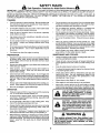
MODEL NUMBER 917.377201
OWNER'SMANUAL
o Assembly
Operation
Customer
Responsibilities
Service
Adjustments
Repair Parts
Caution:
Read and Follow
all Safety Rules
and Instructions
Before Operating
This Equipment
160904
05.20.97
VBL
Printed in U.S.A_
SAFETY RULES
Safe Operation
Practices
for Walk-Behind
Mowers
IMPORTANT:
THIS CUTTING MACHINE IS CAPABLE OF AMPUTATING
HANDS AND FEET AND THROWING
OBJECTS.
FAILURE TO OBSERVE THE FOLLOWING SAFETY INSTRUCTIONS
COULD RESULT IN SERIOUS INJURY OR DEATH.
SAFETY STANDARDS REQUIRE OPERATOR PRESENCE CONTROLS TO MINIMIZE THE RISK OF INJURY. YOUR UNIT IS
EQUIPPED WITH SUCH CONTROLS.
DO NOT ATTEMPT TO DEFEAT THE FUNCTION OF THE OPERATOR PRESENCE
CONTROLS UNDER ANY CIRCUMSTANCES.
TRAINING:
•
Read this operator's manual carefully. Become familiar with
the controls and know how to operate your mower properly.
Learn how to quickly stop mower.
•
Do not continue to run your mower if you hit a foreign object.
Follow the procedure outlined above, then repair any damage before restarting and operating you mower,
•
Do not allow children to use your mower. Never allow adults
to use mower without proper instructions.
•
Do not change the governor settings or overspeed the
engine. Engine damage or personal injury may result.
•
Keep the area of operation clear of atl persons, especially
small children and pets.
•
Do not operate your mower if it vibrates abnormally. Excessive vibration is an indication of damage; stop the engine,
safely check for the cause of vibration and repair as required.
•
Use mower only as the manufacturer
scribed in this manual.
•
Do not run the engine indoors.
ous.
•
Do not operate mower if it has been dropped or damaged in
any manner, Always have damage repaired before using
your mower.
•
•
Do not usa accessory attachments that are not recommended
by the manufacturer. Use of such attachments may be
hazardous.
Never cut grass by pulling the mower towards you. Mow
across the face of slopes, never up and down or you might
Ioseyourfooting. Do notmowexcessivelysteepslopes.
Use
caution when operating the mower on uneven terrain orwhen
changing directions - maintain good footing.
•
•
The blade turns when the engine is running,
Never operate your mower without proper guards, plates,
grass catcher or other safety devices in place.
intended and as de-
Exhaust fumes are danger-
PREPARATION:
MAINTENANCE
•
•
Check the blade and the engine mounting
sure they are tightened properly.
•
Check all bolts, nuts and screws at frequent intervals for
proper tightness to be sure mower is in safe working condition.
•
Keep a!l safety devices in place and working.
•
To reduce fire hazard, keep the engine free of grass, leaves
or excessive grease and oil.
•
Check grass catcher often for deterioration and wear and
replace worn bags. Use only replacement bags that are
recommended by and comply with specifications of the
manufacturer of your mower.
•
Always keep a sharp blade on your mower.
•
Allow engine to cool before storing in any enclosure.
•
Never store mower with fuel in the tank inside a building
where fumes may reach an open flame or an ignition source
such as a hot water heater, space heater, clothes dryer, etc.
Always thoroughly check the area to be mowed and clear it of
all stones, sticks, wires, bones, and other foreign objects.
These objects wilt be thrown by the blade and can cause
severe injury.
•
Always wear safety glasses or eye shields when starting and
while using your mower.
•
Dress properly. Do not operate mower when barefoot or
weadng open sandals. Wear only solid shoes with good
traction when mowing,
•
Check fuel tank before starting engine. Do not fill gas tank
indoors, when the engine is running o rwhen the engine is hot.
Allow the engine to cool for several minutes before filling the
gas tank. Clean off any spilled gasoline before starting the
engine.
•
•
Always make wheel height adjustments before starting your
mower. Never attempt to do this while the engine is running.
Mow only in daylight or good artificial light.
AND STORAGE:
bolts often to be
OPERATION:
•
Keep your eyes and mind on your mower and the area being
cut. Do not let other interests distract you.
•
Do not mow wet or slippery grass. Never run while operating
your mower. Always be sure of your footing - keep a firm hold
on the handles and walk.
•
Do not put hands or feet near or under rotating parts. Keep
clear of the discharge opening at all times.
•
Always stop the engine whenever you leave or are not using
your mower, or before crossing driveways, walks, roads, and
any gravel-covered areas.
•
Never direct discharge of material toward bystanders nor
allow anyone near the mower while you are operating it.
•
Before cleaning, inspecting, or repaidng your mower, stop the
engine and make absolutely sure the blade and all moving
parts have stopped. Then disconnect the spark plug wire and
keep it away from the spark plug to prevent accidental
starting.
&
Look for this symbol to point out important safety precautions. It means
CAUTION!H BECOMEALERT!!! YOUR
SAFETY IS INVOLVED.
CAUTION: Always disconnect spark
plug wire and place wire where it cannot contact spark plug in order to prevent accidental starting when setting
up, transporting, adjusting or making •
repairs.
WARNING
The engine exhaust from this product contains chemicals known to the State of California to cause cancer, birth defects, or other
reproductive
harm.
PRODUCT
CONGRATULATIONS
on your purchase of a Sears Lawn
Mower. It has been designed, engineered and manufactured to give you the best possible dependability and
performance.
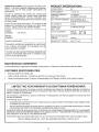
SPECIFICATIONS
HORSEPOWER:
5.5
DISPLACEMENT:
11.5 CU. IN.
Should you experience any problem you cannot easily
remedy, please contact your nearest Sears Authorized
Service Center/Department.
We have competent, welltrained technicians and the proper tools to service or repair
this lawn mower.
GASOLINE CAPACITY
AND TYPE:
!.5 QUARTS
UNLEADED REGULAR
Please read and retain this manuat. The instructions will
enable you to assemble and maintain your lawn mower
}roperly. Always observe the "SAFETY RULES".
OIL CAPACITY:
20 QZS.
SPARK PLUG:
(GAP: .030")
CHAMPION
RJ19LM
VALVE CLEARANCE:
INTAKE:
EXHAUST:
.00@- .008
.004 - .008
MODEL
NUMBER
OIL TYPE (APt-SF/SGiSH): SAE 30 {ABOVE 32°F)
SAE 5W-30 {BELOW 32°F)
917.377201
SERIAL
NUMBER
SOLID STATE IGNITION
AIR GAP:
,0125 IN.
DATEOFPURCHASE
BLADE BOLT TORQUE:
35-40 FT. LBS.
THE MODEL AND SERIAL NUMBERS WILL BE FOUND
ON A DECAL ATTACHED TO THE REAR OF THE
LAWN MOWER HOUSING
YOUSHOULDRECORDBOTHSERIALNUMBERAND
DATE OFPURCHASEAND
KEEPIN A SAFE PLACE
FOR FUTURE REFERENCE.
MAINTENANCE
AGREEMENT
A Sears Maintenance Agreement is available on this product. Contact your nearest Sears store for details.
CUSTOMER
RESPONSIBILITIES
*
Read and observe the safety rules.
=
Follow a regular schedule in maintaining, caring for and using your lawn mower.
,
Follow the instructions under "Customer Responsibilities"
LIMITED TWO YEAR WARRANTY
and "Storage" sections of this owner's manual.
ON CRAFTSMAN
POWER MOWER
For two (2) years from date of purchase, when this Craftsman Lawn Mower is maintained, lubricated, and tuned up
according to the operating and maintenance instructions in the owner's manual, Sears will repair free of charge any
defect in material or workmanship.
If this Craftsman Lawn Mower is used for commercial or rental purposes, this warranty applies for only 90 days from
the date of purchase.
This Warranty does not cover:
-
Expendable items which become worn during normal use, such as rotary mower blades, blade adapters, belts,
air cleaners and spark plug.
=
Repairs necessary because of operator abuse or negligence, including bent crankshafts and the failure to maintain
the equipment according to the instructions contained in the owner s manual.
WARRANTY SERVICE IS AVAILABLE BY RETURNING THE CRAFTSMAN POWER MOWER TO THE NEAREST
SEARS SERVICE CENTER/DEPARTMENT
IN THE UNITED STATES. THIS WARRANTY APPLIES ONLY WHILE
THIS PRODUCT IS IN USE IN THE UNITED STATES.
This Warranty gives you specific legal rights, and you may also have other rights which vary from state to state.
SEARS, ROEBUCK AND COo, D/817 WA, HOFFMAN ESTATES, ILLINOIS
3
60179
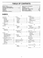
LE OF CONTENTS
SAFETY RULES ............................................................
2
PRODUCT SPECIFICATIONS ...................................... 3
CUSTOMER RESPONSIBJL|TIES ....................... 3, 9=11
WARRANTY .................................................
................. 3
ASSEMBLY ...................................................................
5
OPERATION ..................................................................
6
MAINTENANCE SCHEDULE ........................................ 9
SERVICE AND ADJUSTMENTS ................................. 12
STORAGE ...................................................................
14
TROUBLESHOOTING .................................................
23
REPAIR PARTS- LAWN MOWER ........................ 15-19
REPAIR PARTS- ENGINE .................................... 20-22
PARTS ORDERING!SERVICE ....................................
24
DEX
E
A
Accessories ....................................
Adjustments:
Carburetor .............................
Drive Bett ...............................
Engine Speed ........................
Handle Height ........................
Height of Cut ............................
Air Filter:
Replacement .........................
Service ...................................
Assembly ........................................
5
13
12
13
13
7
11
11
5
B
Blade:
Sharpening ............................
Replacement .........................
10
10
C
Controls:
Drive Control ............................
Engine Zone Control ................
Engine Speed Control .............
Operator Presence
Control Bar ..............................
6
6
6
6
Customer Responsibilities ..... 3, 9-11
Air Filter .................................
!1
Blade Care/Replacement ...... 10
Drive Wheels ......................... 10
Engine ...................................
11
Lubrication ............................... 9
Spark Plug ............................. 11
Cutting Leveis ................................ 7
Engine:
Air Filter .................................
QiI Change .............................
Oil Level .................................
Oil Type .................................
Starting ....................................
Stopping ..................................
Storage ..................................
11
11
11
11
8
8
14
Operation:
Drive Control ............................
Engine Control .........................
Grass Catcher .........................
Mower ......................................
Operator Presence
Control Bar ..............................
Options:
Accessories
F
7
7
7
7
7
.............................
5
R
Fuel:
Capacity ................................... 3
Storage .................................. 14
Type .........................................
8
H
Repair Parts:
Engine ..............................
Lawn Mower .....................
Responsibilities,
20-22
15-19
Customer .... 3, 9-tl
S
Handle Adjustment:
Assembly ................................. 5
Cutting Height ........................ 13
L
Lubrication:
Engine ................................... 11
Lawn Mower ............................ 9
Safety Rules ...................................
2
Service and Adjustments .............
Carburetor .............................
Drive Belt ...............................
Engine Speed ........................
Handle ...................................
12
13
12
13
13
Spark Plug ....................................
11
Specifications .................................
3
M
Speed Control:
Engine .....................................
7
Maintenance Agreement ................ 3
Maintenance Schedule ................... 9
Starting the Engine .........................
8
Mowing Tips ...................................
8
O
Storage .........................................
11
14
Trouble Shooting Chart ................ 23
W
Warranty .........................................
&
8
14
T
Oil:
Engine ...................................
Storage ..................................
Stopping the Engine .......................
3
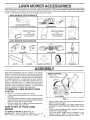
LAWN
ACC
These accessories were available when this lawn mower was produced. They are also available at most Sears retail outlets
and service centers. Most Sears stores can also order repair parts for you, when you provide the model number of your lawn
mower. Some of these accessories may not apply to your lawn mower.
LAWN
MOWER
PERFORMANCE
f
CLIPPING DEFLECTOR
FOR REAR DISCHARGE LAWN MOWERS
\
\
MULCHER KITS
GRASS CATCHERS
FOR
REAR DISCHARGE
LAWN MOWERS
STABlUZER
FOR
SIDE DISCHARGE
GRASS
LAWN CATCHERS
MOWERS
I_
GAS CANS
LAWN
MOWER
MAINTENANCE
AIR FILTERS
MUFFLERS
BLADES
BLADE ADAPTERS
SPARK PLUGS
WHEELS
ENGINE OIL
i, irlll
ASSEMBLY
Read these instructions and this manual in its entirety
before you attempt to assemble or operate your new lawn
mower. Your new lawn mower has been assembled atthe
factory with the exception of those parts left unassembled
for shipping purposes. All parts such as nuts, washers,
bolts, etc., necessary to complete the assembly have been
placed in the parts bag. To ensure safe and proper
operation of your lawn mower, all parts and hardware you
assemble must be tightened securely. Use the correct
tools as necessary to ensure proper tightness.
TO REMOVE
CARTON
=
,
=
OPERATOR PRESENCE
CONTROLBAR
LiFT UP
LAWN MOWER FROM
MOWING POS_TION
Remove loose parts included with mower.
Cut down two end corners of carton and lay end panel
down flat.
Remove all packing materia s except padd ng between
upper and lower handle and padding holding operator
presence control bar to upper handle.
Roll lawn mower out of carton and check carton thoroughly for additional loose parts.
LOWER HANDLE
FiG. 1
•
HOW TO SET UP YOUR LAWN
MOWER
TO UNFOLD
HANDLE
,
(See Fig= 1)
IMPORTANT:
UNFOLD HANDLE CAREFULLY SO AS
NOT TO PINCH OR DAMAGE CONTROL CABLES.
,
5
Raise handles until lower handle section locks into
place in mowing position.
Raise protective padding, raise upper handle section
into place on lower handle and tighten both handle
knobs.
Remove handle padding holding operator presence
control bar to upper handle.
Your lawn mower handle can be adjusted for your
mowing comfort.
Refer to "Adjust HandW' in the
Service and Adjustment section of this manual.
OP
KNOW YOUR LAWN MOWER
READ THiS OWNER'S MANUAL AND SAFETY RULES BEFORE OPERATING YOUR LAWN MOWER. Compare the
illustrations with your lawn mower to familiarize yourself with the location of various controls and adjustments. Save this
manual for future reference.
These symbols
their meaning.
may appear on your lawn mower or in literature supptied with the product. Learn and understand
- i\1
CAUTION
OR WARNING
OPERATOR
ENGINE
ON
PRESENCE
ENGINE
OFF
CONTROL
FAST
SLOW
CHOKE
FUEL
OIL
DANGER, KEEP HANDS
AND FEET AWAY
BAR
DRIVE CONTROL
ENGINE ZONE CONTROL
CABLE
LEVER
DRIVE CONTROL
STARTER HANDLE
HANDLE
KNOB
,1. GASOLINE
ENGINE OiL CAP WiTH DIPSTICK
FILL CAP
I
ENGINE SPEED CONTROL
LEVER
DRIVE COVER
MULCNER
DOOR
WHEEL ADJUSTER
HOUSING
(ON EACH WHEEL)
MEETS CPSC SAFETY
REQUIREMENTS
Sears rotary walk-behind power lawn mowers conform to the safety standards of the American National Standards Institute
and the U.S. Consumer Product Safety Commission. The blade turns when the engine is running.
OPERATOR PRESENCE CONTROL - must be held down
to the handle to start the engine. Release to stop the
engine.
DRIVE CONTROL LEVER - used to engage power-propelled forward motion of lawn mower.
MULCHER DOOR - allows cOnversion to discharge or
bagging operation.
ENGINE SPEED CONTROL LEVER - must be in the fast
(,_) position for starting and mowing.
PRIMER - pumps additional fuel from the carburetor to the
cylinder for use when starting a cold engine.
STARTER HANDLE - used for starting the engine.
6
OPERATION
The operation of any lawn mower can result in foreign objects thrown into the eyes, which can
result in severe eye damage. Always wear safety glasses or eye shields while operating your
lawn mower or performing any adjustments or repairs. We recommend a wide vision safety
mask over the spectacles or standard safety glasses.
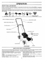
HOW TO USE YOUR LAWN MOWER
TO ADJUST CUTTING HEIGHT (See Fig. 4)
ENGINE
=
SPEED
CONTROL
(See Fig. 2)
Adjust cutting height to suit your requirements.
dium position is best for most lawns,
The engine speed is controlled by a lever located on the
side of the engine. Fast position is for starting the engine,
normal cutting and better grass bagging. Stow position is
for light cutting, trimming and fuel economy.
ENGINE SPEED CONTROL
Raise wheels for low cut and lower wheels for high cut.
Me-
To change cutting height, squeeze adjuster lever toward wheel. Move wheel up or down to suit your
requirements.
Be sure all wheels are in the same
setting.
NOTE: Adjuster is properly positioned when plate tab
inserts into hole in lever. Also, 9-position adjusters (if so
equipped) allow lever to be positioned between the plate
tabs.
LOWER WHEELS
FORHIGHCUT
PLATETAB
FiG. 2
ENGINE
ZONE CONTROL
CAUTION: Federal regulations require
an engine control to be installed enth s
lawn mower in order to minimize the
risk of blade contact injury. Do not
under any circumstances attempt to
defeat the function of the operator con=
trol, The blade turns when the engine is
running.
Your lawn mower is equipped with an operator presence control bar which requires the operator to be
positioned behind the lawn mower handle to start and
operate the lawn mower.
DRIVE
-
,
*
CONTROL
(See Fig. 3)
Self-propelling is controlled by holding the operator
presence control bar down to the handle and pushing
the drive control lever forward until it clicks; then
release the lever.
Forward motion will stop when the operator presence
control bar is released. To stop forward motion without
stopping engine, release the operator presence control
bar slightly until the drive control disengages. Hold
operator presence control bar down to handle to continue mowing without self-propelling.
To keep drive control engaged when turning corners,
push down on handle and lift front wheels off ground
while turninq lawn mower.
RAISE WHEELS
FOR LOW CUT
_=._ _
FiG. 4
NOTE: Your lawn mower has been shipped ready for
mulching operation. To convert to discharging operation,
you must install the discharge deflector attachment included with your mower.
TO INSTALL
DISCHARGING
DEFLECTOR
(See Fig. 5)
•
,
Lift door upward on it's hinge until the deflector frame can
be hooked over the door mounting bracket as shown.
Release the door to rest against deflector frame.
To return to mulching operation, reverse the above steps
and be sure door is in closed position.
.< . ._.4._
DEFLECTOR
_-
<< _ --
,
MULCHER
DOOR
:'-.s_
t
FiG. 5
OPERATOR PRESENCE
CONTROL BAR
DRIVE
CONTROL
DRIVE CONTROL
DISENGAGE_
TOENGAGE
DRIVE C_ONTROL
FIG. 3
BEFORE
STARTING
ENGINE
OIL (See Fig. 6)
Your lawn mower is shipped without oi! in the engine.
Be sure mower is level and area around oil fill is clean.
Remove engine oil cap w!dipstick and fill to the full line on
the dipstick.
OP
•
•
=
=
Use 20 ozs. of oil. For type and grade of oil to use, see
"ENG{NE" in Customer Responsibilities section of this
manuaI.
Pour oil slowly. Do not over fill.
Check oil level before each use. Add oil if needed. Fill to
full line on dipstick.
To read proper level, tighten engine oil cap each time.
Reinstall engine oil cap and tighten.
Change the oil after every 25 hours of operation or each
season You may need to change the oil more often under
dusty, dirty conditions.
Keep top of engine around starter clear and clean of
grass clippings and chaff. This will help engine air flow
and extend engine life.
GASOLINE
GAS (See Fig. 6)
o
/
Fill gasoline tank with fresh, clean, unleaded gasoline.
DO NOT USE PREMIUM GASOLINE. BE CAREFUL
NOT TO OVER FILL TANK,
ENGINE OiL CAP
W/DIPSTICK
WARNING:
Experience indicates that alcohol blended
fuels (called gasohol or using ethanol or methanol) can
attract moisture which leads to separation and formation of
acids during storage. Acidic gas can damage the fuel
system of an engine while in storage. To avoid engine
problems, the fuel system should be emptied before storage of 30 days or longer. Drain the fuet tank, start the
engine and let it run until fuel lines and carburetor are
empty. Use fresh fuel next season. See Storage Instructions for additional information.
Never use engine or
carburetor cleaner products in fuel tank or permanent
damage may occur.
FIG, 6
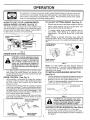
MULCHING
To start a cold engine, push primer five (5) times before
trying to start. Use a firm push. This step is not usually
necessary when starting an engine which has already
run for a few minutes.
o
Hold operator presence control bar down to the handle
and pull starter handle quickly. DO NOT allow starter
rope to snap back.
-
To STOP engine, release operator presence control
bar.
The special mulching blade will recut the grass clippings many times and reduce them in size so that as
they fall onto the lawn they will disperse into the grass
and not be noticed. Also, the mulched grass will
biodegrade quickly to provide nutrients for the lawn.
Always mulch with your highest engine (blade) speed
as this wilt provide the best recutting action of the
blades.
*
Avoid cutting you r lawn when it is wet. Wet grass tends
to form clumps and interferes with the mulching action.
The best time to mow your lawn is the early afternoon.
At this time the grass has dried and the newly cut area
will not be exposed to the direct sun.
For best results, adjust the lawn mower cutting height
so that the lawn mower cuts off only the top one-third
of the grass blades (See Fig. 7). tf the lawn is overgrown it will be necessary to raise the height of cut to
reduce pushing effort and to keep from overloading the
engine and leaving clumps of mulched grass. For
extremely heavy mulching, reduce your width of cut by
overlapping previously cut path and mow slowly.
TiPS
-
Under certain conditions, such as very tall grass, it may
be necessary to raise the height of cut to reduce
pushing effort and to keep from overloading the engine
and leaving clumps of grass clippings.
o
For extremely heavy cutting, reduce thewidth of cut by
overlapping previously cut path and mow slowly.
For better grass bagging and most cutting conditions,
the engine speed should be set in the fast position.
o
TIPS
•
NOTE: In cooler weather it may be necessary to repeat
priming steps. In warmer weather over priming may cause
flooding and engine will not start, if you do flood engine,
wait a few minutes before attempting to start and DO NOT
repeat priming steps.
MOWING
MOWING
IMPORTANT: FOR BEST PERFORMANCE, KEEP MOWER
HOUSING FREE OF BUILT-UP GRASS AND TRASH. SEE
"CLEANING" JN CUSTOMER RESPONSIBILITIES SECTION
OF THIS MANUAL.
TO START ENGINE
•
FILLER CAP
-
Certain types of grass and grass conditions may require that an area be mulched a second time to completely hide the clippings. When doing a second cut,
mow across or perpendicular to the first cut path.
=
Change your cutting pattern from week to week. Mow
north to south one weekthen change to east to west the
next week. This will help prevent matting and graining
of the lawn.
For side discharge lawn mowers, cutting in a counterclockwise direction, starting at the outside of the area
to be cut, spreads grass clippings more evenly and
puts less load on the engine. To keep clippings off of
walkways, flower beds, etc., make the first cuts in a
clockwise direction.
MAX 1/3
Pores in cloth grass catchers can become filled with dirt
and dust with use and catchers will collect less grass.
To prevent this, regularly hose catcher off with water
and let dry before using.
8
FIG. 7
CUSTOMER
......
HI
i
n
i
i
n
i
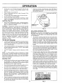
MAINTENANCE
SCHEDULE
FILL IN DATES
AS YOU COMPLETE
REGULAR SERVICE
M
O
W
E
R
SERWCE
Check for Loose Fasteners
CIeanllnspect Grass Catcher
(If Equipped)
Clean Lawn Mower
Clean Under Drive Cover
(Power-Propelled Mowers)
Check drive belt/pulleys
Power-Proj?elled Mowers)
Check/Sharpen/Replace Blade
Lubrication Chart
Clean Battery/Recharge
(Electric Staff Mowers)
more often when operating
DATES
_3
E Check Engine Oil Level
N
ine Oil
G Clean Air Filter
Inspect Muffler
N Clean or Replace Spark Plug
E Replace Air Filter Paper Cartridge
I - Change
m
_t_4'2
under a heav
load or in high ambient temperatures,
2 - Service more often when operating in dirty or dusty conditions.
3 - Replace blades more often when mowing in sandy soil,
4 - Charge 48 hours at end of season.
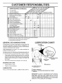
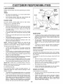
GENERAL
LUBRICATION
RECOMMENDATIONS
The warranty on this awn mower does not cover items that
have been subjected to operator abuse or negligence. To
receive full value from the warranty, operator must maintain
mower as instructed in this manual.
CHART
(_) WHEEL
ADJUSTER
Some adjustments will need to be made periodically to
properly maintain your unit.
All adjustments in the Service and Adjustments section of
this manual should be checked at least once each season.
Once a year, replace the spark plug, clean or replace
air filter element and check blade for wear. A new spark
plug and clean/new air filter element assures proper
air-fuel mixture and helps your engine run better and
last longer.
•
RiNG
BRACKET
(_ MULCHER
DOOR
Follow the maintenance schedule in this manual.
BEFORE
EACH
USE
,,
Check engine oil level.
-
Check for loose fasteners.
(_) ENGINE OIL
(_
HANDLE BRACKET
MOUNTING P_N
(_
SPRAY LUBRICANT
LUBRICATION
Keep unit well lubricated (See "LUBRICATION
CHART"),
(_) REFER TO CUSTOMER
SECTION,
RESPONS|BILITIES
"ENGINE"
1IMPORTANT: DO NOT OIL OR GREASE PLASTIC WHEEL
BEARINGS.
VISCOUS
LUBRICANTS
WILL ATTRACT
DUST AND DiRT THAT WILL SHORTEN THE LIFE OF
THE SELF LUBRICATING
BEARINGS. IFYOU FEEL THEY
MUST BE LUBRICATED,
USE ONLYA DRY, POWDERED
GRAPHITE
TYPE LUBRICANT
SPARINGLY.
9
CUSTOME
ILITIES
LAWN MOWER
BLADE
ADAPTER_
Always observe safety rules when performing any maintenance.
TIRES
KEY
•
Keep tires free of gasoline, oil, or insect control chemicals which can harm rubber.
=
Avoid stumps, stones, deep ruts, sharp objects and
other hazards that may cause tire damage.
BLADE
CRANKSHAFT
KEYWAY
BLADE
CARE
For best results, mower blade must be kept sharp.
Replace bent or damaged blades.
=
=
•
,
rKSHAFT
BL
BC
TO REMOVE BLADE (See Fig. 7)
Disconnect spark plug wire from spark plug and place
wire where it cannot come in contact with spark plug.
•
Turn lawn mower on its side. Make sure air filter and
carburetor are up.
HARDENED
WASHER
LOCK WASHER
TRAILING
EDGE
BLADE
ADAPTER
FIG. 7
Use a wood block between blade and mower housing
to prevent blade from turning when removing blade
bolt.
GEAR CASE
Protect your hands with gloves and/or wrap blade with
heavy cloth.
Remove blade bolt by turning counter-clockwise. Use
a 9/16" box or open-end wrench.
Remove blade and attaching hardware (bolt, lock
washer and hardened washer).
To keep your drive system working properly, the gear
case and area around the drive should be kept clean
and free of trash build-up. Clean under the drive cover
twice a season.
NOTE: Remove the blade adapter and check the key
inside hub of blade adapter. The key must be in good
condition to work properly. Replace adapter if damaged.
TO REPLACE BLADE (See Fig. 7)
Position the blade adapter on the engine crankshaft.
Be sure key in adapter and crankshaft keyway are
aligned.
•
Position blade on the blade adapter aligning the two (2)
holes in the blade with the raised lugs on the adapter.
Be sure the trailing edge of blade (opposite sharp
edge) is up toward the engine.
® Installthe blade bolt with the Iockwasher and hardened
washer into blade adapter and crankshaft.
•
Use block of wood between blade and lawn mower
housing and tighten the blade bolt, turning clockwise.
•
The recommended tightening torque is 35-40 ft. Ibs.
IMPORTANT: BLADE BOLT IS GRADE 8 HEAT TREATED.
•
The gear case is filled with lubricant to the proper level
at the factory. The only time the lubricant needs
attention is if service has been performed on the gear
case.
,
If lubricant is required, use only Texaco Starplex Premium Grease, part no. 750355. Do not substitute.
DRIVE
WHEELS
Check front drive wheels each time before you mow to be
sure they move freely.
The wheels not turning freely means trash, grass cuttings,
etc. are in the drive wheel area and must be cleaned to free
drive wheels.
If necessary to clean the drive wheels, check both front
wheels.
NOTE: We do not recommend sharpening blade- but if you
do, be sure the blade is balanced.
TO SHARPEN BLADE
-
Remove hubcaps, hairpin cotters and washers.
,
Remove wheels from wheel adjusters.
=
Remove any trash or grass cuttings from inside the
dust cover, pinion and/or drive wheel gear teeth.
•
Put wheels back in place.
•
If after cleaning, the drive wheels do not turn freely,
contact your nearest authorized service center.
Care should be taken to keep the blade balanced. An
unbalanced blade will cause eventual damage to lawn
mower or engine
GRASS
.
The blade can be sharpened with a file or on a grinding
wheel. Do not attempt to sharpen while on the mower.
,
The grass catcher may be hosed with water, but must
be dry when used.
•
To check blade balance, drive a nailinto a beam or wall.
Leave about one inch of the straight nail exposed.
Place center hole of blade over the head of the nail. If
blade is balanced, it should remain in a horizontal
position. If either end of the blade moves downward,
sharpen the heavy end until the blade is balanced.
=
Check your grass catcher often for damage or deterioration. Through normal use it will wear. If catcher
needs replacing, replace only with a manufacturer
approved replacement catcher. Give the lawn mower
model number when ordering.
CATCHER
(if purchased as an accessory)
10
CU
E
RESPONSIBILITIES
TO CHANGE AIR FILTER (See Fig. 9)
ENGINE
,
LUBRICATION
o
to the
Clean the inside of the cover and the collar to remove
any dirt accumulation.
Insert new filter into cover,
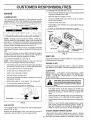
Use only high quality detergent oil rated with API service
classification SF, SG or SH. Select the oil's SAE viscosity
grade according to your expected operating temperature.
SAE VISCOSITY
Remove the air filter by turning counterclockwise
stop and pull away from collar.
Remove filter from inside of cover.
Put air filter cover and filter into collar aligning the tab
with the slot.
GRADES
Push in on cover and turn clockwise to tighten.
COLLAR
.3o
o
T
-20°
TEMPERATURE
-loo
_o"
D"
RANGE ANTICIPATED
2o°
BEFORE
3o_
40°
NEXT OIL CHANGE
NOTE: Although multi-viscosity otis (5W30, 10W30 etc.)
improve starting in cold weather, these multi-viscosity oils
wil! result in increased oil consumption when used above
32°F. Check your engine oii level more frequently to avoid
possible engine damage from running low on oil.
COUNTERCLOCKWISE
TO REMOVE
SLOT
Change the oil after every 25 hours of operation orat least
once a year if the lawn mower is not used for 25 hours in one
year.
AiR FILTER
Check the crankcase oil level before starting the engine
and after each five (5) hours of continuous use. Tighten oil
plug securely each time you check the oit level.
MUFFLER
Inspect and replace corroded muffler as it could create a
fire hazard and/or damage.
NOTE: Before tipping lawn mower to drain oil, drain fuel
tank by running engine until fuel tank is empty.
Disconnect spark plug wire from spark plug and place
wire where it cannot come in contact with spark plug.
Be sure lawn mower is on level surface.
=
Oil will drain more freety when warm.
Catch oil in a suitable container.
•
Remove bottom oil drain plug.
=
After oil has drained completely,
and tighten securely.
=
Refill engine with oil. Pour slowly.
SPARK
PLUG
Change your spark plug each year to make your engine
start easier and run better. Set spark plug gap at .030 inch.
CLEANING
IMPORTANT:
FOR BEST PERFORMANCE,
KEEP
MOWER HOUSING FREE OF BUILT-UP GRASS AND
TRASH. CLEAN THE UNDERSIDE OF YOUR MOWER
AFTER EACH USE.
replace oil drain plug
CAUTION: Disconnect spark plug wire
from spark plug and place wire where it
cannot come in contact with the spark
plug.
Do not over fill.
Fill to top of slot inside of filler hole.
Reconnect spark plug wire to spark plug.
o
Turn lawn mower on its side. Make sure air filter and
carburetor are up. Clean the underside of your lawn
mower by scraping to remove build-up of grass and
trash.
,
Clean engine often to keep trash from accumulating. A
clogged engine runs hotter and shortens engine life.
•
Keep finished surfaces and wheels free of all gasoline,
oit,etc.
\
CONTAINER
FIG. 8
AIR
TO TIGHTEN
FIG. 9
TO CHANGE ENGINE OiL (See Fig. 8)
=
_'URN CLOCKWISE
AIR FILTER COVER
We do not recommend using a garden hose to clean
lawn mower unless the electrical system, muffler, air
filter and carburetor are covered to keep water out.
Water in engine can result in shortened engine life.
FILTER
Your engine will not run properly and may be damaged by
using a dirty air filter.
CLEAN
Replace the air filter every year, more often if you mow in
very dusty, dirty conditions. Do not wash air filter.
1i
UNDER
DRIVE
COVER
Clean under drive cover at least twice a season. Scrape
underside of cover with putty knife or similar tool to remove
any buitd-up of trash or grass on underside of drive cover.
AN
CAUTION:
A
USTMENTS
BEFORE PERFORMING ANY SERVICE OR ADJUSTMENTS:
•
Release control bar.
=
Make sure the blade and all moving parts have completely stopped.
=
Disconnect spark plug wire from spark plug and place where it cannot come in contact with plug,
LAWN MOWER
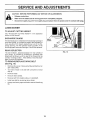
TO ADJUST
CUTTING
See "TO ADJUST CUTTING
section of this manual.
DISCHARGE
HEIGHT
HEIGHT" in the Operation
GUARD
DRIVE
_COVER
The discharge guard, attached to the discharge opening of
your lawn mower, is provided to prevent the possibility of
injury resulting from objects being thrown out of the discharge opening into the operator mowing position, tf the
discharge guard becomes damaged, it should be replaced.
BELT
PUSH
DOWN
REAR DEFLECTOR
The rear deflector, attached between the
your mower, is provided to minimize the
objects will be thrown out of the rear of the
operator mowing position. If the deflector
aged, it should be replaced.
TO REMOVE/REPLACE
DRIVE
FIG. 10
rear wheels of
possibility that
mower into the
becomes dam-
BELT
(See Fig. 10)
*
,
Remove drive cover. Remove belt by pushing down on
gear case pulley.
Turn lawn mower on its side with carburetor and fuel
cap up.
Remove blade.
,
Remove debris shield.
.
Remove belt from engine pulley on crankshaft.
,
,
Install new belt by reversing above steps.
,
Always use factory approved belt to assure fit and long
life.
12
SERVICE
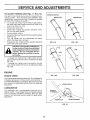
TO ADJUST
HANDLE
ADJUSTM
(See Figs. 11 Thru 13)
SHIPPING
Your lawn mower handle can be raised or lowered for your
mowing comfort.
Four (4) positions are available: high,
medium high, medium low and low. Handles are shipped
mounted in the medium low position.
•
To change from medium low to medium high position,
the upper and lower handle sections will have to be
turned over (See Fig. 11B).
Remove the cable clips.
=
Remove the controls and operator presence control
bar from the upper handle.
,
Remove hairpin cotters.
Disconnect the lower handle from the handle brackets
(See Fig. 13).
,
Turn the handle over and reassemble the hairpin
cotters that have been removed.
,
Reassemble the controls and the operator presence
control bar to the upper handle.
NTS
POSITION
MEDIUM LOW
MEDIUM HIGH
FIG. 11A
FiG. 11B
CAUTION: The operator presence con=
trol bar must pivot freely to permit blade/
brake engagement when control bar is
releasedo Do not overtighten the fas.
toners holding the controls to the upper handle.
,
-
To change from medium
upper handle section will
Fig. 12A).
To change from medium
lower handle section will
Fig. 12B).
LOW
low to high position only the
have to be turned over (See
low to low position, only the
have to be turned over (See
ENGINE
ENGINE
FIG. 12A
SPEED
Your engine speed has been factory set. Do not attempt to
increase engine speed or it may result in personal injury. If
you believe that engine is running too fast ortoo stow, take
your mower to an authorized service center for repair and
adjustment.
FIG. 12B
\
LOWER HANDLE
CARBURETOR
Your carburetor has a non-adjustable fixed main jet for
mixture control. If your engine does not operate properly
due to suspected carburetor problems, take your lawn
mower to an authorized service center for repair and/or
adjustment.
SQUEEZE
TO REMOVE
HAIRPIN
HANDLE
CLiP
FiG. 13
13
BRACKET
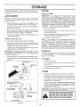
STORAGE
Immediately prepare your lawn mower for storage at the
end of the season or if the unit will not be used for 30 days
or more.
ENGINE
LAWN MOWER
IMPORTANT:
IT IS IMPORTANT
TO PREVENT
GUM
DEPOSITS
FROM FORMING
IN ESSENTIAL
FUEL
SYSTEM PARTS SUCH AS CARBURETOR,
FUEL FILTER,
FUEL HOSE, OR TANK DURING
STORAGE.
ALSO,
EXPERIENCE
INDICATES
THAT ALCOHOL
BLENDED
FUELS (CALLED GASOHOL
OR USING ETHANOL
OR
METHANOL)
CAN ATTRACT MOISTURE
WHICH LEADS
TO SEPARATION
AND FORMATION
OF ACIDS DURING
STORAGE.
ACIDIC
GAS CAN DAMAGE
THE FUEL
SYSTEM OF AN ENGINE WHILE IN STORAGE.
FUEL SYSTEM
When lawn mower is to be stored for a period of time, clean
it thoroughly/remove all dirt, grease, leaves, etc. Store in
a clean, dry area.
•
Clean entire lawn mower (See "CLEANING" in the
Customer Responsibilities section of this manual).
•
Lubricate as shown in the Customer Responsibilities
section of this manual.
Be sure that all nuts, bolts, screws, and pins are
securely fastened. Inspect moving parts for damage,
breakage and wear. Replace if necessary.
,
Touch up all rusted or chipped paint surfaces; sand
lightly before painting.
,
Drain the fuel tank.
•
Start the engine and let it run until the fuel lines and
carburetor are empty.
-
Never use engine or carburetor cleaner products in the
fuel tank or permanent damage may occur.
Use fresh fuel next season.
-
HANDLE
(See Fig. 14)
NOTE:
Fuel stabilizer is an acceptable alternative in
minimizing the formation of fuel gum deposits during storage. Add stabilizer to gasoline in fuel tank or storage
container. Always follow the mix ratio found on stabilizer
container, Run engine at least 10 minutes after adding
stabilizer to allow the stabilizer to reach the carburetor. DO
not drain the gas tank and carburetor if using fuel stabilizer.
You can fold your lawn mower handle for storage.
o
Squeeze the bottom ends of the tower handle toward
each other until the lower handle clears the handle
bracket, then move handle forward.
,
Loosen upper hand!e mounting bolts enough to allow
upper handle to be folded back.
IMPORTANT:
WHEN FOLDING THE HANDLE FOR
STORAGE OR TRANSPORTATION, BE SURE TO FOLD
THE HANDLE AS SHOWN OR YOU MAY DAMAGE THE
CONTROL CABLES.
,
ENGINE
Drain oil (with engine warm) and replace with clean engine
oil. (See "ENGINE"
in the Customer Responsibilities
section of this manual).
When setting up your handle from the storage position,
the lower handle will automatically lock into the mowing
position.
CYLINDER
LOWER HANDLE
MOUNTmNG
PIN
SQUEEZE
TO FOLD
j
OIL
\
•
Remove spark plug.
•
Pour one ounce (29 ml) of oil through spark plug h01e
into cylinder.
o
Pul! starter handle slowly a few times to distribute oil.
,
Replace with new spark plug.
OTHER
OPERATOR PRESENCE
CONTROLBAR
,
Do not store gasoline from one season to another.
,
Replace your gasoline can if your can starts to rust.
Rust and/or dirt in your gasoline witl cause problems.
-
tf possible, store your unit indoors and cover it to give
protection from dust and dirt.
®
Cover your unit with a suitable protective cover that
does not retain moisture. Do not use plastic. Plastic
cannot breathe which allows condensation to form and
wit! cause your unit to rust.
IMPORTANT: NEVER COVER MOWER WHILE ENGINE
AND EXHAUST AREAS ARE STILL WARM.
UPPER HANDLE
FOLDFORWARD
FORSTORAGE
FOLD BACKWARD
_ILA
MOWING
POSITION
LOWER HANDLE
FIG. 14
14
ing wb-.ere fume_ay
reach an open
fl_r
spakr., AHow the engine to
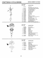
!
I
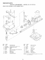
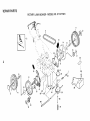
REPAIR PARTS
ROTARY
GEAR
CASE ASSEMBLY
LAWN
MOWER
PART NUMBER
-,-MODEL
NO. 917,37720!
702511
17
7\
15
19
14
13
!
KEY
NO.
PART
NO.
1
2
3
4
6
17490416
137055X004
137053
57072
48373
7
8
9
10
77881
137051
137074
57079
.......
DESCRIPTION
Tapping Screw 1/4-20 x 1-1/4
Engagement Bracket
Shifter
Sea!
Gear Case Halves Kit _Inciudes Key
Nos. 4, 5, and 7)
Bearing
Worm Shaft
Drive Shaft
Hardened Washer
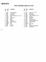
KEY
NO,
PART
NO,
!!
!2
13
14
15
16
t7
I8
19
t 3t 484
700343
86447
! 37050
75_'
75:
•
12000003
850848
81585X004
NOTE:
"15
DESCRIPTION
C _.._tch
Yoke
-4eticat Gear
Clutch Jaw
Grease
EoRhg
Hi.-Pro Key
Spring Bracket
All compor_ent dimensions
I inch = 25,4 mm
given in U.S. inches..
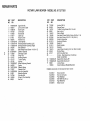
REPAIR
PARTS
ROTARY LAWN MOWER - MODEL NO, 917.377201
6
1
10
43
\
33
lO
o"}
.
23
24_
19
48
25
62
51
46
69
49
48
52
52
REPAIR PARTS
ROTARY LAWN MOWER - MODEL NO. 917.377201
KEY
NO,
1
3
5
6
7
8
9
10
12
18
19
22
23
24
25
27
28
29
33
35
36
38
39
40
41
42
43
44
PART
NO.
145646X479
156577
103672X
145793
131959
151517
51793
136376
151516X479
151667X479
151665X479
140540
750097
87584X004
151889
147286
154132
152124
150182
750085X007
146630
700331X004
701037
145935X004
62335
142748
150339
83923
DESCRIPTION
Upper Handle
Zone Control Cable
Rope Guide
Control Bar
Handle Bolt
Cable Clip
Hairpin Cotter
Handle Knob
Lower Handle
Handle Bracket Assembly (Left)
Handle Bracket Assembly (Right)
Rear Deflector
Hex Washer Head Screw #10-24 x 1/2
Deflector Bracket
Discharge Guard
Hinge Rod
Housing Bracket
Torsion Spring
Hubcap
Wheel Adjusting Bracket
Spacer
Selector Spring
Selector Knob
Axle Arm Assembly
BeJleville Washer
Shoulder Bolt
Wheel & Tire Assembly
Ftex Nut
KEY
NO.
PART
NO.
45
46
48
49
51
52
53
54
55
56
57
58
62
63
64
68
751592
85463
149741
63601
134612
150406
851084
850263
851074
152202
851514
752118
156516
85543
87677
......
69
70
71
--
153350X479
153282X479
63601
160904
DESCRIPTION
Locknut 3/8-16
Danger Decal
Thread Cutting Screw 5/16-18 x 3/4
Hex Locknut
Debris Shield
Hex Head Thread Rolling Screw 3/8-16 x 1-1/8
Hex Head Screw 3/8-24 x 1-3/8 (Grd. 8)
Helical Lockwasher
Hardened VVasher
Blade 22"
, Blade Adapter
Deflector
Lawn Mower Housing (Incl. Ref. #46, 59 & 60)
Engine Pulley
Hi-Pro Key #HP 505
Engine - (See Breakdown) Craftsman
Model 143.975502
Support Brkt Handle RH
Support Brkt Handle LH
Locknut Keps
Owner's Manual (English!Spanish)
Available accessories not included with lawn mower:
7J 33072
7"133623
7"133500
7_3_133300
71 33723
71 33316
Grass Catcher
Gas Can (2.5 gal.)
Fuel Stabilizer
SAE 30W Oil (20 oz.)
High Wheel Kit
Mower Cover
:{EPA|R PARTS
ROTARY LAWN MOWER - MODEL
NO. 917.37720!
11
/
13
15
/
10
/
28
15
-38
13
12
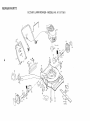
REPAIR PARTS
ROTARY LAWN MOWER - MQDEL NO. 917.377201
KEY
NO.
1
2
3
4
5
6
7
8
10
11
12
13
14
15
PART
NO.
146323
48385
63601
144929
146527
150495
145212
150182
88446
150340
12000058
137054
88080
88118
DESCRiPTiON
Control Cable Assembly
Control Head Kit
Locknut 1/4-20
Hex Washer Head Screw
V-Belt
Spring Retainer
Hex Nut
Hubcap
Nylon Bushing
Wheel & Tire Assembly
E-Ring
Pinion
Dust Cover
Felt Washer
#10-24 x 2-1/8
KEY
NO.
PART
NO.
16
18
25
26
28
31
32
33
35
36
37
38
40
4!
55
67725
701037
152903
143603
154990
132010
137052
48386
152018
702511
137090
STD541425
75192
152019
86012
DESCR_PTION
Washer 1/2 x 1-1/2 x .134
Selector Knob
Drive Cover Decal
Pan Head Tapping Screw #10-24
Drive Cover
Hex Flange Nut
Drive Pulley
Drive Control Cable Kit
Wheel Adjuster Assembly (Left)
Gear Case Assembly
Spring
• Locknut 1/4-20
Spring
Wheel Adjuster Assembly (Right)
Driveshaft Cover
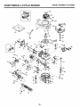
CRAFTSMAN
4=CYCLE ENGINE
MOOEL
NUMBER
143.97SS02
Oj
370K
390
287
261
260
4O0
130
126
120
223
241
<
238
245
250
20
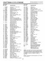
CRAFTSMAN
KEY PART
NO. NOo
1
2
6
7
12A
12B
!4
15
16
17
18
19
20
30
40
40
40
41
41
36478A
26727
33734
36557
36558
34695
28277
30589
32651
31335
651018
36281
32600
35996
36073
36074
36075
36070
36071
41
36072
42
42
42
43
45
46
48
50
52
69
70
72
73
75
80
81
82
83
86
89
90
92
93
100
101
103
110
119
120
125
125
36076
36077
36078
20381
30963B
32610A
27241
35992
29914
35261
34311D
30572
28833
27897
30574A
30590A
30591
30588A
650488
611004
611112
650815
650816
34443A
610118
651007
34961
36477
36476
36471
36472
126
126
130
135
150
151
169
172
174
178
182
184
29314B
29315C
6021A
35395
35991
31673
27234A
32755
30200
29752
6201
26756
4-CYCLE ENGINE
MODEL
NLR'4BER
!43°975502
KEY PART
NO. NO,
DESCRIPTION
185 36544
186 34337
189 650839
191 36559
195 610973
200 35727
202 36482
203 31342
204 650549
205 650777
207 34336
209 30200
215 32410
223 650451
224 34690A
238 650932
239 34338
241 35797
245 35066
250 35065
260 36915
261 30200
262 650831
275 36473
277 650988
285 35000A
287 650926
290 30705
292 26460
298 28763
300 36916
301 36246
305 35647
306 36832
307 35499
309 650562
310 35648
313 34080
370A 36261
370B 35167
370C 36861
370K 36695
380 632747
390 590694
400 36481
Cylinder (Incl. 2,7,20 & 125)
Dowel Pin
Breather Element
Breather Ass'y. (Inc!. 6 & 12A)
Breather Cover & Tube (Incl. 12B)
Breather Tube Elbow
Washer
Governor Rod (Incl. 14)
Governor Lever
Governor Lever Clamp
Screw, Torx T-15, 8-32 x 19/64"
Extension Spring
Oil Seal
Crankshaft
Piston, Pin & Ring Set (Std,)
Piston, Pin & Ring Set (.010" OS
Piston, Pin & Ring Set (.020" OS
Piston & Pin Ass'y. (Std.) (Incl. 43)
Piston & Pin Ass'y.
(.010" OS) (Incl. 43)
Piston & Pin Ass'y.
(.020" OS) (Incl. 43)
Ring Set (Std.)
Ring Set (.010" OS)
Ring Set (.020" OS)
Piston Pin Retaining Ring
Connecting Rod Ass'y. (Incl. 46)
Connecting Rod Bolt
Valve Lifter
Camshaft (MCR)
Oil Pump Ass'y.
Mounting Flange Gasket
Mounting Flange (Ind. 72 thru 83)
Oil Drain Plug (Incl. 73)
Drain Plug Gasket
Oil Seal
Governor Shaft
Washer
Governor Gear Ass'y. (Incl. 81)
Governor Spool
Screw, 1/4-20 x 1-1/4"
Flywheel Key
Flywheel
Belleville Washer
Flywheel Nut
Solid State Ignition
Spark Plug Cover
Screw, Torx T-15, 10-24 x 15/16"
Ground Wire
* Cylinder Head Gasket
Cylinder Head
Exhaust Valve (Std.) (Incl. 151)
Exhaust Valve
(1/32" OS) (Incl. 151)
Intake Valve (Std.) (Incl. 151)
Intake Valve (1/32" OS) (incl. 151)
Screw, 5/16-18 x 1-1/2"
Resistor Spark Plug (RJ19LM)
Valve Spring
Valve Spring Cap
* Valve Cover Gasket
Valve Cover
Screw, 10-24 x 9/16"
Nut & Lock Washer, 1/4-28
Screw, 1/4-28 x 7/8"
* Carburetor To Intake Pipe Gasket
416 36085
417 650760
900 -900 --
DESCRIPTION
Intake Pipe
Governor Link
Screw, 1/4-20 x 3/8"
S.E. Brake Bracket (Incl. 195)
Terminal
Control Bracket (Incl. 202 Thru 205)
Compression Spring
Compression Spring
Screw, 5-40 x 7/16"
Screw, 6-32 x 21/32"
Throttle Link
Screw, 10-24 x 9/16"
Control Knob
Screw, 1/4-20 x 1"
* Intake Pipe Gasket
Screw, 10-32 x 49/64"
* Air Cleaner Gasket
Air Cleaner Collar
Air Cleaner Filter
Air Cleaner Cover
Blower Housing
Screw, 10-24 x 9/16"
Screw, 1/4-20 x 1/2"
Muffler (Incl. 277)
Screw, 1/4-20 x 2-5/16"
Starter Cup
Screw, 8-32 x 21/64"
Fuel Line
Fuel Line Clamp
Screw, 10-32 x 35/64"
Fuel Tank (Incl. 292 & 301)
Fuel Cap
Oil Fill Tube
* "Q"-Ring
"O"-Ring
Screw, 10-32 x 1/2"
Dipstick
Spacer
Lubrication Decal
Control Decal
Primer Decal
Starter Decal
Carburetor (incl. !84)
Rewind Starter
Gasket Set
(Incl. Items Marked * in Notes)
Spark Arrestor Kit
(lncl. 417)(Optional)
Screw, 8-32 x 3/8" (Optional)
Replacement Engine NONE
Replacement S!B 750679A,
order from 71-999
RPM High 2900 to 3200
RPM Low 2450 to 2750
(NOTE: This engine could have been built with 590737
starter. Refer to the design of the rope pulley strength
ribs for part identification. Individual starter parts do not
interchange.) incl. Part #'s 26756 (1),27234A (1), 33735
(1), 36832 (1), 34338 (1), 34690A (1), 35261 (1),
36477 (1)
NOTE: All component dimensions given in U.S. inches
1 inch = 25.4 mm
21
CRAFTSMAN
4-CYCLE ENGINE
MODEL
NUMBER
143.975502
KEY PART
NO, NO,
q_"
"_>_-4 _ _._5_3_,,
-1
2
4
5
6
7
16
25
632747
631615
631767
631184
631183
632504
650506
631807
631867
Carburetor
(Incl. 184 of Engine Parts List)
Throttle Shaft & Lever Assembly
Throttle Return Spring
Dust Seal Washer
DustSeal (Throttle)
Throttle Shutter
Shutter Screw
Fuel Fitting
Float Bowl
-_/
÷....
27
28
29
631024
632019
631028
Float Shaft
Float Bowl"Q"
'_
30
31
35
631021
631022
36045
Inret Needle, Seat, & Clip (Incl. 31)
Spring Clip
Primer Bulb/Retainer Ring
36
37
632735
632547
MainRing,
Nozzle
Tube
"0"
Main
Nozzle Tube
40
44
48
632736
27110
631027
High Speed
Bowl Nut
Bowl
Nut Washer
Welch Plu Atmos hericVe
_7._Z__
_
._.o
O
""
_j
_-_
DESCRiPTiON
_!
,_'_..8
KEY PART
NO. NO.
--
- °
'-_
_ .....
E
_" _'_-'
(___
_-,
___
,,
t
DESCRIPTION
1
590694
590599A
Recoil Starter
Spring Pin (Inc!. 4)
3
4
2
5
6
7
8
590696
590601
590600
590697
590698
590699
590700
Retainer
Washer
Washer
Brake Spring
Starter Dog
Dog Spring
Pulley & Rewind Spring Ass'y.
11
590695
12
13
590535
590701
Starter Housing Ass'y.
(40 degree grommet)
Starter Rope ( 98" X 9/64" dia.)
Starter Handle
KEY PART
NO. NO.
22
Ring
-3
6
7
8
11
590737
590740
590616
590617
590618A
590687A
12
590535
13
14
590701
590741
DESCRIPTION
Rewind Starter
Retainer
Starter Dog
Dog Spring
Pulley & Rewind Spring Ass'y
Starter Housing Ass'y
(40 degree grommet)
Starter' Rope
(Length 98" x 9/64" dia.)
Starter Handle
Locking Tab
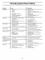
TROU
OOTING POINTS
PROBLEM
CAUSE
Does not start
1.
2.
3.
4.
Dirty air filter.
Out of fuel.
Stale fuel.
Waterin fuel.
1.
2.
3.
4.
5.
6.
7.
8.
g.
Spark plug wire is disconnected.
Bad spark plug.
Loose blade or broken blade adapter.
Control bar in released position
Control bar defective
5,
6.
7.
8.
9.
Clean!replace air filter=
Fil! fuel tank.
Drain tank and refill with fresh clean fuel.
Drain fuel tank and carburetorand refill tank with fresh
gasoline.
Connect wire to plug.
Replace spark plug.
Tighten blade bolt or replace blade adapter.
Depress control bar to handle.
Replace control bar.
1.
I.
Set in "Higher Cut" position.
2
3.
4,
5.
6
Rear of lawn mower housing/blade dragging
in heavy grass.
Cutting too much grass.
Dirty air filter.
Buildup of grass, leaves and trash under mower.
Too much oil in engine.
WaIking speed too fa_t.
2.
3.
4.
5.
6.
Set in "Higher Cut" position.
Clean/replace air filter.
Clean underside of mower housing.
Check oil level.
Cut at slower walking speed.
Poorcut-uneven
1,
2.
3,
4.
Worn, bent orloose blade.
Wheel heights uneven.
Low engine speed.
Buildup of grass, leaves, and trash under mower,
1.
2.
3.
4.
Replace blade. Tighten blade bolt.
Set all wheels at same height.
Set engine speed control in fast position.
Clean underside of mower housing.
Excessive
1,
2.
Worn, bent or loose blade.
Bent engine crankshaft.
1.
2.
Replace blade. Tighten blade bolt.
Contact an authorized service center/department.
1.
Engine flywheel brake is on when control bar is
released.
1.
2.
3.
4.
Bent engine crankshaft
Blade adapter broken.
Blade dragging in grass.
2.
3.
4.
Depress control bar to upper handle before
pulling starter rope.
Contact an authorized service center/department.
Replace blade adapter.
Move lawn mower to cut grass or to hard surface
to start engine.
Mowing)
1.
2.
Drive wheels not turning with drive control engaged.
Belt not driving.
1.
2.
Adjust or replace drive control cable, if broken.
Put bett on pulleys or replace belts if broken.
Grass catcher not filling
(If so equipped)
1.
2.
Cutting height too low,
Lift on blade worn off.
3.
4,
Catcher not venting air,
Low engine speed.
1,
2.
3.
4.
Raise cutting height.
Replace blade.
Clean grass catcher.
Set engine speed control in fast position,
1.
2.
1.
2.
3.
Grass is too high or wheel height is too low.
Rear of lawn mower housing/blade dragging
in grass.
Grass catcher too full.
4.
Handle height positlon not right for you.
Raise
Raise
setting
Empty
Adjust
Loss of power
vibration
Starter rope hard to pull
Loss of drive
(Self-Propelled
CORRECTION
_
Hard to push
23
3.
4.
cutting height.
rear of lawn mower housing one (1)
higher.
grass catcher.
handle height to suit.
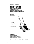
CRilFTSMI:IN®
OWNER'S
,IVlANUAL
5.5 HORSEPOWER
22" EZ MULCH
POWER PROPELLED
ROTARY LAWN MOWER
Each tawn mower has its own model number.
gine has its own model number.
MODEL NO.
917.377201
Each en-
The model number for your lawn mower will be found on a
decal attached to the rear of the lawn mower housing.
The model number for your engine wilt be found on the
blower housing of the engine.
All parts Iisted herein may be ordered from any Sears,
Roebuck and Co. Service Center/Department and most
Retail Stores.
iF YOU NEED
REPAIR SERVICE
OR PARTS:
WHEN ORDERING REPAIR PARTS, ALWAYS GIVE THE
FOLLOWING INFORMATION:
* PRODUCT - LAWN MOWER
o MODEL NUMBER - 917.377201
FOR REPAIR SERVICE, CALL
THIS TOLL FREE NUMBER:
! o800=4-REPAIR
(1-800=473o7247)
FOR REPLACEMENT PARTS
INFORMATION AND
ORDERING, CALL THIS
TOLL FREE NUMBER:
1-800=FONoPART
(1=800-366=7278)
,, ENGINE = CRAFTSMAN
- MODEL NO. 14.3,975502
', PART NUMBER
, PART DESCRIPTION
Your Sears merchandise has added value when you
consider Sears has service units nationwide staffed with
Sears trained technicians..,
professional technicians
specifically trained to insure that we meet our pledge to
you, we service what we sell.