1
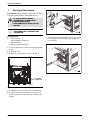
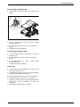
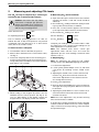
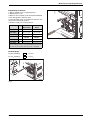
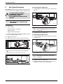
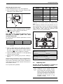
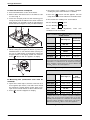
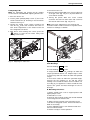
Installation Instructions
Gas Conversion Kit
For models: 250 SX, 250 SXO, GWH 2400 E, GWH 2400 EO, GWH 635 ES,
GWH 635 ESO, GWH 715ES, GWH 2700 ES, GWH 2400 ES, Evolution 500,
830ES, 940ES, 940ESO
Part. no 8 719 002 176
6 720 607 679 (2009/05) US
Warning: This kit shall be installed by a qualified
service agency in accordance with these
instructions and all applicable codes and
requirements of the authorities having jurisdiction.
Gas Type Conversion
1
Gas Type Conversion
For models: 250SX, 250SXO, GWH 635 ES, GWH
635 ESO, GWH 2400 E, GWH 2400 EO only
LP AND NG ARE EXTEMELY
FLAMMABLE SO TAKE EXTRA
PRECAUTIONS WHEN
PERFORMING ANY WORK TO THE
HEATER.
i
PROCEDURE MUST BE
PERFORMED BY A LICENSED GAS
TECHNICIAN.
Fig. 2
A. Preparation
B 7. Remove yellow painted # 40 Torx cover from the
front of the gas valve revealing a plastic #40 Torx
screw (Fig. 3).
B 1. Tools needed:
– flat and Phillips screwdrivers
– #40 Torx driver
– digital combustion analyzer
B 2. Turn power switch to off position and unplug water
heater.
B 3. Remove cover.
B 4. Remove control board access cover (Fig. 1).
Fig. 3
2 SCREWS
TO REMOVE
Fig. 1
B 5. Remove lower wire harness from control board.
B 6. Loosen yellow painted Philips screw and cover
should rotate down revealing a brass slotted screw
(Fig. 2).
2
6 720 607 679
Gas Type Conversion
B. Converting from LPG to NG
B 1. Add jumper to location JP6 on the control board
(Fig. 4).
6720607679-11.1AL
Fig. 4
B 2. Turn slotted brass screw 3.5 turns counter
clockwise (Fig. 2).
B 3. Turn #40 plastic torx screw 1 tooth clockwise
(Fig. 3).
B 4. Adjust CO2 (see chapter 2).
C. Converting from NG to LPG
B 1. remove jumper from location JP6 on the control
board (Fig. 4).
B 2. Turn slotted brass screw 3.5 turns clockwise
(Fig. 2).
B 3. Turn #40 plastic torx screw 1 tooth counter
clockwise (Fig. 3).
B 4. Adjust CO2 (see chapter 2).
D. Clean up
B 1. Reinstall yellow painted #40 Torx cover on the
front of gas valve (Fig. 3).
B 2. Rotate brass slotted screw cover up and tighten
yellow painted Philips screw (Fig. 2).
B 3. Reinstall lower wire harness onto control board.
B 4. Reinstall control board access cover (Fig. 1).
B 5. Apply conversion sticker to right side panel above
rating plate. Ensure information is filled out
accurately.
B 6. Reinstall cover and return to service.
6 720 607 679
3
Measuring and adjusting CO2 levels
2
Measuring and adjusting CO2 levels
The CO2 can only be adjusted by a certified gas
technician with a calibrated CO2 analyzer.
Caution: One factor that may affect
CO2 levels is improper gas pressure.
Please see Chapter 2.12 of manual for
the procedure to measure gas pressure
and record your findings below:
Static Gas Pressure:
" WC
P1 Operating Pressure:
" WC
The P1 minimum operating pressure is 5" WC for
Natural Gas and 11"WC for Propane. Do not proceed
in adjusting CO2 until pressure is at or above these
levels, but not to exceed 14” WC.
A. Once Pressure is adequate
B Turn ON/OFF switch to the OFF (O) position.
B Remove brass flat head screw on the exhaust collar,
see Fig. 5.
B Insert CO2 analyzer probe into the measuring port.
Avoid air gaps between probe and measuring port.
The tip of the probe should be in the center of the flue
pipe (approx 1.5" inserted).
B. Measuring CO2 (Cover Installed):
B Open hot water taps to achieve a flow rate of at least
4 gallons per minute. (1 tub and 2 sinks should be
sufficient).
B Record the CO2 reading in P2 below. (Analyzer reading may take several minutes to stabilize).
B Press the ‘+’ button until P1 appears. Unit will ramp
up to high fire and the water flow should increase.
B Record the CO2 reading in P1 below.
P2 CO2 Reading:
% CO2
P1 CO2 Reading:
% CO2
Compare your readings to those found in table 1 under
the “With Front Cover” column. If CO2 readings are off
make adjustments as outlined below.
Note: The “Without Front Cover” column give
approximate values with the cover off to ease the
adjustment process. Final readings should be taken
with the cover on.
C. Adjusting CO2:
Note: P1 adjustment will change the P2 reading.
Confirm the P1 value BEFORE adjusting the P2 level.
1. P1 CO2 level adjustment:
B Loosen yellow painted Philips screw (1) and rotate
cover down (2) revealing a brass slotted screw.
Fig. 7.
B Adjusting the slotted screw counter clockwise will
raise P1 CO2 levels and clockwise will lower P1
CO2 levels. Adjustments to the slotted screw will
also change P2 CO2 levels.
2. P2 CO2 level adjustment:
B Remove yellow painted #40 Torx cover from the front
of the gas valve. (Fig. 8) A plastic #40 Torx screw will
be revealed.
Fig. 5
B While holding in the Program (P) button, turn the
ON/OFF switch to ON (I) position (see Fig. 6). As
soon as ‘188’ flashes on the display, release the
Program button. The display should now read P2.
B Adjusting the plastic #40 Torx screw counter clockwise will lower P2 CO2 levels and clockwise will
raise P2 CO2 levels.
Note: This screw adjustment is very sensitive and may
take several minutes to stabilize.
3. Verify both P1 and P2 are within the ranges specified
in table 1 under the “With Front Cover” column. Repeat
steps 1 and 2 as necesssary until CO2 values are within
the specified ranges.
Fig. 6
4
6 720 607 679
Measuring and adjusting CO2 levels
D. Returning to Service:
1. Return slotted cover to original position.
2. Reinstall Torx cover.
3. Remove CO2 analyzer probe and reinstall flathead
screw with gasket in exhaust collar.
4. Turn ON/OFF switch to the OFF (O) position and
then back to the ON (I) position.
5. Heater is ready for normal operation.
Without
Front Cover
With Front
Cover
Nat. Gas
Nat. Gas
max. input
P1
9.1 ± 0.1 %
9.7 ± 0.1 %
min. input
P2
9.4 ± 0.1 %
9.7 ± 0.1 %
LP Gas
LP Gas
max. input
P1
10.1 ± 0.1 %
10.7 ± 0.1 %
min. input
P2
10.4 ± 0.1 %
10.7 ± 0.1 %
Fig. 8
* Final reading must be confirmed with the front cover
on, CO2 levels increase when the cover is installed.
Table 1
Final Readings
P2 CO2 Reading:
% CO2
P1 CO2 Reading:
% CO2
Fig. 7
6 720 607 679
5
Gas Type Conversion
3
Gas Type Conversion
B. Converting from LPG to NG
For models: GWH 2400 ES, GWH 2700 ES, GWH
715 ES, Evolution 500, 830ES, 940ES, 940ESO only.
B 1. Add jumper to location JP6 on the control board
(Fig. 11).
LP AND NG ARE EXTREMELY
FLAMMABLE. TAKE EXTRA
PRECAUTIONS WHEN
PERFORMING ANY WORK TO THE
HEATER.
i
PROCEDURE MUST BE
PERFORMED BY A LICENSED GAS
TECHNICIAN.
A. Preparation
6720607679-06.1AL
Fig. 11 LPG to NG
B 1. Tools needed:
i
– Flat and Phillips screwdrivers
– #40 Torx driver
– Digital combustion analyzer
P1 fan speed is automatically ajusted
when is added the jumper, to verify value
see Table 3.
B 2. Adjust CO2 (see chapter 3.1).
B 2. Shut off gas supply at installer supplied shutoff
valve and unplug the power cord.
C. Converting from NG to LPG
B 3. Remove front cover.
B 1. Remove jumper from location JP6 on the control
board (Fig. 12).
B 4. Remove the three screws from the control unit.
Fig. 9
B Pull control unit out and rotate to reveal the back
side.
B Remove the small cover of the control unit.
6720607679-07.1AL
Fig. 12 NG to LPG
i
P1 fan speed is automatically adjusted
when jumper is removed, to verify value
see Table 3.
B 2. Adjust CO2 (see chapter 3.1).
B 3. Replace small cover on control unit's back and
reinstall control unit in the water heater.
6720607679-08.1AL
Fig. 10
6
6 720 607 679
Gas Type Conversion
Operating Gas Pressure Test
Model
B Press ON/OFF button to turn off the appliance.
B Press and hold "Program" (P) button and press ON/
OFF button to turn appliance ON.
Fig. 13
B As soon as '188' is displayed, release "Program"
, button and the display should read P2.
B Press
NG
LPG
830ES
42
40
940ES
48
46
940ESO
48
46
GWH 715 ES
48
46
Evolution 500
48
46
GWH 2700 ES
48
46
GWH 2400 ES
42
40
Table 3 Fan speed values for P1 (factory default)
Lowering P1 fan speed reduces the maximum BTU
input.
As a temporary measure if the gas pressure in P1 is
below specification, lower P1 fan speed incrementally
until minimum inlet gas pressure reaches specified
range (Table 2). After raising gas pressure, reset
appliance to P1 factory default setting.
until P1 appears.
Note: While in this mode the appliance will run
constantly at maximum power and allow
maximum water flow.
For inlet gas pressure minimum specification, use the
following table:
Gas type
NG
LPG
P1 pressure
3.5” WC
8” WC
Table 2 Minimum inlet gas pressure under full
operation
B Turn on a high volume of hot water flow (at least 6
gpm) and heater will ignite. If heater display reverts to
P2, open more hot water fixtures to allow sufficient
flow. Press "
" until P1 reappears on display.
Fig. 14 Gas pressure test port (left tapping)
Static Gas Pressure Reading
B Operate all other gas appliances on same gas piping
system at maximum output.
enter here: ______________ " WC Date: ___________
B Record lowest operating gas pressure reading in
table 4.
Operating Gas Pressure Reading
Gas pressures lower than 3.5" W.C. for Natural Gas or
8" W.C. for LPG will result in insufficient degree rise to
the hot water, reduced hot water volume, possible error
codes and must be corrected. See Gas Connections in
the installation manual.
P1 fan speed (Factory default):
enter here: ______________" WC Date: ___________
Table 4
3.1
The CO2 can only be adjusted by a certified gas
technician with a calibrated CO2 analyzer.
i
6 720 607 679
Adjusting CO2
CO2 adjustment is required in
installations above 2,000ft. (610m),
and in Natural Gas installations where
energy content is less than 900 BTU/
cu ft, and in installations with repeated
unresolved EA and EC errors (ref. to
"Problem solving" section of the
installation manual.).
7
Gas Type Conversion
A. Once Gas Pressure is adequate
B Press ON/OFF button to turn off the heater.
B Record the CO2 reading in P1 below. (Analyzer
reading may take several minutes to stabilize).
B Remove brass flat head screw on the exhaust collar
as seen in Fig. 5.
B Press the ‘
’ button until P2 appears. Unit will
ramp down to low fire and the flow should decrease.
B Insert CO2 analyzer probe into the measuring port.
The tip of the probe should be in the center of the flue
pipe (approx 1.5" inserted). Avoid air gaps between
probe and measuring port as they can alter readings.
B Record the CO2 reading in P1 and P2 below.
P2 CO2 Reading:
% CO2
P1 CO2 Reading:
% CO2
Note: When making adjustments,
combustion cover is installed.
make
sure
Values for GWH 715 ES, GWH 2700 ES, Evolution 500,
940ES, 940ESO
CO2 range (%)
Max. CO level
(measured)
Nat. Gas
Fig. 15 Measuring port
B While holding the Program (P) button in, press the
ON/OFF button to turn ON the heater (see Fig. 6).
As soon as ‘188’ flashes on the display, release the
Program button. The display should now read P2.
Press ‘
’ button until “P1” appears on display.
max. input
P1
7.5 % - 8.1 %
< 250 ppm
min. input
P2
2.3 % - 2.6 %
< 60 ppm
LP Gas
max. input
P1
8.7 % - 9.3 %
< 250 ppm
min. input
P2
2.7 % - 3.0 %
< 60 ppm
* Values above are for climate controlled conditions. Inputs
such as gas pressure, heating value of the gas, humidity and
temperature of combustion air all impact CO and CO2
values. Changes in these inputs can result in different CO
and CO2 values on the same appliance.
Table 5
CO2 & CO target numbers
Values for GWH 2400 ES, 830ES
CO2 range (%)
Fig. 16
B. Measuring CO2 (combustion cover must be
installed):
Max. CO
level
(measured)
Nat. Gas
B Open all hot water taps to achieve a flow rate of at
least 6 gallons per minute. (1 tub and 2 sinks should
be sufficient). If heater display reverts back to P2,
open more hot water fixtures to allow sufficient flow.
max. input
P1
7.2 % - 7.8 %
< 250 ppm
min. input
P2
2.3 % - 2.6 %
< 60 ppm
B Press ‘
max. input
P1
8.3 % - 8.9 %
< 250 ppm
min. input
P2
2.6 % - 2.9 %
< 60 ppm
’ until P1 reappears on display.
LP Gas
* Values above are for climate controlled conditions.
Inputs such as gas pressure, heating value of the gas,
humidity and temperature of combustion air all impact CO
and CO2 values. Changes in these inputs can result in
different CO and CO2 values on the same appliance.
Table 6
8
CO2 & CO target numbers
6 720 607 679
Gas Type Conversion
C. Adjusting CO2:
2. If P2 CO2 level is off:
Note: P1 adjustment will change the P2 reading.
Confirm the P1 value BEFORE adjusting the P2 level.
B Remove yellow painted #40 Torx cover from the front
of the gas valve. (Fig. 18, pos.1) A plastic #40 Torx
screw will be revealed.
1. If P1 CO2 level is off:
B Loosen yellow painted philips screw (1) and cover
should rotate down (2) revealing a recessed brass
slotted screw. Fig. 17.
B Turning the slotted screw counter clockwise will
raise P1 CO2 levels and clockwise will lower P1
CO2 levels. Adjustments to the slotted screw will
also change P2 CO2 levels.
B Turning the plastic #40 Torx screw counter
clockwise will lower P2 CO2 levels and clockwise
will raise P2 CO2 levels. (Fig. 18, pos. 2).
Note: This screw adjustment is very sensitive and
should be made in small increments. It may take several
minutes for readings to stabilize.
B After the P1 CO2 readings are correct, press the
‘
’ button to enter the P2 mode. Verify CO2
readings in P2 mode.
1
1
3
2
6720607679-09.1AL
2
6720607679-10.1AL
Fig. 17 Adjusting P1 CO2 level
Fig. 18 Adjusting P2 CO2 level
Final Readings
P2 CO2 Reading:
% CO2
P1 CO2 Reading:
% CO2
3. Verify both P1 and P2 CO2 readings are within the
ranges specified in table 5 or 6. Repeat steps 1 and 2
as necesssary until CO2 values are within the specified
ranges.
4. Once CO2 values are within the specified ranges,
measure the CO readings on P1 and P2. These
readings can’t exceed the values shown in table 5 or 6
according to your appliance. If values exceed this limit,
inspect vent system and heat exchanger fin coils for
blockage.
D. Returning to Service:
1. Return slotted screw cover to original position and
tighten philips screw.
2. Reinstall Torx cover.
3. Remove CO2 analyzer probe and reinstall flathead
screw with gasket in exhaust collar.
4. Apply conversion sticker to the right side of front
cover above rating plate sticker. Ensure information is
filled out accurately.
5. Press ON/OFF button to turn OFF the heater and
then turn ON the heater.
6. Heater is ready for normal operation.
6 720 607 679
9
Gas Type Conversion
10
6 720 607 679
Gas Type Conversion
6 720 607 679
11
Replacement Parts available from:
BOSCH THERMOTECHNOLOGY
CORP.
50 Wentworth Avenue
Londonderry, NH 03053
Tel. 866-330-2730
www.boschpro.com
Recycled paper
Bosch Termotecnologia SA
Estrada de Cacia
3800 - 533 Cacia - PORTUGAL
© 2010 Bosch Thermotechnology Corp.,
Londonderry, NH