1
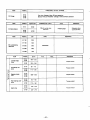
ROBIN AMERICA, INC.
ROBIN TO WISCONSIN ROBIN
ENGINE MODEL CROSS REFERENCE LIST
WISCONSIN ROBIN
ROBIN
0
SIDE VALVE
W 1-080
W1-145
W1-145V
W1-185
W1-185V
W1-230
W 1-280
W 1-340
W 1-390
Wl-45OV
EY21W
EY44W
EY18-3W
EY25W
EY27W
EY08
EY15
EY 15V
EY20
EY2OV
EY23
EY28
EY3 5
EY40 EY45V
EY2 1
EY44
EY 18-3
EY25
EY27
OVERHEAD VALVE
WO1-115
wo1-120
WO1-150
WO1-170
wo1-210
WOl-250
WO 1-300
WO1-300V
WO1-340
WO 1-340V
WO 1-43
OV
EH11
EH12
EH15
EH17
EH21
EH25
EH30
EH30V
EH34
EH34V
EH43V
0
TWO CYCLE
WT1-125V
EC13V
DIESEL
DY23
DY27
DY30
DY35
DY4 1
WRD 1-230
WRD 1-270
-1-300
WRD1-350
WRD1-410
0
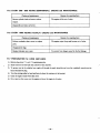
CONTENTS
.
2.
1 SPECIFICATIONS
1
...........................................
MaximumOutput . . . . . . . . . . . . . . . . . . . . . . . . . . . . . . . . . . . . . . .
Continuous
Rated Output . . . . . . . . . . . . . . . . . . . . . . . . . . . . . . . . .
Maximum
Torque . . . . . . . . . . . . . . . . . . . . . . . . . . . . . . . . . . . . . . .
3. FEATURES
.
...........................................
PERFORMANCE
2- 1
2-2
2-3
4
Page
Title
Section
...............................................
...............
Cylinder. Crankcase . . . . . . . . . . . . . . . . . . . . . . . . . . . . . . . . . . . . .
Main Bearing Cover . . . . . . . . . . . . . . . . . . . . . . . . . . . . . . . . . . . . . .
Crankshaft . . . . . . . . . . . . . . . . . . . . . . . . . . . . . . . . . . . . . . . . . . .
ConnectingRodandPiston
................................
Camshaft . . . . . . . . . . . . . . . . . . . . . . . . . . . . . . . . . . . . . . . . . . . .
3
GENERAL DESCRIPTION of ENGINE CONSTRUCTION
4
4-1
4-2
4-3
4-4
4-5
4-6
4-7
4-8
4-9
4-10
4 - 11
4-12
4- 13
4-14
4
4
5
5
6
6
7
7
Valve Arrangement . . . . . . . . . . . . . . . . . . . . . . . . . . . . . . . . . . . . . .
CylinderHead . . . . . . . . . . . . . . . . . . . . . . . . . . . . . . . . . . . . . . . . .
Governor . . . . . . . . . . . . . . . . . . . . . . . . . . . . . . . . . . . . . . . . . . . .
Cooling . . . . . . . . . . . . . . . . . . . . . . . . . . . . . . . . . . . . . . . . . . . . . .
Lubrication . . . . . . . . . . . . . . . . . . . . . . . . . . . . . . . . . . . . . . . . . . .
Ignition . . . . . . . . . . . . . . . . . . . . . . . . . . . . . . . . . . . . . . . . . . . . .
Carburetor . . . . . . . . . . . . . . . . . . . . . . . . . . . . . . . . . . . . . . . . . . .
Air Cleaner . . . . . . . . . . . . . . . . . . . . . . . . . . . . . . . . . . . . . . . . . . .
Sectional View of Engine . . . . . . . . . . . . . . . . . . . . . . . . . . . . . . . . . .
8
8
9
9
10
5. DISASSEMBLY and REASSEMBLY . . . . . . . . . . . . . . . . . . . . . . . . . . . . . . .
18
PreparationandSuggestion . . . . . . . . . . . . . . . . . . . . . . . . . . . . . . . . .
Special Tools . . . . . . . . . . . . . . . . . . . . . . . . . . . . . . . . . . . . . . . . . .
Haw To Disassemble . . . . . . . . . . . . . . . . . . . . . . . . . . . . . . . . . . . . .
How To Reassemble . . . . . . . . . . . . . . . . . . . . . . . . . . . . . . . . . . . . .
18
18
20
27
5-1
5-2
5-3
5-4
6. MAGNETO
6-1
6-2
...............................................
Magneto . . . . . . . . . . . . . . . . . . . . . . . . . . . . . . . . . . . . . . . . . . . . .
Breaker PointAdjustment
.................................
6-3 Timing Adjustment for EY15. EY20 Point Type Ignition System . . . . . . . .
6-4
6-5
Magneto Trouble Shooting . . . . . . . . . . . . . . . . . . . . . . . . . . . . . . . . .
Solid State Ignition . . . . . . . . . . . . . . . . . . . . . . . . . . . . . . . . . . . . . .
7 . GOVERNORADJUSTMENT
37
37
37
38
39
39
...................................
40
............................................
OperationandConstruation
................................
Disassembly
and
Reassembly
...............................
42
8. CARBURETOR
8-1
8-2
8
9. BREAK-IN OPERATION Of REASSEMBLED ENGINE
................
42
43
45
Section
pese
Title
.
10 ROBIN SOLID STATE IGNITION ENGINE
(T.I.C. and P.I.T.)
............
10-1 Features . . . . . . . . . . . . . . . . . . . . . . . . . . . . . . . . . . . . . . . . . . . . .
10-2 Basic Theory of T . I.C. . . . . . . . . . . . . . . . . . . . . . . . . . . . . . . . . . . .
10-3 Basic Theory of P.I.T.
.
11 TROUBLESHOOTING
11 .1
11 - 2
11- 3
11 - 4
11-5
11 -6
.
.
14
50
.............................................
50
Installing
Ventilation . . . . . . . . . . . . . . . . . . . . . . . . . . . . . . . . . . . . . . . . . . .
Exhaust Gas Discharge . . . . . . . . . . . . . . . . . . . . . . . . . . . . . . . . . . . .
PowerTransmission to Driven Machines . . . . . . . . . . . . . . . . . . . . . . . .
Wiring . . . . . . . . . . . . . . . . . . . . . . . . . . . . . . . . . . . . . . . . . . . . . .
..........................
Specifications . . . . . . . . . . . . . . . . . . . . . . . . . . . . . . . . . . . . . . . . .
Operation . . . . . . . . . . . . . . . . . . . . . . . . . . . . . . . . . . . . . . . . . . . .
(Option)
RECOILSTARTERDISASSEMBLY
14-1
14-2
14-3
14-4
................
..............................
and REASSEMBLY
50
50
50
51
53
53
53
54
How To Disassemble (Type D)
How To Reassemble (Type D) . . . . . . . . . . . . . . . . . . . . . . . . . . . . . . .
Check Items after Reassembly
How ToDo in Such Cases! . . . . . . . . . . . . . . . . . . . . . . . . . . . . . . . . .
54
55
57
57
...................................
58
...............................
.
15 CHECKS and CORRECTIONS
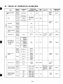
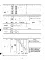
16. TABLE of CORRECTIONSTANDARDS
.
...........................
59
.................................
Maintenance . . . . . . . . . . . . . . . . . . . . . . . . . . . . . .
65
17 MAINTENANCE and STORING
17-1
17-2
17-3
17-4
17-5
17-6
17- 7
47
48
48
48
49
49
............................................
13. ELECTRICSTARTINGMOTOR
13- 1
13-2
46
46
46
...................................
. . . . . . . . . . . . . . . . . . . . . . . . . . . . . . . . . . . . . . . 47
StartingDifficulties . . . . . . . . . . . . . . . . . . . . . . . . . . . . . . . . . . . . . .
EngineMisfires . . . . . . . . . . . . . . . . . . . . . . . . . . . . . . . . . . . . . . . . .
EngineStops . . . . . . . . . . . . . . . . . . . . . . . . . . . . . . . . . . . . . . . . . .
Engine
Overheats
.......................................
Engine
Knocks . . . . . . . . . . . . . . . . . . . . . . . . . . . . . . . . . . . . . . . . .
EngineBackfires through Carburetor . . . . . . . . . . . . . . . . . . . . . . . . . .
12 INSTALLATION
12-1
12-2
12-3
12-4
12-5
46
Daily Checksand
Every 20 Hours ChecksandMaintenance
.......................
Every 50 Hours ChecksandMaintenance
Every 100 200 Hours (Monthly) Checks and Maintenance . . . . . . . . . . .
Every 500 600 Hours (Semiannual) Checksand Maintenance . . . . . . . . .
Every 1000 Hours (Yearly) ChecksandMaintenance . . . . . . . . . . . . . . . .
Preparation for Long Abeyance . . . . . . . . . . . . . . . . . . . . . . . . . . . . . .
--
.......................
65
65
65
65
66
66
66
.
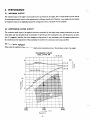
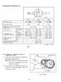
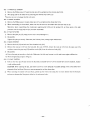
2. PERFORMANCE
2-1 MAXIMUM OUTPUT
The maximum ouput of anengine is such standard power asdeveloped by the engine, after its initial break
in period with all
the moving parts properly worn in, when operating with a fully open
throttle valve. Therefore, a new engine may not develop
the maximum outputin the beginning because the moving parts are not in a properly worn-incondition.
2-2 CONTINUOUS RATED OUTPUT
The continuous rated output of an engine is sudrpower as developed by that engine when running continuously at an optimum speed, and most favorable from the viewpoint of engine life and fuel consumption ratio, with the governor in operation. It is suggested, therefore, that when designing a driving system for any mechanism, with this engine as prime mover,
the continuous power requirement
of that mechanism be kept below the continuous rated outputspecified.
23 MAXIMUM TORQUE
These mean the maximum torqueof the output shaft and fuel consumption ratio at the maximum output of an engine.
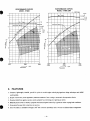
PERFORMANCE CURVES
MODEL EY15D, 15B
1 for B type
(
kg-m
4
-7
Ma;. Torque
~
0.6
I
I
0.7
HP
t i i
2000
(1000)
I \
I
I
3000
(1 500)
Revolution
-2-
I
I
r.p.m.
I
I
I
4000
(20001
PERFORMANCE CURVES
MODEL EY28D, 288
PERFORMANCE CURVES
MODEL EYZOD
I
)
for B t v m
5
1 .o
Max. Toraue
4
3
HP
.L
B
w
r
2
2
1
2000
3000
2000
3000
4000
( 1 000)
( 15001
I20001
4000
r.p.m.
r.p.rn.
Revolution
Revolution
3. FEATURES
1. Compact, lightweight, durable, powerful 4-cycle air-cooled engine embodying ingenious design
t e c h q u e s and skilful
workmanship.
2. Simple construction, smart appearance, maximumeasiness of start owing to automatic decompression device
3 . Pointless Solid State ignition system is newly adopted for preventing poor igniting as option.
4. Reliable prime mover for variety of purposes with smooth speed control by agovernor under varying load conditions.
5 . Economical because fuel consumption is very low.
6 . Great ve:satility in installation through a 360" belt extension possibihty and a two-side oil fill and drain arrangement.
-3-
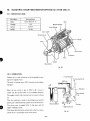
4. GENERALDESCRIPTION
of ENGINECONSTRUCTION
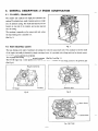
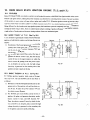
4-1 CYLINDER, CRANKCASE
The cylinder and crankcase are
single piece aluminum die
casting. The c y h d e r liner, made of special castiron, is built
into the alminum casting. The intake and exhaust ports are
located on one
side of the cyhder, and are also inserted
into the casting.
The crankcase is separable on the output shaft side, where
the main bearing cover is attached to it.
(See Fig. 1 .)
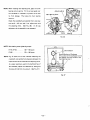
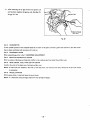
4-2 MAIN BEARING COVER
Fig. 1
The main bearing cover made of aluminum die casting is built onto the output shaftside of the crankcase so that the inside
of the engine can readily be checked by simply removing the cover. It is provided with a flange and boss for directly mounting machmes, such as generators and pumps.
Two oil gauges also serving as oil filler caps can be mounted. (See Fig. 2 and Fig. 3.)
The EY 15B engine has 2 chain guides and a built-in shelter plate to prevent oil from being stirred by the governor gear
(See F i g . 4.)
Ring for Centering
/
I
Oil Gauge
Governor Gear
Oil Gauge
Fig. 3
Fig. 2
Chain Guide
- Shelter Plate
1
Fig. 4 (E Y 15B)
-4-
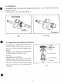
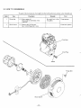
4-3 CRANKSHAFT
The crankshaft is forged of carbon steel, and the crankpin is induction-hardened. It has a crank
gear premred-fitted on the
output end. (See Fig. 5 . ) .
"he EY 15B type has a built-in drive sprocket. (See Fig. 6 . )
Induction Hardening
(Portion of Crankpin)
Crank Gear
(Pressure-Fit)
Drive Sprocket
-
Fig. 6 (E Y 158)
Fig. 5
4-4 CONNECTING ROD, PISTON and PISTON RING
The connecting rod is forged of aluminum alloy, which itself serves as bearings at both the large and small ends. The
large end has a built-in oil scraper for splashing the lubricating oil.
The piston is cast of aluminum alloy, and has
grooves for
Connecting Rod
receiving two compression rings and one oil ring.
(See Fig. 7.)
PISTON RINGS for EY28 ENGINE
Thispiston
ringsare
made of specialcastiron
Rod Lock Washer
and the
Oil Scraper
shape of the top ring is barrel face, that of second ring is
taper under cut; and the oil ring has cutter expander.These
rings are very mucheffectivefordecreasingengine
1
oil
Fig. 7
consumption.
-5-
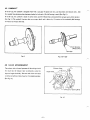
4-5 CAMSHAFT
In the D type, the camshaft is integrally built with a cam gear of special cast iron, and has intake and exhaust cams. Also
the camshaft has aluminum plain bearings attached to bothends. (No ball bearing is used.) (See Fig. 8.)
In the B type, the camshaft is made of carbon steel, and EYlSB type has a pressured-fitted cam gear and a driven sproket.
(See Fig. 9.) The camshaft functions also as an output shaft, and is driven by 1/2 rotation of the crankshaft, Ball bearings
are used in the output shaft side.
Driven Sprocket
(Pressure-Fit)
Cam Gear
J
Fig. 8
Fig. 9 (E Y 156)
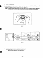
4-6 VALVE ARRANGEMENT
I
The exhaust vahe is located upstream of the coolingair with
the result thattheexhaust
Exhaust Valve
valve is intensiveiy cooled for
improved engine durability. The inner side of the valve head
is reinforced with hard alloy fused to it for added durability.
(See Fig. 10.)
Direction of Cooling Wind
Fig. 70
-6-
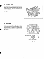
4-7 CYLINDER HEAD
The cylinder head is an aluminum die casting, and forms a
Ricardo type combustion.chamber with amplearea for high
combustioneffeciency.Thesparkplug
is tiltedforeasy
mounting of the fuel tank.
(See Fig. 11.1
Fig. 1 1
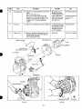
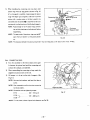
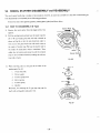
4-8 GOVERNOR
The governor is a centrifugal flyweight type which permits
constant operation at the selected speed against load variations. Governor gear is installed on the bearing cover without fail, and it engages with the cam gear afterreassembling.
(See Fig. 12.)
/
Main Bearing Cover
1
Governor Sleeve
Governor Gear Complete
Fig. 12
-7-
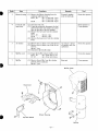
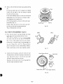
4-9 COOLING
The cooling fan serving also as a flywheel cools t h e c y h d e r and cylinder head by forced air cooling. Cylinder baffles and
head cover are provided for guiding the c o o h g air.
4-10 LUBRICATION
The rotating and sliding parts are being lubricatedby scooping and splashing the oil in the crankcase with the oil scraper
attached to the connectingrod.
(See Fjg. 13.)
Fig. 13
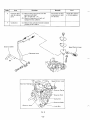
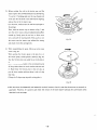
4-11 IGNITION
The ignition system is a flywheel magneto type with ignition timing set at 23" before TDC. The magneto is composed of a
flywheel and ignition coil. The flywheel serving also as a fan is mounted directly on the crankshaft, and the ignition coil in
the crankcase. (For further d e t d s , refer to Section on the Magneto.) (See
Fig. 14 and Fig. 15.)
(SOLID STATE IGNITION TYPE)
(BREAKER POINT IGNTION TYPE)
Ignition Coil
Fig. 15
Fig. 14
-8-
E a \ ?
D
m
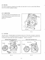
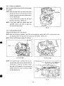
4-12 CARBURETOR
A horizontal draft carburetor is employed. It has been care-
fully set after thorough tests to assure satisfactory start up,
acceleration, fuel consumption, output performance etc.
For construction and order details, refer to the Section on
Carburetor Construction, Disassembly and Reassembly.
(See Fig. i6.)
Fig. 16
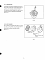
4-13 AIR CLEANER
The air cleaner of the standard type
type using asponge
engine is an oblong
element. (A cyclone typesemi-wet
double element air cleaneris optionally available.)
(See Fig. 17.)
Air Cleaner for
Standard Type
Cyclone Type
(Option)
Mushroom Cyclone Type
(Option)
Fig. 17
-9-
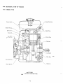
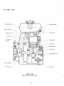
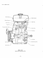
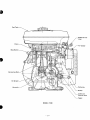
4-14 SECTIONAL VIEW OF ENGINE
4-14-1
MODEL EY15D
Cylinder Head
Blower Housing
Ignition Coil
Piston
Pin
Flywheel
(Cooling Fan)
Starting Pulley
Governor
Recoil Starter
MODEL EY15D
(BREAKER POINT IGNITION TYPE)
- 10
-
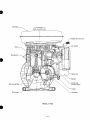
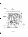
\
I
i
/-Speed
Control Lever
Air Cleaner
Piston
Stop Button
'Carburetor
.Muffler
.Intake and
Exhaust Valve
Connecting Rod
Tappet
1
Camshaft
Oil Scraper-
MODEL EY15D
- 11 -
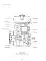
4-14-2
MODEL EY15B
Cvlinder Head
Spark Plug Cap
Blower Housing
Ignition Coil
Spark Plug
Piston Pin
Flywheel
(Cooling Fan)
Piston Ring
Crankcase
Chain Guide
Crankshaft
Main Bearing Cover
Starting Pulley
Recoil Starter
LGovernor
--/
MODEL EY15B
(SOLID STATE IGNITION TYPE)
- 12
-
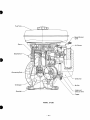
Fuel Tank
1
I
\
Speed Control Lever
Piston
Air Cleaner
Stop Button
Carburetor
Muff Ier
Intake and
Exhaust Valve
Connecting Rod
Tappet
Chain
Oil Scraper
MODEL EY15B
- 13 -
r
4-14-3 MODEL EY20D
Cover
Recoil Starter
Governor
MODEL EYPOD
(BREAKER POINT IGNITION TYPE)
- 14
-
Speed Control
Lever
Piston
Air Cleaner
Stop Button
Connecting Rod
Carburetor
Oil Scraper
Camshaft
.Muffler
\ -
1
Intake and
Exhaust Valve
\“Tappet
MODEL EY20D
- 15 -
4-14-4
MODEL EY28
,Spark Plug Cap
Spark Plug
Flywhe
Piston Ring
Crankcase
l g Cover
-Governor
MODEL EY28
(SOLID STATE IGNITION TYPE)
- 16 -
Fuel Tank
-0 I
Intake and
Exhaust Valve
Tappet
MODEL EY28
- 17 -
PREPARATIONS and SUGGESTIONS
When disassembling theengine,remember
well the locations of individual parts so thatthey can be reassembled
correctly. I f you are uncertain of identifying some parts,it is suggested that tags be attached to them.
Have boxes ready to keep disassembled parts by group.
To prevent missing and misplacing, temporarily assemble each group of disassembled parts.
Carefully handle disassembled parts, and clean them with washing oil.
Use the correct tools in the correct way.
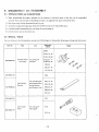
SPECIAL TOOLS
For your reference, the following shows
special tools of Robin Enpne for Disassembiy, Measuring and Inspection Instruments.
Part No.
Tool
Use
Applicable
Model
E YO8
EY10,13,14
EY 15,18,20
2099500407
Flywheel Puller
(with bolt)
For pulling off
Flywheel
EY23,25,27
EY28,33,35
EY40,44
EC05.07,lO
EC17,25,37
23095001 07
€YO8
Valve Spring
Retainer
227 95003 07
For mounting and
dismounting Valve
Spring Retainer
and Retainer Lock
EY10,13,14
EY 15,18,20
EY23,25,27
EY28,33,35
EY40,44
EY08
230 95002 07
205 95001 07
Valve Guide
Puller
For pulling off
Valve guide
EYlO
EY13, 14
- 18-
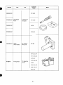
Shape
Part No.
Use
Tool
Applicable
Model
EY 18,23
2069500107
2279500107
I
Valve Guide
Puller
For pulling off
Valve guide
EY 15,20
2349500107
EY28
2079500107
EY25,27
226 9500 1 07
Guide
(Chain Guide)
For mounting
chain guide
EY15B
EY10,13,14
EY 15,18,20
EY25,27
“20248
Timing Tester
For qdjusting
timing
EY33,35,40
EY44
EC03,04,05
EC07,10,17
EC25,37
- 19 -
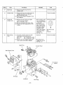
5-3 HOW TO DISASSEMBLE
*Length of the bolt indicates the length from the bolt head bottomsurface to the threaded end.
I
Order
1
Item
Procedures
Remarks
I
:
Drain plug
(1) Drain engine oil.
Drain plugs on both sides of the
crankcase.
Recoil starter
(1) Remove the recoil starter.
6@x 8 mm Flange bolt: 4 pcs.
Be careful not to lose
the gasket.
14 mm spanner
10 mm box spanner
Gasket
- 20 -
Tool
Item
Order
Remarks
Procedures
Tool
~~
~
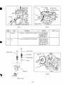
3
Blower housinl
(1) Remove the Blower housing from the
crankcase and head cover.
EY15,20 . . . 64 x 12 mm bolt: 2 pcs.
6q5 x 14 mm bolt: 2 pcs.
EY28 . . . . . . 6q5 x 12 mm bolt: 4 pcs.
4
Fuel tank and
head cover
(1) Close the fuel cock.
(2) From the carburetor disconnect the fuel
pipe between the fuel strainer and carburetor on the side of the fuel strainer.
(3) Remove the fuel tank from the cylinder
head.
EY15,20 . . . 64 nut: 2 pcs.
EY28 . . . . . . 84 nut: 4 pcs.
(4) Remove the head cover from the cylinder
head.
10 mm spanner or
12 mm spanner
Air cleaner
(1) Remove the air cleaner cover and element. Air cleaner is fasten(2) Remove the air cleaner case from the car- ed together with the
buretor.
carburetor.
6rp nut: 2 pcs.
(3) Disconnect the breather pipe.
10 mm box spanner
Muffler cover
(1) From the muffler remove muffler cover.
EYl5,20 . . . 64 x 8 mm bolt: 3 pcs.
EY 28 . . . . . 6q5 x 8 mm bolt: 4 pcs.
10 mm box spanner
Muffler
(1) Remove the muffler from the cylinder
portion of the crankcase.
8q5 nut: 2 pcs.
7
Fastened together
with the fuel tank
Brass nut
10 mm box spanner
12 mmspanner
Muffler Cover
/I
6”.
Mu’ffler
- 21 -
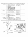
Order
I
Item
Procedunx
Remarks
8
Governor lever
and the relative
parts
(1) Remove the governor lever from the
governor lever shaft.
6$1x 25 mm bolt: 1 pce.
(2) Remove the governor rod and rod
spring from the carburetor.
9
Carburetor
(1) Remove the carburetor from the cylinder
portion of thecrankcase.
Just loosen the bolt,
unnecessary to take
out the bolt.
1
Tool
10 mm box spanner
or 10 mm spanner
~
~~
Lever
Fig. 18
- 22 -
Order
I
I
Rocedu~s
Item
"
10
Starting
pulley
Remarks
Flywheel
(1) Remove the flywheel from the crankshaft
Fit the flywheel pull- Flywheel puller
er as shown in Fig.20,
turn the center bolt
clockwise and pull
out the flywheel.
(1) Remove the ignition plug cap from the
ignition plug; and remove the i p t i o n
coil from the crankcase.
64 x 25 mm bolt: 2 pcs.
Sems bolt
-
~
19 mm box spanner
or 24 mm box
spanner
1
~
10 mm box spanner
Spark Plug Cap
(Solid State lgnitio
\
Flywheel Puller
Fig. 20
- 23 -
I
10 rnm box spanner
Be careful not to
damage the blades
of the flywheel with
a driver and a like.
Strike counterclockwise with a hammer.
(See Fig. 19.)
"
Ignition
12 coil
Tool
(1) Remove the starting pulley from the flywheel.
64 x 12 mm bolt: 3 pcs.
Fit a box or socket
wrench over the
a
flywheel nut, and strike it hard with
hammer to remove the nut (EY15,20:
14 mrn, EY28: 18 mm) and spring
washer.
"
11
I
0
\
Flywheel
Order
13
Remarks
Procedures
Item
(1) Remove the spark plug from the
Spark plug
I
Tool
21 mm box spanner
cylinder head.
~~
~~
~~
~~
14
Cylinder head
(1) Remove the 8 mm bolt and remove the
cylinder head from the crankcase.
89 x 40 mm bolt: 8 pcs.
(2) Remove the cylinder headgasket from
the crankcase.
15
Intake and
exhaust valve
(1) Remove the inner and outer tappet
covers from the crankcase.
69 x I 2 mm bolt: 2 pcs.
( 2 ) Pull out the intake and exhaustvalve.
(3) Remove the valve spring and the valve
retainer .
16
Main bearing
cover
~
12 mm box spanner
Put the notch on the
outer circumference
of the spring retainer
on this side.
Hook the medium
size (-) drive at the
dent (lower side) of
the spring retainer
and pull out the
valves, while pulling
the spring retainer
toward you.
(See Fig. 2 1 .)
Sems bolt
(1) From the crankcase remove the bolt
fastening the main bearing cover.
EY 1 5 , 2 0 . . . 6$ x 30 mm bolt: 8 pcs.
EY28 . . . . . . 8$ x 28 mm bolt: 8 pcs.
(2) Remove the cover, lightly tapping the
cover evenly with a plastic hammer.
Spark Plug
10 mm box spanner
The front is this
side.
(-) driver
10 mm box spanner
Be careful not to
damage the oil seal.
(See Fig. 22.)
Cvlinder Head
Cyclone
Cleaner
I
Drain Plug
Crankcase
- 24 -
,
”
.
Oil Seal Guide
Main Bearing Cover
J
L
Fig. 21
F&. 22
(1) Remove the camshaft from the crankcase.
~
18
~~
~~~~
~~
~~~~~
(1) Remove the tappets from the crankcase.
Tappet
9 -1
Intake Valve,
Tool
Remarks
Procedules
To prevent the tappets from falling or
damaging, place the
crankcase on t h e
side. (See Fig. 23.)
~
Before removing put
a mark of intake or
exhaust on each tappet. In the EY 15B
type, remove the tappets after step 2 1 .
Exhaust
Valve
Valve Spring
Spring Retainer
Tappet
I
!
Camshaft
I
Tappet
Fig. 23
GoGernor Gear
- 25 -
Order
(1) Scrape off carbon and other foreign de-
I
Piston and
piston pin
20
I
I
Connecting rod
and piston
19
Remarks
Procedures
Item
I
posits from the upper parts of thecylinder and piston, and then straighten out
the bent tabs of the lock
washers on
the connecting rod, and remove two
pieces of the bolt.
( 2 ) Remove the oil scraper, lock washer and
connecting rod cap from the crankshaft.
(3) Turn the crankshaft until the piston is
raised up to the highest position, push
the connecting rod up, and remove the
piston out of the top of thecylinder.
(1 j Remove the two clips, pull out the piston
pin, and take the piston off from the
small end of the connecting rod.
(2) Spread the open ends of the piston rings
and remove them frGm the piston.
I
(1) Remove the woodruff key (for the
magneto).
Tool
i
In the EYI 5B type,
move the connecting
rod to the position
shown in Fig. 24.
10 mm box spanner
or 10 mm spanner
Be careful not to
damage the inside
of the small end of
the connecting rod.
Be careful not to
break the rings by
spreading too much.
Be careful not to
damage the oil seal.
(2) Lightly hammer the magneto end of
the crankshaft, andpull it out of the
crankcase.
22
Crankshaft
(1) Remove the woodruff key (for the
Camshaft Chain
magneto).
(2) Remove the crankshaft and the camshaft
(for EY15B)
at thesame time from the crankcase,
tapping the crankshaft tipin the magneto
side.
Be careful not to
damage the oil seal.
To prevent the tappets
from failing or d a m aging, place the crankcase on the side.
Piston R i n g
Piston
iston Pin
"
j o o d r u f f Key
Connecting Rod
\
Crankshaft
Fig. 24 (E Y 15B)
- 26 -
5-4 HOW TO REASSEMBLE
.Precaution in reassembling
Every and each part should be cleaned thoroughly. Especially, pay utmost care and attention to the cleanliness of the
piston, cylinder, crankshaft, connecting rod and bearings.
Scrape completely off carbons from the cylinder head and the upper part of the piston; especially the carbon adhered
in the groove of the piston ring should be carefully and completely taken out.
Carefully check the lip portion of every oil seal. If faulty one is found, replace it without any hesitation.
Apply enough oil to thelip portion of the oilseal when reassembling.
Replace all the gaskets with new ones.
Replace the key, pin, bolt, nuts, etc.
with new one,if necessary.
Whenever tightening torque is specified, conform to thespecified figures.
Apply oil to therevolutionary parts and friction surfaces, when reassembling.
Check and adjust the clearances of variousportions and then reassemble.
When some main portions are assembled in the course of reassembling, turn or move the gadgets by hand and pay attention to thefrictional noise and resistance.
*Sequence and precautions in reassembling
5-4- 1 CRANKSHAFT
1)
Fit the oil seal guide onto the end of the crankshaft,
and insert the crankshaft into the crankcase as shown
in Fig. 25.
NOTE: In case of not using the oil seal guide, be careful not to damage the oil seal lip.
2) Put woodruff key (for magneto) in place.
I.
Fig. 25
- 27 -
3) DIMENSIONS of CRANKSHAFT PIN
D (Crankshaft pin Dia.)
PISTON RING GAP
0.090L
-
0.135L
0.050L
-
0.01 OL
-
0.065L
- 0.065L
PISTON RING SIDE
CLEARANCE IN GROOVES
OIL R I N G
-
DIA.
CONNECTING ROD TO
CRANK PIN
SI DE
0.063L
0.1 L
CONNECTING R O D T O P I S T O N P I N
0.01OL
PISTON PIN T O P I S T O N
0.009T
-
-
- 0.09OL
0.095L
0.050L
0.01OL
0.020L
-
0.065L 0.01OL
- 0.046L 0.037L
0.3L
0.029L
0.01 OL
L : LOOSE
TT: I G H T
Table 1
54-2 CRANKSHAFT,CAMSHAFT,CHAIN
TAPPET (for EYISB)
1)
and
Ling Plate (White)
& A
Set the chain in the sprockets of the crankshaft and
the chamshaft, as shown in Fig. 27.
NOTE: Set thechain
so thatthewhite
matches to the timing marks
link plate
of the crank-
shaft and the camshaft.
2) Put thetappets
in the crankcase, andthen set the
crankshaftandthecamshaftparallel.Thenmount
them onto the crankcase.
V
Timing Mark
,”--
Fig. 27 (EY 15s)
- 28
-
54-3 PISTONand PISTON RING
1)
If no ring expander is available, install the rings by placing the open ring ends over t h e first land of the piston and
spreading the rings only far enoughto slip them over the correct k g grooves.
NOTE: Pay attention not to break the rings by twisting. Install the oil ring first followed by the second ring and then
top ring. Meantime, the surfaces of the second ring and the top ring with carved marks are t o be faced up.
I
Ring
Piston
I
I
Fig. 28
I
I
EY15,20
I
Face
Top Ring
Barrel
I
EY28
Taper
Second Ring
Taper Under Cut
.-
Oil Ring
Cutter Ring
(without expander)
Fig.
2)
29
Reassemble the piston and connection rod by means of the piston pin.
NOTE: Apply enough oil t o the small top end of the connecting rod.
Be sure to place the clipson both ends of the piston pin.
- 29 -
(with expander)
...
J
3) When installing theconnecting
I
rod into place,
hold
piston rings with the ring guide as shown in Fig. 30
(if no ring guide is available, keep pressing the piston
rings with finger tips and gently strike the top of the
Piston Ring Guide
piston with a wooden piece or the like to push it in),
@or mark MA on the conand check that the symbol
necting rod is in the direction of the flywheel magneto.
NOTE: Apply enough oil to the piston rings, connect-
ing rod plain bearings and cylinder wall before
reassembling.
NOTE: The open ends of the piston rings must be 90"
apart from one another on the piston periph-
Fig. 30
ery .
NOTE: The clearance between the piston and cylinder must
be measured a t the piston skirt thrust surface.
5 4 4 CONNECTING ROD
1)
Turn the crankshaft to the bottom dead center, lightly hammer the piston head
until the connecting rod
contacts the crankpin, andassemble.
2) When reassembhg the connecting rod cap, match the
alignment projection markon the rod.
3) Oil scraper is to be set on the side of magneto. (See
Fig. 31 .)
NOTE: Use new lock washers, and bend the tabs se-
curely.
NOTE: After reassembly, confirm that theconnecting
rod moves lightly.
I
Alignment Mark
NOTE: Connection rod cap tightening torque:
EY15
EY20
EY28
. , . .... . . . .
... . . .. .
+-
Fig. 31
90- 115 kg-cm
170
- 200
kg-cm
NOTE: For the piston, piston ring and rod clearance, see Fig. 26.
- 30 -
Oil Scraper
5-4-5 TAPPET and CAMSHAFT
Insert the tappets back into their holes first, and then mount
the camshaft.
NOTE: Align the timing mark a t the root of a tooth of the
cam gear with the one on the crank gear. If thevalve
timing is wrong, the engine cannot operateproperly
or a t all. (See Fig. 32.)
In the EY158, set thewhite
link plate a t the
sprocket’s timing mark. (See Fig. 27.)
NOT€: If theintaketappet
and
exhaust
tappet
were
assembled contrarily each other,thetappet
clear-
ance cannot be kept correctly.
Fig. 32
5-4-6 MAIN BEARING COVER
Install the main bearing cover to the crankcase.
NOTE: When the chain guide is replaced in the EY158, use the guide (chain guide)
(See Fig. 33.1, or set the chain so that
the clearance between the chain and the chain guidsi s from 0 to 0.5mm. (See Fig. 34.)
NOTE: CHAIN GUIDE tightening torque 70 to 90 kgcm.
Chain Guide
n
n
Fig. 33 (E Y 75B)
NOTE: As the governor gear is mounted on the main bearing cover side, install the main bearing cover while
Fig. 34 (E Y 156)
I\
checking that it meshes with the teeth of the cam
gear. {See Fig. 35.) Meantime, if the oil seal need be
replaced, pressure-fit a new oil seal before installing
the main bearing cover.
- 31 -
Pay attention t o the engagement of
the governor gear and cam gear
NOTE: When installing main bearing cover, apply oil to the
bearingand oil seal lip. Fit the oil seal guideover
the crankshaft or camshaft
lipfrom
damage.
to protect the oil seal
Thenplacethemainbearing
cover on.
Check the crankshaft and camshaft their side clearanceare 0
-
0.2 mm; and if not adjust them with
theadjusting
Fig. 36.) (In D type,
shims.
(See
adjustment of the camshaft is not necessary)
Fig. 36
I
NOTE: Main bearing cover tightening torque:
......
... .. ......
EY15, E Y 2 0 .
EY28
8 0 - 100 kg-cm
170
-
Dial Indicator
190 kgcm
NOTE: Fig. 37 showsone of themethodsmeasuringthe
11
II
crankshaft and camshaft side clearance between the
machined face of the crankcase and adjusting collar.
As a paper packing i s used on the machined face of
the crankcase,adjust
the clearance by taking this
thickness of 0.22 mm into account. (See Fig. 37.)
-32
-
11
Y=II
Ground Surface of Crankcase
(The surface of the crankcase is t o be
put together with the surface of the
main bearing cover.)
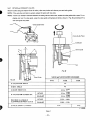
5-4-7 I N T A K E a n d E X H A U S T V A L V E S
Remove carbon and gum depositefrom the valves, valve seats, intake and exhaust ports and valve guides.
NOTE: If the valve face is dinted or warped, replace t h e valves w i t h n e w ones.
NOTE: If there is an excessive clearance between the valve guide and valve stem, replace the valve guide
with a spare. F o r re-
placing, pull out the valve guide, using the valve guide pulling base and bolts as shown in Fig. 38, and pressure-fit a
new valve guide into place.
Valve Guide Puller
Valve Guide Puller
Crankcase
E
Valve Guide
Nut
Fig. 38
V A L V E and VALVE GUIDE CLEARANCE
F&. 39
EY15
EY20
A-VALVE FACE ANGLE
45O
B-SEAT ANGLE
45O
6.5 dia. +0.022
C-GUIDE INSIDE DIA.
D - V A L V E S T E M O U T S I D E DIA.
MAXIMUM ALLOWABLE
C L E A R A N C E B E T W E E N C and D
EY28
INTAKE
6.5 dia.;:::1
:
EXHAUST
6.5 dia.
;:::1
INTAKE
0.025L
EXHAUST
0.056L
€ - V A L V E S T E M TILT ANGLE
3"53'
- 0.062L
- 0.looL
3"30"
L: LOOSE
Table 2
- 33 -
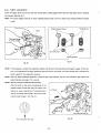
5-4-8 TAPPET ADJUSTMENT
Lower the tappet all the way down, push the valve,
and insert a feeler gauge between the valve and tappet stem to measure
the clearance. (See Fig. 40.)
NOTE: The correct tappet clearance for both intake and exhaust valves is 0.1 mm
* 0.02 mm as measured when the engine
is cold.
Spring
Valve
Valve
Exhaust
Intake,
vT/
Grinding Face
i
..
I
-
Spring Retainer
Tappet
Fig. 41
Fig. 40
NOTE: If the clearance is smaller than specified, slightly grind the top of the valve stem, and measure it again. On the contrary, if the ciearance is too large, replace the valve with new one, and polish its contact surface with a compound to
obtain a good fit. Then adjust the clearance.
NOTE: After the tappet clearance adjustment,
install the valve spring retainers, and turn the crankshaft, and measure the
tappet clearance once again if it is correct.
NOTE: INSTALLATION of SPRING RETAINERS
Place the notch on the outer circumference of the
retainer toward this side and insert the retainer, like
pushing in, using a special tool. (This special tool is
used for EY18 and other models.) If adriver isused,
insertion may be easier. (See Fig. 42.)
I
Valve Spring Retainer
Fig. 42
Front should be this side.
- 34
-
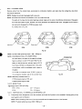
54-9 CYLINDER HEAD
I
I
particularly its combustion chamber, and make clean the cooling fins.Also check
Remove carbon from the cylinder head,
the head for distortion.
NOTE: Replace the cylinder head gasket with a new one.
NOTE: DlSTlNGTlON between the GASKET ofEY15, EY20and EY28
The pitch of the holes for the bolts fastening cylinder head and the outer circumference dimensions of the gasket
for EY15 and EY20 are same. However, the inner dimensions are different each other. The gasket for EY15 has a
red mark while the gasket for EY20 has a green mark.
For EY28, refer to Fig. 43.
Green mark
Red mark
EY28
-
Fig. 43
NOTE: Cylinder head tightening torque: 190
-
230 kg-cm
NOTE: DISCRIMINATION of CYLINDER HEAD
Embossed mark
As stated above, the pitch of the holes of cylinder
head is common to both EY15 and EYZO. For enabling to discriminate the cylinder head of EY15
from that of EY20, anembossed mark 15 is given
to the former, while no embossed mark is given t o
the latter.
For EY28, anembossed mark "EY28" is given on
combustion
the
chamber
side
Fig. 44
of the cylinder head.
NOTE: Meantime, embossed mark forEY15 Kerosene engine is 15K. and
EY20 Kerosene engine is 20K.
5-4-10 SPARK PLUG
Tightening torque of the spark plug:
E Y l 5 , EY20 . . . . . . . . . . . 120
EY28 . . . . . . . . . . . . . . . 230
5-4-11 IGNITION
1)
- 150 kg-cm
-
250 kg-cm
COIL, FLYWHEEL and STARTER PULLEY
Temporarily fasten the ignition coil to the crankcase, and install the flywheel to the crankshaft. Starting pulley is fastened together with the flywheel.
NOTE: Before installing, wipe out oil fromthe crankshaft and the tapered portion of the flywheel.
NOTE: Flywheel tightening torque: 600
- 650
kg-cm
- 35
-
2) After measuring the air gap between the ignition coil
.
/"
and flywheel, retighten the ignition coil. (See Fig. 45.)
Air gap: 0.5 mm
1
\
\
I
Fig. 45
5 4 - 1 2 CARBURETOR
To the cylinder portion of the crankcase. install in the order of thegasket, insulator, gasket and carburetor, and then mount
the air cleaner and fasten with two pieces of 6 mm nut.
54-13 GOVERNOR
LEVER
When reassemblying, refer to the7 . GOVERNOR ADJUSTMENT.
5-4-14 MUFFLER and MUFFLER COVER
,
"
-
With two pieces of the brass nut fasten the muffler to thecrankcase and then install the muffler cover.
54-15 HEAD COVER, FUEL TANKand FAN COVER
Install in the order of the head cover, fuel tank and fan cover.
NOTE: If these items are installed in the order of the head cover, fan cover and fuel
be impossible.
54-16 RECOIL STARTER
With 4 pieces of 69 x 8 mm bolt fasten the recoil starter.
NOTE: It is feared that the bolt longer than 8 mm may damage the blades.
- 36 -
tank, removal of the fan cover would
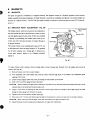
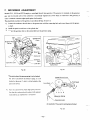
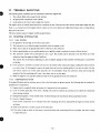
6. MAGNETO
6-1 MAGNETO
The spark for ignition is furnished by a magneto assembly. The magneto consists of a flywheel, ignition coil and contact
breaker assembly (including condenser), of which flywheel is mounted on crankshaft and ignition coil contact breaker are
mounted in crankcase directly, The EYl5B type engine normally incorporates a solid state ignition system (T.1.C) described in 6-5.
The breaker points, whch are mounted in the crankcase inside the flywheel should be checked twice a seasonor whenever the ignition spark becomes weak.If there is an evidence
of pitting or pyramidding, the breaker points must be corrected, and then it becomes necessary t o readjust the gap t o
its proper clearance.
The normal breaker point opening (point
gap) is 0.35 mm
Contact
Breaker
at full separation. Since the spark timingof 23" is regulated
by the point
opening, use a timing light
curatesparkadvance.(Refer
to obtain an ac-
t o '6 -3 TIMING ADJUST-
MENT.")
Fig. 46
To adjust breaker point opening, remove starting pulley, blower housing and flywheel from the engine and proceed
follows: (See Fig. 46.)
as
1) Remove breaker cover from contact breaker.
2) Turn crankshaft over until breaker arm comes in contact with the high point of the breaker cam. (Maximum point
opening of 0.35 mm)
3) Loosen contact support plate lock screw just enough so that bracket can be moved.
4) Insert a 0.35 mm feeler gauge between the points.
CAUTION:
Adjust breaker point gap without opening it more than 2 mm, otherwise rated heel-pressing force may not be
obtained due t o the bending of contact breaker arm.
5) Apply a screw driver t o adjusting tab and move the contact support plate justenough so that a slight drag is felt while
sliding the feeler gauge from between the points.
6 ) Tighten lock screw and recheck breaker point gap.
7) Pull a strip of 8
- 10 mm wide white paper through the closed points toremove oil and dust on the point surfaces.
CAUTION: When inserting a sheet of paper, never open the breaker point gap more than 2 mm.
8) Mount flywheel, blower housing and starting pulley on engine after adjustment.
.'
- 37 -
'
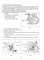
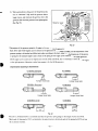
6-3 TIMING ADJUSTMENT (See Figs. 47,48 and 49)
The spark is timed to occur at 23” before the piston reaches
TDC on the compression stroke. This spark advance of 23” is
controlled by the breaker point opening and tius advance is obtained when the breaker point opening is adjusted according
to the BREAKER POINT ADJUSTMENT to its proper point gpening. However, the advance timing is more accurately ad-
justed through the following procedures using a timing tester as shown in Fig. 48.
NOTE: Refer t o section “4-1’1 IGNITION” and “13. CHECKS and CORRECTIONS.”
6-3-1 ALIGNMENT MARK for TIMING
ADJUSTMENT
(See Fig. 47.)
For timing adjustment,the
1
following alignment
marks are provided as shown in Fig. 47.
* ‘M” mark and line on
* ‘P-
the crankcase
mark and line on fhe flywheel cooling fan
Fig. 47
/-
6 - 3 - 2 TIMING ADJUSTMENT with TIMING TESTER
1)
Bsconnect the stop button lead wires and the coil primary wire.
2) Remove blower housing from engine.
3) Connect the timing tester lead with red rubber cap to the coil primary wire and ground the lead with b!ack rubber cap
to the crankcase. (See Fig. 48.)
While the points are open, the buzzer within tester remains ringing and when the points are closed, the tester remains
silent. (See Fig. 48.)
4)
Turn the flywheel slowly until alignment mark on the flywheel is in the line with alignment mark on the carankcase.
Fig. 49
Fig. 48
- 38 -
Remove the flywheel without turning crankshaft at
all.
Loosen the lock screw of the breaker point support plateso that the breaker point canbe rotated.
By rotating the support plate of the breaker point, fmd the exact point
when the buzzer within timing
tester starts
ringmg from being silent. (SeeFigs. 48 and 49.)
Put the flywheel back and check by rotating flywheel slowly. If the buzzer in timing tester starts ringing when line
mark on the flywheel is in the line with line mark on the crankcase. When the line marks are in alignment, the timing
is correct.
If the timing mark lines are not in alignmnent, then readjust the point opening according t o the BREAKER POINT
ADJUSTMENT, by removing the flywheel and repeat the checking procedure 3) through 5).
After completing the timing adjustment remount the blower housing and connect the
coil primary lead to the stop
button.
MAGNETOTROUBLESHOOTING
When the engine does not,start or starts with difficulty, or when its operation is unstable, the following tests will clarify if
they are caused by a defect in the magneto.
1) Check igntion cable for possible corrosion, broken, worn insulator or loose connection.
2) Check the sparking as described later in this section.
3) Check if the breaker points require cleaning, or adjusting o r not. If the points are badly corroded or pitted, condenser
may have t o be replaced too.
Refer to ‘BREAKER POINT ADJUSTMENT.”
4) If no spark takes place, replace igntiion coil.
*SPARK TESTING
Remove spark plug from cylinder head and place iton blower housing, with the ignition cable connected to it.
Crank the engine several times by starting pulley and observe the spark in the spark gap of spark plug. If the spark is
strong, the ignition system can be eliminated
as the source of trouble.
If the spark is weak or there is no spark at all, repeat the checks accordingto theprocedures 1) through 3) above.
The correct electrode gapis 0.6
-
0.7 mm. (Refer to section “15. CHECKS and CORRECTIONS.”)
6-5 SOLID STATE IGNITION (SeeSection
details.)
10 “ROBIN SOLID STATE IGNITIONENGINE”
for
The following solid state ignition systems are available as optional or standard:
1) T.I.C. (TRANSISTORIGNITIONCIRCUIT)
(EY15, EY20, EY28)
On the outside of the flywheel, an igntiion coil is installed, which is so-called outer coil type. This is equipped to the
standard type engine, and the exciter
coil (primary-excitation) is available as an optional part. (The flywheel is for
common use.) (See Fig. 59.)
2) P. I. T. (PULSER IGNITION TRANSISTOR) (EY 15, EY20)
The ignition coil and lighting coil are installed inside the flywheeel. Thls built-in type ignition system is installed to
the engine in w h c h lighting coil is requested. (P.I.T. unit is installed on the outside of the flywheel,)
- 39 -
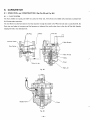
7. GOVERNE
Models EY 15, EY20 and EY28 employ a centrifugal flyweight
type governor. The governor is mounted on the governor
gear and the throttle valve of the carburetor is automatically regulated by a lever which is connected to the governor in
order to maintain constant engine speed against load variations.
The adjustment procedure of the governor is as follows (See Figs. 50 and 5 1.):
1)
Connect the carburetor throt?le lever t o the governor lever with the connecting link,and mount them onto the govern
or shaft.
2) Install the speed control lever to the cylinder head.
3) Connect the governor lever to the controllever with the governor spring.
I
Fig. 51
Fig. 50
*The point where the governor spring i s to be hooked
For EY15 and EY28 thegovernorspring
is to be
hooked at the point 1, while it is to be hooked at the
point 2 for EY20.
4)
Turn rhe control lever towards high speed, and confirm that the carburetor throttle valve is fully opened.
Control lever can stay wherever it is required.
I'
Governor Lever
An example of the governor spring being hooked
Fig. 52
-40 -
5 ) With a screwdriver in the groove of the governor shaft,
turn it 'clockwise" fully until the governor shaft no
longer moves, and then lock thegovernor lever to the
governor shaft with the governor lever tightening bolt.
(See Fig. 53.)
Governor Lever
Fig. 53
*Dimensions of the governor spring for the engine to beconnected to thegenerator:
Both EY 15 and EY20 engines can be connected to the generators of both 50Hz and 60Hz;and the'dimensionsof the
governor spring t o be hooked are different each otheraccording to the hertz. Meantime, the dimensions of the governor spring for the standard engineis same as those of the spring for the engine t o be connected to the 60Hz generator.
EY28 engine can be connected to the generators of both 50 Hz and 60 Hz; but it is necessary to select the right engine
to the right generator. Meantime, standard type engineis for the 60 Hz generator.
Discrimination according to the dimensions:
EY15/60Hz (Standard)
EY 15/50Hz
-I(a)
I4Al-l
(Longer Hook Side)
(Longer Hook Side)
EY20/60Hz (Standard)
-::-
"
--I (all"
(Longer Hook Side)
EY28/60Hz( STD)
EY20/50Hz
"
(A)
(Longer Hook Side)
EY28/50Hz
Fig. 54
*For EY15, EY20 and EY28 it is commonly said that the governor spring longer in the length of (A) is for 50 Hz.
*Both ends of the spring for EYI 5 are bended to the same direction, while both ends of the spring for EY20 are bended to contrary directions.
-41 -
8. CARBURETOR
8-1 OPERATION and CONSTRUCTION (See Fig. 55 and Fig. 56.)
8-1-1
FLOAT SYSTEM
The float chamber is located just below the carburetor body and, with a float and a needle valve, maintains a constant fuel
level during engine operation.
The fuel flows from the fuel tank into the float chamber through the needle valve. When the fuel rises to a specific level, the
float rises; and when its buoyancy and fuel pressure are balanced, the needle valve close to the shut off the fuel, thereby
keeping the fuel at the reference level.
r By-Pass
I
,-
Choke
Pilot Jet
I
Throttle Valve
n
. Main
Nozzle
Pilot Outlet
Main Air Jet
Body
/-'-
Float
Main Jet
Fig.
55
Needle
Float
- 42 -
8- 1 - 2 PILOT SYSTEM
The pilot system feeds the fuelto the engine during idlingand low-speed operation.
The fuel is fed through the main jet to the pilot jet,
where it is metered, and mixed with the air metered by.the pilot air jet.
The fuel-air mixture is fed to the engine through the pilot outlet and the by-pass.
During engine idling, the fuel is mainly fedfrom the pilot outlet.
8-1- 3 MAIN SYSTEM
The main system feeds the fuelto theengine during medium- and high-speedoperation.
The fuel is metered by the main jet and fed to the main nozzle. The air metered by the main air jet is mixed with the fuel
through the bleed holes in the main nozzle, and the mixture is atomized out of the main bore. It is mixed again with the air
taken through the air cleaner into an optimumfuel-air mixture, which is supplied to the engine.
8-1-4 CHOKE
The choke is used for easy start in the cold season. When the recoil starter is pulled with a closed choke, the negative pressure applied to the mainnozzle increases and draws much fuel accordingly; thus easily start up theengine.
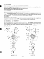
8-2 DISASSEMBLY and REASSEMBLY
Apart from mechanical failures, most of carburetor troubles are caused by an incorrect mixing ratio, which may arise mainly
due t o a clogged up air or fuel passage in jets, or fuellevel variations. In order t o assure proper flow of a i r and fuel, the carburetor must be kept clean at all times. The carburetor disassembly and reassembly procedures are as follows:
(See Figs. 57 and 58.)
"i
4
29
1 3
7
7
-4gJ
I
8
12
* 8
l
A
l1
12
0
"---@
e
4
Fig. 58 (EY28)
Fig. 57 ( E Y 15,201
-43
-
8 - 2 - 1 THROTTLE SYSTEM
1)
Remove the Philips screw (27) and throttle valve (22), and pull out the throttle shaft (23).
2) The spring (24) can be taken out by removing the throttle stop screw (25).
*Exercise care not to damage throttle valve ends.
8 - 2 - 2 CHOKE SYSTEM
and pull out the choke shaft (1 6 ) .
1)
Remove the Philips screw (14) and choke valve (1 9
2)
When reassembling the choke shaft, make sure that the cutoutin the choke valve faces the main air jet.
,
Meantime, when reassembling the moderation regulating ball (20) and the
spring(21), set these parts at the right
positions with the rings (1 8) and (19) and then reassemble.
8 - 2 - 3 PILOT SYSTEM
1)
Remove the pilot jet (26), using correct tool to avoid damage to it.
2)
Reassembly
Tighten the pilot-jet securely. Otherwise, the fuel may leak, causing engine malfunction.
8 - 2 - 4 MAIN SYSTEM
1)
Remove the bolt (1 2) and take out float chamber body (lo).
2)
Re-move the main jet (13) from the body (6). [In case of EY28, remove the main jet (13) from the pipe assy (29),
and then remove the pipe assy (29) and the nozzle (28) from the carburetor body(6).]
3)
Reassembly
a) Fasten the main jet securely to the body.Otherwise, the fuel may become too rich and cause engine malfunction.
b) The bolt tightening torque is 70 kg-cm.
8 - 2 - 5 FLOAT SYSTEM
Ij
Pull out the float pin (9) and remove the float (8) and needle valve (1 7). If the needle valve need be replaced, replace
i t with rubber needle.
CAUTION: When cleaning the jets, use neither a drill nor a wire (because of possible damage of the orifice which will
adversely affect fuel flow). Be sure to use compressed air to blow them clean.
2 ) When removing the needle valve and floats, gently tap the reverse side using the rod more slender than the float pin
and remove because the float pin is calked to the carburetor body.
- 44 -
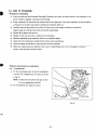
9. BREAK-INOPERATION
An overhauled engine must be operated
of REASSEMBLEDENGINE
at low speed break-in the parts.
A thorough break-in is indispensable particularly
when the cylinder, piston,:piston rings or valves are replaced with new ones.
The recommended break-in schedule is shown below.
LOAD
EY28 EY15
I
I
I
SPEED
EY20
NO LOAD
2,500 rpm
10 minutes
NO LOAD
3,000rpm
10 minutes
NO LOAD
1.35 HP
2.7 HP
1
I
TIME
CRANKSHAFTREV.)
1.75 HP
3.5 HP
I
I
I
rpm 3,600
I
I
2.75 HP
5.5 HP
-45
-
3,600
rpm
3,600 rpm,
1
I
I
10 minutes
30 minutes
60 minutes
10. ROBIN SOLID STATE IGNITION ENGINE ('F.I.C. and P.I.T.)
r
10-1 FEATURES
Model EYl5D and EY20D can employ as option a pointless ignition system, called Solid State Ignition, w h c h is the circuit
breaker type ignition device, utilizing the power transistor as an element for controling eiectric current. There are two types
of this system, the one is outer coil type without pulser and is called T.I.C.(Transistor ignition circuit type) and the other
type has a built-in pulser coil andis called P.I.T. (Pulser transistor type). T.I.C. is a standard ignition system for EY28D, B.
Being different from the breaker point type ignition system, this brand-new systemis completely free from such troublesas
startingup failure owing t o dirty, burnt or oxidized point surface, lowering of ignition efficiency being caused by moisture,
rough surface of breaker point and incorrecttiming resultant from worn mechanical parts.
10-2 BASIC THEORY of T.I.C. (See Fig. 59.)
T.I.C. (Transistor ignition type) consists ofthe flywheel and
ignition
with
coil
built-in
transistor;
its
and
basic theory is as
Resister
follows:
Revolution of the flywheel generates electricityon the
I
T
Ignition Coil
1
1
I
1
primary side of the ignition coil, and the electric curm
rent A runs. A makes the power transistor 'ON" and
.-
the electric current B passes.
&
The flywheel goes round further, and at the time o f
ignition the electric current
C runs, then the electric
current D runs to the signal transistor, by which the
electric current B, passing through the power transisFig. 59
tor, is abruptly cut; and as a result, the high voltage
electricity is generated on the secondary side of the
ignition coil and it sparks at theplug.
10-3 BASIC THEORY of P.I.T. (See Fig. 60.)
P.1.T @her ignition transistor type) consists of the ignition coil, P.I.T. unit and flywheel; and its
basic theory is
as follows:
1) Revolution of the flywheelgenerateselectricity on the
primary side of the ignition coil, and the electric current A runs. A makes the power transistor
"ON" and
the electric current B passes.
2 ) Theflywheelgoesround
further, and at the time of
ignition, the pulser coil generates electricity, and
electriccurrent
C
the
runs; and SCR becomes "ON."
Then, the electric current D runs, by which the electric current B is cut abruptly, and as a result the high
Fig. 60
voltage electricity is generated on the secondary side
of the ignition coil and it sparksat theplug.
- 46
-
C
8
01
v)
X
I"
11. TRQU
The following three conditions must be satisfied for satisfactory
engine start.
1. The cylinder
filled with a proper fuel-air mixture.
2. An appropriate compression in the cylinder.
3. Good sparks at the correct time to ignite the mixture.
The engine cannot be started unless these three conditions are met. There are also other factors which makeengine start difficult, e. g., a heavy load on the engine when it is about to start at low speed, andhigh
a back pressure due to a long exhaust
pipe, justt o say a few.
The most commoncauses of engine troubles aregiven below:
11-1 STARTING DIFFICULTIES
11-1-1
FUEL
SYSTEM
No gasoline in th fuel tank; or the fuel cockis closed.
The carburetor is not choked enough, particularlywhen the engine is cold.
Water, dust or gum in the gasoline block flow of the fuel to the carburetor.
Inferior grade gasoline or poor quality gasoline
is not gasfied enough to produce the correctfuel-air mixture.
The carburetor needle valve is held open by dirt or gum. This trouble can be detected as the fuel flows out
of the
carburetor when theengine is idling. (Overflow)
T h ~ strouble may be remedied, depending oncases, by lightly tapping the float chamber with the grip of a screwdriver
of the like.
If the carburetor overflows, excessive fuelruns into the c y h d e r when starting the engine,making the fuel-air mixture
too rich to burn. If this happens, remove the spark plug, and turn the starting pulley a few turns in order
to let the
rich fuel-air mixture out of the spark plug hole into the atmosphere. Keep the carburetor choke open during this
operation. Dry the spark plug well, screw it into place, and try to startagain.
7 ) When the engine is cold, pull the carburetor knob to let thegasoline flow into the carburetor.
11-1-2 COMPRESSIONSYSTEM
If starting difficulties and loss of power are not due to the fuel system or ignition system, the following mustbe checked for
possible lack of compression.
1) Engine inside is completely dried up because of a long periodof non-operation.
2) Loose or broken spark plug. This causes a hissing noise made by mixture gas running out of cylinder in compression
stroke during cranking.
3) Damaged head gasket or loose cylinder head.A similar hissing noise is produced during compression stroke.
4) IncorrectTappetClearance
If the correct compression is not obtained even after remedying the above, disassemble the engine and check further
as follows:
a) Valve stuck open due to carbon or gum on the valve stem.
b) If the piston rings are stuck on the piston, remove the piston and connecting rod from the engine, and clean, remedy
or replace the parts.
- 47 -
11-1-3 ELECTRICAL SYSTEM
Check the following for lackof sparks.
1) Leads of the ignition coil, spark plug or contact breaker disconnected.
2) Ignition coil damaged and shorted.
3) Spark plug cable wet or soaked with oil.
4) Spark plug dirty or wet.
5) Spark plug electrode gap incorrect.
6) Spark plug electrodes in contact with each other.
7) Contact breaker points pitted or fused.
8) Breaker arm stuck.
9) Condenser leaking or grounded.
10) Incorrectsparktiming.
11-2 ENGINEMISFIRES
1) Incorrect spark plug electrode gap. Adjust it t o anywhere between 0.6 and 0.7 mm.
2) Ignition cable worn and leaking.
3) Sparksweak.
4) Ignition wire connections loose.
5) Pitted or worn breaker points.
6) Water ingasoline.
7) Insufficientcompression.
11-3 ENGINE STOPS
1) Fuel tank empty. Water, dirt, gum, etc. in gasoline.
2 ) Vapor lock, i. e., gasoline evaporating in the fuel lines due to overheat around the engine.
3) Vapor lock in the fuel lines or carburetor due to theuse of too volatile winter gas in the hot season.
4)
A i r vent hole in the fuel tank cap plugged.
5) Bearing parts seized due to lack of oil.
6) Magneto or ignition coil faulty.
1 1 4 ENGINEOVERHEAT
Crankcase oil level low, Add oil immediately.
Spark timing incorrect.
Low grade gasolineis used, or engine is overloaded.
Cooling air circulation restricted.
Cooling air party misdirected causes loss of c o o h g efficiency.
Cylinder head cooling fins clogged up with dirt.
Engine operated in an enclosed space without fresh supply of cooling air.
Exhaust gas discha'rge restricted, or carbon deposits in the combustion chamber.
Engine running on low-octane gasoline detonates due to heavy load at low speed.
- 48 -
11-5 ENGINE KNOCKS
1) Low-quahty gasoline.
2) Engine operating under heavy load at low speed.
3) Carbon or lead deposits in the cylinder head.
4) Sparktimingincorrect.
5) Loose connecting rod bearing due to wear.
6) Loose piston pin due to wear.
7) Causes of engine overheat.
11-6 ENGINE BACKFIRES through CARBURETOR
1) Water or dirt in gasoline, or low-grade gasoline.
2) Intake valve stuck.
3)
Valves overheated, or red-hot carbon particles in the combustion chamber.
4) Engine cold.
-49
-
12. INSTALLATION
,
-
Engine life, ease of maintenance and inspection, frequency of checks and repairs, and operating cost all depend on the way
in whch the engine is installed. Carefully observethe following instructions for installing the engine.
12-1
INSTALLING
When mouhting the engine, carefully examine its position, the methodof connecting it to a load (machine), the foundation,
and the methodof supporting the engine.
When determining its mounting position, in particular, make sure that gasoline and oil can be
easily
supplied andchecked, the
spark plug and breaker can easily be checked, the air cleaner can easily be serviced, and that the oil can easily be discharged.
12-2 VENT1 LATlON
Fresh air is necessary for c o o h g the engine and burning the fuel.
In cases where the engine is operated under a hood or in a small room, temperature rise in the engine room can cause vapor
lock, oil deterioration, increased oil consumption,lossaof power, piston seizure, shorter engine life,etc., making it impossible
to operate the engme properly, It is necessary, therefore, to provide a duct or baffle to guide cooling air to the engine to
prevent recirculation of the hot air used for engme cooling, and temperaturerise of the load (machme).
Take steps asnecessary to keep the engine room temperature below50°C even in the hottest periodof the year.
12-3 EXHAUST GAS DISCHARGE
Exhaust gas is noxious. When operating the engine indoors, be sure to discharge the exhaust gas outdoors. If a long exhaust
pipe is used in such a case, the internal resistance increases causing loss of engine power. Thus pipe inside diameter must increase in proportion to exhaust pipe length.
Exhaust pipe: Less than 3 m long, pipe inside diameter 25 rnm,
Less than 5 m long, pipe inside diameter 30 mm.
12-4 POWER TRANSMISSION to DRIVENMACHINES
12-4-1 BELT DRIVE
Take the following notes into consideration.
* V-belts are preferable to flat belts.
*
The driving shaft of the engine must be parallel to the driven shaft of the load.
*
The driving pulley of the engine must be in line with the driven pulley of the load.
* Install the engine pulley as close to the engine as possible.
* If possib!e, span the belt horizontally.
* Disengage the load when starting the engine.
If no clutch is used, use a belt tension pulley or the like.
12-4-2 FLEXIBLE COUPLING
When using a flexible coupling,
runout and misalignment between
the driven shaft and engine shaft must
Runout and misalignment tolerance are specified bythe c o u p h g manufacturer.
- 50 -
be minimized.
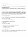
12-5 WIRING
RECOIL STARTER OPERATION
Wire as shown in the wiring diagram below. Normally, those indicatedby dotted lines are not includedin engine wiring. Lighting coil for Models EY15,.EY20 and EY28 (anoptional, not standard accessory) permits installation of an AC buzzer with
an intermediate tap.
[BREAKER POINT IGNITION TYPE]
Condenser
Ignition C o i l
2
m
3
-
n
?
m
P
v)
Magneto
Fig. 61
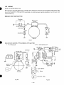
[SOLID STATE IGNITION TYPE for MODELS EY15 and EY201
1. T. I.C. (Standard)
2.
(with
P. I.T.
coil)'
lighting
BlacklYellow
Spark Plug
Buzzer Switch
""
Fig. 62
Fig. 63
- 51 -
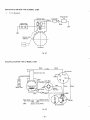
[SOLID STATE IGNITION TYPE for MODEL EY28l
c
1.
T. I.C. (Standard)
Stop Button
Ignition Coil
Spark Plug
l-
Connecter
Black
rrm
Exciter Coil
(Option)
Flywheel
Fig. 64
[ELECTRIC STARTER TYPE for MODEL EY281
Key Switch
Ignition Coil Unit
Black
S
r-----
I""
7 7 h
Battery (12V 24AH)
Starting Motor
/"-
Fig. 65
- 52 -
13. ELECTRIC SBA TBNG MOTOR (OPVBO for EV28 ONLY)
13-1 SPECIFICATIONS
Starting Motor
Part Name
Maker Denso
Nihon
Bolt
K . K.
Voltage
12v
output
0.6 kW
Weight
3.0 kg
DriveLever
Stop
Collar
Fig. 66
13-2 OPERATION
Connect the (t) side of battery to the 8 $ terminal of starting motor magnet switch.
The state of starting motor “ON” is as shown in the follow-
1
From Rectifier
Battery
ing figure:
When thekeyswitch
closedand
is putto
thecurrentflows
“ON,” the M+ circuit is
to thearrowheaddirection.
The magnet switch coil is excited, and the contact is drawn
UP.
Then the continuity is made to the starting motor, and the
pinion gear is instantaneously pushed outby the drive lever.
Thepiniongear
is engaged withthe
ring gear, andthe
Magnet Switch
engine cranking is made.
This means that the lower current flows in the M + circuit,
and in the S-+circuit larger starter current flows.
- 53 -
Fig. 67
Key Switch B
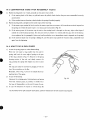
14. RECOIL STARTER DISASSEMBLY and REASSEMBLY
The recoil starter hardly has a trouble in the normal use, however, case
in it has a trouble or at thetime of lubrication, perform disassembly and reassembly in thefollowing procedures:
Tools to be used: Box spanner (spanner), Cutting pliers (pliers) and Screw driver
14-1 HOW TO DISASSEMBLE
(DType)
Starter
Remove the recoil starter from the engine with a box
Rope
spanner.
Pull the starting knob and pull out the starter rope for
30 to 40 cm.Firmly press the reel with a thumb
as
shown in Fig. 68 so that the reel should not make reverse turn ai the place where the reel notch comes to
the outlet of starter rope. Pull out the starter rope
the inside of recoil starterwith
to
a screwdriver. Then,
Notch %
'4
utilize the reel notch, and rewind it until the rotation
Starter Knob
stops in the arrowhead direction, braking the reel rotation with a thumb.
3) When removing, take out the parts in the order
Fig. 68
of the
2
numbering in Fig. 69.
1.
@-"
U typesnap ring
3
2. Thrust washer
3.
Frictionspring cover
4.
Return spring
5.
Friction spring
6.
Ratchet
5
3
Meantime, for removing the U type snap ring, nip the
shaft with cuttingpliers and push it out.
Fig. 69
-54-
b
4)
Take out the reel from the starter case as shown in Fig.
70:
In this case, slowly take out it turning the
towardleftand
right so thatthe
reel lightly
spring is removed
from the reel hook section.
If the reel is suddenly taken out, there is a fear that the
spring jumps out in the form as it is hooked, w h c h is
very dangerous,so be carefuly of it.
(If the spring jumped out, house itin the starter case as
I
instructed in Fig. 75.)
Starter Case
Finally, release andtake
outthestarterrope
Spring
tied to
both the reel side and the starting knob side.
Fig. 70
Thus, the disassembly work ends.
14-2 HOW TO REASSEMBLE (Type D)
1)
First, have thestarterrope
No.2
No.1
pass throughthestarting
knob, and tie the rope as shown in Fig. 71 No.1.
Then, have the opposite side of the rope pass through
thestarter
case andthe
reel, and tie it as shown in
Fig. 71 No.2. Then surelyhouse the end in the reel.
(In the Fig. 71 both the ropes are tied quite lightly, as
you see in figures No. 1 and No.2. Please note this is
just for the purpose of
easy understanding. Therefore,
when actually tying, tie the rope as tighteiy as possible.
Fig. 71
2) Confirm that the spring is surely set in the starter case
Outer Edge of Spring
Good
housing section, and have the spring to form so that its
Reel Hook
/
inner edge will be about 1 mm from the starter shaft
and that ithooks surely the reel hook.
Meantime, with the pliers about 10cm long spring from
the inner edge can easily be formed.
Starter
Shaft
4 c m
\
Inner Edge of Spring
Fig. 72
- 55 -
3) Before puttingthe
reel in the startercase,windthe
starter rope in the arrowhead directionas shown in Fig.
73, and at 2.5 windings take out the rope from the reel
notch. Set the reel hook to the inner end of thespring,
and put the reel in the startercase.
(At this time, confirm that the reel hook is duly set to
the spring.)
Then, hold the starter
rope as shown in Fig. 73, and
turn the reel 4 times in the arrowhead direction, When
wound up, firmly press the reel not to allow reverse
turn, and pull the starting knob. Then,
pull out from
Fig. 73
thestarter case the starter ropeutilizedforwinding,
and slowly return khe starting knob.
4) When reassembling theparts,follow
up inthe reverse
order to Fig. 69.
When putting the friction
plate in the hole for it, set
the return spring a little upward as shown in Fig. 74 so
that the friction plate can easily be put in the hole for
it.
Next, turn the friction plate in the arrowhead direction
till the position where its notch matches with the ratchet. Push firmly the friction plate to the
reel side, and
put the thrust washer and then clamp it witha U shape
snap ring.
(Clamp the U shape snap ring with cutting pliers.)
Fig. 74
t With the above, the disassembly and reassembly works end, however, there is a case that theparts are not properly re-
assembled. Therefore, for caution's sake check the function of the recoil starter following the confirmation items
described in the next page.
- 56 -
14-3 CONFIRMATION ITEMS AFTER REASSEMBLY (Type D)
1)
Pull the starting knob 2 or 3 times, and pull out the starter rope a little.
i)
If the starting knob is felt heavy t o pull and cannot be pulled, check whether the parts were reassembled correctly
as instructed.
n) If the ratchet does not function, check whether thespring is hooked properly.
2) Pull the starting knob, and pull out the starter rope all the way long.
i)
If the starter rope remains left in the reel or the starter rope does not return atall, immoderate strain is imposed on
the spring. So rewind the starter rope 1 or 2 times as per instruction in Fig. 68.
ii) If the return power of the starter rope
is weak or the starting knob is drooped on the way, inject a few drops of
mobile oil in the frictional portions.If it does not revive yet, wind it 1 or 2 times. (In this case, refer to the instructions explained in the paragraph i) above and confirm whether or not immoderate strainis imposed on the spring.)
i
i
i
) If the sound is heard that the spring is falling off, and the starter rope cannot.be wound in relay, reassemble once
again from the biginning.
14-4 HOW TO DO IN SUCH CASES!
1) In case the spring jumps out when disassembling
With thin wiremake a ring smaller than the case for
spring, and hook the outer
edge of spring on the part
of the ring as shown in Fig. 75. House it in the spring
housingsectionofthereel,andcalmlyremovethe
ring, pressing the spring with fingers so as not to come
out.
The ring can easily be removed by gouging it with the
tip of the screwdriver or the like.
Meantime, refer to Fig. 72 for not to mistake the housing direction of the spring.
2 ) In case oflubricating
Lubricate the rotating parts, frictional parts and spring
Fig. 75
with heat resistant grease, if possible, or mobile oil at
the time of disassembly or at the end of season for use.
3)
In case thedirectionofrotation
is reverse (Type B)
As this manual is for right rotation recoil starter, perform reverse work for left rotation recoil starter.
- 57 -
15. CHECKS and CORRECTIONS
P
After disassembling and cleaning the engine, check and repair, if necessary, according to the correction table. The correction
table applies whenever the engines are repaired.
It is important for the servicemen t o be familiar with the contents of this
table. Correct maintenance is recommended by observing the correction standardsspecified.
The meanings of the termsused in the correction tableare as follows:
Correction
Repair, adjustment or replacement of any engine parts.
Correction Limit
The limit on wear, damage or functional deterioration of engine parts beyond which normal engine performance cannot be expected without repairing such parts.
Use Limit
The limit beyond which parts can no longer be used in respect of performance or strength.
Standard Dimensions
The design dimensions of new parts minus tolerance.
Correction Tolerance
Tolerance on the dimensions of engine parts refinished or adjusted.
- 58 -
16. TABLES OF CORRECTIONSTANDARDS
I
ENGINE
MODEL
ITEM
Flatness ofcylinder
head
I 1
Bore
Roundness
Valveguide I.D.
Less than 0.1
EY 15
S.T.D. 63 dia.
EY 20
67 dia.
EY28
S.T.D. 75 dia.
EY15
EY20
EY 28
Cylindricity
STANDARD
SiZE
EY20
EY28
EYl5
EY 20
EY 28
0.01
Valve seat contact
width
1
1
.
Dif. between
-
rnax. & rnin.
0
+0.019
USE
LIMIT
7
0.15
0.1 5
REMARKS
0.65
1
TOOL
plate,
CORRECTION
METHOD
Correct
I
Boring
1
0.01 5
EY 15
I 1
EY15
EY20
EY 28
6.5@
I
O.D. at skirt, in
thrust direction
(incl. over size)
0 0.25
0.5
C
S.T.D.66.98dia.
67.23 dia.
I
I
Width of ring
groove
0.1 5
0.1 5
-0.1
-0.1
0
- 0.02
Oil
"*
A t middle
portion
Cylinder
gauge
Replace
Micrometer
Replace
I
Oil 30
I
I
+0.060
Top 1.5
1
+0.022
S.T.D. 74.98 dia.
B
75.23 dia.
C
75.48 dia.
EY28
EY15
EY2O
2.5
S.T.D.62.98 dia.
B
63.23 dia.
EY15
I
Correct
1.2 -1.5
I
Replace
0.1 5
t0.040
+0.002
-0.009
14 dia.
+0.002
Piston pin hole
16 dia.
Clearance between
piston and cylinder
Clearance between
pisition ring and
ring groove
20
- 0.009
EY15
EY20
0.020-0.059
EY 28
0.040-0.079
0.035
0.035
Max. cylin-
-
0.025
thrust direction
Micrometer
Replace
0.090-0.135
0.060-0.1 05
0.010-0.065
To P
EY
0.050-0.095
0.010-0.055
0.010-0.065
- 59 -
0.1 5
0.1 5
Replace
d
Clearance between
pirition ring and
ring groove
1 1
EY15
EY20
EY28
EY28
TEY15
10-0.029
0.01 0-0.065
0.01 0-0.065
0.15
0.1 5
-0.009-0.010
0.06L
0.06L
1.5
1.5
-0.1
-0.1
- 0.04
-0.04
0.1
0.1
EYZO
I 1
nd
LIMIT
REMARKS
I
0.050-0.090
Ring gap
1
Ring
I 1
dia.
EY28
Large end I.D.
Clearance
between
rad large end I.D.
and crankpin
Oil
2nd
2;
Oil
2.8
T
0.20
-
0.40
0.05
-
0.25
0.1
-
0.3
Top 1.5
2nd 1.5
Oil 3.0
4.010-
24 dia.
EY
2620
die.
EY 28
28 dia.
I
0
-
-0.008
EY15
Parallelism between
large end
and
small end bores
Replace
Replace
Micrometer
Replace
I
1 1
EY 15
EY28
EY20
-
0.3
0.05
Distance between
large end and
small end bores
- 60
-
Replace
gauge,
0.08
0.08
Cylinder
gauge
Replace
0.1 2
0.12
Cylinder
gauge.
Micrometer
Replace
1 .o
1 .o
0.1
0.1
0.15
100
Cylinder
0.2
16 dia.
0.1
EY 28
Feeler
0.2
14 dia.
Small
Large end side
clearance
1
Cylinder
0.037-0.063
0.020-0.046
Ey15
EY20
EY28
gauge.
Micrometer
0.030
+0.013
EY15
EY20
Clearance between
small end I.D.
and pinstonpin
Replace
I
EY15
EY 28
Feeler
CORRECTION
METHOD
~~~
-0.050--0.070
-0.010--0.030
-0.010--0.030
14
16 dia.
TOOL
-0.090--0.110
-0.060--0.080
-0.010--0.030
TOP 2.0
2.0
011 2.8
I
I
EY28
USE
LIMIT
EY28
Fit between piston
and piston pin
width
I
Y
CORRECTI,
STANDARD
ENGINE
MODEL
TOLERANCE
Micrometer
Feeler
gauge
Test bar
and Dial
Replace
Rernachine
or Replace
Re-machine
or Replace
ITEM
lAODEL
24 die.
CORRECT1 N
LIMIT
TOLERANCE
1
EY28
EYt5
EY20
EY 28
1
28 dia.
0.1 5
Micrometer
0.5
Re-machine
or Replace
-0.020
-0.033
Less than 0.005
Micro.
meter
Crankpin O.D.
cylindricity
Less than 0.005
Micrometer
Crankpin O.D.
parallelism
Less than 0.008
Dial
wuge
Crankpin 0 . D
roundness
CORRECTION
METHOD
-0.037
-0.050
Crankpin O.D.
TOOL
Drive s. 25 die.
EY15
Mag. 8 . 25 dia.
Crankshaft
journal O.D.
Drive s. 25 die.
EY 20
Mag.s.
25 die.
- O.OO3
- 0.012
- 0.05 - 0.05
Micrometer
Replace
- 0.25
Micrometer
Replace
Micrometer
Replace
Vernier
calipers
Replace
Square
Replace
Drive s. 30 dia.
EY28
Mag. s. 30 dia.
Cam lobe height
io.1
EY20
EY15
-t
Drive s. 15 dia.
-0.01 6--0.027
Mag. s. 15 dia.
-0.05
Drive s. 25 dia.
-0.003--0.012
Mag. s. 15 die.
-0.016--0.027
Drives. 15dia.
-0.016--0.027
Mag. s. 25 dia
-0.020--0,033
Drive s. 30 dia.
-0.003--0.012
Mag. s. 25 dia.
-0.020--0.033
- 0.25
I-0.05
EY 158
Journal O.D.
EY 28D
EY28B
Free length
EY15
EY 20
EY 28
Squareness
EY15
EY 20
EY 28
37
-1.5
,,o
-61
-
1
For total
length
ITEM
1
CORRECT1
STANDARD
ENGINE
MODEL
I
N
TOLERANCE
SIZE
LIMIT
USE
LIMIT
-0.15
Clearance between
stem and guide
-
EY15
Intake
Exhaust
0.056
0.025
EYrn
EY 28
Intake
Exhaust
0.025
0.056
--
I
REMARKS
CORRECTION
METHOD
Micrometer
Replace
Cylinder
gauge
Replace
Feeler
gauge
Correct
"
0.062
0.100
0.062
0.100
0.3
0.3
At middle
blow
When cold
0.10 *0.02
Clearance between
groove and retainer
I I
I
Stem end
length
-
EY15
I
EY,5
EY2O
I
I
0.1
Intake
Exhaust 5.9
Intake6'2
Exhaust 6.4
Tntake
Exhaust
I
EY15
I
0.3
0.05
abow
0.25
0.5
0.5
Feeler
gauge
Replace
.o
-1 .o
Vernier
calipers
Replace
- 0.5
- 0.5
Vernier
calipers
Replace
0.2
0.2
1
I
-1
4.45
35.6
I
43.7
EY28
1
0.013
-
0.037
stem and guide
1 I
EY28
Spark plug
I
EY28
I
NGKBBHS
NGK BPBHS
I :;: I
1
0.013-0.043
I
EY15
Spark gap
I I
0.6
-
1
0.7
I
1
EY15
Spark timing
t 5"
23'before T.D.C.
EY
EY2028
Point opening
Adjust or
replace
Feeler
f
0.05
- 62 -
f
0.1
Timing
tester
breaker
spanner
Adjust
Adjust
tTEM
Max. output
Continuous Rated
Output
MODEL
HP/rpm
CORRECTION LIMIT
EYISD
EYl5B
EY2OD
EY28D
EY 288
3.514000
3.512000
5.0/4000
7.514000
7.512000
Below 110% of rated output
EY15D
EYl58
EY2OD
EY 28D
EY28B
2.713600
2.711 800
3.513600
5.513600
5.511 800
ITEM
Fuel Consumption
ITEM
Lubricant
Consumption
ITEM
liter/hr
REMARKS
MODELCORRECTION PRECISENESS
EY15
EY20
EY28
1.1
1.2
2.7
MODEL
cc/hr
USE LIMIT cc/hr
EY15
10
50
EY20
EY28
15
60
MODEL
Q
EY15
EY20
0.6
EY28
0.85
CORRECTION PROCEDURE
135%of t h e standard value and up
3600 rPm at cOnthuOuS rated Output
REMARKS
REMARKS
c
Fixed quantity
of Lubricant
*Use the SC or higher grade engineoil.
ITEM
MODEL
EY15
Specified Lubricant
Qualiw
r
I
Comparison between oil viscosity temparature
and
?,I,!,
Single
grade
EY20
#30
EY28
I I II
Multigrade
I
-20
#40.
I
I
10
I
20
30
- 63 -
When the peripheral temparature i s more
than 4OoC.use the oil of vismsitv and
quality
fitied
to
t h e local
conditibns.
II
~~.
1OW-30
0
II
I
When the peripheral temparature is
below -2OoC, use the oil of viscosity
and quality fitted tothe local conditions.
The oil consumption i s apt t o increase,
when used under high peripheral temparature, so it i s necessary t o check every
day.
4OoC
If quality and quantity of the engine oil become lower or less, burning might be caused
1
I
1
I
-10
1
REMARKS
ITEM
FREOUEMCYOFOILCHANGE
EY15
EY 20
EY 28
Oil C h a w
ITEM
First time: Change oil after 20 houn operation.
Second Time and Thereafter: Change oil every 50 hours operation.
MODEL
kglcm'lrpm
EY15
514 00
CORRECTION LIMIT
70% of normal value
and down
Cylinder p r o w r e
EY2O
EY 28
ITEM
1200
EY 15B
600
EYZOD
1200
EY28D
1200
EY28B
600
I
MODEL
I
EY15
SO170
EY 28
I Ff;: 1
EY28
-
TOOL
I
REMARKS
Torque wrench
Torque wrench
200
1
600- 650
170- 190
120
-
230
- 270
Smrk Plug
EY28
I
115
EY15
I
ft-lb
REMARKS
260
twin
.WlfS
.
I
- 230
-
EY28
220
Connectin0 rod
Magneto clamp
nuts
kgem
190
EY 20
Cylinder haad
bolts
I I
TOOL
rpm
EY 15D
ITEM
Reference value
Crankshaft Rev.
Pressure gauge
61400
MODEL
Mn. acderating
molution
REMARKS
TOOL
I
Toraue wrench
1
150
wrench
Torque
-64-
-_
17. MAINTENANCE and STORING
&
-
m e following maintenance jobs apply when the engine is operated correctly under normal conditions. The indicated maintenance intervals are byno means guarantees for maintenance free operations during these intervals.
For example, if the engine is operated in extremely dusty conditions, theair cleaner should be cleaned every day instead of
every 50 hours.
17-1DAILY
CHECKS and MAINTENANCE
I
I
I
I
Checks and maintenance
Reasons for requiring them
The governor linkage is especially susceptible to dust.
Remove dust from whatever parts which
accumulated dust.
Not only wasteful but also dangerous
Check external fuelleakage. If any, retighten or
replace.
Check screw tightening.If any loose one is found,
Loose screws and nuts will result in vibration
re-tighten.
accidents.
Check oil level in crankcase and add upas necessary.
If the engine is operated without sufficientoil,it will
17-2EVERY
20 HOURS CHECKS and MAINTENANCE
I
1
I
Reasons for requiring them
Checks and maintenance
To remove run-in wear particles
Change crankcase oil.
17-3EVERY
50 HOURS(10DAYS)
CHECK and MAINTENANCE
Checks and maintenance
Change crankcase oil.
Contaminated oil accelerates wear.
Clean air cleaner.
Clogged air cleaner harms engineoperation.
Check spark plug.I f contaminated, wash in
Output power is reduced and starting
gasoline or polish with emery paper.
is made difficult.
17-4EVERY100
I
I
Reasons for requiring them
- 200 HOURS (MONTHLY) CHECKS and MAINTENANCE
Checks and maintenance
Clean fuel
filter
and
fuel
tank.
I
1
~~
~
~~~
Reasons for requiringthem
The
engine
will be out of order.
I
Clean contact breaker points.
The engine output drops.
- 65 -
17-5 EVERY
500- 600 HOURS(SEMIANNUAL)
CHECKS and MAINTENANCE
Checks and maintenance
Remove cylinder head andremove carbon
Reasons for requiring them
The engine w
l
ibe out of order.
deposit.
Disassemble and clean carburetor.
77-6 EVERY 1000HOURS
(YEARLY) CHECKS and MAINTENANCE
Reasons for requiring them
Checks and maintenance
Perform overhauls, clean, correct
or replace
The engine output drops andbecome out of order.
parts.
Change piston rings.
Replace fuel pipe once
year.
aTo
prevent from danger
caused
the
by
fuel
leakage.
1
17-7 PREPARATION for LONG ABEYANCE
1) Perform the above 17-1 and 17-2 maintenance jobs.
2) Drain fuel from the fuel tankand carburetor float chamber.
3) To prevent rust in the cylinder bore, apply oil through the spark plug hole and turn the crankshaft several turns by
h d . Reinstall the plug.
4)
Turn the starting pulley by hand and leave it where the resistance is the heaviest.
5 ) Clean the engine outside with oiled cloth.
6 ) Put a vinyl or other cover over the engine and store the engine in dry place.
- 66 -
Industrial
Engines