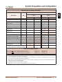
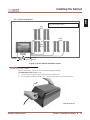
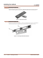
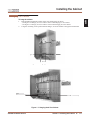
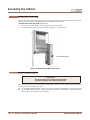
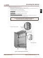
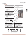
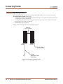
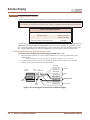
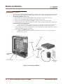
1
1. Installing the Cabinet
2. PCB Installation
•
•
•
•
To use the IntraMail enhancements provided by software versions 03.2*.** and
higher, you must use the NEC IntraMail Utility version 1.2 to upgrade your IntraMail CompactFlash card. If you don’t upgrade your card, the new features will not
be available.
If upgrading from version 3 software prior to 03.10.08 using telephone programming, you must reprogram the options in 1808-IntraMail Subscriber Mailbox
Options, 8005-IntraMail Master Mailbox Options, and 8006-IntraMail Routing Mailboxes after the upgrade.
To avoid having to reprogram the above options, use the latest version of the
DS1000/2000 System Administrator to backup and restore the site database.
Go to http://ws1.necii.com/ds2000 to download the latest versions of the Update
Utility, IntraMail Utility, System Administrator, and system software.
3. Installing Extensions
and Trunks
4. Optional
Equipment
5. Maintenance
Options and SMDR
6. Specifications
and Parts
Hardware Manual
(03.2*.**)
For additional resources, visit our Technical Support site on the web at http://ws1.necii.com/ds2000.
This manual has been developed by NEC Unified Solutions, Inc. It is intended for the use of its customers and service
personnel, and should be read in its entirety before attempting to install or program the system. Any comments or suggestions
for improving this manual would be appreciated. Forward your remarks to:
NEC Unified Solutions, Inc.
4 Forest Parkway
Shelton, CT 06484
www.necunifiedsolutions.com
Nothing contained in this manual shall be deemed to be, and this manual does not constitute, a warranty of, or representation
with respect to, any of the equipment covered. This manual is subject to change without notice and NEC Unified Solutions,
Inc. has no obligation to provide any updates or corrections to this manual. Further, NEC Unified Solutions, Inc. also reserves
the right, without prior notice, to make changes in equipment design or components as it deems appropriate. No
representation is made that this manual is complete or accurate in all respects and NEC Unified Solutions, Inc. shall not be
liable for any errors or omissions. In no event shall NEC Unified Solutions, Inc. be liable for any incidental or consequential
damages in connection with the use of this manual. This document contains proprietary information that is protected by
copyright. All rights are reserved. No part of this document may be photocopied or reproduced without prior written consent
of NEC Unified Solutions, Inc.
©2005 by NEC Unified Solutions, Inc. All Rights Reserved.
Printed in U.S.A.
Table of Contents
Table of Contents
Section 1: Installing the Cabinet . . . . . . . . . . . . . . . . . . . . . . . . . . . . . . . . . . . . . . . . . . . . . . 1-1
System Preparation and Configuration. . . . . . . . . . . . . . . . . . . . . . . . . . 1-1
Unpacking. . . . . . . . . . . . . . . . . . . . . . . . . . . . . . . . . . . . . . . . . . . . . . . . . . . . . . . . . 1-1
Before Installing . . . . . . . . . . . . . . . . . . . . . . . . . . . . . . . . . . . . . . . . . . . . . . . . . . . . 1-1
Site Requirements. . . . . . . . . . . . . . . . . . . . . . . . . . . . . . . . . . . . . . . . . . . . . . . . . . . 1-1
Expanded Database . . . . . . . . . . . . . . . . . . . . . . . . . . . . . . . . . . . . . . . . . . . . . . . . . 1-2
DS2000 Default Numbering . . . . . . . . . . . . . . . . . . . . . . . . . . . . . . . . . . 1-2
Automatic Slot Configuration . . . . . . . . . . . . . . . . . . . . . . . . . . . . . . . . . . . . . . . . . 1-4
System Configuration. . . . . . . . . . . . . . . . . . . . . . . . . . . . . . . . . . . . . . . . . . . . . . . . 1-4
DS2000 Default Configuration . . . . . . . . . . . . . . . . . . . . . . . . . . . . . . . . 1-4
DS2000 Configuration Guidelines. . . . . . . . . . . . . . . . . . . . . . . . . . . . . . 1-5
DS2000 Load Factor Calculations . . . . . . . . . . . . . . . . . . . . . . . . . . . . . . 1-6
Installing the Cabinet . . . . . . . . . . . . . . . . . . . . . . . . . . . . . . . . . . . . . . . 1-8
Planning the Installation . . . . . . . . . . . . . . . . . . . . . . . . . . . . . . . . . . . . . . . . . . . . . . 1-8
Removing the Cover. . . . . . . . . . . . . . . . . . . . . . . . . . . . . . . . . . . . . . . . . . . . . . . . . 1-9
Unpacking the Wall Mount Bracket. . . . . . . . . . . . . . . . . . . . . . . . . . . . . . . . . . . . 1-10
Mounting the Wall Mount Bracket. . . . . . . . . . . . . . . . . . . . . . . . . . . . . . . . . . . . . 1-10
Hanging the Cabinet . . . . . . . . . . . . . . . . . . . . . . . . . . . . . . . . . . . . . . . . . . . . . . . . 1-11
Grounding the Cabinet . . . . . . . . . . . . . . . . . . . . . . . . . . . . . . . . . . . . . 1-12
Removing the Right Side Panel . . . . . . . . . . . . . . . . . . . . . . . . . . . . . . . . . . . . . . . 1-12
Attaching the Ground Wires. . . . . . . . . . . . . . . . . . . . . . . . . . . . . . . . . . . . . . . . . . 1-12
RFI Suppressor Assemblies . . . . . . . . . . . . . . . . . . . . . . . . . . . . . . . . . . 1-14
Installing RFI Suppressor Assemblies . . . . . . . . . . . . . . . . . . . . . . . . . . . . . . . . . . 1-14
Power Supply Installation. . . . . . . . . . . . . . . . . . . . . . . . . . . . . . . . . . . 1-15
Installing the Power Supply . . . . . . . . . . . . . . . . . . . . . . . . . . . . . . . . . . . . . . . . . . 1-15
Section 2: PCB Installation . . . . . . . . . . . . . . . . . . . . . . . . . . . . . . . . . . . . . . . . . . . . . . . . . . . 2-1
PCB Location . . . . . . . . . . . . . . . . . . . . . . . . . . . . . . . . . . . . . . . . . . . . . . 2-1
Where to Install the PCBs . . . . . . . . . . . . . . . . . . . . . . . . . . . . . . . . . . . . . . . . . . . . 2-1
Installing PCBs. . . . . . . . . . . . . . . . . . . . . . . . . . . . . . . . . . . . . . . . . . . . . 2-2
Central Processing Unit (CPU) PCB . . . . . . . . . . . . . . . . . . . . . . . . . . . . . . . . . . . . 2-2
Installing the CPU . . . . . . . . . . . . . . . . . . . . . . . . . . . . . . . . . . . . . . . . . . 2-2
Digital Station (16DSTU) PCB . . . . . . . . . . . . . . . . . . . . . . . . . . . . . . . . . . . . . . . . 2-3
Analog Station (8ASTU and 4ASTU) PCBs . . . . . . . . . . . . . . . . . . . . . . . . . . . . . . 2-5
16-Port Analog Station (16ASTU) PCB . . . . . . . . . . . . . . . . . . . . . . . . . . . . . . . . . 2-6
Analog Trunk (8ATRU and 4ATRU) PCBs . . . . . . . . . . . . . . . . . . . . . . . . . . . . . . 2-7
T1 Trunk PCB . . . . . . . . . . . . . . . . . . . . . . . . . . . . . . . . . . . . . . . . . . . . . . . . . . . . . 2-8
T1 PCB Leds . . . . . . . . . . . . . . . . . . . . . . . . . . . . . . . . . . . . . . . . . . . . . 2-11
T1 Programming Summary . . . . . . . . . . . . . . . . . . . . . . . . . . . . . . . . . . 2-12
Connecting Blocks . . . . . . . . . . . . . . . . . . . . . . . . . . . . . . . . . . . . . . . . 2-14
Working With 8-Pin Jacks . . . . . . . . . . . . . . . . . . . . . . . . . . . . . . . . . . . . . . . . . . . 2-14
Punching Down the Cables . . . . . . . . . . . . . . . . . . . . . . . . . . . . . . . . . . . . . . . . . . 2-14
Making Your Own Cables . . . . . . . . . . . . . . . . . . . . . . . . . . . . . . . . . . . . . . . . . . . 2-14
DS2000 Hardware Manual
Table of Contents ◆ i
Table of Contents
Section 3: Installing Extensions and Trunks . . . . . . . . . . . . . . . . . . . . . . . . . . . . . . . . . . . . . . 3-1
Connecting Extensions . . . . . . . . . . . . . . . . . . . . . . . . . . . . . . . . . . . . . . 3-1
Connecting Extensions . . . . . . . . . . . . . . . . . . . . . . . . . . . . . . . . . . . . . . . . . . . . . . . 3-1
Connecting Trunks . . . . . . . . . . . . . . . . . . . . . . . . . . . . . . . . . . . . . . . . . 3-2
Connecting Analog Trunks. . . . . . . . . . . . . . . . . . . . . . . . . . . . . . . . . . . . . . . . . . . . 3-2
Power Up and System LEDs. . . . . . . . . . . . . . . . . . . . . . . . . . . . . . . . . . . 3-3
Power-Up . . . . . . . . . . . . . . . . . . . . . . . . . . . . . . . . . . . . . . . . . . . . . . . . . . . . . . . . . 3-3
Finishing the Installation . . . . . . . . . . . . . . . . . . . . . . . . . . . . . . . . . . . . 3-5
Reinstalling the Side Panel. . . . . . . . . . . . . . . . . . . . . . . . . . . . . . . . . . . . . . . . . . . . 3-5
Reinstalling the Front Cover . . . . . . . . . . . . . . . . . . . . . . . . . . . . . . . . . . . . . . . . . . 3-6
Section 4: Optional Equipment . . . . . . . . . . . . . . . . . . . . . . . . . . . . . . . . . . . . . . . . . . . . . . . 4-1
External Paging . . . . . . . . . . . . . . . . . . . . . . . . . . . . . . . . . . . . . . . . . . . . 4-1
Installing External Paging . . . . . . . . . . . . . . . . . . . . . . . . . . . . . . . . . . . . . . . . . . . . 4-1
External Paging Relay Control. . . . . . . . . . . . . . . . . . . . . . . . . . . . . . . . . . . . . . . . . 4-2
Connecting the Relay for External Paging Control . . . . . . . . . . . . . . . . . 4-2
Programming the Relay for External Paging Control . . . . . . . . . . . . . . . 4-3
Additional Programming . . . . . . . . . . . . . . . . . . . . . . . . . . . . . . . . . . . . . 4-3
Music Source. . . . . . . . . . . . . . . . . . . . . . . . . . . . . . . . . . . . . . . . . . . . . . 4-4
Installing a Music Source . . . . . . . . . . . . . . . . . . . . . . . . . . . . . . . . . . . . . . . . . . . . . 4-4
Programming Background Music. . . . . . . . . . . . . . . . . . . . . . . . . . . . . . . . . . . . . . . 4-4
Programming Music on Hold . . . . . . . . . . . . . . . . . . . . . . . . . . . . . . . . . . . . . . . . . . 4-4
Power Failure Telephone . . . . . . . . . . . . . . . . . . . . . . . . . . . . . . . . . . . . 4-5
Power Failure Cut-Through . . . . . . . . . . . . . . . . . . . . . . . . . . . . . . . . . . . . . . . . . . . 4-5
DSS Console . . . . . . . . . . . . . . . . . . . . . . . . . . . . . . . . . . . . . . . . . . . . . . 4-6
Installing a DSS Console . . . . . . . . . . . . . . . . . . . . . . . . . . . . . . . . . . . . . . . . . . . . . 4-6
Programming DSS Consoles . . . . . . . . . . . . . . . . . . . . . . . . . . . . . . . . . . . . . . . . . . 4-6
2-OPX Module. . . . . . . . . . . . . . . . . . . . . . . . . . . . . . . . . . . . . . . . . . . . . 4-8
Installing the 2-OPX Module . . . . . . . . . . . . . . . . . . . . . . . . . . . . . . . . . . . . . . . . . . 4-8
Programming 2-OPX Modules. . . . . . . . . . . . . . . . . . . . . . . . . . . . . . . . . . . . . . . . . 4-9
Wall Mounting the 2-OPX Module . . . . . . . . . . . . . . . . . . . . . . . . . . . . . . . . . . . . 4-10
Wall-Mount Kit . . . . . . . . . . . . . . . . . . . . . . . . . . . . . . . . . . . . . . . . . . . 4-11
Installing the Wall-Mount Kit . . . . . . . . . . . . . . . . . . . . . . . . . . . . . . . . . . . . . . . . 4-11
Wall-Mounting a Key Telephone. . . . . . . . . . . . . . . . . . . . . . . . . . . . . . . . . . . . . . 4-11
Desk Stand . . . . . . . . . . . . . . . . . . . . . . . . . . . . . . . . . . . . . . . . . . . . . . 4-13
Using the Desk Stand . . . . . . . . . . . . . . . . . . . . . . . . . . . . . . . . . . . . . . . . . . . . . . . 4-13
REJ Recording Jack . . . . . . . . . . . . . . . . . . . . . . . . . . . . . . . . . . . . . . . . 4-14
Installing the REJ Recording Jack . . . . . . . . . . . . . . . . . . . . . . . . . . . . . . . . . . . . . 4-14
Keyset Self Test . . . . . . . . . . . . . . . . . . . . . . . . . . . . . . . . . . . . . . . . . . 4-16
Testing the Keyset . . . . . . . . . . . . . . . . . . . . . . . . . . . . . . . . . . . . . . . . . . . . . . . . . 4-16
Section 5: Maintenance Options and SMDR . . . . . . . . . . . . . . . . . . . . . . . . . . . . . . . . . . . . . . 5-1
Backing Up Site Data . . . . . . . . . . . . . . . . . . . . . . . . . . . . . . . . . . . . . . . 5-1
PC Card Data Base Compatibility . . . . . . . . . . . . . . . . . . . . . . . . . . . . . . . . . . . . . . 5-1
Backing Up Site Data with a PC Card . . . . . . . . . . . . . . . . . . . . . . . . . . . . . . . . . . . 5-1
ii ◆ Table of Contents
DS2000 Hardware Manual
Table of Contents
PC Card Backup Error Messages . . . . . . . . . . . . . . . . . . . . . . . . . . . . . . . . . . . . . . . 5-2
Restoring Site Data. . . . . . . . . . . . . . . . . . . . . . . . . . . . . . . . . . . . . . . . . 5-4
Restoring Site Data from a PC Card. . . . . . . . . . . . . . . . . . . . . . . . . . . . . . . . . . . . . 5-4
PC Card Restore Error Messages . . . . . . . . . . . . . . . . . . . . . . . . . . . . . . . . . . . . . . . 5-4
Loading New System Software . . . . . . . . . . . . . . . . . . . . . . . . . . . . . . . . 5-5
Loading System Software from a PC Card . . . . . . . . . . . . . . . . . . . . . . . . . . . . . . . 5-5
SMDR. . . . . . . . . . . . . . . . . . . . . . . . . . . . . . . . . . . . . . . . . . . . . . . . . . . . 5-6
Installing SMDR. . . . . . . . . . . . . . . . . . . . . . . . . . . . . . . . . . . . . . . . . . . . . . . . . . . . 5-6
Programming SMDR . . . . . . . . . . . . . . . . . . . . . . . . . . . . . . . . . . . . . . . . . . . . . . . . 5-6
Testing the Connection. . . . . . . . . . . . . . . . . . . . . . . . . . . . . . . . . . . . . . . . . . . . . . . 5-7
Checking the System’s Serial Port Settings . . . . . . . . . . . . . . . . . . . . . . . . . . . . . . . 5-7
Modem Installation. . . . . . . . . . . . . . . . . . . . . . . . . . . . . . . . . . . . . . . . . 5-8
Installing a Modem. . . . . . . . . . . . . . . . . . . . . . . . . . . . . . . . . . . . . . . . . . . . . . . . . . 5-8
Making Your Own Data Cables . . . . . . . . . . . . . . . . . . . . . . . . . . . . . . . . 5-9
System Reset . . . . . . . . . . . . . . . . . . . . . . . . . . . . . . . . . . . . . . . . . . . . 5-10
Resetting Your System . . . . . . . . . . . . . . . . . . . . . . . . . . . . . . . . . . . . . . . . . . . . . . 5-10
Section 6: Specifications and Parts . . . . . . . . . . . . . . . . . . . . . . . . . . . . . . . . . . . . . . . . . . . . 6-1
Specifications . . . . . . . . . . . . . . . . . . . . . . . . . . . . . . . . . . . . . . . . . . . . . 6-1
Parts List . . . . . . . . . . . . . . . . . . . . . . . . . . . . . . . . . . . . . . . . . . . . . . . . . 6-6
Index . . . . . . . . . . . . . . . . . . . . . . . . . . . . . . . . . . . . . . . . . . . . . . . . . . . . . . . . . . . . . . . . .Index-1
DS2000 Hardware Manual
Table of Contents ◆ iii
Table of Contents
iv ◆ Table of Contents
DS2000 Hardware Manual
System Preparation and Configuration
Section 1: Installing
the Cabinet
System Preparation and Configuration
System Preparation and Configuration
Unpacking
Unpack the equipment and check it against your equipment lists. Inspect for physical damage. If you are not
sure about a component’s function, review the Product Description Manual. Contact your Sales Representative if you have additional questions.
Have the appropriate tools for the job on hand, including: a test set, a punch down tool and a digital voltmeter.
Before Installing
Make sure you have a building plan showing the location of the common equipment, extensions, the telco
demarcation and earth ground. In addition, the installation site must meet the requirements outlined in the
Standard Practices Manual.
Site Requirements
The common equipment is contained in the wall-mounted Main Equipment Cabinet. Choose a central location
for the cabinet that allows enough space for the equipment — and provides enough room for you to comfortably
work. Figure 1-1 4 Slot Cabinet Installation Layout on page 1-8 and Figure 1-2 8 Slot Cabinet Installation
Layout on page 1-9 show you about how much space your system requires.
DS2000 Hardware Manual
Section 1: Installing the Cabinet ◆ 1-1
1
System Preparation and Configuration
Expanded Database
The Expanded Database is a new database method that provides database records (memory) for all
possible extensions, trunks, Hunt Groups, Ring Groups, and Voice Mail ports. This new capability
allows for:
●
Automatic Slot Configuration.
●
Simplified installation of Voice Mail, Hunt Groups, and Ring Groups.
●
Support for built-in UltraMail and IntraMail Voice Mail
●
Introduction of the DS-Series PC Program.
To understand the Expanded Database, you’ll need to keep track of three things: port, station (or
trunk) number, and extension number.
●
Port
The port is where the device you are programming connects to the system. For example, each
16DSTU PCB has 16 ports which can connect up to 16 digital telephones. Ports are numbered
consecutively for each slot, and only exist when you plug in the PCB to which the device
should connect.
●
Station Number and Trunk Number
The station or trunk number is the element in software that keeps track of the connected
devices’s programming. Station and trunk numbers (and associated database records) exist for
all possible devices you can connect to the system, even if you don’t have any ports installed
to connect them. You can’t call station and trunk numbers directly - you need the associated
extension numbers to do that (see below).
●
Extension Numbers
Extension numbers allow you to access the stations and trunks. By default, each station and
trunk number has an extension number assigned to it. You can change these assignments if
you want to.
- Digital station ports have primary and secondary station numbers. The primary station’s
extension number is used to call the device connected to the port. The secondary station’s
extension number calls the second channel on 2-channel devices such as 2-OPX Modules
and Digital VANGARD Voice Mail ports.
DS2000 Default Numbering
Here is how the ports, station numbers, trunk numbers, and extension numbers are initially set up.
Default Numbering in DS2000
Stations (Telephones)
Station
1
Unassigned
Total Station Ports
•
Station Numbers
Extension Numbers
1-96
300-395
32
97-128
396-427
128
-
-
To find out the default extension number for any station number, add 299 to the station number.
- For example, station number 1 uses extension number 300 (1 + 299).
Trunks
Trunk Ports
Total Trunk Ports
•
Ports
Set by installed PCB
Ports
Trunk Numbers
Extension Numbers
Set by installed PCB
1-64
101-164
64
-
-
To find out the default extension number for a trunk number, add 100 to the trunk number.
- For example, trunk number 1 uses extension number 101 (1 + 100).
1-2 ◆ Section 1: Installing the Cabinet
DS2000 Hardware Manual
System Preparation and Configuration
Default Numbering in DS2000
Voice Mail Stations
UCD Groups
Ring Groups
Station Numbers
Extension Numbers
201-208
500-507
Total Groups
UCD Group Master Extension Numbers
8
700-707
Total Groups
Ring Group Master Extension Numbers
8
600-607
1 Available
for digital station port secondary station numbers. These are used for the second channels on 2-OPX
Modules and Digital VANGARD Voice Mail.
The following table shows the port capacity of each DS2000 PCB.
DS2000 PCB Port Capacities
PCB
Description
Port Capacity
16DSTU PCB
16 Digital Station PCB
16 (1-16)
4ASTU PCB
4 Analog Station PCB
4 (1-4)
8ASTU PCB
8 Analog Station PCB
8 (1-8)
4ATRU PCB
4 Analog Trunk PCB
4 (1-4)
8ATRU PCB
8 Analog Trunk PCB
8 (1-8)
T1 PCB
T1/E1 PCB
24 (1-24) when enabled for T1
30 (1-30) when enabled for E1
Station PCBs
Trunk PCBs
Since the Expanded Database maintains database records for all extensions and trunks, you have
the option of using Program 9902 - Set Up Stations (DS2000) and Program 9903 - Set Up
Trunks (DS2000) to assign a station and a trunk PCB to the same slot. When you plug in an ASTU
or DSTU PCB into the slot, the ports on the PCB access the associated station numbers. If you
remove that PCB and plug an ATRU in its place, the ports on the ATRU PCB access the associated
trunk numbers. Refer to the Software Manual on the System Document CD that came with your system for more.
DS2000 Hardware Manual
Section 1: Installing the Cabinet ◆ 1-3
1
System Preparation and Configuration
Automatic Slot Configuration
Automatic Slot Configuration automatically sets up station and trunk PCBs when you initially
power up the system. This simplifies installation because you no longer have to use system programming to activate station and trunk PCBs after you plug them in.
Here’s how Automatic Slot Configuration works:
With power off, install your station and trunk PCBs.
With the system powered down, install the station and trunk PCBs from left to right in the
order you want your extension and trunk numbers set up.
- Be sure to install a 16DSTU (16 Digital Station) PCB in the first slot (CN1).
- You don’t have to group your station and trunk PCBs together, although it may be more
convenient to do so. For example, when setting up a 16x32 system, you can install the 2nd
DSTU PCB and your two ATRU PCBs in any slot, in any order. Automatic Slot Configuration will properly handle the numbering.
●
Power up the system.
On power up, the system scans the PCBs from left to right and sets up the extension and trunk
numbering as follows.
- Extension numbers will begin with 300 in the first slot and increment from left to right.
- Trunk numbers will begin with 101 (starting from the first installed ATRU PCB) and will
also increment from left to right.
- For example, in a 16x32, the numbering will be:
1st 16DSTU PCB = Extensions 300-315.
2nd 16DSTU PCB = Extensions 316-331.
1st 8ATRU PCB = Trunks 101-108.
2nd 8ATRU PCB = Trunks 109-116.
●
System Configuration
DS2000 Default Configuration
Automatic Slot Configuration automatically sets up your system’s PCBs when you initially power up the system. There is no longer a factory-installed default configuration, and you don’t have to use system programming
to activate PCBs after you plug them in. Remember, you should always plug a 16DSTU PCB into slot CN1.
To take full advantage of all the new features and enhancements in software version 03.**.**, always use the
latest PCB versions.
1-4 ◆ Section 1: Installing the Cabinet
DS2000 Hardware Manual
System Preparation and Configuration
DS2000 Configuration Guidelines
The total number of components you can install and connect depends on power supply capacity and the System Load Factor. Review the DS2000 Configuration Guidelines table below and DS2000 Load Factor Calculations on page 1-6 when configuring your system.
DS2000 Configuration Guidelines
4 Slot Cabinets
• Do not install more than 2 16DSTU PCBs under any circumstances.
• The first 16DDSTU PCB you install must be in the first slot (CN1).
• Maximum configuration is 112 ports.
• The total of all extensions and trunks cannot exceed 112.
• Always use the System Load Factor table to check your system configuration.
8 Slot Cabinets
• Do not install more than 2 16DSTU PCBs for each power supply. (Install your power supplies in the
following order: slot CN101, slot CN103, slot CN102.)
• The first 16DSTU PCB you install must be in the first slot (CN1).
• The total of all extensions and trunks installed cannot exceed 112.
• Maximum configuration is 112 ports.
• Always use the System Load Factor table to check your system configuration.
DS2000 Hardware Manual
Section 1: Installing the Cabinet ◆ 1-5
1
System Preparation and Configuration
DS2000 Load Factor Calculations
The combination of trunks, extensions, 2-OPX Modules and DSS Consoles you can connect to your DS2000
system may be limited by the System Load Factor. Use the DS2000 System Load Factor Calculations chart
on the next page to verify your system’s configuration. When entering data on the chart, for each installed
item make entries for each Load Type. There are two Load Types to consider: 5 VDC and 40 VDC.
To check your system configuration:
1. Indicate the quantity for each PCB, DSS Console, and 2-OPX Module installed in the Qty column.
The number of keysets and single line sets does not affect the System Load Factor.
2. For each item for each Load Type, multiply the Qty times the Load and enter the value in the Total
column.
For example, two 16DSTU PCBs have a load of 6 for 5 VDC and 40 for 40 VDC.
3. Add up the entries in each Total column and enter the values in Item 1: Load Type Totals.
4. Review Item 2: Power Supply Capacity and determine the capacity of the power supplies installed
in your system.
5. Compare the capacities in Item 2 to your entries in Item 1. Item 1 must always be equal to or less than
the entry in Item 2.
!! Important !!
Do not operate your system if the total for either Load Type
exceeds the Power Supply Capacity of your installation.
1-6 ◆ Section 1: Installing the Cabinet
DS2000 Hardware Manual
System Preparation and Configuration
DS2000 System Load Factor Calculations
Load Type
Description
CPU PCB
Qty
1
5 VDC
1
40 VDC
Load
Total
Load
Total
6
6
0
0
16DSTU PCB
3
20
4ASTU PCB
3
5
8ASTU PCB
5
8
16ASTU PCB
10
17
4ATRU PCB
4
0
8ATRU PCB
8
0
T1 PCB
8
0
UltraMail PCB (FMS)
19
0
UltraMail 2000 PCB (VMS)
0
6
Telephones (Keysets and SLTs)
0
0
110-Button DSS Console
0
2
24-Button DSS Console
0
1
2-OPX Module
0
3
Item 1: Load Type Totals
(Cannot exceed Item 2: Power Supply Capacity.)
Item 2: Power Supply Capacity
If you have one power supply installed, the capacity is:
If you have two power supplies installed, the capacity is:
If you have three power supplies installed, the capacity is:
5 VDC = 40
5 VDC = 80
5 VDC = 120
40 VDC = 48
40 VDC = 80
40 VDC = 120
Notes:
• A 4 slot cabinet can only have 1 power supply.
• An 8 slot cabinet can have up to 3 power supplies. You cannot have more than two 16DSTU PCBs per power supply, regardless of System Load Factor calculations.
• Exceeding the allowed Load Type Total (Item 1) will cause the system’s power supplies to automatically shut down
and/or cause erratic system operation.
• Total DSS Consoles installed cannot exceed 4.
• The total of all station, trunk, and UltraMail ports cannot exceed 112.
DS2000 Hardware Manual
Section 1: Installing the Cabinet ◆ 1-7
Installing the Cabinet
Installing the Cabinet
Planning the Installation
Before installing the common equipment, you should mount a Main Distribution Frame (MDF) plywood backboard in a centrally located spot. A 1/2 sheet of plywood (4’ x 4’) should be adequate for a 4 slot cabinet (see
Figure 1-1 4 Slot Cabinet Installation Layout below). A full sheet of plywood (8’ x 4’) should be adequate for
an 8 slot cabinet (see Figure 1-2 8 Slot Cabinet Installation Layout on page 1-9). Be sure to mount the backboard using suitable fasteners, taking care to adhere to standard installation practices and local codes.
The equipment cabinet requires a three-prong, dedicated 110 VAC 60 Hz circuit (NEMA 5-15 receptacle).
The AC receptacle must be within 7 feet of the cabinet’s lower left corner.
Normally, you install the extension and trunk blocks to the right of the cabinet. Telco should also install the
RJ21X to the right of the cabinet.
!! Important !!
Local codes may prohibit you from installing extensions,
trunks and optional equipment in the same blocks.
Plywood backboard
4'
80000 - 15A
Trunk
Blocks
4'
Station
Blocks
To telco
ground
To earth
ground
Station
Blocks
Note: The system will respond to telco ring signal in the
range of 40-130 VAC @ 20 Hz.
Dedicated
AC Outlet
Surge
Protector
Figure 1-1: 4 Slot Cabinet Installation Layout
1-8 ◆ Section 1: Installing the Cabinet
DS2000 Hardware Manual
Installing the Cabinet
8' X 4' Plywood backboard
80000 - 61
Note: The system will respond to telco ring signal in the
range of 40-130 VAC @ 20 Hz.
Trunk
Blocks
Station
Blocks
Station
Blocks
Dedicated
AC Outlet
Surge
Protector
To telco
ground
To earth
ground
Figure 1-2: 8 Slot Cabinet Installation Layout
Removing the Cover
80000 -
12
Before wall-mounting, remove the cover on the Main Equipment Cabinet.
To remove the cover (Figure 1-3):
1. Unscrew the two captive screws on the front of the cabinet cover.
2. Lift up slightly on the front of the cover — then gently slide the cover back to remove it.
4 Slot Cabinet Shown
Figure 1-3: Removing the Cover
DS2000 Hardware Manual
Section 1: Installing the Cabinet ◆ 1-9
1
Installing the Cabinet
Unpacking the Wall Mount Bracket
The wall mount bracket and screws (see Figure 1-4 Wall Mount Bracket below) are taped to the packing
material in the Main Equipment Cabinet box. Unpack the wall mount bracket and mounting screws.
80
00
0
-1
1
Figure 1-4: Wall Mount Bracket
Mounting the Wall Mount Bracket
80000 - 14
Mount the wall mount bracket (see Figure 1-5 Mounting the Wall Mount Bracket below) on the MDF in a
convenient location, about 12” higher than where you want the bottom of the cabinet to line up.
Figure 1-5: Mounting the Wall Mount Bracket
1-10 ◆ Section 1: Installing the Cabinet
DS2000 Hardware Manual
Installing the Cabinet
Hanging the Cabinet
To hang the cabinet:
1. Hang the Main Equipment Cabinet on the wall mount hanger as shown:
- See Figure 1-6 Hanging the 4 Slot Cabinet below when hanging a 4 slot cabinet.
- See Figure 1-7 Hanging the 8 Slot Cabinet below when hanging an 8 slot cabinet.
2. Using the remaining screws packed with the hanger, secure the cabinet to the plywood backboard.
80000 - 13
Figure 1-6: Hanging the 4 Slot Cabinet
80000 - 60
Figure 1-7: Hanging the 8 Slot Cabinet
DS2000 Hardware Manual
Section 1: Installing the Cabinet ◆ 1-11
1
Grounding the Cabinet
Grounding the Cabinet
Removing the Right Side Panel
Remove the cabinet right side panel to gain easy access to the ground lugs and system cabling. The cabinet
has two ground connections: ETH (Earth Ground) and PBXG (PBX Ground).
To remove the right side panel (Figure 1-8):
1. Remove the two screws that secure the right side panel to the cabinet.
2. Carefully slide the right side panel down until it swings clear of the cabinet.
80000 - 16
4 Slot Cabinet Shown
Figure 1-8: Removing the Right Side Panel
Attaching the Ground Wires
!! Important !!
You must connect your system to a known earth
ground according to the following instructions.
The system provides two ground terminations. Each ground connects from the system to the ground termination using 12 AWG stranded copper wire.
●
Use the ETH (Earth Ground) for safety/system ground. You must connect ETH to a known earth ground.
●
Use the PBXG (PBX Ground) if you have trunks that require telco ground (such as ground start trunks).
This ground is not required for loop start trunks.
1-12 ◆ Section 1: Installing the Cabinet
DS2000 Hardware Manual
Grounding the Cabinet
To attach the ground wires (Figure 1-9):
1. Remove the lug on the ground connection you want to connect.
2. Follow Figure 1-10 Installing RFI Suppressor Assemblies on page 1-14 and run the ground wire(s)
through the RFI Suppressor Assembly as shown.
3. Crimp ring terminals as required to the ground wires.
4. For earth ground:
Run a ground wire from the ETH lug to a known earth ground.
For PBX Ground:
Run a ground wire from the PBXG lug to the telco ground.
If your system will have a T1 Trunk PCB:
Run a 12 AWG jumper wire from the SG (Signal Ground) lug to the ETH (Earth Ground) lug.
5. Reinstall and firmly tighten the lug(s) removed in step 1 above.
!! Important !!
Do not plug in the power cord or reinstall the right side panel
until all PCB installation and cabling are complete.
Proper grounding is required.
For T1 Trunk
PCB only
To earth ground
80000 - 17-1
To telco ground
4 Slot Cabinet Shown
Figure 1-9: Attaching the Ground Wires
DS2000 Hardware Manual
Section 1: Installing the Cabinet ◆ 1-13
1
RFI Suppressor Assemblies
RFI Suppressor Assemblies
Installing RFI Suppressor Assemblies
You must install RFI Suppressor Assemblies as follows (see Figure 1-10 Installing RFI Suppressor Assemblies
below). The suppressors must be mounted inside the cabinet and as close to the appropriate PCB as possible.
●
For Ground Wires
– You must install a separate RFI assembly for the ground wire(s) in all systems.
– If your system has 2 ground wires, install them both in the same assembly.
●
For CPU Connections
– You must install a separate RFI assembly for the CPU mod jack and RS-232 cables in all systems.
– Install both cables in the same assembly.
For CPU Connections
•
Required on CPU mod jack
and RS-232 cables for all
installations.
For Ground Wires
•
Required for all installations.
Figure 1-10: Installing RFI Suppressor Assemblies
1-14 ◆ Section 1: Installing the Cabinet
DS2000 Hardware Manual
Power Supply Installation
Power Supply Installation
Installing the Power Supply
The power supply provides the DC power sources required to operate the system.
To install a power supply (Figure 1-11) (Figure 1-12):
1. Slide the power supply into the CN101 slot. See Figure 1-12 Installing the Power Supply below.
2. Using a long-shaft phillips head screwdriver, tighten the two screws that secure the power supply.
An 8 slot cabinet may require up to 3 power supplies, using slots CN101, CN102 and CN103. Refer to
System Configuration on page 1-4 for more. Install the first supply in slot CN101. Install the second supply
in slot CN103. Install the third supply in slot CN102.
Important Compatibility Guidelines
•
•
•
•
Only install Power Supply P/Ns 80005B or 80005C.
Do not install Power Supply P/Ns 80005 or 80005A.
You can mix P/Ns 80005B and 80005C in the same system.
If your system uses UltraMail or UltraMail 2000, you must
install only Power Supply P/Ns 80005C.
Figure 1-11: Power Supply
4 Slot Cabinet Shown
0-
29
00
80
Figure 1-12: Installing the Power Supply
DS2000 Hardware Manual
Section 1: Installing the Cabinet ◆ 1-15
1
Power Supply Installation
1-16 ◆ Section 1: Installing the Cabinet
DS2000 Hardware Manual
PCB Location
Section 2: PCB
Installation 2
PCB Location
PCB Location
!! Important !!
Install telephones connected to DSTU and ASTU PCBs as on-premise extensions only.
Where to Install the PCBs
Review System Configuration on page 1-4 before installing any PCBs. Always observe the System Load
Factor when configuring your system.
●
The CPU (Central Processing Unit) PCB must plug into slot CN0.
●
A 16DSTU (16 Digital Station) PCB must plug into slot CN1.
●
All other PCBs (including 16DSTU PCBs) can plug into slots CN2-CN8.
- Slots CN5-CN8 are only available with the 8 slot cabinet.
- A 4 slot cabinet can only accept two 16DSTU PCBs.
- In an 8 slot cabinet, you can have only two 16DSTU PCBs per power supply.
!! Caution !!
•
•
•
Do not plug in the CPU PCB hot (i.e., with the system power applied).
You can plug in ASTU and ATRU PCBs hot as required.
You can plug in DSTU PCBs hot provided you first disconnect the station cabling from the PCB.
DS2000 Hardware Manual
Section 2: PCB Installation ◆ 2-1
Installing PCBs
Installing PCBs
Central Processing Unit (CPU) PCB
The CPU PCB (Figure 2-1) provides:
●
The system’s central processing, stored program and memory for the customer’s site-specific data.
●
PC Interface Card.
●
Conference circuits, DTMF receivers and DTMF generators.
●
External music input and on-board synthesized music source.
●
External paging output and associated relay.
●
Real Time Clock.
●
Battery for short term (14 day) backup of the customer’s site-specific data.
Figure 2-1: CPU PCB
Installing the CPU
The CPU PCB installs in the CN0 slot in the Main Equipment Cabinet.
To install the CPU PCB (Figure 2-2) (Figure 2-3):
1. Slide the Mode Switch to the RUN position.
2. Insert the battery (Sony CR2032 or NEC P/N EX0254-0040) into the battery clips.
3. Plug the CPU into slot CN0.
80000 - 26
Refer to Section 4, Optional Equipment for instructions on
connecting the music source, External Paging, and the auxiliary relay.
Mode Switch
Battery
Figure 2-2: Setting Up the CPU
2-2 ◆ Section 2: PCB Installation
DS2000 Hardware Manual
Installing PCBs
2
4 Slot Cabinet Shown
0-
30
00
80
Figure 2-3: Installing the CPU
Digital Station (16DSTU) PCB
The 16DSTU provides the connection for 16 digital telephones. Refer to Section 3, Installing Extensions and
Trunks for wiring instructions.
To install the 16DSTU PCB (Figure 2-4) (Figure 2-5):
1. Plug the 16DSTU PCB for extensions 300-315 into slot CN1.
2. Plug in additional 16DSTU PCBs as required. See System Configuration on page 1-4 for more.
3. Set the mode switch on each installed 16DSTU PCB to RUN.
!! Important !!
•
•
In a 4 slot cabinet, you cannot install more than 2 16DSTU PCBs.
In an 8 slot cabinet, you cannot install more than 2 16DSTU PCBs per power supply.
DS2000 Hardware Manual
Section 2: PCB Installation ◆ 2-3
Installing PCBs
Mode switch
Figure 2-4: Digital Station (16DSTU) PCB
4 Slot Cabinet Shown
0-
31
00
80
Figure 2-5: Installing the 16DSTU PCB
2-4 ◆ Section 2: PCB Installation
DS2000 Hardware Manual
Installing PCBs
Analog Station (8ASTU and 4ASTU) PCBs
The 8ASTU PCB provides connection for 8 analog extensions. The 4ASTU PCB connects 4 analog extensions.
Refer to Section 3, Installing Extensions and Trunks for wiring instructions.
To install the ASTU PCB (Figure 2-6) (Figure 2-7):
1. Plug in ASTU PCBs as required. See System Configuration on page 1-4 for more.
2. Set the mode switch on each ASTU PCB to RUN.
2
Mode switch
Figure 2-6: Analog Station (ASTU) PCB
4 Slot Cabinet Shown
A
0-
31
00
80
Figure 2-7: Installing the ASTU PCB
DS2000 Hardware Manual
Section 2: PCB Installation ◆ 2-5
Installing PCBs
16-Port Analog Station (16ASTU) PCB
The 16ASTU PCB provides connection for 16 analog extensions.
To install the 16ASTU PCB (Figure 2-8) (Figure 2-9):
1. Check your system configuration to be sure you do not exceed the allowable System Load Factor.
2. Plug the 16ASTU PCB into any available slot from CN2-CN8.
You should reserve CN1 for a 16DSTU PCB.
The PCB will auto-ID when you plug it in.
3. Set the mode switch on the 16ASTU PCB to RUN.
Mode switch
Figure 2-8: 16-Port Analog Station (16ASTU) PCB
4 Slot Cabinet Shown
Figure 2-9: Installing the 16ASTU PCB
2-6 ◆ Section 2: PCB Installation
DS2000 Hardware Manual
Installing PCBs
Analog Trunk (8ATRU and 4ATRU) PCBs
The 8ATRU provides connection for 8 loop start analog trunks. The 4ATRU PCB connects 4 loop start
analog trunks. Refer to Section 3, Installing Extensions and Trunks for wiring instructions.
To install the ATRU PCB (Figure 2-10) (Figure 2-11):
1. Plug in ATRU PCBs as required. See System Configuration on page 1-4 for more.
2. Set the mode switch on each ATRU PCB to RUN.
2
Notes:
•
•
The system will respond to telco ring signal in
the range of 42-103 VAC @ 20 Hz.
Telco battery must be 44-56 VDC.
Mode switch
Figure 2-10: Analog Trunk (ATRU) PCB
4 Slot Cabinet Shown
00
32
0
80
Figure 2-11: Installing the ATRU PCB
DS2000 Hardware Manual
Section 2: PCB Installation ◆ 2-7
Installing PCBs
T1 Trunk PCB
The DS2000 T1 PCB requires system software version 03.03.00 or
higher and expanded memory CPU P/N 80025B.
The T1 Trunk PCB (Figure 2-12) provides advanced digital trunking and gives the DS2000 a maximum of
24 trunks in a single PCB slot. The available T1 trunk types include:
●
Loop Start and Ground Start (DTMF and Dial Pulse)
●
Direct Inward Dialing (DID) Wink Start and Immediate Start (DTMF and Dial Pulse)
●
E&M Tie Line Wink Start and Immediate Start (DTMF and Dial Pulse)
Notes
Although the T1 PCB can connect directly to the telco’s T1 smart jack, a separately-purchased Channel
Service Unit (CSU) between the smart jack and the T1 PCB is recommended. Additionally, your telco
may require a CSU.
●
Normally, the T1 PCB connects to the telco’s T1 smart jack or your CSU using a standard straightthrough CAT 5 cable. However, always check the documentation that came with your CSU for cabling
requirements.
●
The T1 PCB installs in any universal slot but slot 1.
●
A commercially available T1 Tester is recommended.
●
Figure 2-12: T1 Trunk PCB
To install the T1 Trunk PCB (Figure 2-13) (Figure 2-14):
1. Set jumpers CN7 and CN9 to the T1 position.
2-8 ◆ Section 2: PCB Installation
DS2000 Hardware Manual
Installing PCBs
Plug in T1 Trunk PCBs as required. See System Configuration on page 1-4 for more.
Set the mode switch on each T1 PCB to RUN.
Using a standard straight-through CAT 5 cable, connect the T1 PCB RJ48C connector to the Telco
Smart Jack or your Channel Service Unit.
Although the T1 PCB can connect directly to the telco’s T1 smart jack, a separately purchased
Channel Service Unit (CSU) between the smart jack and the T1 PCB is recommended. Additionally,
your telco may require a CSU.
2
80061 - 2
2.
3.
4.
RX1 T
RX1 R
Mode switch
CN9
TX1 T
TX1 R
T1
E1
12345678
T1 Grounding Requirements
Be sure to run a 12 AWG
jumper wire from the SG (Signal Ground) lug to the ETH
(Earth Ground) lug.
RJ48C Connector
Pinouts
CN7
T1
E1
CN9
CN7
RS232 Port
RJ48C
Connector
Telco
Smart Jack
Straight-Through
CAT 5 Cable
Figure 2-13: T1 Trunk PCB Setup
DS2000 Hardware Manual
Section 2: PCB Installation ◆ 2-9
Installing PCBs
4 Slot Cabinet Shown
0-
76
00
80
Figure 2-14: Installing the T1 Trunk PCB
2-10 ◆ Section 2: PCB Installation
DS2000 Hardware Manual
Installing PCBs
T1 PCB Leds
Port Activity (Yellow)
Off:
Flash:
All ports on PCB idle.
Port(s) busy. The faster the flash, the more
ports are busy.
PCB Running (Green)
Slow flash: T1 PCB running.
On:
T1 PCB starting.
Sync (Master) (Green)
Off:
On:
Flash:
T1 PCB is in the slave mode (i.e., getting the
clock from the connected T1 circuit).
T1 PCB is providing the master clock to the
telco and is in sync.
T1 PCB is providing the master clock but is
not in sync.
2
Loop (Slave) (Green)
Off:
On:
Flash:
T1 PCB is in the master mode (i.e., providing
the clock to the connected T1 circuit).
T1 PCB is in sync with the external clock
source (and is not providing the master clock).
T1 PCB is not in sync with the external clock
source (and is not providing the master clock).
LOS (Loss of Signal) or Red Alarm (Red)
Off:
Signal from the connected telco T1 Circuit is
present.
On:
Signal from the connected telco T1 circuit is
not present.
An LOS alarm means there is a problem upstream
from the T1 PCB.
BPV (Bi-Polar Violation) Alarm (Red)
This alarm indicates that consecutive “one” pulses
have been received in the T1 signal in error.
Off:
The telco’s T1 signal does not contain
Bi-Polar Violations.
On:
The telco’s T1 signal is in error. It contains
Bi-Polar Violations.
A BPV alarm means there is a problem upstream from
the T1 PCB.
AIS (Alarm Indication Signal) or Blue Alarm (Red)
The telco sends an AIS alarm signal to the T1 PCB if
the telco receives faulty data from another device on
its network (i.e., upstream). It sends the AIS alarm signal to the PCB instead of the faulty data it received.
Off:
AIS signal not received from telco.
On:
AIS received from telco.
An AIS alarm means there is a problem upstream
from the telco (and upstream from the T1 PCB).
Telco
Yellow (RAI or Remote Alarm Indication) Alarm (Red)
The telco sends an RAI alarm to the T1 PCB if it
detects a problem with the T1 signal received from the
installation site. The problem can come from the T1
PCB, the CSU (if any), or be caused by faulty cabling.
Off:
RAI signal not received from telco.
On:
RAI received from telco.
An RAI alarm means there is a problem downstream
from the telco (i.e., in the T1 PCB, CSU, or cabling).
CSU
T1 PCB
U pstreamfrom T1 PCB
D ownstreamfrom T1 PCB
Figure 2-15: T1 PCB LEDs
DS2000 Hardware Manual
Section 2: PCB Installation ◆ 2-11
Installing PCBs
T1 Programming Summary
For more in depth feature description and programming details, refer to the following features in the
DS1000/2000 Software Manual (P/N 80000SWG**): Direct Inward Dialing, T1 Trunking, and Tie Lines.
Basic Programming
●
1001 - Trunk Circuit Type
Set the circuit type for each T1 trunk. The available types are:
51 (Loop Start DTMF)
52 (Loop Start DP)
53 (Ground Start DTMF)
54 (Ground Start DP)
57 (DID DTMF Wink Start)
58 (DID DP Wink Start)
59 (DID DTMF Immediate Start)
60 (DID DP Immediate Start)
61 (E&M DTMF Wink Start)
62 (E&M DP Wink Start)
63 (E&M DTMF Immediate Start)
64 (E&M DP Immediate Start)
●
9904 - T1/E1 Configuration
Use this option to set parameters for the T1 PCB.
●
Clock Control
Default: T1 PCB is the clock master.
●
If a T1 PCB is connected to a telco T1 circuit, it is usually set as clock slave (i.e., uses the
telco clock source).
●
If a T1 PCB is connected to a private T1 circuit, set the clock source according to the network configuration.
Transmit Pulse Amplitude
Default: 0 (0dB), the T1 PCB is within 133’ of smart jack or CSU.
Framer Type
Default: ESF - Extended Super Frame.
Zero Suppression
Default: Enabled - B8ZS.
Number of PCM Channels
Default: 0 - All channels active. The active channels are always the lower-numbered circuits (i.e.,
an entry of 8 means that channels 1-8 are active).
Loopback
Default: 0 - No loopback options enabled.
ANI/DNIS Programming
●
1001 - Caller ID
Enter 3 to enable ANI-based Caller ID.
●
1001 - ANI/DNIS
Specify the type of ANI/DNIS Caller ID provided by your T1 trunks. The options are:
0 (None)
1 (ANI)
2 (*ANI*)
3 (*DNIS*)
4 (*ANI*DNIS)
●
l001 - ANI Delimiter
For ANI/DNIS options 2-4 above, specify the ANI delimiter (0-9, # or *).
●
1001 - Number of ANI Digits
For ANI/DNIS option 1, specify the number of digits in the ANI number.
2-12 ◆ Section 2: PCB Installation
DS2000 Hardware Manual
Installing PCBs
DID Programming (Basic)
●
1401 - Number of DID Digits
Specify the number of DID Digits (1-8) expected from the telco.
●
1402 - DID Translation Table
Set up the system’s DID routing.
Refer to your Software Manual for additional options for setting up DID Camp On and DID Overflow.
Tie Line Programming (Basic)
Refer to your Software Manual for additional options for setting up Tie Line trunk and operator access.
If you don’t have a T1 Tester, you can alternately test Tie Line operation between two T1 PCBs in the same
cabinet or facility using the cable shown below (Figure 2-16).
To T1 PCB
Latch
faces up
80061 - 3
Pin
1
2
3
4
5
6
7
8
RX1T
RX1R
TX1T
TX1R
TX1R
TX1T
RX1R
RX1T
Pin
8
7
6
5
4
3
2
1
To T1 PCB
Figure 2-16: Connecting Two T1 PCBs Together without a Telco T1 Circuit
(For Tie Line Testing)
DS2000 Hardware Manual
Section 2: PCB Installation ◆ 2-13
2
Connecting Blocks
Connecting Blocks
Working With 8-Pin Jacks
The system uses 8-pin mod jacks to connect extensions, trunks and optional equipment. Using the Installation
Cable (P/N 80892) makes it easy to connect the PCBs to standard 66M1-50 connecting blocks. These cables
have six 8-pin modular jacks on one end and are unterminated on the other. In general, each cabinet needs:
●
One 66M1-50 block and Installation Cable (P/N 80892) for extensions and optional equipment.
●
One 66M1-50 block and Installation Cable (P/N 80892) for trunks.
●
Depending on your PCB configuration and local codes, you may need an additional 66M1-50 block
and Installation Cable (P/N 80892) for optional equipment.
Punching Down the Cables
The Installation Cables have six 8-pin jacks installed on one end and are unterminated on the other. Each
8-pin jack connects 4 extensions or 4 trunks.
To punch down the cables (Figure 2-17) through (Figure 2-21):
1. For each 66M1-50 block, punch down the Installation Cable in standard color-code order.
- Use Figure 2-17 Connecting 16DSTU Digital Station and 4/8ASTU Analog Station PCBs on page 215 when connecting extensions.
- Use Figure 2-19 Connecting 4/8ATRU Trunk PCBs on page 2-17 when connecting trunks.
2. After you have punched down your cables, route them through the side of the cabinet and secure them
with the strain relief (Figure 2-20 Securing the Cables on page 2-18).
Making Your Own Cables
If you want to make your cables (instead of using Installation Cable P/N 80892), follow the pinouts in
Figure 2-21 8-Pin (RJ61X) Jack Pinouts on page 2-19.
2-14 ◆ Section 2: PCB Installation
DS2000 Hardware Manual
Connecting Blocks
PCB Location
16DSTU PCB
8ASTU PCB
2
Extensions 300-323 Shown
25-PAIR CABLE
56
3
12
RJ61X
BLOCK
TERM
COLOR
CODE
1
1
2
3
4
5
6
7
8
WHT-BLU
BLU-WHT
WHT-ORN
ORN-WHT
WHT-GRN
GRN-WHT
WHT-BRN
BRN-WHT
300
300
301
301
302
302
303
303
T
R
T
R
T
R
T
R
5
4
3
6
2
7
1
8
2
9
10
11
12
13
14
15
16
WHT-SLT
SLT-WHT
RED-BLU
BLU-RED
RED-ORN
ORN-RED
RED-GRN
GRN-RED
304
304
305
305
306
306
307
307
T
R
T
R
T
R
T
R
5
4
3
6
2
7
1
8
3
17
18
19
20
21
22
23
24
RED-BRN
BRN-RED
RED-SLT
SLT-RED
BLK-BLU
BLU-BLK
BLK-ORN
ORN-BLK
308
308
309
309
310
310
311
311
T
R
T
R
T
R
T
R
5
4
3
6
2
7
1
8
4
25
26
27
28
29
30
31
32
BLK-GRN
GRN-BLK
BLK-BRN
BRN-BLK
BLK-SLT
SLT-BLK
YEL-BLU
BLU-YEL
312
312
313
313
314
314
315
315
T
R
T
R
T
R
T
R
5
4
3
6
2
7
1
8
5
33
34
35
36
37
38
39
40
YEL-ORN
ORN-YEL
YEL-GRN
GRN-YEL
YEL-BRN
BRN-YEL
YEL-SLT
SLT-YEL
316
316
317
317
318
318
319
319
T
R
T
R
T
R
T
R
5
4
3
6
2
7
1
8
6
41
42
43
44
45
46
47
48
VIO-BLU
BLU-VIO
VIO-ORN
ORN-VIO
VIO-GRN
GRN-VIO
VIO-BRN
BRN-VIO
320
320
321
321
322
322
323
323
T
R
T
R
T
R
T
R
5
4
3
6
2
7
1
8
49
50
VIO-SLT
SLT-VIO
4
8
1
RJ61X Plug
For Power Failure Telephone connections, refer to
Section 4, Optional Equipment.
4 Slot Cabinet Shown
FUNCTION
RJ61X
NC
NC
80000 - 19A
Figure 2-17: Connecting 16DSTU Digital Station and 4/8ASTU Analog Station PCBs
DS2000 Hardware Manual
Section 2: PCB Installation ◆ 2-15
Connecting Blocks
PCB Location
16ASTU PCB
4 Slot
Cabinet Shown
Extensions 316-331 Shown
25-PAIR CABLE
RJ61X
BLOCK
TERM
COLOR
CODE
1
1
2
3
4
5
6
7
8
WHT-BLU
BLU-WHT
WHT-ORN
ORN-WHT
WHT-GRN
GRN-WHT
WHT-BRN
BRN-WHT
316
316
317
317
318
318
319
319
T
R
T
R
T
R
T
R
5
4
3
6
2
7
1
8
9
10
11
12
13
14
15
16
17
18
19
20
21
22
23
24
WHT-SLT
SLT-WHT
RED-BLU
BLU-RED
RED-ORN
ORN-RED
RED-GRN
GRN-RED
RED-BRN
BRN-RED
RED-SLT
SLT-RED
BLK-BLU
BLU-BLK
BLK-ORN
ORN-BLK
320 T
320 R
321 T
321 R
322 T
322 R
323 T
323 R
324 T
324 R
325 T
325 R
326 T
326 R
327 T
327 R
5
4
3
6
2
7
1
8
5
4
3
6
2
7
1
8
4
25
26
27
28
29
30
31
32
BLK-GRN
GRN-BLK
BLK-BRN
BRN-BLK
BLK-SLT
SLT-BLK
YEL-BLU
BLU-YEL
328
328
329
329
330
330
331
331
5
4
3
6
2
7
1
8
5
33
34
35
36
37
38
39
40
YEL-ORN
ORN-YEL
YEL-GRN
GRN-YEL
YEL-BRN
BRN-YEL
YEL-SLT
SLT-YEL
5
4
3
6
2
7
1
8
6
41
42
43
44
45
46
47
48
VIO-BLU
BLU-VIO
VIO-ORN
ORN-VIO
VIO-GRN
GRN-VIO
VIO-BRN
BRN-VIO
5
4
3
6
2
7
1
8
49
50
VIO-SLT
SLT-VIO
34
12
8
1
2
RJ-61X Plug
3
For Power Failure Telephone connections,
refer to Section 4, Optional Equipment.
4 Slot Cabinet Shown
FUNCTION
T
R
T
R
T
R
T
R
RJ-61X
NC
NC
80000 - 80
Figure 2-18: Connecting 16ASTU Analog Station PCBs
2-16 ◆ Section 2: PCB Installation
DS2000 Hardware Manual
Connecting Blocks
PCB Location
8ATRU PCB
8ATRU PCB
2
N/C N/C
6
Trunks 1-16
5
3
25-PAIR CABLE
4
RJ61X
BLOCK
TERM
COLOR
CODE
1
1
2
3
4
5
6
7
8
WHT-BLU
BLU-WHT
WHT-ORN
ORN-WHT
WHT-GRN
GRN-WHT
WHT-BRN
BRN-WHT
1
1
2
2
3
3
4
4
T
R
T
R
T
R
T
R
5
4
3
6
2
7
1
8
2
9
10
11
12
13
14
15
16
WHT-SLT
SLT-WHT
RED-BLU
BLU-RED
RED-ORN
ORN-RED
RED-GRN
GRN-RED
5
5
6
6
7
7
8
8
T
R
T
R
T
R
T
R
5
4
3
6
2
7
1
8
3
17
18
19
20
21
22
23
24
RED-BRN
BRN-RED
RED-SLT
SLT-RED
BLK-BLU
BLU-BLK
BLK-ORN
ORN-BLK
9 T
9 R
10 T
10 R
11 T
11 R
12 T
12 R
5
4
3
6
2
7
1
8
4
25
26
27
28
29
30
31
32
BLK-GRN
GRN-BLK
BLK-BRN
BRN-BLK
BLK-SLT
SLT-BLK
YEL-BLU
BLU-YEL
13
13
14
14
15
15
16
16
5
4
3
6
2
7
1
8
NC
33
34
35
36
37
38
39
40
41
42
43
44
45
46
47
48
49
50
YEL-ORN
ORN-YEL
YEL-GRN
GRN-YEL
YEL-BRN
BRN-YEL
YEL-SLT
SLT-YEL
VIO-BLU
BLU-VIO
VIO-ORN
ORN-VIO
VIO-GRN
GRN-VIO
VIO-BRN
BRN-VIO
VIO-SLT
SLT-VIO
2
1
8
1
RJ61X Plug
4 Slot Cabinet Shown
FUNCTION
T
R
T
R
T
R
T
R
RJ61X
5
4
3
6
2
7
1
8
5
4
3
6
2
7
1
8
80000 - 20
Figure 2-19: Connecting 4/8ATRU Trunk PCBs
DS2000 Hardware Manual
Section 2: PCB Installation ◆ 2-17
Connecting Blocks
80000 - 33
Figure 2-20: Securing the Cables
2-18 ◆ Section 2: PCB Installation
DS2000 Hardware Manual
Connecting Blocks
The following products should help if you make your own cables. The connector is generally referred to as a RJ45 connector wired in an RJ61X configuration.
• Suttle SE-266-8K 8 Position Modular Plug (requires an SE-166 or SE-166-6 modular
crimping tool).
• Hubbell BRFT4P Snap-On 8 Position Modular Plug (does not require a special crimping tool).
Check with your local supplier for other comparable products.
To 66 Block
WHT-BLU (1T)
RJ61X
Pin
To CPU
Mod Jack
Latch
faces up
1
2
3
4
5
6
7
8
Port
Designation
BLU-WHT (1R)
4T
3T
2T
1R
1T
2R
3R
4R
WHT-ORN (2T)
ORN-WHT (2R)
WHT-GRN (3T)
GRN-WHT (3R)
80000 - 18C
WHT-BRN (4T)
Note
reversal
BRN-WHT (4R)
Figure 2-21: 8-Pin (RJ61X) Jack Pinouts
DS2000 Hardware Manual
Section 2: PCB Installation ◆ 2-19
2
Connecting Blocks
2-20 ◆ Section 2: PCB Installation
DS2000 Hardware Manual
Connecting Extensions
Section 3: Installing
Extensions and Trunks
Connecting Extensions
Connecting Extensions
Each 16DSTU PCB connects 16 digital extensions. Each 8ASTU PCB connects 8 analog extensions. Each
4ASTU PCB connects 4 analog extensions.
To connect extensions (Figure 3-1):
1. Using Figure 2-17 Connecting 16DSTU Digital Station and 4/8ASTU Analog Station PCBs on page 215 as a guide, insert the mod jacks into the appropriate connector on the PCB.
2. Install a modular jack for each extension within 6 feet of the telephone’s location.
3. For each extension, run one-pair 24 AWG station cable from the cross-connect block to the modular jack.
4. Terminate the station cable WHT/BLU - BLU/WHT leads to the RED and GRN lugs in the modular jack.
5. Back at the main equipment location, run one pair of cross-connect wire between the pins on the B
block and cross-connect block to complete the connection.
6. Install bridging clips as required.
One-Pair
Cross Connect
You can also connect analog extensions to 2-OPX
Modules. Refer to Section 4, Optional Equipment.
YEL
BLU-WHT
Station
Block
Cross
Connect
Block
RED
BLK
WHT-BLU
GRN
625
Modular
Jack
80
00
0
-3
6B
25-Pair
Installation Cable
(P/N 80892)
Figure 3-1: Connecting Extensions
DS2000 Hardware Manual
Section 3: Installing Extensions and Trunks ◆ 3-1
3
Connecting Trunks
Connecting Trunks
Connecting Analog Trunks
Each 8ATRU PCB connects 8 loop start CO trunks. Each 4ATRU PCB connects 4 loop start CO trunks.
To connect analog trunks (Figure 3-2):
1. Using Figure 2-19 Connecting 4/8ATRU Trunk PCBs on page 2-17 as a guide, insert the mod jacks into
the appropriate connector on the PCB.
2. For each trunk, run one pair cross-connect wire between the pins on the cross-connect block and the
CPE (customer side) of the telco’s RJ21X.
3. Install bridging clips as required.
Note: To connect T1 trunks, turn to T1 Trunk PCB on page 2-8.
One-Pair
Cross Connect
80000 - 37
"A"
Block
Telco
RJ21X
25-Pair Cable
to Central Office
25-Pair
Installation Cable
(P/N 80892)
Figure 3-2: Connecting Analog Trunks
3-2 ◆ Section 3: Installing Extensions and Trunks
DS2000 Hardware Manual
Power Up and System LEDs
Power Up and System LEDs
Power-Up
Now that all the PCBs you need are installed and you have cabled the system, you can now power-up. The system will automatically set up the station and trunk PCBs on power up, See Automatic Slot Configuration on
page 1-4 for more. The system will also automatically set up a station or trunk PCB when you plug it in hot.
You do not need to reattach the right side panel before powering up the system. Leaving the right side panel
removed makes the station and trunk cabling more accessible.
To power up the system (Figure 3-3) through (Figure 3-5):
1. Make sure the system is properly grounded and the PCB bracket is reinstalled and secured.
2. Install a surge protector in the AC outlet you intend to use for system power.
3. Plug the main cabinet’s AC power cord into its surge protector.
4. Turn on the main cabinet power switch. After about 30 seconds, verify the system LEDs.
LED
5.
Normal Power-On Status
Power Supply
•
All three LEDs on (green)
CPU PCB
•
Top LED flashing (slowly green)
DSTU, ASTU, and ATRU PCBs
•
•
Top LED flashing (slowly green)
Bottom LED flashes (yellow) when ports
on the PCB are busy. The faster the flash,
the more ports are busy.
Verify that the PCBs have successfully powered up.
Figure 3-3: Power Supply Status LEDs
DS2000 Hardware Manual
Section 3: Installing Extensions and Trunks ◆ 3-3
3
Power Up and System LEDs
Figure 3-4: CPU Status LEDs
Figure 3-5: DSTU, ASTU and ATRU Status LEDs
3-4 ◆ Section 3: Installing Extensions and Trunks
DS2000 Hardware Manual
Finishing the Installation
Finishing the Installation
Reinstalling the Side Panel
To reinstall the side panel (Figure 3-6):
1. Carefully realign the right side panel and slide it into position.
2. Reattach the two screws that secure the right side panel to the cabinet.
4 Slot Cabinet Shown
80000 - 16 A
3
Figure 3-6: Reinstalling the Side Panel
DS2000 Hardware Manual
Section 3: Installing Extensions and Trunks ◆ 3-5
Finishing the Installation
Reinstalling the Front Cover
To reinstall the front cover (Figure 3-7):
1. Hook the tabs on the rear of the cover into their associated slots.
2. Push the front of the cover into place.
3. Screw in the two captive screws that secure the cover to the cabinet.
80000 -
12 A
4 Slot Cabinet Shown
Figure 3-7: Reinstalling the Front Cover
3-6 ◆ Section 3: Installing Extensions and Trunks
DS2000 Hardware Manual
External Paging
Section 4: Optional
Equipment
External Paging
External Paging
Installing External Paging
The CPU provides an External Paging output. You connect the CPU Paging output to audio inputs on customer provided Paging systems. Be sure the connected Paging equipment is compatible with the following
page output specifications:
External Paging Output Specifications
Output Impedance:
600 Ohms
Output Level:
0 dBr @ 1.0 kHz
The following products should help if you make your own cables. The connector is generally referred to as a
RJ45 connector wired in an RJ61X configuration. Check with your local supplier for comparable products.
●
Suttle SE-266-8K 8 Position Modular Plug (requires an SE-166 or SE-166-6 modular crimping tool).
●
Hubbell BRFT4P Snap-On 8 Position Modular Plug (does not require a special crimping tool).
To connect an External Paging amplifier (Figure 4-1):
1. Find an available connector in a station cable and make sure it is correctly punched down at the
66M1-50 block.
Follow standard color code order. Be sure the block is properly cross-connected.
2. For the connector chosen, locate pins 1T and 1R and connect the music source.
3. Plug the modular jack into the CPU modular connector.
To 66 Block
WHT-BLU (1T)
To CPU
Mod Jack
Latch
faces up
RJ61X
Pin
1
2
3
4
5
6
7
8
Port
Designation
4T
3T
2T
1R
1T
2R
3R
4R
80000 - 18B
BLU-WHT (1R)
Page Out
WHT-ORN (2T)
ORN-WHT (2R)
Music In
WHT-GRN (3T)
GRN-WHT (3R)
Relay Contacts
WHT-BRN (4T)
Note
reversal
BRN-WHT (4R)
No Connection
Figure 4-1: Connecting External Paging
DS2000 Hardware Manual
Section 4: Optional Equipment ◆ 4-1
4
External Paging
External Paging Relay Control
An announcement broadcast into a Paging zone can additionally activate the system relay in the CPU PCB.
!! Important !!
Be sure the device connected to the system’s relay contacts is compatible with the following specifications.
Relay Contact Specifications
Contact Configuration:
Normally Open
Maximum Load:
60mA @ 30 VDC
10 mA @ 90 VDC
Maximum Initial Contact Resistance:
50 mOhms
The following products should help if you make your own cables. The connector is generally referred to as a
RJ45 connector wired in an RJ61X configuration. Check with your local supplier for comparable products.
●
Suttle SE-266-8K 8 Position Modular Plug (requires an SE-166 or SE-166-6 modular crimping tool).
●
Hubbell BRFT4P Snap-On 8 Position Modular Plug (does not require a special crimping tool).
Connecting the Relay for External Paging Control
To Connect the CPU Relay for External Paging Control (Figure 4-2)
1. Find an available connector in a station cable and make sure it is correctly punched down at the
66M1-50 block.
Follow standard color code order. Be sure the block is properly cross-connected.
2. For the connector chosen, locate pins 3T and 3R and connect the device the relays will control.
3. Plug the modular jack into the CPU modular connector.
To 66 Block
WHT-BLU (1T)
To CPU
Mod Jack
Latch
faces up
RJ61X
Pin
1
2
3
4
5
6
7
8
Port
Designation
BLU-WHT (1R)
4T
3T
2T
1R
1T
2R
3R
4R
WHT-ORN (2T)
80000 - 18
ORN-WHT (2R)
Page Out
Music In
WHT-GRN (3T)
GRN-WHT (3R)
Relay Contacts
WHT-BRN (4T)
Note
reversal
BRN-WHT (4R)
No Connection
Figure 4-2: Connecting the Control Relay for External Paging
4-2 ◆ Section 4: Optional Equipment
DS2000 Hardware Manual
External Paging
Programming the Relay for External Paging Control
●
●
In 0201 - CPRU Relay, to assign the CPU Relay for External Paging control, enter 2.
In 0201 - CPRU Relay Page Zone Assignment, enter the Page Zone (1-7) that should activate the CPU
relay. Note that Zone 1 and All Call Paging announcements broadcast from the External Paging output.
Additional Programming
●
●
●
●
To adjust the External Paging ring volume:
- In 0202 - Page Ring Volume, adjust the volume of ringing over External Paging (5=low, 6=medium,
4=high).
To enable Background Music over External Paging:
- In 0201 - Background Music, enter Y (9) to enable Background Music system-wide.
- Make sure your music source is connected (see Music Source on page 4-4 for more).
- In 0202 - Background Music Over External Page, enter Y (9).
To enable extension ringing over External Paging:
- In 0202 - External Page Ring Source, enter 3 (Extension).
- In 0202 - Extension, enter the number of the extension that will ring over External Paging.
To enable trunk ringing over External Paging:
- In 0202 - External Page Ring Source, enter 8 (Trunk).
- In 0203 - UNA Ringing Option, specify the type of External Paging ringing for each trunk
(0=None, 1=Ring always, 2=Ring at night only, 3=Delay ring).
Refer to Paging in the DS1000/2000 Software Manual (P/N 80000SWG**) for more on these features.
4
DS2000 Hardware Manual
Section 4: Optional Equipment ◆ 4-3
Music Source
Music Source
Installing a Music Source
Your system provides connection for a customer provided music source. Use this music source for Background Music and Music on Hold. Be sure the connected music source is compatible with the following
music input specifications:
Music Input Specifications
Input Impedance:
10K Ohms
Output Level:
+18 dBr (+2 dBr) @ 1.0 KHz
The following products should help if you make your own cables. The connector is generally referred to as a
RJ45 connector wired in an RJ61X configuration. Check with your local supplier for comparable products.
●
Suttle SE-266-8K 8 Position Modular Plug (requires an SE-166 or SE-166-6 modular crimping tool).
●
Hubbell BRFT4P Snap-On 8 Position Modular Plug (does not require a special crimping tool).
To connect a music source (Figure 4-3):
1. Find an available connector in a station cable and make sure it is correctly punched down at the
66M1-50 block.
Follow standard color code order. Be sure the block is properly cross-connected.
2. For the connector chosen, locate pins 2T and 2R and connect the music source.
3. Plug the modular jack into the CPU modular connector.
To 66 Block
WHT-BLU (1T)
To CPU
Mod Jack
Latch
faces up
RJ61X
Pin
1
2
3
4
5
6
7
8
Port
Designation
4T
3T
2T
1R
1T
2R
3R
4R
80000 - 18A
BLU-WHT (1R)
Page Out
WHT-ORN (2T)
ORN-WHT (2R)
Music In
WHT-GRN (3T)
GRN-WHT (3R)
Relay Contacts
WHT-BRN (4T)
Note
reversal
BRN-WHT (4R)
No Connection
Figure 4-3: Installing a Music Source
Programming Background Music
●
●
In 0201 - Background Music, enter Y to enable Background Music system-wide.
In 1802 - BGM, enter Y to enable Background Music at the extension.
To turn Background Music on and off:
1. Do not lift the handset or press SPK.
2. Press HOLD.
Programming Music on Hold
●
●
●
In 0201 - Music on Hold, enter Y to enable Music on Hold system-wide.
In 0201 - MOH on Transfer, enter Y to enable Music on Hold for transferred calls.
In 1003 - MOH Source, enter 1 (for external) + VOL ▲.
You can optionally enter 2 for a low pitched internal tone; 3 for a high pitched internal tone.
4-4 ◆ Section 4: Optional Equipment
DS2000 Hardware Manual
Power Failure Telephone
Power Failure Telephone
Power Failure Cut-Through
When AC power fails, the system can automatically cut through to a Power Failure Telephone connection.
To install Power Failure Cut-Through (Figure 4-4):
1. Locate an available 8-pin jack in a trunk (A) block or station (B) block.
Local codes may prevent you from using a DDK connector on the A block for optional equipment.
2. For the 8-pin jack chosen, cross-connect the associated wire pair from the A or B block to the crossconnect block.
3. Install a modular jack for each Power Failure Telephone within 6 feet of the telephone’s location.
4. For each Power Failure Telephone, run one-pair of 24 AWG station cable from the cross-connect block
to the telephone’s modular jack.
5. Terminate the station cable WHT/BLU - BLU/WHT leads to the RED and GRN lugs in the modular
jack.
6. Install bridging clips as required.
To test the Power Failure Telephone:
1. Connect the power failure telephone. See the illustration below.
2. Power down the system.
3. At the Power Failure Telephone, lift the handset.
You should hear dial tone on the trunk you connected.
4. Place a test call.
If power is restored while a cut-through call is in progress, the call is maintained until the user
hangs up the Power Failure Telephone.
One-Pair Cross-Connect
WHT-BLU
BLU-WHT
GRN
RED
BLK
YEL
80000 - 40
8-Pin
Connector
To Power
Failure
Telephone
connector on
ATRU PCB
Station
Block
Cross
Connect
Block
625
Modular
Jack
25 Pair
Installation Cable
Power
Failure
Telephone
Figure 4-4: Connecting a Power Failure Telephone
DS2000 Hardware Manual
Section 4: Optional Equipment ◆ 4-5
4
DSS Console
DSS Console
Installing a DSS Console
The DSS Console gives a keyset user one-button access to extensions, trunks and system features. Keep the
following in mind when installing DSS Consoles:
●
You can only connect 4 DSS Consoles.
●
You can only connect DSS Consoles to Super Display or 34-Button Display telephones.
●
A DSS Console does not require a separate station port – it connects directly to the keyset.
To install a DSS Console (Figure 4-5) (Figure 4-6):
1. Turn the telephone upside down and remove the plastic filler plug from the DSS modular connector.
2. Plug the DSS Console’s 8-pin modular line cord into the telephone’s DSS connector.
3. Plug the other end of the 8-pin line cord into the DSS Console’s 8-pin jack.
4. If you have a 24-Button DSS Console, attach the metal plate to both the DSS Console and telephone.
See Figure 4-5 Installing a 24-Button DSS Console below for more.
Programming DSS Consoles
●
●
●
1801 - DSS Type
For the extension to which you have connected the DSS Console, enter 1 for 24-button, 2 for 110-button and 0 for unassigned.
1801 - DSS Block Number
For the extension to which you have connected the DSS Console, enter the number of the block that
corresponds to the connected console. A block is a unique DSS Console assignment. The system provides up to 4 blocks; one for each console.
Your consoles can share the same block if you want them to have the same programming. They
will still have unique Personal Speed Dial numbers, since a DSS Console uses the Personal Speed
Dial for the extension to which it is attached.
1704 - DSS Console Key Assignment
Program the DSS Console's keys. Refer to the Software Manual on the System Document CD that came
with your system for additional programming details.
To 625 Modular Jack
80000 - 47B
DSS Console
Keyset
Figure 4-5: Installing a 24-Button DSS Console
4-6 ◆ Section 4: Optional Equipment
DS2000 Hardware Manual
DSS Console
To 625 Modular Jack
80000 - 44B
DSS Console
Keyset
Figure 4-6: Installing a 110-Button DSS Console
DS2000 Hardware Manual
Section 4: Optional Equipment ◆ 4-7
4
2-OPX Module
2-OPX Module
Installing the 2-OPX Module
The 2-OPX Module (P/N 92177A) provides two 2500 type analog circuits for connection to on-premise
2500 type single line devices (i.e., telephones, fax machines, modems, etc.) and to telco OL13B/C OPX circuits. It uses a single digital extension circuit for the power and signaling for both analog ports.
Note: The 2-OPX Module is a discontinued item, but you may find it at some installation sites.
To install a 2-OPX Module (Figure 4-7):
1. Locate an 8-pin modular connector in a trunk block or station block.
Local codes may prevent you from using a connector on the trunk block for optional equipment.
2. For the connector chosen, cross-connect the associated wire pair from the trunk or station block to the
cross-connect block.
3. Install a modular jack for the 2 OPX Module within 6 feet of the module’s location.
4. Run one-pair 24 AWG station cable from the cross-connect block to the modular jack.
5. Terminate the station cable WHT/BLU - BLU/WHT leads to the RED and GRN lugs in the modular jack.
6. Install bridging clips as required.
7. Ground the 2-OPX Module by connecting a 14 AWG ground wire from the FG lug to a known earth ground.
8. Plug a line cord into the 2-OPX unit and the 2-OPX’s modular jack.
The DS1 LED on the 2-OPX Module lights steadily.
4-8 ◆ Section 4: Optional Equipment
DS2000 Hardware Manual
2-OPX Module
Programming 2-OPX Modules
The 2-OPX Module is a two-channel device that represents two station ports. The first channel is called the
primary station; the second channel is called the secondary station. The primary station auto-IDs when you
plug in the 2-OPX Module. It has the same station and extension number as a keyset would plugged into the
same port. You must set up the secondary station in programming.
To set up the 2-OPX Module secondary station:
●
In 9902 - Set Up Stations (DS2000), assign an unused station number (e.g., 97) to the 2-OPX Module
secondary station. (If you use station 97, the secondary station’s extension number will be 396.) Refer
to 9902 - Set Up Stations (DS2000) in the Software Manual on the System Document CD that came
with your system for more.
Note: You must set up the 2-OPX Module secondary station before it will function.
One-Pair Cross-Connect
WHT-BLU
BLU-WHT
GRN
RED
BLK
YEL
80000 - 41A
Station
Block
625
Modular
Jack
Cross
Connect
Block
2-OPX Module
DS1
FG
14 AWG from
FG lug to known
Earth Ground
Figure 4-7: Connecting the 2-OPX Module
DS2000 Hardware Manual
Section 4: Optional Equipment ◆ 4-9
4
2-OPX Module
Wall Mounting the 2-OPX Module
To wall mount a 2-OPX Module (Figure 4-8):
1. Following the diagram below, switch the screws that secure the 2-OPX Module cover from the outside
holes to the inside holes. Do not tighten the screws.
2. Attach the wall mount brackets to each side of 2-OPX Module and tighten the screws.
3. With the connectors facing down, mount the 2-OPX Module to the wall using suitable customer-provided fasteners.
Use the 2-OPX Module as its own mounting template.
4. Connect the 2-OPX Module as described on the previous page.
0 - 57
8000
Figure 4-8: Wall Mounting the 2-OPX Module
4-10 ◆ Section 4: Optional Equipment
DS2000 Hardware Manual
Wall-Mount Kit
Wall-Mount Kit
Installing the Wall-Mount Kit
You can use a wall-mount kit to attach any key telephone to a wall. The wall-mount kit includes a mounting
bracket, wall-mount screws and a handset hanger.
To install the wall-mount handset hanger (Figure 4-9)
1. Remove the rubber plug that covers the slots for the handset hanger. Store the plug in a safe place.
2. Insert the handset hanger in the slot provided beneath the telephone’s hookswitch.
Figure 4-9: Installing the Wall-Mount Hanger
Wall-Mounting a Key Telephone
To mount the telephone on the wall (Figure 4-10):
1. Using the screws provided, attach the wall-mount bracket to the wall in the desired location.
2. Plug in the telephone’s modular line cord.
3. Run the telephone’s line cord through one of the slots in the bottom of the wall-mount bracket.
4. Plug the line cord into the telephone’s 625 modular jack.
5. Place the telephone on top of the wall-mount bracket and snap into place.
80000 - 42A
Run cord
through
slot
To wall jack
Tab on phone must snap
into cutout on wall mount bracket
Figure 4-10: Installing the Wall-Mount Bracket
DS2000 Hardware Manual
Section 4: Optional Equipment ◆ 4-11
4
Wall-Mount Kit
To mount the telephone on a wall plate (Figure 4-11):
1. Snap the wall-mount bracket onto the wall plate.
2. Plug the telephone’s line cord into the jack in the wall plate and into the telephone.
3. Place the telephone on top of the wall-mount bracket and snap into place.
80000 - 43A
Tab on phone must snap
into cutout on wall mount bracket
Figure 4-11: Mounting on a Wall Plate
To remove the telephone from the wall mount bracket (Figure 4-12):
1. From the front of the phone, grab the tabs that secure the telephone to the wall-mount bracket.
2. While pressing in the tabs, lift up the phone until it snaps clear of the wall-mount bracket.
80000 - 45
Press down tabs
on phone and
pull bracket in
direction of arrows
Figure 4-12: Removing the Wall-Mount Bracket
4-12 ◆ Section 4: Optional Equipment
DS2000 Hardware Manual
Desk Stand
Desk Stand
Using the Desk Stand
Each telephone has an integrated desk stand. You can extend the desk stand in one of two positions: low and high.
To use the desk stand low position (Figure 4-13):
●
Flip up each telephone leg until it snaps into place.
To use the desk stand high position (Figure 4-13):
1. Flip up each telephone leg into the low position.
2. Push out the leg extender.
3. Slide the extender up, then down until it locks in place as shown below.
4
80000 - 46
Figure 4-13: Using the Desk Stand
DS2000 Hardware Manual
Section 4: Optional Equipment ◆ 4-13
REJ Recording Jack
REJ Recording Jack
Installing the REJ Recording Jack
Use the REJ Recording Jack (P/N 80175) to connect a Super Display or 34-Button Display Telephone to an
external tape recorder or amplifier. The REJ output is a mono sub-miniature jack which can connect directly
to an AUX level input. The REJ broadcasts both sides of your conversation (i.e., your voice and your caller’s
voice) whenever you lift your handset. The REJ does not broadcast Paging announcements or activate for
Handsfree calls.
REJ Recording Jack Output Specifications
Output Impedance:
200 Ohms
Output Level (into 10K Ohm load):
Keyset volume setting 1 = -7.8 dBr
Keyset volume setting 7 = -5.3 dBr
The REJ broadcasts both sides of the keyset conversation (i.e., the user’s voice and the caller’s
voice) whenever the user lifts the handset. The REJ does not broadcast paging announcements or
activate for Handsfree calls.
To install the REJ Recording Jack (Figure 4-14):
1. Unplug the telephone line cord and handset cord, and turn the telephone face down on a flat,
non-abrasive surface.
2. Remove the 4 screws that secure the telephone base.
3. Separate the telephone faceplate from the telephone base.
4. On the left side of the telephone base, remove the plastic molding that covers the hole for the REJ connector. You only need to remove the top half of the molding.
5. Install the REJ as shown (with the components facing down).
6. Secure with the supplied screw.
To connect the REJ Recording Jack:
1. Route the REJ wires through the guides in the telephone base.
2. Plug the REJ cable into the connector in the telephone PCB.
The connector is keyed so you can’t plug in the cable the wrong way.
3. Reassemble the telephone, plug in the handset, and reconnect the line cord.
4. Using an audio cable, connect the REJ to the amplifier’s mono AUX input.
To connect to a stereo AUX input, use a commercially available mono-to-stereo splitter cable.
4-14 ◆ Section 4: Optional Equipment
DS2000 Hardware Manual
REJ Recording Jack
Red wire
80
00
0-
48
To mono AUX input on amplifier
4
Figure 4-14: Installing the REJ
DS2000 Hardware Manual
Section 4: Optional Equipment ◆ 4-15
Keyset Self Test
Keyset Self Test
Testing the Keyset
Use the following procedure to perform a quick operational test of a keyset.
To test a keyset:
1. Unplug the telephone line cord.
2. While pressing HOLD, plug the telephone back in.
All the LED elements in the display will fill.
3. Release HOLD.
4. Dial 1 to test the green LEDs in the keys.
5. Dial 2 to test the red LEDs in the keys.
6. Dial 4 to turn the test tone on and off.
This test also shows the telephone’s firmware.
7. Dial 8 then any other key to test the key.
8. Press DND and dial 0 to exit and restart the telephone.
4-16 ◆ Section 4: Optional Equipment
DS2000 Hardware Manual
Backing Up Site Data
Section 5: Maintenance
Options and SMDR
Backing Up Site Data
Backing Up Site Data
PC Card Data Base Compatibility
Software version 03.**.** databases are not compatible with any prior 02.**.** versions.
Backing Up Site Data with a PC Card
You can use PC Card P/N 85880 to back up and restore your site data. You cannot store data bases on PC
Card with Software P/N 80052-V03.**.**.
To use the PC Card to back up site data (Figure 5-1):
1. Insert the PC Card into the CPU.
2. Be sure the CPU mode switch is set to RUN.
3. Enter the programming mode.
4.
5.
6.
7.
ICM + #*#* + 372000 + HOLD
Dial 9906 + HOLD.
You see: START?
To quit program 9906 instead, dial N + HOLD .
Dial Y + HOLD.
You see: 9906: DATABASE NAME
Enter a name for the database you want to save (up to 10 characters long).
Refer to Figure 5-2 Entering Names on page 5-3 if you need help when entering names.
Skip this step if you want to save data in an address that already has a name assigned.
When you are done entering the name, press HOLD.
You see the name and date of the first database stored. If no data bases are stored, you see:
9906: DB00
(empty)
8.
The system assigns the name you entered in step 7 to the data base address you select below:
- Press VOL ▲ or VOL ▼ to scroll through the addresses.
There are 16 data base addresses (DB 00 to DB 15).
OR
- Skip this step to select the currently displayed data base.
DS2000 Hardware Manual
Section 5: Maintenance Options and SMDR ◆ 5-1
5
Backing Up Site Data
9.
Press HOLD.
Normally, you see
9906: SAVING . . . . . . . . .
The PC Card Active LED is on during backup.
If the address you choose already has data stored in it, you see: REPLACE DB nn Y/N.
- Press N + HOLD to back up to step 5.
- Press Y + HOLD to proceed.
You automatically exit programming when the upload completes.
PC Card Backup Error Messages
PC Card Backup Error Messages
This error message:
Means this:
NO PCCARD
The PC card is not installed. Install the PC
card and try again.
ERASE FAILED
The system could not overwrite an existing
data base on the PC card. Repeat the procedure. If you get the message again, try another
PC card.
SAVE FAILED
The system could not save data to the PC card.
Repeat the procedure. If you get the message
again, try another PC card.
Mode Switch
80000 - 27A
PC Card Active
LED
BYTE
INSERT
P/N 85880
MEGA FLASH
R
LINEA
c.
, In
merica
ec.com
ng.n
www.c
NEC A
Figure 5-1: Using the PC Card
5-2 ◆ Section 5: Maintenance Options and SMDR
DS2000 Hardware Manual
Backing Up Site Data
Name Programming
Press a key the indicated number of times for desired character
Key
1 Time
2 Times
3 Times
4 Times
5 Times
6 Times
7 Times
1
&
-
/
‘
1
2
A
B
C
a
b
c
2
3
D
E
F
d
e
f
3
4
G
H
I
g
h
i
4
5
J
K
L
j
k
l
5
6
M
N
O
m
n
o
6
7
P
Q
R
S
p
q
r
8
T
U
V
t
u
v
8
9
W
X
Y
Z
w
x
y
0
space
:
0
#
Not used
*
Not used
8 Times
9 Times
s
7
z
9
After selecting a letter, press a key for another letter or wait 2 seconds for the cursor to automatically advance.
Additional Name Programming Options
HOLD
Save name. In system programming, HOLD saves and exits name programming.
CONF
Exit name programming without saving name.
VOL Up
Scroll the cursor to the left.
VOL Dn
Scroll the cursor to the right.
MW
Put the cursor after the last entry.
LND
Delete the character under the cursor.
5
FLASH
Delete the character to the right of the cursor.
CLEAR
Clear the entire entry.
CHECK
Restore the previous entry,
Figure 5-2: Entering Names
DS2000 Hardware Manual
Section 5: Maintenance Options and SMDR ◆ 5-3
Restoring Site Data
Restoring Site Data
Restoring Site Data from a PC Card
To use the PC Card to restore site data:
Review PC Card Data Base Compatibility on page 5-1.
1. Insert the PC Card into the CPU (See Using the PC Card on page 5-2).
2. Be sure the CPU mode switch is set to RUN.
3. Enter the programming mode.
ICM + #*#* + 372000 + HOLD
4.
5.
Dial 9907 + HOLD.
You see: START?
Dial Y + HOLD.
You see the name and date of the first database stored. If no data bases are stored, you see:
9907: DB00
6.
7.
(empty)
Press VOL ▲ or VOL ▼ to scroll through the data base addresses and select the one you want to restore.
There are 16 data base addresses (DB 00 to DB 15).
When the data base you want to restore displays, press HOLD.
The PC Card Active LED is on during restore.
You automatically exit programming when the upload completes.
PC Card Restore Error Messages
PC Card Restore Error Messages
This error message:
Means this:
NO PCCARD
The PC card is not installed. Install the PC
card and try again.
NO DATABASE
There is no data stored in the data base address
you selected. Select another data base address
and try again.
5-4 ◆ Section 5: Maintenance Options and SMDR
DS2000 Hardware Manual
Loading New System Software
Loading New System Software
Loading System Software from a PC Card
To use the PC Card to load system software (P/N 80052-V**.**.** only) (Figure 5-3):
1. Review PC Card Data Base Compatibility on page 5-1.
Loading new system software will automatically reload the factory installed (default)
program entries.
2. Insert the PC Card into the CPU (see Figure 5-1 Using the PC Card on page 5-2).
3. Be sure the CPU mode switch is set to BOOT.
4. Press the reset switch on the CPU to reset the system.
The LEDs on the CPU will start to cycle.
After about 1 minute, the system will restart with the new software loaded using the factory
installed (default) entries. The LEDs on the CPU will then flash normally.
5. Once the system restarts, switch the CPU mode switch to RUN.
5
Figure 5-3: CPU Status LEDs
DS2000 Hardware Manual
Section 5: Maintenance Options and SMDR ◆ 5-5
SMDR
SMDR
Installing SMDR
Station Message Detail Recording (SMDR) provides a record of the system’s outside calls. Once set up in
programming, SMDR automatically outputs from the RS-232 (serial) port on the CPU to a customer-provided printer, terminal or SMDR data collection device. When connecting SMDR, you can use one of the
ready-made cables or make one of your own (see Figure 5-6 Making Your Own Data Cables on page 5-9).
You can also connect a PC to the CPU serial port to collect call history data.
To connect an SMDR device (Figure 5-4):
1. Plug the DIN end of the 8-Pin DIN to Mod-8 Cable (P/N 80893) into the CPU serial port.
2. Plug one end of the DB9 to Mod-8 Adaptor (P/N 85980) into the cable.
3. Plug the other end of the adaptor into the DB9M COM connector on the back of your PC.
The communications parameters of the CPU serial port are 19200 8 N 1 (19200 baud, eight
data bits, no parity and 1 stop bit).
If you have a PC connected to collect history data, press Shift 1 to turn history on and off.
Programming SMDR
●
●
●
●
0301: CPU Baud Rate
Assign the baud rate for the RS-232-C port on the CPU. The options are 0 (1200), 1 (2400), 2 (4800),
3 (9600), 4 (19200), and 5 (38400).
You can also press Ctrl + Break on a PC connected to the CPU serial port to toggle through the
available CPU baud rates.
0301: SMDR Port
Enter 1 to enable SMDR output from the CPU RS-232-C port.
0301: Print SMDR Header
Enter Y to have the beginning of the SMDR report include the column header data. Enter N to have the
SMDR report only include the call data (without the header).
1001: Print SMDR
Enter Y to have the SMDR report include calls on the trunk. Enter N to have the SMDR report exclude
calls on the trunk.
4 Slot Cabinet
Shown
Figure 5-4: Connecting SMDR
5-6 ◆ Section 5: Maintenance Options and SMDR
DS2000 Hardware Manual
SMDR
Testing the Connection
To test the connection:
1. Open HyperTerminal on your Windows PC or laptop:
- Click Start + Programs + Accessories + Communications + Hyperterminal.
- Double-click Hyperterm.exe.
- Name your connection, pick an icon, and click OK.
2. When you see the Connect To screen, open the Connect using drop down and select Direct to Com
n (where n is the number of the PC COM port connected to the system).
3. Click OK after making your selection above.
4. When you see the COMn Properties, set the parameters to the following:
- Bits per second = 38400
- Data bits = 8
- Parity = none
- Stop bits = 1
- Flow control = none
5. Click OK after making your selections above.
6. Press Enter.
You may see some diagnostic data. If you press Enter again, you will see:>
If you don’ t see anything (or garbage) on your screen, check your connections and HyperTerminal settings and try again.
7. From the PC or laptop keyboard, press Shift 1 to enable history.
To verify the connection, lift the handset or use features at any telephone. History data will display on the PC or laptop screen.
8. Once you have verified that everything is working OK, press Shift 1 again to disable history.
Checking the System’s Serial Port Settings
To check the system’s serial port settings:
1. Enter the programming mode.
2. Enter 0301 + HOLD.
3. Press VOL ▲ until you see: BAUD?nnnn
4. Enter the new baud rate, if required + HOLD.
(0=1200, 1=2400, 2=4800, 3=9600, 4=19200, and 5=38400)
5. Press CONF to exit program 0301.
OR
Go to Programming SMDR below.
Note: You can press Ctrl Break on the PC connected to the system serial port to toggle through the available
system baud rates.
DS2000 Hardware Manual
Section 5: Maintenance Options and SMDR ◆ 5-7
5
Modem Installation
Modem Installation
Installing a Modem
You can connect a modem (P/N 85862D/CNET CN5614XR) to the system’s serial port to do remote maintenance using the System Administrator. Refer to the PC Program User Guide (P/N 80053INS**) for more.
To connect a modem (Figure 5-5):
1. Plug the DIN end of the 8-Pin DIN to Mod-8 Cable (P/N 80893) into the CPU serial port.
2. Plug one end of the DB25 to Mod-8 Adaptor (P/N 85981) into the cable.
3. Plug the other end of the adaptor into the DB25F connector on the back of your modem.
4. Following the instructions that came with your modem, connect a trunk and the modem’s power supply.
To call from a PC at a remote site:
The remote PC must have a modem connected. Also, the default communications parameters of
the CPU serial port are 19200 8 N 1 (19200 baud, eight data bits, no parity and 1 stop bit).
1. Using commercially available communications software, dial the phone number of the trunk connected
to the modem at the telephone system site.
2. To test history, type Shift 1 on the remote PC.
If history doesn’t output correctly, press Ctrl Break on the remote PC to toggle through the
available CPU baud rates.
4 Slot Cabinet
Shown
Figure 5-5: Connecting a Modem
5-8 ◆ Section 5: Maintenance Options and SMDR
DS2000 Hardware Manual
Making Your Own Data Cables
Making Your Own Data Cables
Figure 5-6: Making Your Own Data Cables
5
DS2000 Hardware Manual
Section 5: Maintenance Options and SMDR ◆ 5-9
System Reset
System Reset
Resetting Your System
You may need to reset your system for troubleshooting purposes.
To reset your system (Figure 5-7):
1. Make sure the MODE switch is set to RUN.
2. Following the illustration below, press the red reset switch.
Your system will automatically restart.
Reset Switch
MODE Switch
Figure 5-7: Resetting Your System
5-10 ◆ Section 5: Maintenance Options and SMDR
DS2000 Hardware Manual
Specifications
Section 6: Specifications
and Parts
Specifications
Specifications
System Capacities (Page 1 of 2)
Cabinets:
1
Talk Timeslots (Intercom/line):
Non-blocking
Ports
112
Trunks (CO/PBX lines):
64
Digital Telephones:
4 Slot: 32
8 Slot: 96
Analog Telephones:
4 Slot: 24
8 Slot: 56
DSS Consoles:
1 max per keyset, 4 max. per system
Power Failure Telephones:
2 per ATRU PCB
External Paging Zones:
1 (on CPU)
Internal Paging Zones:
8 (7 and All Call)
Page Audio Output:
1 (on CPU)
Music Input:
1 (on CPU)
Conference Circuits:
32 Conference circuits dynamically allocated,
with 8 parties max per Conference. Conference
circuits provided on CPU.
8ATRU Analog Trunk PCB:
4ATRU Analog Trunk PCB:
16DSTU Digital Station PCB:
16ASTU Analog Station PCB:
8ASTU Analog Station PCB:
4ASTU Analog Station PCB:
T1 Trunk PCB:
UltraMail PCB:
Refer to System Configuration on page 1-4 for
capacities.
DS2000 Hardware Manual
Section 6: Specifications and Parts ◆ 6-1
6
Specifications
System Capacities (Page 2 of 2)
CPU Central Processing Unit:
1
REJ Recording Jack Units:
1 max. per keyset
Environmental Requirements
Meeting established environmental standards maximizes the life of the system. Refer to the Standard Practices Manual for further information. Be sure that the site is not:
1. In direct sunlight or in hot, cold or humid places.
2. In dusty areas or in areas where sulfuric gases are produced.
3. In places where shocks or vibrations are frequent or strong.
4. In places where water or other fluids come in contact with the main equipment.
5. In areas near high-frequency machines or electric welders.
6. Near computers, telexes, microwaves, air conditioners, etc.
7. Near radio antennas (including shortwave).
Power Requirements
A dedicated 110 VAC 60 Hz circuit located within 7 feet of the cabinet is required.
Environmental Specifications
Cabinet and Key Telephones
Temperature:
Humidity:
0-40oC (32-104oF)
10-95% (non-condensing)
Electrical Specifications
The following specifications apply to each power supply installed.
Power Supply:
Output Power:
120 VAC + 10% @ 50-60 Hz
91 Watts @ 100% full load
Input Current:
VA:
1.5A @ 110V
165 VA
Kwh:
BTU:
Grounding Requirements:
.165 KwH
563 BU
12 AWG copper wire
6-2 ◆ Section 6: Specifications and Parts
DS2000 Hardware Manual
Specifications
Telephone and Trunk Voltages
Keyset Voltages
DC voltage measured at the MDF (between tip
and ring)
Minimum: 36 VDC
Maximum: 44 VDC
Minimum operating DC voltage measured at
station jack (between tip and ring)
24 VDC
4/8ASTU PCB Single Line Telephone Voltages
DC voltage measured at the MDF (between tip
and ring)
Minimum: 36 VDC
Maximum: 44 VDC
Off-hook voltage
6.5 VDC (typical – depending on telephone
type and loop length)
Ringing voltage
50-70 VAC, sinusoidal (sine wave)
High Voltage Message Waiting
150 VDC
REN (Ringer Equivalence) Per Port
2
Simultaneous Ringing
Ringing cycles through the ports, ringing two
ports at a time.
16ASTU PCB Single Line Telephone Voltages
DC voltage measured at the MDF (between tip
and ring)
On-Hook Idle State Minimum: 44 VDC
On-Hook Idle State Maximum: 56 VDC
Off-Hook Active State: 7.5 VDC typical,
depending the telephone type and loop length.
Ringing voltage
50-65 VAC, sinusoidal (sine wave)
High Voltage Message Waiting
95 VDC
REN (Ringer Equivalence) Per Port
2
Simultaneous Ringing
Ringing cycles through the ports, ringing four
ports at a time.
Trunk Voltages
Ringing voltage
42-103 VAC @ 20 Hz
Battery (from telco)
44-56 VDC
External Paging
Output Impedance:
600 Ohm
Output Level:
0 dBr @ 1.0 KHz
DS2000 Hardware Manual
Section 6: Specifications and Parts ◆ 6-3
6
Specifications
Mechanical Specifications
Equipment
Width
Depth
Height
Weight
4 Slot KSU:
8 Slot KSU
10 3/4”
19 1/2”
5 7/8”
5 7/8”
13 11/16”
13 11/16”
4 lbs 5 oz
6 lbs 12 oz
Non-display Keyset:
7 1/4”
9”
2 7/8”
1 1b 11 oz
Display Keyset:
7 1/4”
9”
2 7/8”
1 lb 12 oz
Super Display Keyset:
7 1/4”
9”
2 7/8”
2 lb
24-Button DSS Console
2 1/2”
9”
2 3/4”
9 oz
110-Button DSS Console:
7 7/8”
8 3/4”
2 3/4”
1 lb 6 oz
2-OPX Module:
9 3/8”
7 3/8”
1 1/4”
3 lbs
CPU Relay Contacts
Contact Configuration:
Normally open
Maximum Load:
60 mA @ 30 VDC
10 mA @ 90 VDC
Maximum Initial Contact Resistance:
50 mOhms
BGM/MOH Music Source Input
Music input is located on the CPU PCB.
Input Impedance:
10K Ohms
Input Level:
+18 dBr (+ 2 dBr) @ 1.0 Khz
REJ Recording Jack Output Specifications
Output Impedance:
200 Ohms
Output Level (into 10K Ohm load):
Keyset volume setting 1 = -7.8 dBr
Keyset volume setting 7 = -5.3 dBr
The REJ broadcasts both sides of the keyset conversation (i.e., the user’s voice and the caller’s
voice) whenever the user lifts the handset. The REJ does not broadcast paging announcements or
activate for Handsfree calls.
6-4 ◆ Section 6: Specifications and Parts
DS2000 Hardware Manual
Specifications
FCC Registration Information
Model:
DX7NA-112/48 (DS2000)
Manufacturer:
NEC Infrontia
FCC Part 15 Registration:
Class A
FCC Registration Number:
NIFMUL-43093-KF-E
NIFMUL-43094-MF-E
Industry Canada Certificate (DOC) Number:
140-9522 A
Reg. Status
FIC
Mfrs. Port ID
REN
Network Jacks
Original
02LS2
80010
80011
REN 0.6B
RJ11C
RJ21X
Registered
OL13A
OL13B
OL13C
2OPX-A
2OPX-A
2OPX-A
SOC 9.0F
SOC 9.0F
SOC 9.0F
RJ21X
RJ21X
RJ21X
T1 PCB FCC Registration Information
FIC
Description
04DU9-BN
1.544 Mbps Superframe format (SF) without line power
04DU9-ISN
1.544 Mbps ANSI ESF and B8ZS without line power
Cabling Requirements
1.
2.
3.
Do not run station cable parallel with the AC source, telex or computer, etc. If the cables
are near cable runs to those devices, use shielded cable with grounded shields or install the
cable in conduit.
When cables must be run on the floor, use cable protectors.
Cable runs for key telephones, single line telephones, and 2-OPX Modules must be a dedicated, isolated cable pair.
Device
Cable Type
Cable Run (ft)
Key Telephone
2-wire 26 AWG
2-wire 24 AWG
1300
2000
Single Line
Telephone
2-wire 26 AWG
11,500
3150
18,000
5050
29,000
8000
2-wire 24 AWG
2-wire 22 AWG
2-OPX Module
DS2000 Hardware Manual
2-wire 24 AWG
Notes
at constant 20 mA
at constant 35 mA
at constant 20 mA
at constant 35 mA
at constant 20 mA
at constant 35 mA
1000
Section 6: Specifications and Parts ◆ 6-5
6
Parts List
Parts List
Station Equipment
Part Number
Description
34-Button Super Display Telephone
80673
34-Button Display Telephone
80663
22-Button Telephone
80570
22-Button Display Telephone
80573
24-Button DSS Console
80556
110-Button DSS Console
80555
Wall Mount Kit
80579
Analog Telephones (customer provided)
Peripheral Station Equipment
Part Number
Description
2-OPX Module (Discontinued)
92177A
Common Equipment
Description
Part Number
4 Slot KSU
8 Slot KSU
80000
80001
DS2000 Power Supply
80005B or 80005C
(80005C required for
UltraMail)
Installation Cable
80892
Blank PC Card
85880
PC Card with system software preloaded
(**.**.** denotes the system software level)
80052-V**.**.**
8-Pin DIN to Mod-8 Cable
80893
DB9 to Mod-8 Adaptor
85980
DB25 to Mod-8 Adaptor
85981
Spare KSU Hanger
80578
6-6 ◆ Section 6: Specifications and Parts
DS2000 Hardware Manual
Parts List
PCBs
Part Number
Description
Central Processing Unit
80025B
16DSTU Digital Station PCB
80021A
16ASTU 16 Port Analog Station PCB
80042
8ASTU 8 Port Analog Station PCB
80041B
4ASTU 4 Port Analog Station PCB
80040B
4ATRU 4 Port Analog Trunk PCB (loop start)
80010B
8ATRU 8 Port Analog Trunk PCB (loop start)
80011B
T1 Trunk PCB
80061
For UltraMail part numbers, installation, and programming, refer to the Aspire Mail and
UltraMail System Guide (P/N 17710SWG**).
Replacement Parts (Page 1 of 2)
Description
Handset and Cord Assembly
Part Number
80150
Noise Cancelling Handset
80150NC
22 Button Clear Plastic Cover
80600-22
34 Button Clear Plastic Cover
80600-34
34 Button Super Display Clear Plastic Cover
80600-S34
110 Button DSS Clear Plastic Cover
80600-DSS
24 Button DSS Clear Plastic Cover
80600-24DSS
Directory Tray
92602
9’ Handset Coil Cord
92297-9
13’ Handset Coil Cord
92297A-13
25’ Handset Coil Cord
92297-25
7’ Telephone Line Cord
82476-7
14’ Telephone Line Cord
82476-14
Wall Mount Handset Clip Holder
80578
DS2000 RFI Bead Kit
88901
DS2000 Hardware Manual
Section 6: Specifications and Parts ◆ 6-7
6
Parts List
Replacement Parts (Page 2 of 2)
Description
Modem (CNET CN5614XR)
Replacement Battery for CPU PCB
6-8 ◆ Section 6: Specifications and Parts
Part Number
85862D
EX0254-0040
DS2000 Hardware Manual
Index
External Paging . . . 4-1, 6-3
External Paging Relay Control . . . 4-2
External Paging Relay Programming . . . 4-3
Index
Index
Numerics
110-Button DSS Console . . . 4-6
24-Button DSS Console . . . 4-6
2-OPX Module Installation . . . 4-8
2-OPX Module Programming . . . 4-9
2-OPX Module Wall Mounting . . . 4-10
F
FCC Registration Information .
. . 6-5
G
Grounding the DS2000 Cabinet .
A
Analog Station PCB Installation in DS2000 . . . 2-5
Analog Trunk PCB Installation in DS2000 . . . 2-7
Attaching the DS2000 Ground Wires . . . 1-12
B
Background Music Programming . . . 4-4
Backing Up Site Data with a PC Card . . . 5-1
Backup Error Messages . . . 5-2
Before Installing . . . 1-1
BGM/MOH Music Source Input . . . 6-4
. . 1-12
H
Handset Hanger Installation . . . 4-11
Hanging the DS2000 Cabinet . . . 1-11
I
Installing a DSS Console . . . 4-6
Installing a Modem . . . 5-8
Installing a Music Source . . . 4-4
Installing DS2000 RFI Suppressor Assemblies . . . 114
Installing External Paging . . . 4-1
Installing PCBs in DS2000 . . . 2-2
Installing SMDR . . . 5-6
Installing the 2-OPX Module . . . 4-8
Installing the CPU in DS2000 . . . 2-2
Installing the DS2000 Cabinet . . . 1-8
Installing the REJ Recording Jack . . . 4-14
Installing the Wall-Mount Handset Hanger . . . 4-11
Installing the Wall-Mount Kit . . . 4-11
C
Cabling Requirements . . . 6-5
Central Processing Unit (CPU) PCB in DS2000 . . . 2-2
Checking the System’s Serial Port Settings . . . 5-7
Common Equipment . . . 6-6
Connecting External Paging . . . 4-1
Connecting SMDR . . . 5-6
CPU Installation in DS2000 . . . 2-2
L
D
Data Base Compatibility . . . 5-1
Data Cables . . . 5-9
Default Configuration . . . 1-4
Desk Stand . . . 4-13
Digital Station (16DSTU) PCB Installation in DS2000
. . . 2-3
DS2000 Configuration Guidelines . . . 1-5
DS2000 Load Factor Calculations . . . 1-6
DS2000 System Configuration . . . 1-4
DSS Console . . . 4-6
DSS Console Programming . . . 4-6
E
Electrical Specifications . . . 6-2–6-3
Environmental Requirements . . . 6-2
Environmental Specifications . . . 6-2
Error Messages . . . 5-2
DS2000 Hardware Manual
Loading System Software .
. . 5-5
M
Making Your Own Data Cables . . . 5-9
Mechanical Specifications . . . 6-4
Modem Installation . . . 5-8
Mounting the DS2000 Wall Mount Bracket .
Music on Hold Programming . . . 4-4
Music Source Installation . . . 4-4
. . 1-10
P
Paging Relay Control . . . 4-2
PC Card Backup . . . 5-1
PC Card Backup Error Messages . . . 5-2
PC Card Data Base Compatibility . . . 5-1
PC Card Restore Error Messages . . . 5-4
PC Card, Restoring Data . . . 5-4
◆ Index-1
Index
PCB Location . . . 2-1
PCBs . . . 6-7
Peripheral Station Equipment . . . 6-6
Planning the Installation . . . 1-8
Power Failure Cut-Through . . . 4-5
Power Requirements . . . 6-2
Power Supply Installation for DS2000 . . . 1-15
Power-Up . . . 3-3
Programming 2-OPX Modules . . . 4-9
Programming Background Music . . . 4-4
Programming DSS Consoles . . . 4-6
Programming Music on Hold . . . 4-4
Programming SMDR . . . 5-6
Programming the Relay . . . 4-3
Wall-Mounting a Key Telephone . . . 4-11
Where to Install the PCBs in DS2000 . . . 2-1
R
REJ Recording Jack . . . 4-14
Relay Contacts . . . 6-4
Relay Control, Paging . . . 4-2
Removing the DS2000 Cover . . . 1-9
Removing the DS2000 Right Side Panel . . . 1-12
Resetting Your System . . . 5-10
Restore Error Messages . . . 5-4
Restoring Site Data from a PC Card . . . 5-4
RFI Suppressor Assemblies for DS2000 . . . 1-14
S
Site Requirements . . . 1-1
SMDR Installation . . . 5-6
SMDR Programming . . . 5-6
Specifications . . . 6-1
Station Equipment . . . 6-6
System Capacities . . . 6-1
System Reset . . . 5-10
System Software Loading . . . 5-5
T
Telephone Desk Stand . . . 4-13
Testing the PC Connection . . . 5-7
U
Unpacking . . . 1-1
Unpacking the DS2000 Wall Mount Bracket .
Using the Desk Stand . . . 4-13
. . 1-10
W
Wall Mounting the 2-OPX Module . . . 4-10
Wall Plate Mounting . . . 4-12
Wall-Mount Kit Installation . . . 4-11
Index-2 ◆
DS2000 Hardware Manual
NEC Unified Solutions, Inc.
4 Forest Parkway, Shelton, CT 06484
Tel: 800-365-1928 Fax: 203-926-5458
www.necunifiedsolutions.com
Other Important Telephone Numbers
Sales: . . . . . . . . . . . . . . . . . . . . . . . . . . . . . . . . . . . .203-926-5450
Customer Service: . . . . . . . . . . . . . . . . . . . . . . . . . . .203-926-5444
Customer Service FAX: . . . . . . . . . . . . . . . . . . . . . . .203-926-5454
Technical Service: . . . . . . . . . . . . . . . . . . . . . . . . . . .203-925-8801
Discontinued Product Service: . . . . . . . . . . . . . . . . . .900-990-2541
Technical Training: . . . . . . . . . . . . . . . . . . . . . . . . . . .203-926-5430
Emergency Technical Service (After Hours) . . . . . . . .203-929-7920
(Excludes discontinued products)
*80000INS10*
80000INS10
NEC Unified Solutions, Inc.
4 Forest Parkway, Shelton, CT 06484
TEL: 203-926-5400 FAX: 203-929-0535
www.necunifiedsolutions.com
February 2, 2005
Printed in U.S.A.